Embed Size (px)
Citation preview
#370
Rationale Behind the Provisions of ASTM F 2200 &
Illustration Guidelines Based on the Provisions of ASTM F 2200
(AFA Reference #G-125A) (NOMMA Reference #325-003-2000)
DASMA, in cooperation with the American Fence Association (AFA) and the National Ornamental & Miscellaneous Metals Association (NOMMA), has developed a rationale document along with illustration guidelines to help clarify key provisions of ASTM F 2200, Standard for Automated Vehicular Gate Construction. The three organizations agree that further explanations through text and graphics will help show their intentions as ASTM F 2200 was being developed. The headings that appear in the rationale document refer to the corresponding sections of ASTM F 2200.
Please note:
• The rationale document and the illustration guidelines are not considered a part of ASTM F 2200.
• The illustration guidelines are for illustration purposes only and are not intended as a limitation or sole example of how to comply with the intent of the guidelines.
5/20/03 Rev. 12/2012 Page 1 of 30 This sheet is reviewed periodically and may be updated. Visit www.dasma.com for the latest version.
5/20/03 Rev. 12/2012 Page 2 of 30 This sheet is reviewed periodically and may be updated. Visit www.dasma.com for the latest version.
#370NOTE: This document is not considered a part of ASTM F2200-11b.
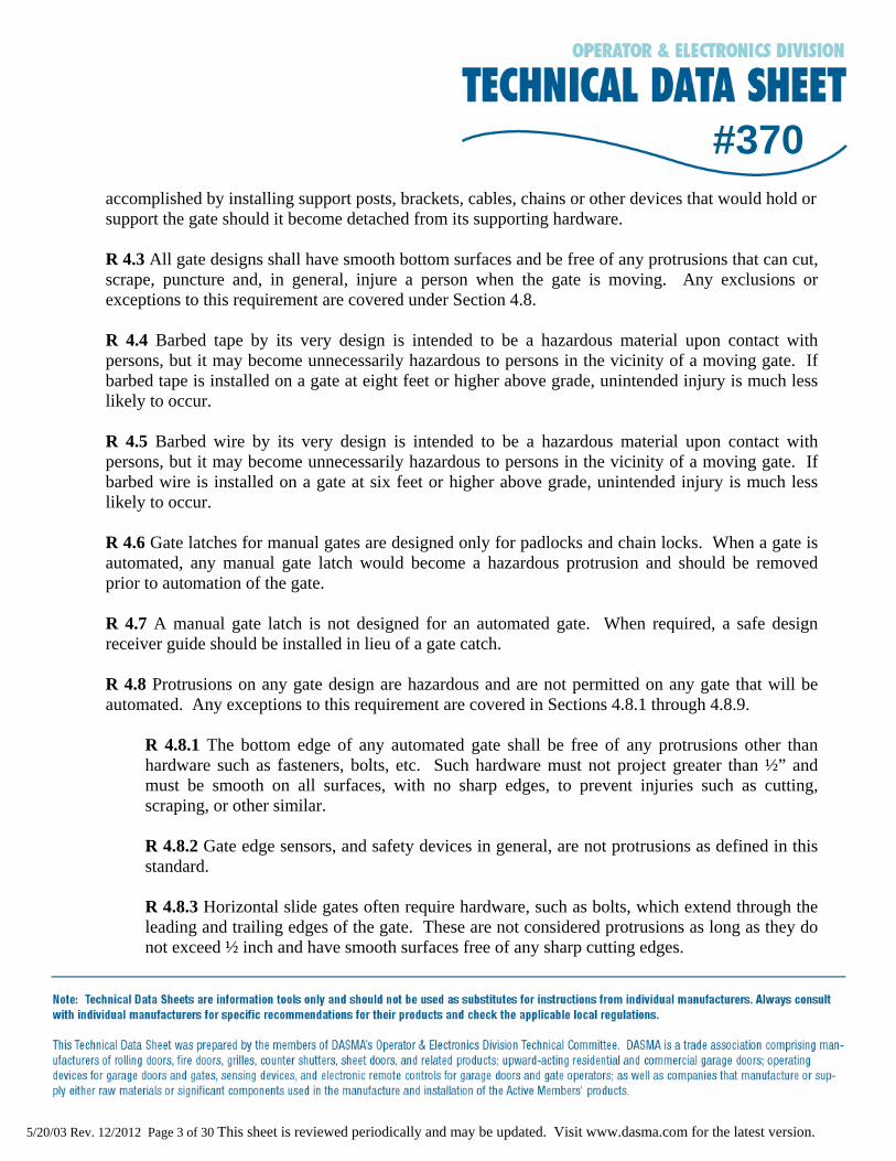
R 1. SCOPE
The standard has been developed to allow both performance-based and prescriptive-based methods. The standard provides gate designers/constructors/installers with pertinent requirements on how to build certain aspects of gates and pertinent requirements on meeting certain objectives in order to achieve safe operation of automated vehicular gates. Common gate types, which are based on descriptions found in UL 325, have been included. The scope mentions gate types not included in the standard to promote safe operation for such gates.
R 2. REFERENCED DOCUMENTS
ASTM F 2200 has been harmonized with ASTM gate construction standards for swing gates and slide gates. Automation of vehicular gates was outside the scope of those standards. The requirements for barbed tape are intended to be consistent with the ASTM practice for the installation of barbed tape. ASTM F 2200 has been harmonized with ANSI/UL 325, the standard governing gate operators. Various instructional requirements in ANSI/UL 325 have been incorporated into ASTM F 2200.
R 3. TERMINOLOGY
Many of the definitions have been extracted directly from ANSI/UL 325. Other gate related definitions are based on commonly accepted definitions within the gate industry. The definition for vehicular overhead pivot gates is based on a similar definition for vehicular overhead-type garage doors.
R 4. GENERAL REQUIREMENTS
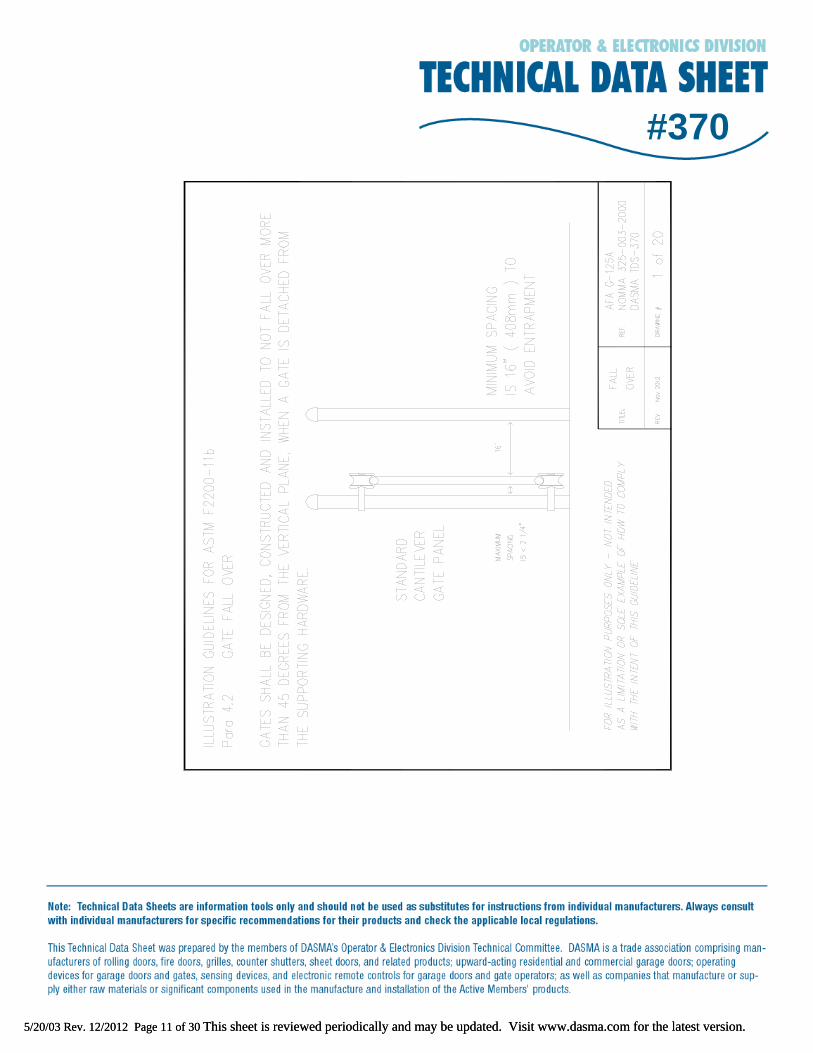
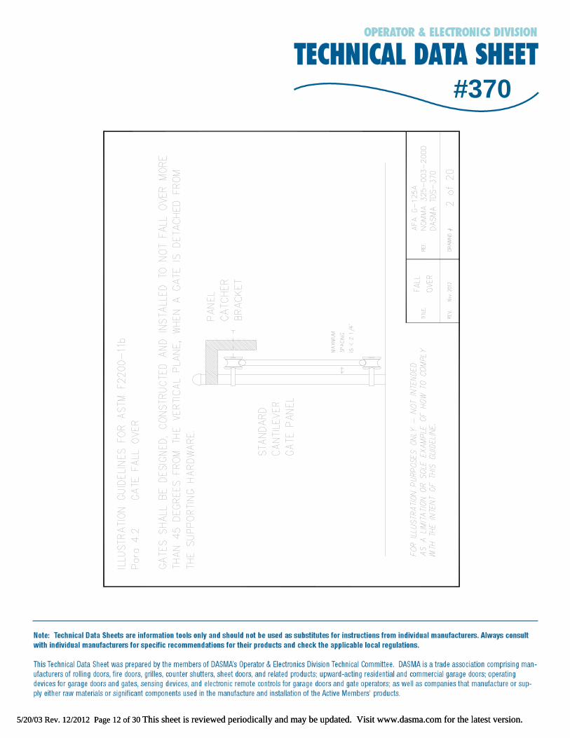
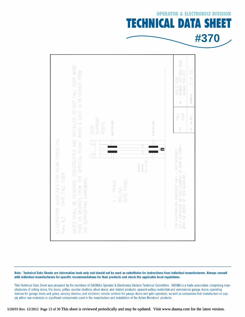
R 4.1 Gates have been divided into five basic designs of construction: horizontal slide, horizontal swing, vertical lift, vertical pivot and overhead pivot. These designs are considered to be the most common types being installed in the U.S. Each specific design shall be constructed and installed to conform to requirements that are unique to each particular gate type. R 4.2 All vehicular gate designs shall be constructed and installed with designs such that the gate cannot fall over more than 45 degrees from the vertical plane if detached from the gates supporting hardware, to prevent injury during service or in case of support failure. These designs can be accomplished by installing support posts, brackets, cables, chains or other devices that would hold or support the gate should it become detached from its supporting hardware.
5/20/03 Rev. 12/2012 Page 3 of 30 This sheet is reviewed periodically and may be updated. Visit www.dasma.com for the latest version.
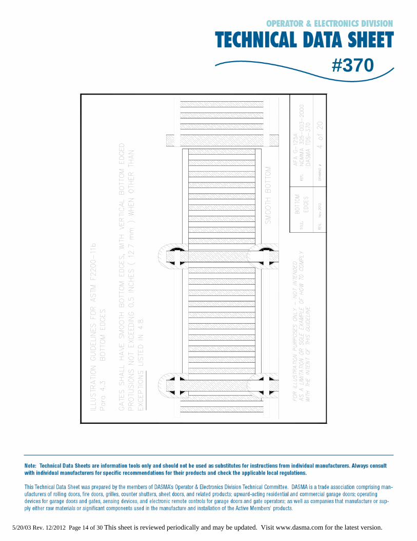
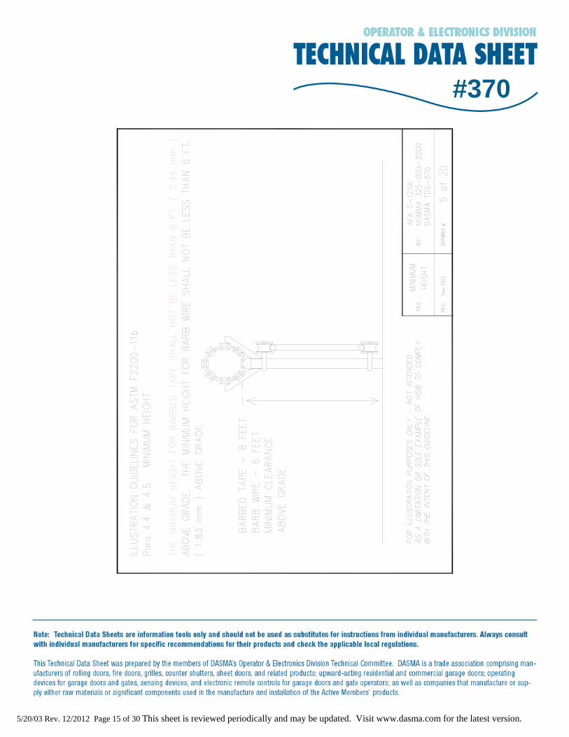
#370accomplished by installing support posts, brackets, cables, chains or other devices that would hold or support the gate should it become detached from its supporting hardware. R 4.3 All gate designs shall have smooth bottom surfaces and be free of any protrusions that can cut, scrape, puncture and, in general, injure a person when the gate is moving. Any exclusions or exceptions to this requirement are covered under Section 4.8. R 4.4 Barbed tape by its very design is intended to be a hazardous material upon contact with persons, but it may become unnecessarily hazardous to persons in the vicinity of a moving gate. If barbed tape is installed on a gate at eight feet or higher above grade, unintended injury is much less likely to occur. R 4.5 Barbed wire by its very design is intended to be a hazardous material upon contact with persons, but it may become unnecessarily hazardous to persons in the vicinity of a moving gate. If barbed wire is installed on a gate at six feet or higher above grade, unintended injury is much less likely to occur. R 4.6 Gate latches for manual gates are designed only for padlocks and chain locks. When a gate is automated, any manual gate latch would become a hazardous protrusion and should be removed prior to automation of the gate. R 4.7 A manual gate latch is not designed for an automated gate. When required, a safe design receiver guide should be installed in lieu of a gate catch. R 4.8 Protrusions on any gate design are hazardous and are not permitted on any gate that will be automated. Any exceptions to this requirement are covered in Sections 4.8.1 through 4.8.9.
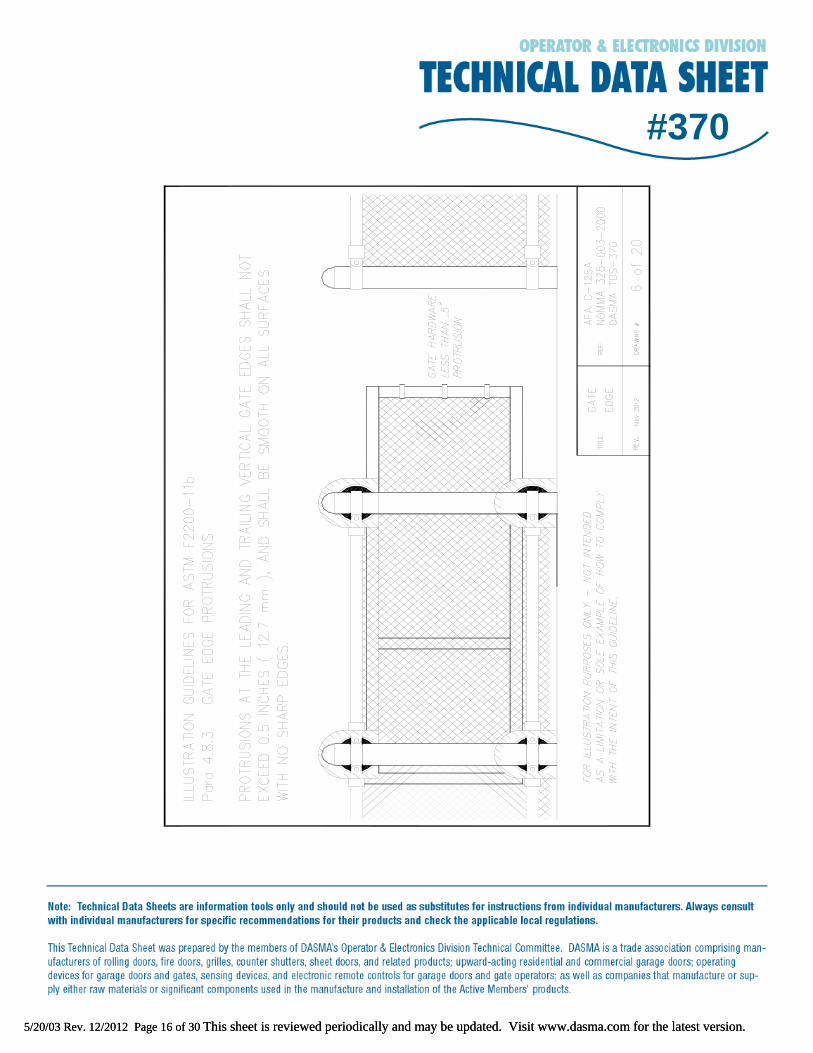
R 4.8.1 The bottom edge of any automated gate shall be free of any protrusions other than hardware such as fasteners, bolts, etc. Such hardware must not project greater than ½” and must be smooth on all surfaces, with no sharp edges, to prevent injuries such as cutting, scraping, or other similar. R 4.8.2 Gate edge sensors, and safety devices in general, are not protrusions as defined in this standard. R 4.8.3 Horizontal slide gates often require hardware, such as bolts, which extend through the leading and trailing edges of the gate. These are not considered protrusions as long as they do not exceed ½ inch and have smooth surfaces free of any sharp cutting edges.
5/20/03 Rev. 12/2012 Page 4 of 30 This sheet is reviewed periodically and may be updated. Visit www.dasma.com for the latest version.
#370R 4.8.4 Decorative designs such as pickets, scrolls, etc., shall not be considered protrusions on any gate type provided such designs do not extend outside the vertical plane. R 4.8.5 Gate locks are not considered protrusions, as long as the gate lock cross sectional area that could contact an individual is less than 9 square inches. Guide wheels for horizontal slide roll gates are not considered protrusions. The guide wheels are considered required hardware. However, all V-grooved rollers must be guarded. Positive stops that are required on all horizontal slide gates are not considered protrusions; however, positive stops should be installed at the top of the gate when possible. R 4.8.6 It is common for Class IV gates, which are designed for prisons, jails and military installations, to have a bottom lip or guide that extends below the bottom horizontal edge and usually slides through or along a gate guide embedment. This lip or guide is not considered a protrusion. R 4.8.7 Since vertical lift gates and vertical pivot gates move upward in a vertical plane, gate locks, top pickets and decorative designs are not considered protrusions R 4.8.8 Positive stops located at the top of a vertical lift gate shall not be considered a protrusion. R 4.8.9 A gate lock normally installed or mounted on the bottom horizontal edge of a vertical pivot gate shall not be considered a protrusion.
R 4.9 Gates should be installed to minimize unintentional or expected natural movement that could cause injury or entrapment to an individual when the gate is disconnected from the operator. R 4.10 This section defines conditions for locating a pedestrian gate, in order to keep pedestrians away from a moving automated vehicular gate.
R 5. SPECIFIC APPLICATIONS
R 5.1 Since this standard is written with the assumption that ANSI/UL 325 compliant gate operators will be installed on vehicular gates, existing gates that are to be automated may need to be upgraded.
R 5.2 Many of the risks posed by operation of an automated gate do not exist when someone moves a non-automated gate; therefore, standards for non-automated gates that will not be automated are
5/20/03 Rev. 12/2012 Page 5 of 30 This sheet is reviewed periodically and may be updated. Visit www.dasma.com for the latest version.
#370best handled by a separate standard. Pedestrian gates have means-of-egress related requirements that vehicular gates do not have, and are therefore best handled by a separate standard.
R 5.3 Since the assumption should be made that an existing gate operator will be replaced with an operator that is compliant with ANSI/UL 325, existing gates should be upgraded as needed.
R 6. VEHICULAR HORIZONTAL SLIDE GATES
R 6.1 Classes I, II and III could be combined because of the common aspect of prioritizing safety over security based on their respective applications.
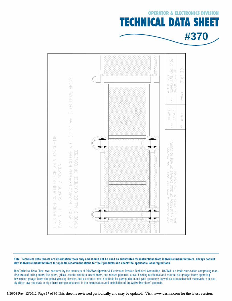
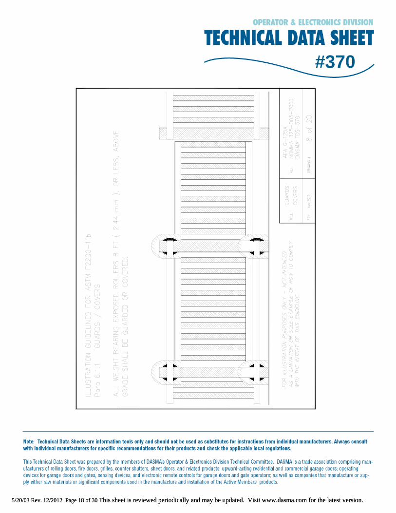
R 6.1.1 The eight foot parameter was chosen because any roller above this level could not present a hazard to a person using the gate, but rollers below this level need to be guarded so that persons could not come into direct contact with exposed rollers or bearings. The words “weight bearing” are used so as to provide some separation between rollers that can cause a “crushing” action against those rollers that can cause only a “pinch” action.
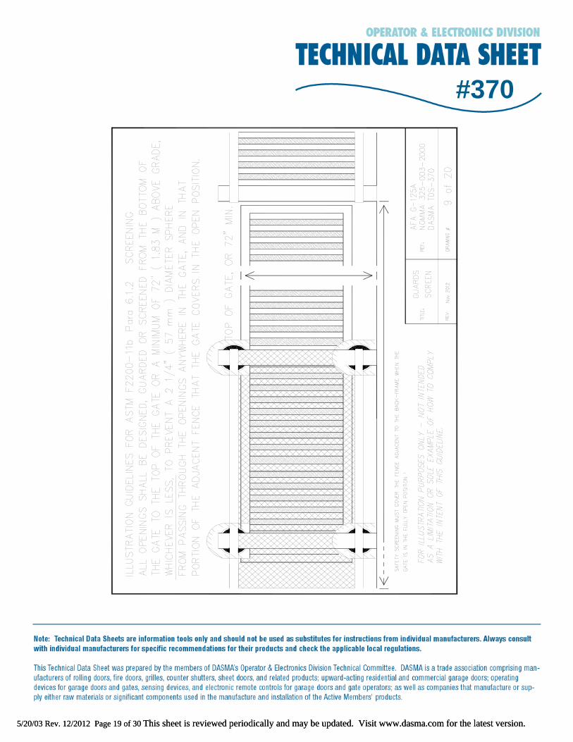
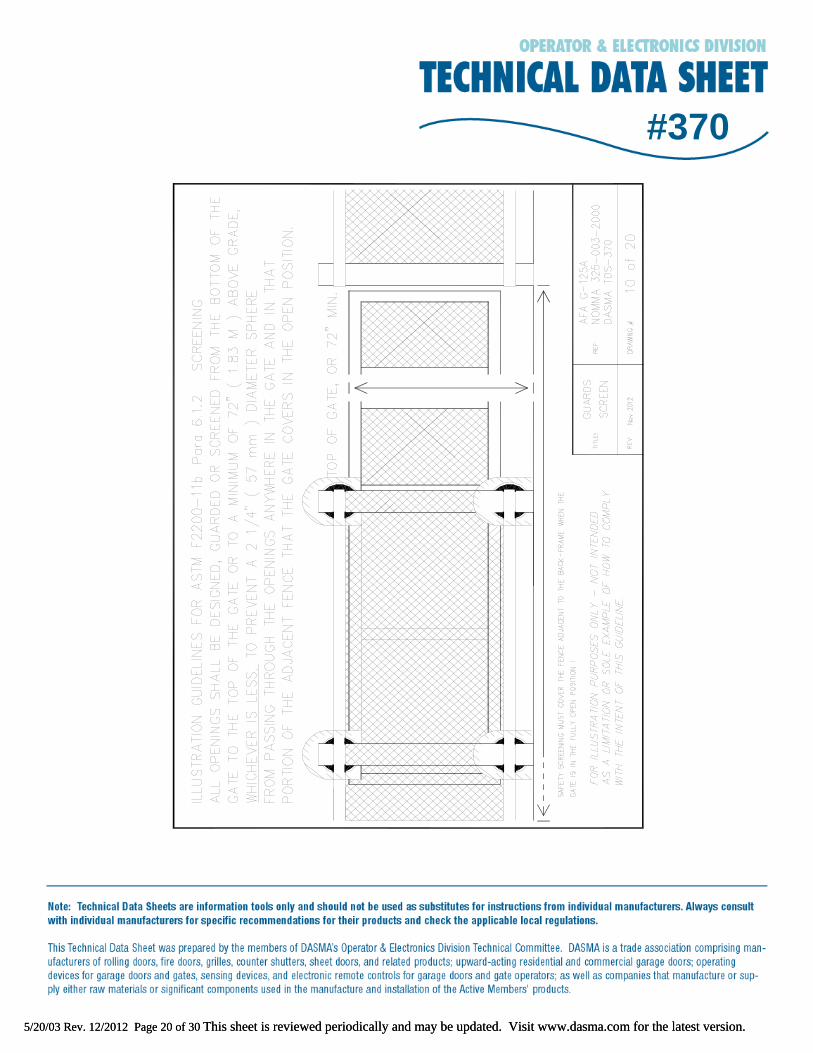
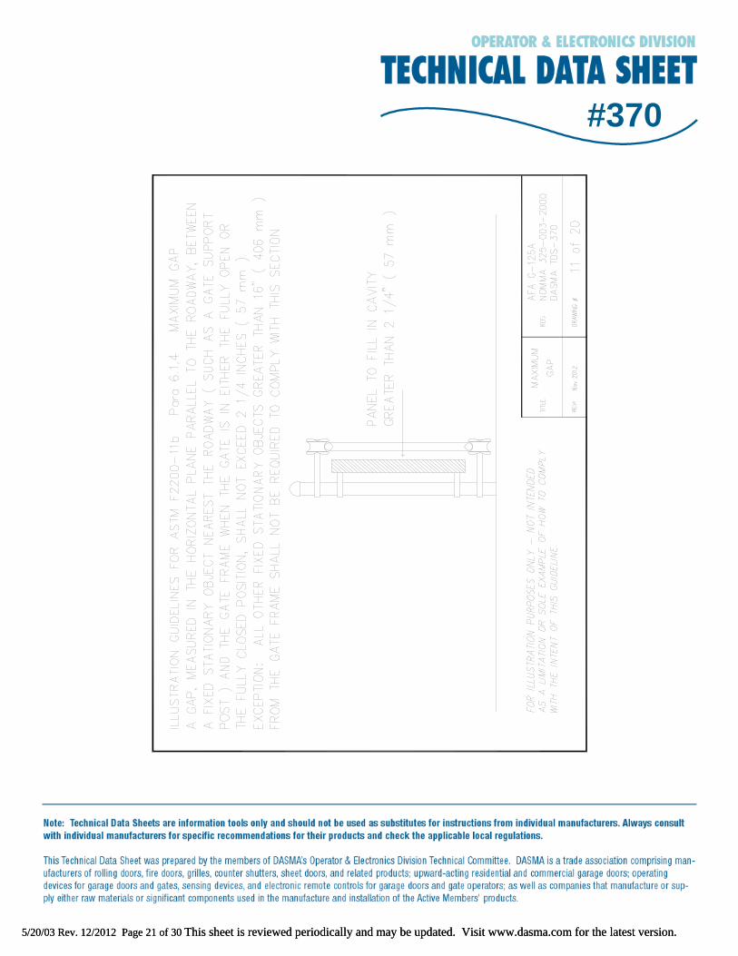
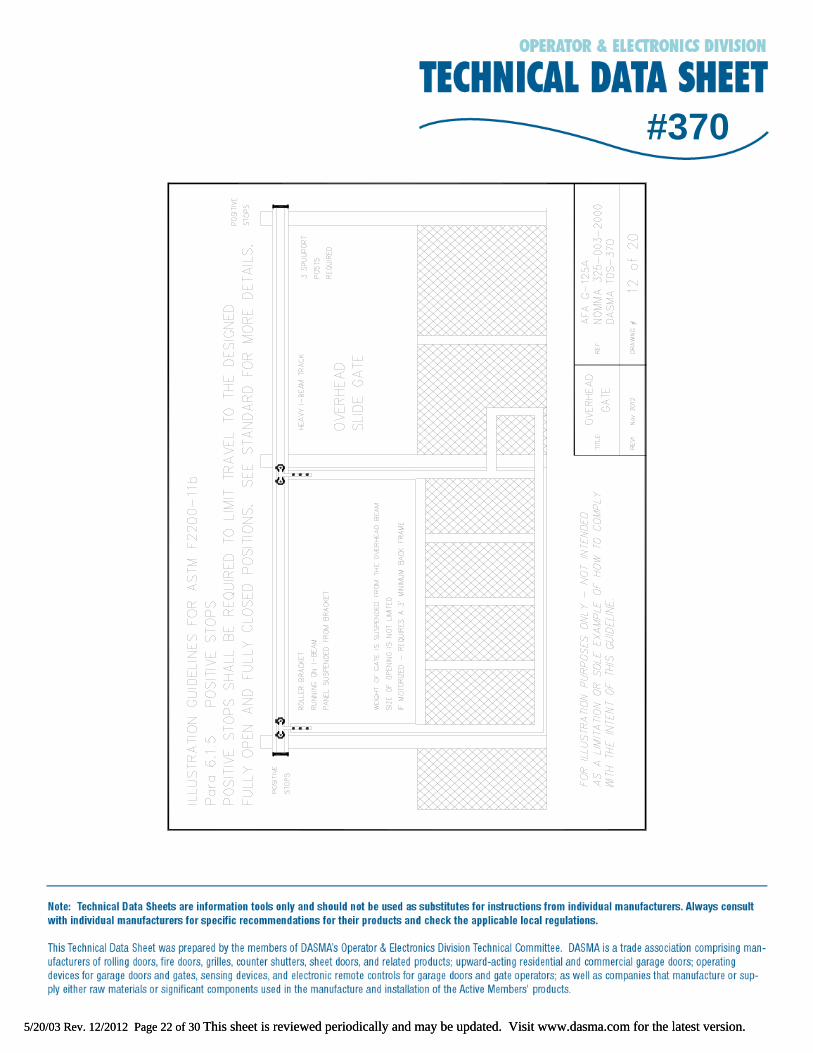
R 6.1.2 This section was written to be in harmony with the ANSI/UL 325 standard. In ASTM F2200-11b, the height was changed from 48" to 72" to better take into consideration the reach of individuals, and the alternate top-of-gate language was included to take into consideration the fact that gates may be less than 72" and must be screened to full height. R 6.1.3 This section was written to provide a standard for gate openings not addressed in the ANSI/UL 325 standard. The 2 1/4 inch dimension was chosen to be in harmony with Section 6.1.2. R 6.1.4 Information taken between 1985 and 2001 from the National Electronic Information Surveillance System published by the CPSC indicates that persons riding a horizontal slide gate while the gate was opening have had their head or body pulled into a gap between the moving gate panel and the support structure and subsequently suffered serious head or chest injuries or death by asphyxiation. The standard is intended to limit the gap in order to prevent or reduce the probability of the described occurrences from happening. The quantified limitation of the gap is consistent with the quantified limitation of guarding or screening of openings noted elsewhere in the standard. R 6.1.5 A potential hazard can be created when a slide gate is opened or closed beyond its supporting hardware. If this were to occur, the gate could fall and possibly cause injury to
5/20/03 Rev. 12/2012 Page 6 of 30 This sheet is reviewed periodically and may be updated. Visit www.dasma.com for the latest version.
#370persons in the area of the gate. Positive stops limit the lateral movement of the gate and prevent the gate from traveling beyond its design limit. The stops are to be installed at either the top or bottom of the gate because these areas would allow the stops to perform their intended function while minimizing any risk of pinching or crushing. R 6.1.6 Wind on a slide gate in operation can cause the gate to bend laterally beyond plumb during its travel from open to close. The lateral distance beyond plumb is a function of the gate surface area, gate length, gate construction, wind speed and wind direction, all of which are unpredictable and cannot be written into a standard.
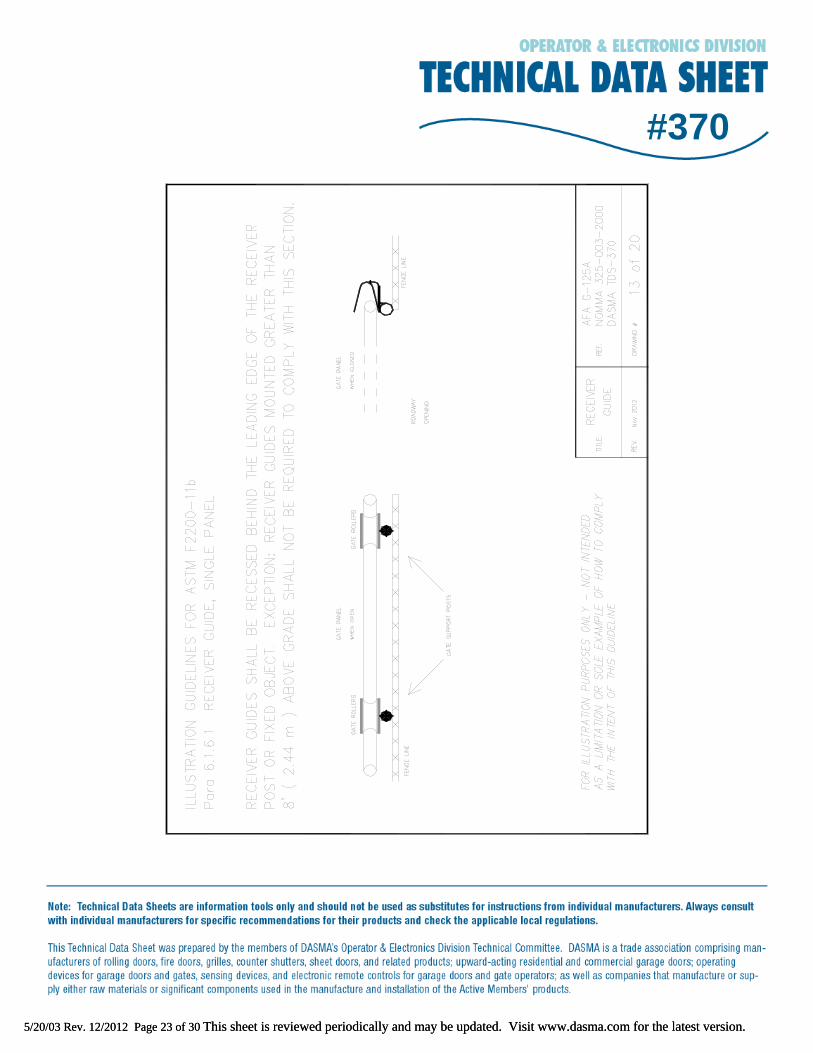
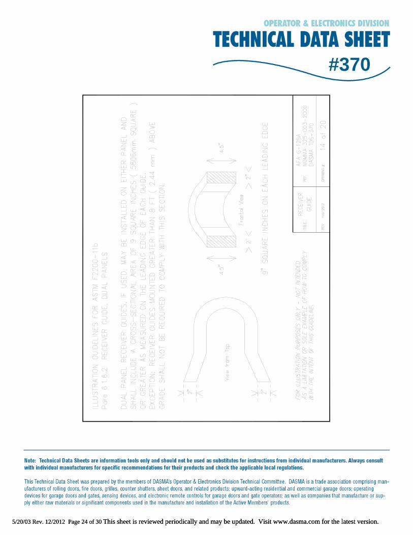
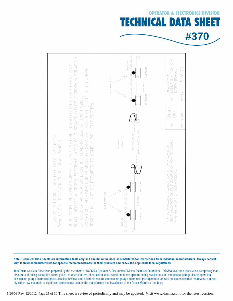
R 6.1.6.1 A receiver guide mounted behind the leading edge of the receiver post in single gate applications eliminates the receiver guide protruding into the opening and thus eliminates the guide as a possible puncture hazard. A receiver guide mounted greater than 8 feet above grade is not considered a puncture hazard to people in the vicinity of the gate. R 6.1.6.2 A receiver guide with greater than a 9 square inch cross-sectional area is not considered a puncture hazard to people in the vicinity of the gate.
R 6.2 Certain provisions that apply to Classes I, II and III gates are not applicable to Class IV gates because of the possibility of prioritizing security over safety in these applications.
R 7. VEHICULAR HORIZONTAL SWING GATES
R 7.1 Classes I, II and III could be combined because of the common aspect of prioritizing safety over security based on their respective applications.
R 7.1.1 A crushing or entrapment condition can be created with a fixed object and a gate moving in the direction of the fixed object. Exceptions are incorporated because ANSI/UL 325 allows for the installation of approved electronic devices to detect entrapment, or the potential thereof, as an alternative to the physical requirements.
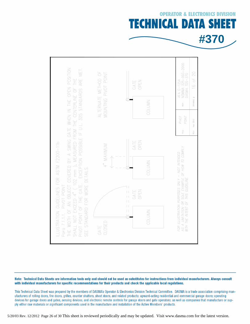
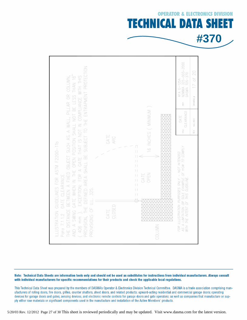
R 7.1.1.1 This provision allows for the required hardware, such as hinges or rods, to be installed but restricts the physical area to prevent crushing or entrapment of an individual. R 7.1.1.2 The established minimum distance requirement is to prevent entrapment between a fixed object such as a wall, fence, house, etc., and a gate in the open position.
5/20/03 Rev. 12/2012 Page 7 of 30 This sheet is reviewed periodically and may be updated. Visit www.dasma.com for the latest version.
#370R 7.2 No restrictions on this class of gate because of the security related applications under Class IV.
R 8. VEHICULAR VERTICAL LIFT GATES
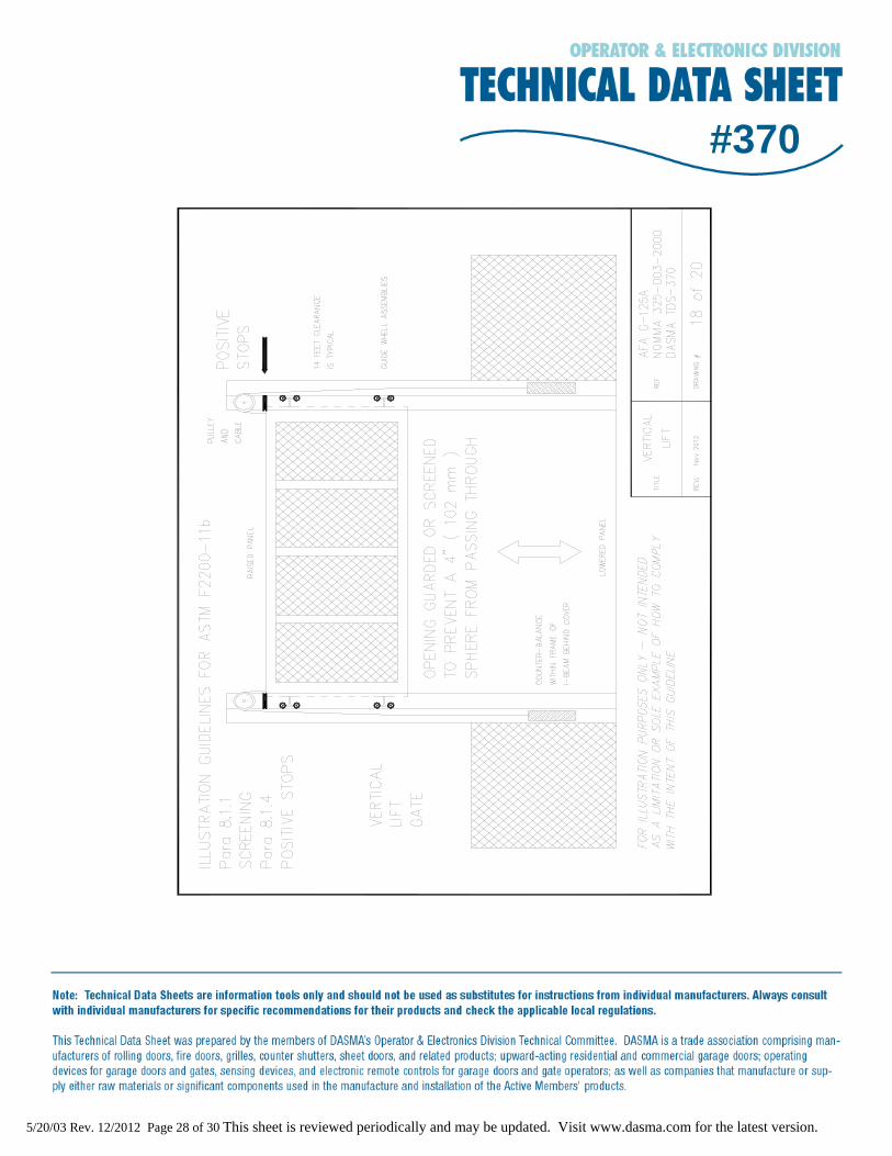
R 8.1 The safety / protective issues addressed in Sections 8.1.1 through 8.1.4 apply to Classes I, II and III vehicular vertical lift gates as these Classes of gates are most likely to be encountered by the general public.
R 8.1.1 Guarding / screening of the portion of the gate and/or fence that is covered by movement of the gate during travel is desired to reduce the opportunity for injuries caused by an individual “reaching through” those areas. R 8.1.2 Limiting the opening between a fixed, stationary object and any framing component of a moving gate is desired to reduce the likelihood that an individual can become entrapped between these surface areas. R 8.1.3 Although a gate operating vertically may not pull a person into a gap between a moving gate panel and a supporting structure in a manner similar to that described in horizontal slide gate related incidents, such a gate should be designed to prevent an individual from having their head or body enter such a gap. Therefore, the quantified limitation is consistent with the quantified limitation used in conjunction with current standard spacing for railings contained in building codes. R 8.1.4 A vertical lift gate shall have a means of preventing “over-travel” when moving toward the fully open position, thus avoiding the gate falling out of the guides.
R 8.2 Since Class IV gates are usually designed for prisons, jails and military installations, there may be specific security conditions at these sites that are prioritized over safety / protective issues.
R 9. VEHICULAR VERTICAL PIVOT GATES
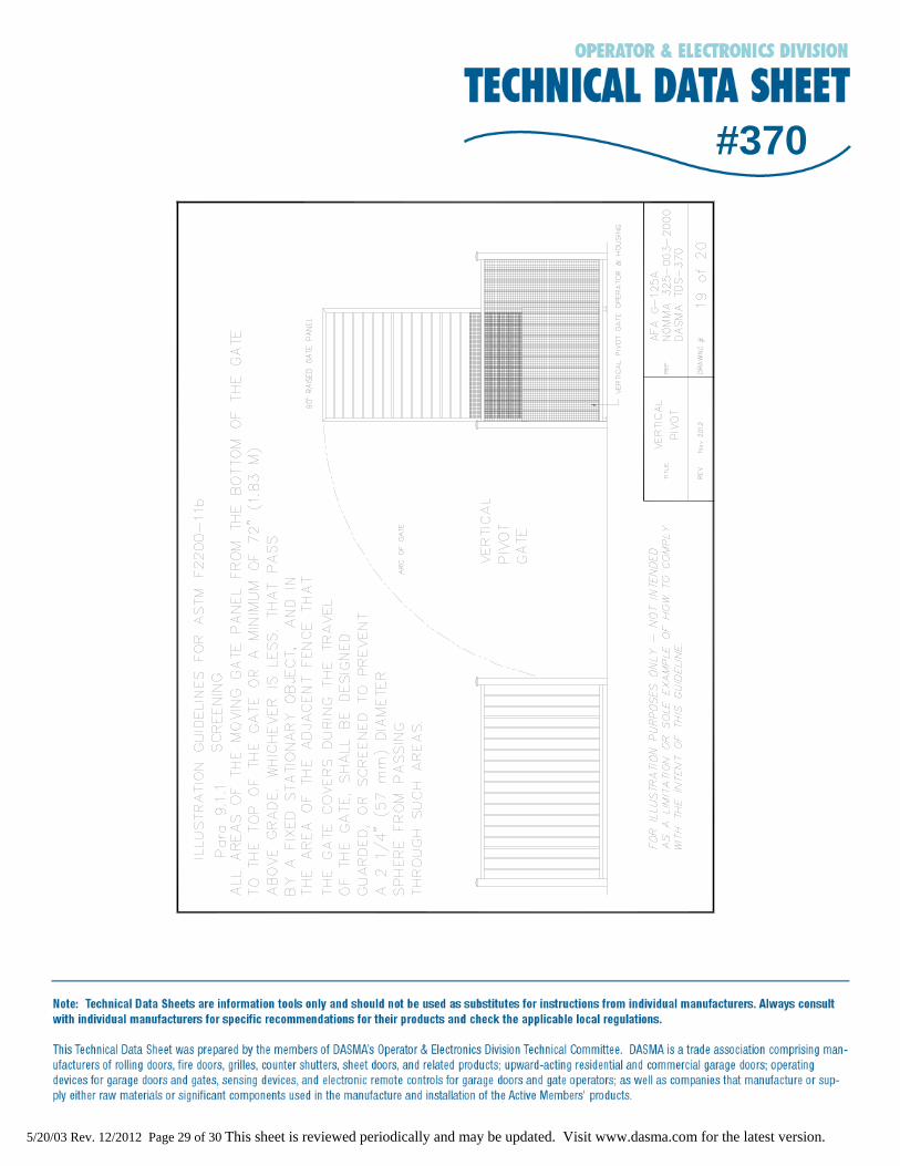
R 9.1 The safety / protective issues addressed in Sections 9.1.1 through 9.1.4 apply to Classes I, II and III vehicular vertical pivot gates as these Classes of gates are most likely to be encountered by the general public.
R 9.1.1 Guarding / screening of the portion of the gate and/or fence that is covered by movement of the gate during travel is desired to reduce the opportunity for injuries caused by an individual “reaching through” those areas. In ASTM F2200-11b, the language was revised
5/20/03 Rev. 12/2012 Page 8 of 30 This sheet is reviewed periodically and may be updated. Visit www.dasma.com for the latest version.
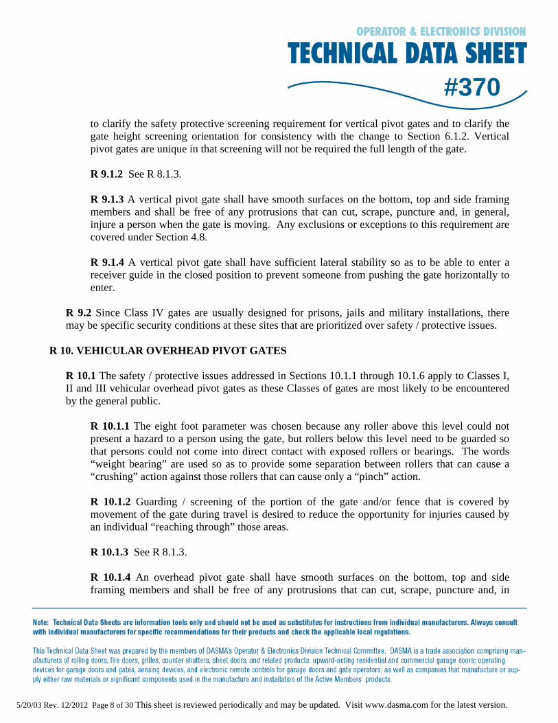
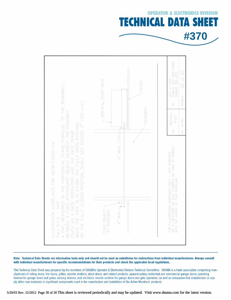
#370to clarify the safety protective screening requirement for vertical pivot gates and to clarify the gate height screening orientation for consistency with the change to Section 6.1.2. Vertical pivot gates are unique in that screening will not be required the full length of the gate. R 9.1.2 See R 8.1.3. R 9.1.3 A vertical pivot gate shall have smooth surfaces on the bottom, top and side framing members and shall be free of any protrusions that can cut, scrape, puncture and, in general, injure a person when the gate is moving. Any exclusions or exceptions to this requirement are covered under Section 4.8. R 9.1.4 A vertical pivot gate shall have sufficient lateral stability so as to be able to enter a receiver guide in the closed position to prevent someone from pushing the gate horizontally to enter.
R 9.2 Since Class IV gates are usually designed for prisons, jails and military installations, there may be specific security conditions at these sites that are prioritized over safety / protective issues.
R 10. VEHICULAR OVERHEAD PIVOT GATES
R 10.1 The safety / protective issues addressed in Sections 10.1.1 through 10.1.6 apply to Classes I, II and III vehicular overhead pivot gates as these Classes of gates are most likely to be encountered by the general public.
R 10.1.1 The eight foot parameter was chosen because any roller above this level could not present a hazard to a person using the gate, but rollers below this level need to be guarded so that persons could not come into direct contact with exposed rollers or bearings. The words “weight bearing” are used so as to provide some separation between rollers that can cause a “crushing” action against those rollers that can cause only a “pinch” action.
R 10.1.2 Guarding / screening of the portion of the gate and/or fence that is covered by movement of the gate during travel is desired to reduce the opportunity for injuries caused by an individual “reaching through” those areas. R 10.1.3 See R 8.1.3. R 10.1.4 An overhead pivot gate shall have smooth surfaces on the bottom, top and side framing members and shall be free of any protrusions that can cut, scrape, puncture and, in
5/20/03 Rev. 12/2012 Page 9 of 30 This sheet is reviewed periodically and may be updated. Visit www.dasma.com for the latest version.
#370general, injure a person when the gate is moving. Any exclusions or exceptions to this requirement are covered under Section 4.8.
R 10.1.5 A potential hazard can be created when an overhead pivot gate is opened beyond its supporting hardware. If this were to occur, the gate could fall and possibly cause injury to persons in the area of the gate. A positive stop can limit the lateral movement of the gate and prevent the gate from traveling beyond its design limit. The stop is to be installed at the top of the gate because this would allow the stop to perform its intended function while minimizing any risk of pinching or crushing.
R 10.1.6 The weight of an overhead pivot gate may cause serious injury to an individual if the gate should come loose and fall due to improper gate supporting mechanisms.
R 10.2 Since Class IV gates are usually designed for prisons, jails and military installations, there may be specific security conditions at these sites that are prioritized over safety / protective issues.
5/20/03 Rev. 12/2012 Page 10 of 30 This sheet is reviewed periodically and may be updated. Visit www.dasma.com for the latest version.
#370Illustration Guidelines
Dwg # Gate Type Description ASTM F 2200 Section
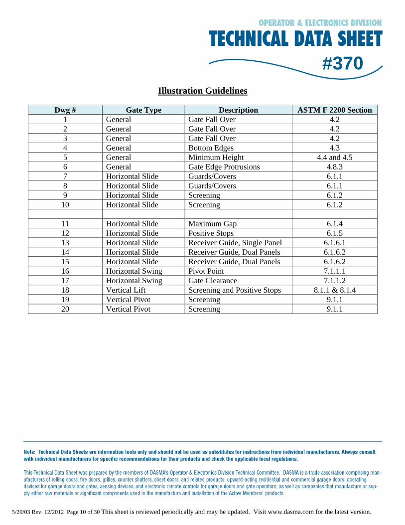
1 General Gate Fall Over 4.2 2 General Gate Fall Over 4.2 3 General Gate Fall Over 4.2 4 General Bottom Edges 4.3 5 General Minimum Height 4.4 and 4.5 6 General Gate Edge Protrusions 4.8.3 7 Horizontal Slide Guards/Covers 6.1.1 8 Horizontal Slide Guards/Covers 6.1.1 9 Horizontal Slide Screening 6.1.2 10 Horizontal Slide Screening 6.1.2
11 Horizontal Slide Maximum Gap 6.1.4 12 Horizontal Slide Positive Stops 6.1.5 13 Horizontal Slide Receiver Guide, Single Panel 6.1.6.1 14 Horizontal Slide Receiver Guide, Dual Panels 6.1.6.2 15 Horizontal Slide Receiver Guide, Dual Panels 6.1.6.2 16 Horizontal Swing Pivot Point 7.1.1.1 17 Horizontal Swing Gate Clearance 7.1.1.2 18 Vertical Lift Screening and Positive Stops 8.1.1 & 8.1.4 19 Vertical Pivot Screening 9.1.1 20 Vertical Pivot Screening 9.1.1
#370
#370
5/20/03 Rev. 12/2012 Page 11 of 30 This sheet is reviewed periodically and may be updated. Visit www.dasma.com for the latest version.
5/20/03 Rev. 12/2012 Page 11 of 30 This sheet is reviewed periodically and may be updated. Visit www.dasma.com for the latest version.
#370
#370
5/20/03 Rev. 12/2012 Page 12 of 30 This sheet is reviewed periodically and may be updated. Visit www.dasma.com for the latest version.
5/20/03 Rev. 12/2012 Page 12 of 30 This sheet is reviewed periodically and may be updated. Visit www.dasma.com for the latest version.
#370
#370
5/20/03 Rev. 12/2012 Page 13 of 30 This sheet is reviewed periodically and may be updated. Visit www.dasma.com for the latest version.
5/20/03 Rev. 12/2012 Page 13 of 30 This sheet is reviewed periodically and may be updated. Visit www.dasma.com for the latest version.
#370
5/20/03 Rev. 12/2012 Page 14 of 30 This sheet is reviewed periodically and may be updated. Visit www.dasma.com for the latest version.
#370
5/20/03 Rev. 12/2012 Page 15 of 30 This sheet is reviewed periodically and may be updated. Visit www.dasma.com for the latest version.
#370
#370
5/20/03 Rev. 12/2012 Page 16 of 30 This sheet is reviewed periodically and may be updated. Visit www.dasma.com for the latest version.
5/20/03 Rev. 12/2012 Page 16 of 30 This sheet is reviewed periodically and may be updated. Visit www.dasma.com for the latest version.
#370
#370
5/20/03 Rev. 12/2012 Page 17 of 30 This sheet is reviewed periodically and may be updated. Visit www.dasma.com for the latest version.
5/20/03 Rev. 12/2012 Page 17 of 30 This sheet is reviewed periodically and may be updated. Visit www.dasma.com for the latest version.
#370
#370
5/20/03 Rev. 12/2012 Page 18 of 30 This sheet is reviewed periodically and may be updated. Visit www.dasma.com for the latest version.
5/20/03 Rev. 12/2012 Page 18 of 30 This sheet is reviewed periodically and may be updated. Visit www.dasma.com for the latest version.
#370
#370
5/20/03 Rev. 12/2012 Page 19 of 30 This sheet is reviewed periodically and may be updated. Visit www.dasma.com for the latest version.
5/20/03 Rev. 12/2012 Page 19 of 30 This sheet is reviewed periodically and may be updated. Visit www.dasma.com for the latest version.
#370
#370
5/20/03 Rev. 12/2012 Page 20 of 30 This sheet is reviewed periodically and may be updated. Visit www.dasma.com for the latest version.
5/20/03 Rev. 12/2012 Page 20 of 30 This sheet is reviewed periodically and may be updated. Visit www.dasma.com for the latest version.
#370
#370
5/20/03 Rev. 12/2012 Page 21 of 30 This sheet is reviewed periodically and may be updated. Visit www.dasma.com for the latest version.
5/20/03 Rev. 12/2012 Page 21 of 30 This sheet is reviewed periodically and may be updated. Visit www.dasma.com for the latest version.
#370
#370
5/20/03 Rev. 12/2012 Page 22 of 30 This sheet is reviewed periodically and may be updated. Visit www.dasma.com for the latest version.
5/20/03 Rev. 12/2012 Page 22 of 30 This sheet is reviewed periodically and may be updated. Visit www.dasma.com for the latest version.
#370
#370
5/20/03 Rev. 12/2012 Page 23 of 30 This sheet is reviewed periodically and may be updated. Visit www.dasma.com for the latest version.
5/20/03 Rev. 12/2012 Page 23 of 30 This sheet is reviewed periodically and may be updated. Visit www.dasma.com for the latest version.
#370
#370
5/20/03 Rev. 12/2012 Page 24 of 30 This sheet is reviewed periodically and may be updated. Visit www.dasma.com for the latest version.
5/20/03 Rev. 12/2012 Page 24 of 30 This sheet is reviewed periodically and may be updated. Visit www.dasma.com for the latest version.
#370
5/20/03 Rev. 12/2012 Page 25 of 30 This sheet is reviewed periodically and may be updated. Visit www.dasma.com for the latest version.
#370
5/20/03 Rev. 12/2012 Page 26 of 30 This sheet is reviewed periodically and may be updated. Visit www.dasma.com for the latest version.
#370
5/20/03 Rev. 12/2012 Page 27 of 30 This sheet is reviewed periodically and may be updated. Visit www.dasma.com for the latest version.
#370
5/20/03 Rev. 12/2012 Page 28 of 30 This sheet is reviewed periodically and may be updated. Visit www.dasma.com for the latest version.
#370
5/20/03 Rev. 12/2012 Page 29 of 30 This sheet is reviewed periodically and may be updated. Visit www.dasma.com for the latest version.
#370
#370
5/20/03 Rev. 12/2012 Page 30 of 30 This sheet is reviewed periodically and may be updated. Visit www.dasma.com for the latest version.
5/20/03 Rev. 12/2012 Page 30 of 30 This sheet is reviewed periodically and may be updated. Visit www.dasma.com for the latest version.