Embed Size (px)
Citation preview
FAHTS User’s Manual. Examples 1
4 EXAMPLES
1. INTRODUCTION 2
1.1 General information 2 1.2 Basic commands 6
2. EXAMPLES OF USE 9
2.1 Single beam exposed to fire and protected on four sides. 9 2.2 Single beam exposed to fire on three sides. 13 2.3 Single beam exposed to fire on one side. 15 2.4 Single beam exposed to fire and protected on three sides. 16 2.5 Single beam exposed to fire on three sides. 17 2.6 Beam with displacement limitation and temp. dependant material properties. 19 2.7 Cantilever beam fully exposed to fire. 21 2.8 Cantilever beam exposed to two radiation sources. 25 2.9 Simple portal frame. 27 2.10 Simple portal frame. 30 2.11 3 Bay and 3 Storey frame. 33 2.12 9 Bay and 3 Storey frame. 37 2.13 Arched framework exposed to radiation and heat increment. 41 2.14 Single frame exposed to pool fire placed between columns. 44 2.15 Single frame exposed to pool fire placed between columns. 48
Summary of the examples
Mat. Prof. Exposure Protection Options1 Options2 Ex. 1: Alum Box Fully exp. Fully prot. Fire exp. a) Protection Ex. 2: Alum Box Partly exp. Fully prot. Fire exp. b) Protection Ex. 3: Alum Box Partly exp. Fully prot. Fire exp. c) Protection Ex. 4: Alum Box Partly exp. Partly prot. Fire exp. d) Protection Ex. 5: Alum I-prof Partly exp. Partly prot. Fire exp. e) Protection Ex. 6: Alum I-prof Partly exp. Partly prot. Displ. lim. Temp. dep Ex. 7: Steel Pipe Partly exp. Unprotected User source Radiation Ex. 8: Steel Pipe Partly exp. Unprotected User source Radiation Ex. 9: Steel I-prof Fully exp. Unprotected User source Temp. hist. Ex. 10: Steel I-prof Fully exp. Unprotected User source Temp. hist. Ex. 11: Steel I-prof Partly exp. Unprotected User source Temp. hist. Ex. 12: Steel I-prof Partly exp. Unprotected User source Temp. hist. Ex. 13: Steel I-prof Partly exp. Unprotected Radiation Temp. hist. Ex. 14: Steel Pipe Fully exp. Unprotected Kameleon Static ana. Ex. 15: Steel Pipe Fully exp. Unprotected Kameleon Temp. sim.
_________________________________________________________________ 2005-01-01
1

FAHTS User’s Manual Examples 2
1. Introduction
1.1 General information This manual contains some examples that describe the method for fire analysis by use of FAHTS and USFOS. FAHTS and USFOS are interlinked. Both are needed for a fire analysis of a structure. The output from FAHTS is input for USFOS. The FAHTS input can be given in one or two files. In this manual all input are separated in a Control file and a Structure file. ( See Figure 1.1-1 for a Structure file.) The input contains information about the heat source, thermal parameters for the structure and insulation, the structure with node numbers, co-ordinates, elements, cross-section geometry and mechanical loads. It is not necessary to give commands with default values if the default value is suitable. The output includes an out file Figure 1.1-2(short version), which contains a summary of the input and the temperature analysis done by FAHTS. The results include Time, Accumulated energy, Max heat input and Max/Min temperature after each load step. Another output is the Beltemp file, Figure 1.1-3, which includes the temperature increment of the elements for each load step of the fire load. Some of the files shown in this introduction chapter are not included in the examples. This is because they take up too much space, and because they have no importance to this manual. Filenames used in the examples: File type: File name: FAHTS Control file fahts.fem USFOS Control file usfos.fem FAHTS out file resf.out USFOS out file resu.out Structure file stru.fem
_________________________________________________________________ 2005-01-01
2

FAHTS User’s Manual Examples 3
HEAD Structure file Single beam '------------------------------------------------------------------------- ' ELEMENT AND NODE NUMBERS '------------------------------------------------------------------------- ' * Node co-ordinates. Boundary conditions * ' Node ID X Y Z Boundary code ' x y z rx ry rz NODE 1 0.000 0.000 0.0 1 1 1 1 0 0 NODE 2 2.200 0.000 0.0 NODE 3 4.400 0.000 0.0 0 1 1 1 0 0 ' ' ' * Element numbers and node numbers. Geometry ID * ' Elem_ID np1 np2 material geom lcoor ecc1 ecc2 BEAM 12 1 2 1 10 BEAM 23 2 3 1 10 '------------------------------------------------------------------------- ' CROSS-SECTION GEOMETRY '------------------------------------------------------------------------- ' Geom_ID H T-side T-bott T-top Width BOX 10 0.300 0.008 0.008 0.008 0.200 ' '------------------------------------------------------------------------- ' LOAD CASES '------------------------------------------------------------------------- ' Load_case Node_ID Fx Fy Fz NODELOAD 1 2 0 0 -1.0E4 ' ' ' Load_case AccX AccY AccZ GRAVITY 2 0 0 -9.81
Figure 1.1-1: Structure file for FAHTS and USFOS, stru.fem.
********************************** ******* F A H T S ******* ********************************** ====== A N A L Y S I S P A R A M E T E R S ====== F A H T S temperature simulations Single beam, box cross-section
Example No. 1 FAH St n 1 1 1 1 1 1 1 1Figure 1.1-
_________
Number of nodal points = 3 Number of elements = 2 +++++ TS ep Time Accum. Max heat Max Min o. energy input temp. temp. (s) (J) (W/m2) (degr C) (degr C) 1 36.00 6.338E+04 1.13E+03 16.0 14.9 2 72.00 2.972E+05 2.62E+03 19.4 15.3 3 108.00 7.562E+05 4.69E+03 26.2 16.5 4 144.00 1.455E+06 6.45E+03 36.4 19.1 5 180.00 2.371E+06 8.18E+03 49.9 23.3 6 216.00 3.405E+06 8.39E+03 65.0 29.2 7 252.00 4.441E+06 8.29E+03 80.0 36.5 8 288.00 5.478E+06 8.49E+03 94.8 44.9 9 324.00 6.515E+06 8.38E+03 109.4 53.9 0 360.00 7.548E+06 8.57E+03 123.8 63.2 1 396.00 8.579E+06 8.45E+03 138.0 72.7 2 432.00 9.609E+06 8.64E+03 151.9 82.5 3 468.00 1.064E+07 8.51E+03 165.6 92.8 4 504.00 1.165E+07 8.39E+03 178.9 103.3 5 540.00 1.266E+07 8.56E+03 191.9 113.7 6 576.00 1.366E+07 8.44E+03 204.8 124.0 7 612.00 1.464E+07 8.31E+03 217.3 134.4
2: Out file from FAHTS analysis, resf.out.
________________________________________________________ 2005-01-01
3

FAHTS User’s Manual Examples 4
' ***************************** ' ** Temperature increments ** ' ** calculated ** ' ** by ** ' ** F A H T S ** ' ***************************** ' load case time LCASETIM 4 360.0 ' ' load_case element Mean Gradient Gradient ' no number temperature Y-dir Z-dir ' (increment) (increment) (increment) BELTEMP 4 12 103.722 -.088 -171.821 BELTEMP 4 23 103.722 -.088 -171.818 ' ' load_case time LCASETIM 5 720.0 ' ' load_case element Mean Gradient Gradient ' no number temperature Y-dir Z-dir ' (increment) (increment) (increment) BELTEMP 5 12 117.532 -.274 -79.993 BELTEMP 5 23 117.532 -.274 -79.984 ' ' load_case time LCASETIM 6 1080.0 ' ' load_case element Mean Gradient Gradient ' no number temperature Y-dir Z-dir ' (increment) (increment) (increment) BELTEMP 6 12 100.828 -.516 -9.241 BELTEMP 6 23 100.827 -.516 -9.225
Figure 1.1-3: Beltemp file from FAHTS analysis, resf_beltemp.fem.
The Beltemp file from FAHTS is one of the input files for USFOS. Other input for USFOS is in this manual separated in two files, a Control file and a Structure file. Before running USFOS it can be smart checking out file and inspecting in XFOS. USFOS gives a Status file, an out file and a raf-file. The Status file (see Figure 1.1-4) contains a short summary of the results from USFOS. Among other things, time before yield and plastic hinge, and utilization of the beam. The USFOS .out file contains a summary of the input and a list of displacement and reaction forces for each load step. The raf-file contains all the information needed for a view in XFOS. This is not a legible file.
_________________________________________________________________ 2005-01-01
4

FAHTS User’s Manual Examples 5
--- U S F O S A N A L Y S I S S T A T U S --- U S F O S progressive collapse analysis Single beam, box cross-section Example No. 1 Input files: usfos.fem stru.fem res_beltemp.fem Number of nodal points : 3 Number of elements : 2 Time First yield at : 1146.413 First plastic hinge at : 1206.374 No buckling detected Exceeding utilization threshold of : 1.10 at : 1207.094 Max number of negative pivot element : 1 at : 1207.094 Analysis terminated at : 1207.094 -- Yielding Status -- Elem ID Position Cross sect. Time utilization 12 node 2 .83 1146.413 13 node 1 .83 1146.413 -- Plastic hinge Status -- Elem ID Position Cross sect. Time utilization 12 node 2 1.00 1206.374 23 node 1 1.00 1206.734 -- Elements Exceeding utilization of 1.10 -- Elem ID Position Cross sect. Time utilization 23 node 1 1.11 1207.094 ----- E N D A N A L Y S I S S T A T U S -----
Figure 1.1-4: Status-file from USFOS, resu_status.text.
It's importa t to write input files in an orderly way, to obtain a good readability. This makes it ea ier to find errors and correct them, and it's easier to see what the file contains. Space is usIt's thereforPlease notea new comm It is possiblone of the cprogram wiin the exam
_________
ns
ed as the only dividing sign. The number of spaces is of no importance. e possible to line up the numbers under each other. that the program reads character by character, and a command lasts until
and is given.
e to write explanations to the commands and make "headings" as long as omment characters are put in front. See USFOS User's Manual. The ll ignore the text behind these characters. The command characters used ples in this manual are mostly " ' " and " ! ".
________________________________________________________ 2005-01-01
5

FAHTS User’s Manual Examples 6
1.2 Basic commands This chapter contains information about some of the basic FAHTS commands. The commands are also explained in the FAHTS User's Manual. It is very important to write a command only once, if it's said so in the manual. If a command is given more than one time, and are changed a bit, this can lead to an analysis error. HEAD: This command is written in the FAHTS and USFOS input files. It makes room for three lines of text identifying the analysis. The three lines will be repeated in some of the output files.
HEAD U S F O S progressive collapse analysis Single b HUP
eam
Figure 1.2-1: HEAD command.
MOVIEPRI: By writing this command the storing of the temperature analysis model and the temperature result at the specified time increments are switched ON. This makes it possible to inspect the structure by XFOS before running USFOS. SHAPFACT: By writing this command shape factor calculations are switched ON. Radiation between temperature elements belonging to the same FEM structural element is included. (Radiation inside tubes). TEMPMESSpecifies thoverridden
' TEMPMESH
Figure 1.2-
MESHBOXSpecifies thManual for
'----------' '----------' MESHBOX
Figure 1.2-
_________
H: e temperature mesh refinement of the profile. Note that this command is by the MESH… commands. See FAHTS User's Manual for details.
n_length n_circ 2 16
2: TEMPMESH command.
: e temperature mesh refinement for box cross-sections. See FAHTS User's details. -------------------------------------------------------------- PROFILE MESH --------------------------------------------- n_length n_side n_top n_bott
-----------------
2 8 4 4
3: MESHBOX command.
________________________________________________________ 2005-01-01
6

FAHTS User’s Manual Examples 7
MESHIPRO: Specifies the temperature mesh refinement for I cross-sections. See FAHTS User's Manual for details.
'------------------------------------------------------------------------- ' PROFILE MESH '------------------------------------------------------------------------- ' n_length n_web n_top n_bott elem_id elem_id elem_id MESHIPRO 8 1 2 2 MESHIPRO 8 6 6 6 1112 111 212
Figure 1.2-4: MESHIPRO command.
MESHPIPE: Specifies the temperature mesh refinement for pipe cross-sections. See FAHTS User's Manual for details. There are six possible ways to define a thermal "load". These are: FIREINT: Specifies that the environmental temperature and radiation are read from the FIREINT result database. See examples with exposure set to FIREINT. HCFIRE: Specifies that the environmental temperature field follows the standard hydrocarbon fire temperature development defined by NPD. See examples with option Fire exposure a), b), c), d) and e). ISOFIRE: Specifies that the environmental temperature field follows the standard ISO temperature development, as specified in the ISO-834. USERFIRE: The user specifies a radiating source used for simplified fire scenarios, which may be constant (hist = 1), or vary as a function of time, according to the specified time history. See examples with the option Radiation. USERTEMP: The user specifies the environmental level, which may be constant (hist = 1), or vary as a function of time, according to the specified time history. See examples with the option Temp.history. USERJET: The user specifies a jet source used for simplified fire scenarios, which may be constant (hist = 1), or vary as a function of time, according to the specified time history. See FAHTS User's Manual. TEMPSIM: This command MUST be supplied. The command TEMPSIM contains information about the duration of the fire, the number of time steps to be used, and time between saving of results. The last number tells that a new load case is written to file every 900 sec (in Figure 1.2-5). The temperature results are saved to the Beltemp file, see Figure 1.1-3.
_________________________________________________________________ 2005-01-01
7

FAHTS User’s Manual Examples 8
F A H T S temperature simulation Beam + Column '------------------------------------------------------------------------- ' ANALYSIS TIME AND TEMPERATURE STEPS '---------------------------------------------------------' end-time (s) nstep resinc (s)
----------------
TEMPSIM 10800.0 300 900.0
Figure 1.2-5: TEMPSIM command.
THERMPAR: This command MUST be supplied. Specifies the thermal properties of the materials used in the structure. See figure below. INSIDPAR: Specifies the thermal properties of the material inside hollow members. See figure below. INSULPAR: Specifies the thermal properties of the insulation used to protect structural members. See figure below. ELMINSUL: Specifies the elements, which should have the actual insulation. See figure below.
'------------------------------------------------------------------------- ' THE MATERIAL'S AND INSULATION'S THERMAL PARAMETERS '--------------------------------------------------------------' * Thermal parameters of the material *
-----------
' id rho (kg/m3) c (J/kgK) k (W/mK) emiss THERMPAR 1 2700.0 896.0 200.0 0.20 ' ' * Thermal parameters of the inside material * ' id rho (kg/m3) c (J/kgK) INSIDPAR 1 1.273 0.7 ' ' * Thermal parameters of the insulation * ' insul-ID type K (W/m2K) emiss INSULPAR 1 1.0 10.0 0.8 ' ' * Elements with insulation * ' insul_ID Elem1 Elem2 .... ELMINSUL 1
Figure 1.2-6: Thermal parameters.
_________________________________________________________________ 2005-01-01
8

FAHTS User’s Manual Examples 9
2. Examples of use
2.1 Single beam exposed to fire and protected on four sides. Key words:
Ex. 1: Alum Box Fully exp. Fully prot. Fire exp. a) Protection
Material: Aluminium AA 6082-T6. Property reduction due to increased
temperature, according to Eurocode 1999 Part 1-2. Structure: Single beam, aluminium, mid span force, full exposure, full
protection. This example shows the definition of the exposure and the protection of a profile. The beam is modelled with two elements, as shown in Figure 2.1-1.
Figure 2.1-1: Structural model with node and element numbers.
Beam length : 4.400 m Profile width : 0.200 m (width) height : 0.300 m (height)
thickness : 0.008 m (thickness) Yield stress : σ = 255 MPa Aluminium AA 6082-T6 Youngs modulus : E = 70000 MPa Aluminium Mid span force : 100 kN Fire load : HC-fire Similar beams are used in the three following examples, but with different fire exposure and protection. The Control files are therefore only included in their totality in this example. In the following examples only the parts of the Control files that are changed are included.
_________________________________________________________________ 2005-01-01
9

FAHTS User’s Manual Examples 10
Problem: Beam with full exposure, and protection on all sides. Solution: No specification of exposure and protection, means that the entire cross-section is exposed to the heat source, and protected. This is to simplify the writing of the Control file.
HEAD F A H T S temperature simulations Single beam, box cross-section LIN_RULE 2 SHAPFACT ! Calculation of section factor is on. MOVIEPRI ! Results from FAHTS can be shown in XFOS. '------------------------------------------------------------------------- ' TYPE OF FIRE AND EXPOSURE '------------------------------------------------------------------------- HCFIRE ! Hydrocarbon fire. ' ' * Initial temperature in the fire compartment * ' initemp INITEMP 15.0 ' ' * Exposure time * ' end-time (s) nstep resinc (s) TEMPSIM 3600 100 360 '------------------------------------------------------------------------- ' THE MATERIAL'S AND INSULATION'S THERMAL PARAMETERS '------------------------------------------------------------------------- ' * Thermal parameters of the material * ' id rho (kg/m3) c (J/kgK) k (W/mK) emiss THERMPAR 1 2700.0 896.0 200.0 0.20 ' ' * Thermal parameters of the inside material * ' id rho (kg/m3) c (J/kgK) INSIDPAR 1 1.273 0.7 ' ' * Thermal parameters of the insulation * ' insul-ID type K (W/m2K) emiss INSULPAR 1 1.0 10.0 0.8 ' ' * Elements with insulation * ' insul_ID Elem1 Elem2 .... ELMINSUL 1 ! All elements have insulation. ' '------------------------------------------------------------------------ ' PROFILE MESH '------------------------------------------------------------------------ ' n_length n_side n_top n_bott MESHBOX 2 8 4 4
Figure 2.1-2: FAHTS Control file, fahts.fem.
_________________________________________________________________ 2005-01-01
10

FAHTS User’s Manual Examples 11
HEAD U S F O S progressive collapse analysis Single beam HUP ' DETEROFF CMAXSTEP 1200 ! Increasing from default 512 to 1200. ' XFOSFULL ! All data are saved for view in XFOS. ' '------------------------------------------------------------------------- ' LOAD HISTORY AND DEFORMATION CONTROL '------------------------------------------------------------------------- ' * Load history specification with load and deformation * ' nloads npostp mxpstp mxpdis CICYFOS 10 100 1 1 ' lcase lfact mxld mxdisp nstep minstp 2 1.0 1.0 0.0 10 0.001 ! Gravity. 1 1.0 2.0 -0.250 100 0.001 ! Node load. 4 0.02 1.0 -0.250 200 0.001 ! Fahts Fire Load 5 0.02 1.0 -0.250 200 0.001 ! Fahts Fire Load 6 0.02 1.0 -0.250 200 0.001 ! Fahts Fire Load 7 0.02 1.0 -0.250 200 0.001 ! Fahts Fire Load 8 0.02 1.0 -0.250 200 0.001 ! Fahts Fire Load ' ' * Specification for deformation control of the structure * ' ncnods CNODES 1 ' nodex idof dfact 2 3 1 '------------------------------------------------------------------------- ' MATERIAL PROPERTIES '------------------------------------------------------------------------- ' mat_no E-mod poiss yield density therm.exp MISOIEP 1 70000.0E6 0.3 255.0E6 2700.0 2.3E-5 ' '------------------------------------------------------------------------- ' REDUCTION CURVES OF MATERIAL PROPERTIES '------------------------------------------------------------------------- ' mat_no dep_E dep_Yield USERTDEP 1 1 2 ' ' curve_no Temp Red ! Reduction curve of E-modul TEMPDEPY 1 20 1.0 50 0.99 100 0.97 150 0.93 250 0.78 200 0.86 250 0.78 300 0.68 350 0.54 400 0.40 550 0.0 ' ' curve_no Temp Red ! Reduction curve of yield TEMPDEPY 2 20 1.0 100 1.0 150 0.79 200 0.65 250 0.38 300 0.20 350 0.11 550 0.0
Figure 2.1-3: USFOS Control file, usfos.fem.
_________________________________________________________________ 2005-01-01
11
FAHTS User’s Manual Examples 12
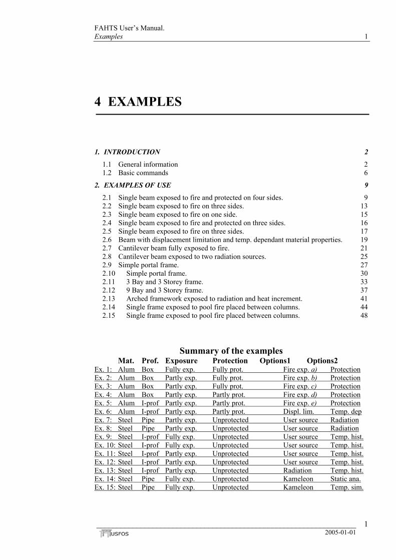
********************************** ******* F A H T S ******* ********************************** Version 3.1 / Release 98-03-09 S I N T E F - Analysis initiated at - 98-06-15 15:48:42 Licenced to : SINTEF ====== A N A L Y S I S P A R A M E T E R S ====== F A H T S temperature simulations Single beam, box cross-section Number of nodal points = 3 Number of elements = 2 Minimum Accepted Temperature : -273.00 Maximum Accepted Temperature : 3000.00 FAHTS Step Time Accum. Max heat Max Min no. energy input temp. temp. (s) (J) (W/m2) (degr C) (degr C) 1 36.00 8.250E+04 1.13E+03 16.0 16.0 2 72.00 3.780E+05 2.62E+03 19.5 19.4 3 108.00 9.549E+05 4.68E+03 26.2 26.2 4 144.00 1.832E+06 6.41E+03 36.5 36.5 5 180.00 2.980E+06 8.10E+03 50.0 50.0 6 216.00 4.273E+06 8.25E+03 65.2 65.1 7 252.00 5.566E+06 8.09E+03 80.4 80.3 8 288.00 6.855E+06 8.22E+03 95.5 95.4 9 324.00 8.142E+06 8.05E+03 110.7 110.5 10 360.00 9.425E+06 8.18E+03 125.7 125.6 - 90 3240.00 5.164E+07 9.15E+02 623.8 618.0 91 3276.00 5.168E+07 9.00E+02 624.3 618.5 92 3312.00 5.173E+07 8.85E+02 624.8 619.0 93 3348.00 5.177E+07 8.71E+02 625.3 619.5 94 3384.00 5.181E+07 8.58E+02 625.8 619.9 95 3420.00 5.184E+07 8.46E+02 626.2 620.4 96 3456.00 5.188E+07 8.35E+02 626.6 620.8 97 3492.00 5.191E+07 8.24E+02 627.0 621.1 98 3528.00 5.194E+07 8.13E+02 627.3 621.5 99 3564.00 5.197E+07 8.04E+02 627.7 621.8 10 3600.00 5.199E+07 7.94E+02 628.0 622.1
Figure 2.1-
Figure 2.1-
_________
0
4: Extract of FAHTS out file, resf.out.
5: The global displacement history.
________________________________________________________ 2005-01-01
12

FAHTS User’s Manual Examples 13
2.2 Single beam exposed to fire on three sides. Key words:
Ex. 2: Alum Box Partly exp. Fully prot. Fire exp. b) Protection
Material: Aluminium AA 6082-T6. Property reduction due to increased
temperature, according to Eurocode 1999 Part 1-2. Structure: Single beam, aluminium, mid span force, 3-side exposure, full
protection. Similar beam as in the previous example, but different fire exposure.
Figure 2.2-1: Model of the structure, with node- and element numbers.
Figure 2.2-2: The global displacement history.
Problem: Beam partly exposed to fire; three sides. The top is not exposed. Full protection. Different fr m default values. Solution: EXP_BOX cfire and wh0 = not exp1 = exposed2 = exposed3 = (1+2) e"outside". Because thethe "inside"taken accou
HEAD
'----------' '---------- HCFIRE ' ' ' EXP BOX
Figure 2.2-
_________
o
ontains information about which sides of the profiles that are exposed to ich sides that are protected by use of insulation. osed, or not protected. at the "outside" of the profile, or protected at the "outside" of the profile. at the "inside" of the profile, or protected at the "inside".
xposed both "inside" and "outside", or protected both "inside" and
profile in this example is a box, it will not be exposed or protected on . If the box-profile is filled with something different than air, this will be nt for in the INSIDPAR command. See Basic commands.
F A H T S temperature simulations Single beam, box cross-section
+ --------------------------------------------------------------- TYPE OF FIRE AND EXPOSURE --------------------------------------------------------------- ! Hydrocarbon fire.
* Exposure * * Passive fire protection * top L R bott top L R bott 0 1 1 1 1 1 1 1
3: Control file for FAHTS, fahts.fem.
________________________________________________________ 2005-01-01
13

FAHTS User’s Manual Examples 14
********************************** ******* F A H T S ******* ********************************** Version 3.1 / Release 98-03-09 FAHTS Step Time Accum. Max heat Max Min no. energy input temp. temp. (s) (J) (W/m2) (degr C) (degr C) 1 36.00 6.338E+04 1.13E+03 16.0 14.9 2 72.00 2.972E+05 2.62E+03 19.4 15.3 3 108.00 7.562E+05 4.69E+03 26.2 16.5 - 98 3528.00 4.609E+07 2.69E+03 578.7 513.5 99 3564.00 4.614E+07 2.68E+03 579.2 514.2 100 3600.00 4.619E+07 2.66E+03 579.7 514.9 ======== F A H T S A N A L Y S I S C O M P L E T E D ========
Figure 2.2-4: Extract of FAHTS out file, resf.out.
_________________________________________________________________ 2005-01-01
14

FAHTS User’s Manual Examples 15
2.3 Single beam exposed to fire on one side. Key words:
Ex. 3: Alum Box Partly exp. Fully prot. Fire exp. c) Protection
Material: Aluminium AA 6082-T6. Property reduction due to increased temperature, according to Eurocode 1999 Part 1-2.
Structure: Single beam, aluminium, mid span force, 1-side exposure, full protection.
Similar beam as in the two previous examples, but different fire exposure.
Figure 2.3-1: Structural model, with node- and element numbers.
Figure 2.3-2: The global displacement history.
HEAD
'----------' '---------- HCFIRE ' ' ' EXP BOX
Figure 2.3-
FA St n 9 10 ========
Figure 2.3-
_________
F A H T S temperature simulations Single beam, box cross-section
+ --------------------------------------------------------------- TYPE OF FIRE AND EXPOSURE --------------------------------------------------------------- ! Hydrocarbon fire.
* Exposure * * Passive fire protection * top L R bott top L R bott 1 0 0 0 1 1 1 1
3: Control file for FAHTS, fahts.fem.
********************************** ******* F A H T S ******* ********************************** HTS ep Time Accum. Max heat Max Min o. energy input temp. temp. (s) (J) (W/m2) (degr C) (degr C) 1 36.00 5.804E+03 1.13E+03 15.9 14.8 2 72.00 5.432E+04 2.63E+03 18.9 14.6 - 9 3564.00 1.769E+07 7.79E+03 286.5 180.7 0 3600.00 1.778E+07 7.77E+03 287.5 181.7
F A H T S A N A L Y S I S C O M P L E T E D ========
4: Extract of FAHTS out file, resf.out.
________________________________________________________ 2005-01-01
15

FAHTS User’s Manual Examples 16
2.4 Single beam exposed to fire and protected on three sides. Key words:
Ex. 4: Alum Box Partly exp. Partly prot. Fire exp. d) Protection
Material: Aluminium AA 6082-T6. Reduction of material properties due to increased temperature, according to Eurocode 1999 Part 1-2.
Structure: Single beam, aluminium, mid span force, 3-side exposure, 3-side insulation.
Similar beam as in the three previous examples, but different fire exposure and insulation.
Figure 2.4-1: Model of the beam, with node- and element numbers.
Figure 2.4-2: The global displacement history.
HEAD F A H T S temperature simulations Single beam, box cross-section '---------- -------------------------------------------------------------- ' TYPE OF FIRE AND EXPOSURE '---------- HCFIRE ' ' ' EXP_BOX
Figure 2.4-
FAH St n 9 10 ========
Figure 2.4-
_________
-
--------------------------------------------------------------- ! Hydrocarbon fire.* Exposure * * Passive fire protection * top L R bott top L R bo 0 1 1 1 0 1 1 1
tt
3: Control file for FAHTS, fahts.fem.
********************************** ******* F A H T S ******* ********************************** TS ep Time Accum. Max heat Max Min o. energy input temp. temp. (s) (J) (W/m2) (degr C) (degr C) 1 36.00 6.400E+04 1.13E+03 16.0 15.0 2 72.00 2.985E+05 2.62E+03 19.4 15.4
9 3564.00 4.462E+07 3.14E+03 562.2 493.3 0 3600.00 4.465E+07 3.13E+03 562.5 493.6 F A H T S A N A L Y S I S C O M P L E T E D ========
4: Extract of FAHTS out file, resf.out.
________________________________________________________ 2005-01-01
16

FAHTS User’s Manual Examples 17
2.5 Single beam exposed to fire on three sides. Key words:
Ex. 5: Alum I-prof Partly exp. Partly prot. Fire exp. e) Protection
Material: Aluminium AA 6082-T6. Reduction of material properties due to increased temperature, according to Eurocode 1999 Part 1-2.
Structure: Single beam, aluminium, I-profile, mid span force, 3-side exposure, 3-side insulation.
Similar beam as in the four previous examples, except from different profile, fire exposure and insulation.
Figure 2.5-1: Model of the beam, with node- and element numbers.
Figure 2.5-2: The global displacement history.
Problem: Beam with I-profile. Partly exposed and partly protected. Solution: Since this is an I-profile it has an "inside" and an "outside". EXP_IPRO tells that the top of the profile is exposed and protected on the "inside", but not on the "outside". The web and the bottom are exposed and protected on both the "inside" and the "outside". For the web of an I-profile the numbers 2 and 3means the same; protected, or exposed on both sides. 1 is not an option for the web, because it has no "outside".
'-------------------------------------------------------------------------- ' TYPE OF FIRE AND EXPOSURE '-------------------------------------------------------------------------- HCFIRE ! Hydrocarbon fire. ' ' * Exposure * * Passive fire protection * ' top web bott top web bott EXP_IPRO 2 3 3 2 3 3 ' ' * Initial temperature in the fire compartment * ' initemp INITEMP 15.0 ' ' * Exposure time * ' end-time (s) nstep resinc (s) TEMPSIM 3600 100 360
Figure 2.5-3: Control file for FAHTS, fahts.fem.
_________________________________________________________________
2005-01-01 17

FAHTS User’s Manual Examples 18
********************************** ******* F A H T S ****** ********************************** Version 3.1 / Release 98-03-09 Licenced to : SINTEF ====== A N A L Y S I S P A R A M E T E R S ====== FAHTS Step Time Accum. Max heat Max Min no. energy input temp. temp. (s) (J) (W/m2) (degr C) (degr C) 1 36.00 1.235E+05 2.34E+03 16.5 15.2 2 72.00 5.497E+05 5.31E+03 21.6 16.5 3 108.00 1.404E+06 9.43E+03 30.8 20.8 4 144.00 2.775E+06 1.29E+04 44.3 30.2 5 180.00 4.720E+06 1.88E+04 61.0 47.3 6 216.00 7.012E+06 2.01E+04 79.3 69.0 7 252.00 9.338E+06 2.14E+04 97.5 91.4 8 288.00 1.170E+07 2.27E+04 118.4 110.8 9 324.00 1.411E+07 2.37E+04 141.3 129.2 10 360.00 1.655E+07 2.44E+04 164.5 147.7 - 91 3276.00 1.065E+08 3.20E+03 967.8 892.2 92 3312.00 1.066E+08 3.17E+03 970.4 892.6 93 3348.00 1.068E+08 3.13E+03 973.0 893.0 94 3384.00 1.070E+08 3.10E+03 975.5 893.5 95 3420.00 1.072E+08 3.07E+03 977.9 893.9 96 3456.00 1.073E+08 3.05E+03 980.2 894.3 97 3492.00 1.075E+08 3.02E+03 982.4 894.6 98 3528.00 1.076E+08 2.99E+03 984.6 895.0 99 3564.00 1.078E+08 2.96E+03 986.7 895.3 100 3600.00 1.079E+08 2.94E+03 988.8 895.7 ======== F A H T S A N A L Y S I S C O M P L E T E D ========
Figure 2.5-4: Extract of FAHTS out file, resf.out.
_________________________________________________________________ 2005-01-01
18

FAHTS User’s Manual Examples 19
2.6 Beam with displacement limitation and temp. dependant material properties.
Ex. 6: Alum I-prof Partly exp. Partly prot. Displ. lim. Temp. dep.
Material: Aluminium AA 6082-T6. Reduction of material properties due to increased temperature, according to Eurocode 1999 Part 1-2.
Structure: Single beam, aluminium, I-profile, mid span force, 3-side exposure, 3-side insulation.
Same beam as in the previous example. This example shows the use of displacement limitation and temperature dependent material properties given by the user.
Figure 2.6-1: Model of the beam, with node- and element numbers.
Figure 2.6-2: The global displacement's development over time.
Problem: Partly exposed beam, with partly protection. Find time and temperature for a max displacement of 250 mm. The temperature dependent reduction of the material properties, is user defined. Solution: The condition for max displacement 250 mm, is given in the factor for mxdisp in CICYFOS. The max displacement is given in meters in the Z-direction for this specific beam. The temperature dependency defined by the user is given in USERTDEP and TEMPDEPY. USERTDEP specifies the identity of the material the reduction apply to, and the identity of the reduction curves for each material property. In TEMPDEPY the reduction curves are given as co-ordinates. The reduction in this example is given as a factor. This factor is multiplied with the material property given in MISOIEP (in USFOS Control file).
_________________________________________________________________ 2005-01-01
19

FAHTS User’s Manual Examples 20
HEAD Fire capacity of single aluminium beam USFOS analysis I-profile ' DETEROFF CMAXSTEP 1200 XFOSFULL '-------------------------------------------------------------------------- ' LOAD HISTORY AND DEFORMATION CONTROL '--------------------------------------------------------
is ------------------
' nloads npostp mxpstp mxpd CICYFOS 10 100 1 1 ' lcase lfact mxld mxdisp nstep minstp 2 1.0 1.0 0.0 10 0.001 ! Gravity. 1 1.0 2.0 -0.250 100 0.001 ! Nodelaod. 4 0.02 1.0 -0.250 200 0.001 ! Fahts Fire Load 5 0.02 1.0 -0.250 200 0.001 ! Fahts Fire Load 6 0.02 1.0 -0.250 200 0.001 ! Fahts Fire Load 7 0.02 1.0 -0.250 200 0.001 ! Fahts Fire Load' ' ncnods CNODES 1 ' nodex idof dfact 2 3 1 '-------------------------------------------------------------------------- ' MATERIAL PROPERTIES '-------------------------------------------------------------------------- ' matno E-mod poiss yield density Therm. exp MISOIEP 1 70000.0E6 0.3 255.0E6 2700.0 2.3E-5 ' ' * Temperature dependent property reduction * ' matno Dep E Dep Yield USERTDEP 1 1 2 ' ' curve_id Temp Red ! Dependency of E-mod TEMPDEPY 1 20 1.0 50 0.99 100 0.97 150 0.93 200 0.86 250 0.78 300 0.68 350 0.54 400 0.40 550 0.0 ' ' curve no Temp Red ! Dependency of Yield TEMPDEPY 2 20 1.0 100 1.0 150 0.79 200 0.65 250 0.38 300 0.20 350 0.11 550 0.0
Figure 2.6-3: USFOS Control file, usfos.fem.
_________________________________________________________________ 2005-01-01
20

FAHTS User’s Manual Examples 21
2.7 Cantilever beam fully exposed to fire. Key words:
Ex. 7: Steel Pipe Partly exp. Unprotected User source Radiation
Material: Steel. Structure: Cantilever beam, nodal force in node 40, full exposure, not insulated. This example shows the use of user defined radiation fields. The structure is modelled with three elements as shown in Figure 2.7-1.
Figure 2.7-1: Structural model with node and element numbers.
Figure 2.7-2: Deformed model.
Column length : 10.000 m Diameter (outer) : 1.100 m Thickness : 0.020 m Beam length : 10.000 m Diameter (outer) : 1.000 m Thickness : 0.020 m
Yield stress : σ = 248 MPa Youngs modulus : E = 210000 MPa Nodal force, node 40 : 10 kN Fire load : User defined radiation field
_________________________________________________________________ 2005-01-01
21
FAHTS User’s Manual Examples 22
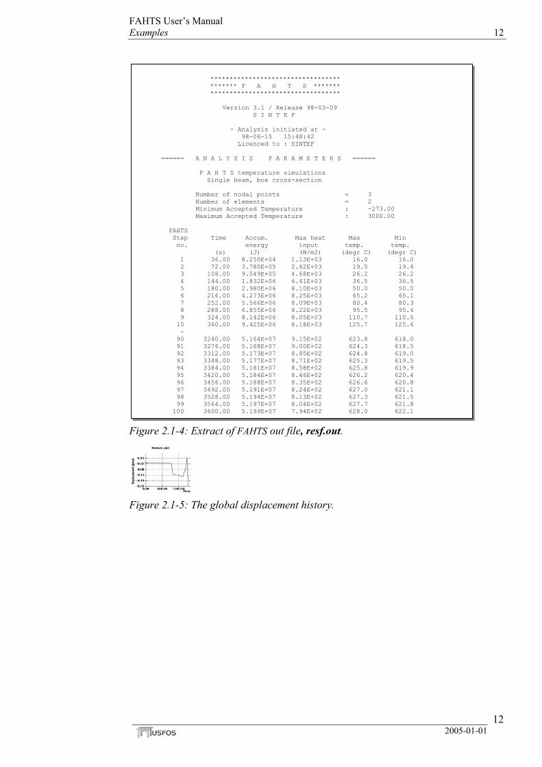
Problem: Structure with perpendicular radiation on the cantilever beam. The structure is exposed to radiation intensity of 10000 W/m2, which is constant. Solution: USERFIRE describes the problem by giving: - constant exposure; history = 0, - where the source is located; with X-coord. = 5 m, Y-coord. = 0 m and Z-coord. = 10000 m, - intensity at radius distance from the source; 10000 W/m2, and - reference radius from the source used to define the intensity; 10000 m. By setting a big distance, the rays, when they reach the structure, are almost parallel, and thereby perpendicular to the beam. The distance from the source to the structure is equal to the radius distance for the intensity. Thereby, the intensity at the structure is 10000 W/m2. Because the thermal elongation on top of the beam is bigger than under, the end of the beam will bent down. When the underside gets hotter and the temperature increment through the cross-section is reduced, the beam will bend up again and straighten out a bit.
HEAD F A H T S temperature simulation Beam + Column ' MOVIEPRI ! Override default mesh refinement. SHAPFACT ! Shape factor calc. is switched on. ' n_length n_circ TEMPMESH 2 16 ' '------------------------------------------------------------------------- ' USER DEFINED FIRE '---------- -------------------------------------------------------------- ' history x y z ref_intensity ref_radius USERFIRE ' '----------' '----------' TEMPSIM ' '----------' '----------' THERMPAR
Figure 2.7-
_________
-
0 5 0.0 10.0E3 10000.0 10.0E3
--------------------------------------------------------------- ANALYSIS TIME AND TEMPERATURE STEPS --------------------------------------------------------------- end-time (s) nstep resinc (s) 10800.0 300 900.0
--------------------------------------------------------------- THE MATERIAL'S THERMAL PARAMETERS --------------------------------------------------------------- id rho(kg/m3) c (J/kgK) k (W/mK) emiss 10000 7850.0 500.0 50.0 0.8
3: FAHTS Control file, fahts.fem.
________________________________________________________ 2005-01-01
22

FAHTS User’s Manual Examples 23
HEAD FAHTS example : Column and cantilever beam U S F O S SINTEF div of Structural Engineering '------------------------------------------------------------------------- ' AMOUNT OF INPUT AND OUTPUT PRINTED TO FILE '------------------------------------------------------------------------- ' inpri outpri termpri CPRINT 1 1 1 '------------------------------------------------------------------------- ' LOAD HISTORY AND DEFORMATION CONTROL '------------------------------------------------------------------------- ' nloads npostp mxpstp mxpdis CUSFOS 30 15 1.00 0.05 ' lcomb lfact mxld nstep minstp 4 0.5 1.0 15 0.05 5 0.5 1.0 15 0.05 6 0.5 1.0 15 0.05 7 0.5 1.0 15 0.05 8 0.5 1.0 15 0.05 9 0.5 1.0 15 0.05 10 0.5 1.0 15 0.05 11 0.5 1.0 15 0.05 12 0.5 1.0 15 0.05 13 0.5 1.0 15 0.05 ' ' ncnods CNODES 1 ' nodex idof dfact 40 3 1. '------------------------------------------------------------------------- ' INELASTIC MATERIAL PROPERTIES '------------------------------------------------------------------------- ' matno E-mod poiss yield density therm. exp. MISOIEP 10000 210000.0E6 0.3 248.E6 7850.0 1.4E-05
Figure 2.7-4: USFOS Control file, usfos.fem.
_________________________________________________________________ 2005-01-01
23

FAHTS User’s Manual Examples 24
********************************** ******* F A H T S ******* ********************************** Version 3.1 / Release 98-03-09 S I N T E F F A H T S temperature simulation Beam + Column Number of nodal points = 17 Number of elements = 16 Minimum Accepted Temperature : -273.00 Maximum Accepted Temperature : 3000.00 FAHTS Step Time Accum. Max heat Max Min no. energy input temp. temp. (s) (J) (W/m2) (degr C) (degr C) 1 36.00 2.864E+06 7.85E+03 23.7 19.9 2 72.00 5.724E+06 7.82E+03 27.4 19.9 3 108.00 8.578E+06 7.80E+03 31.0 19.8 4 144.00 1.143E+07 7.77E+03 34.6 19.8 5 180.00 1.427E+07 7.75E+03 38.3 19.8 6 216.00 1.710E+07 7.72E+03 41.8 19.7 7 252.00 1.993E+07 7.70E+03 45.4 19.7 8 288.00 2.275E+07 7.67E+03 48.9 19.7 9 324.00 2.556E+07 7.64E+03 52.5 19.6 10 360.00 2.837E+07 7.61E+03 56.0 19.6 - - - 290 10440.00 4.057E+08 8.24E+02 323.6 18.9 291 10476.00 4.061E+08 8.22E+02 323.6 18.9 292 10512.00 4.066E+08 8.19E+02 323.7 18.9 293 10548.00 4.070E+08 8.17E+02 323.7 18.9 294 10584.00 4.074E+08 8.15E+02 323.8 18.8 295 10620.00 4.078E+08 8.13E+02 323.8 18.8 296 10656.00 4.082E+08 8.11E+02 323.9 18.8 297 10692.00 4.086E+08 8.09E+02 323.9 18.8 298 10728.00 4.091E+08 8.06E+02 323.9 18.8 299 10764.00 4.095E+08 8.04E+02 324.0 18.8 300 10800.00 4.099E+08 8.02E+02 324.0 18.8 ======== F A H T S A N A L Y S I S C O M P L E T E D ========
Figure 2.7-5: Extract of FAHTS out file, resf.out.
Figure 2.7-6: The global displacement's development over time.
_________________________________________________________________ 2005-01-01
24

FAHTS User’s Manual Examples 25
2.8 Cantilever beam exposed to two radiation sources.
Ex. 8: Steel Pipe Partly exp. Unprotected User source Radiation
Material: Steel. Structure: Cantilever beam, nodal force in node 40, full exposure, not insulated. Similar structure as in the previous example. This example shows the use of user defined radiation fields. The structure is modelled with three elements (with refinement) as shown in Figure 2.8-1.
Figure 2.8-1: Model of the structure, with node- and element numbers.
Figure 2.8-2: The global displacement history.
Column length : 10.000 m Diameter (outer) : 1.100 m Thickness : 0.020 m Beam length : 10.000 m Diameter (outer) : 1.000 m Thickness : 0.020 m
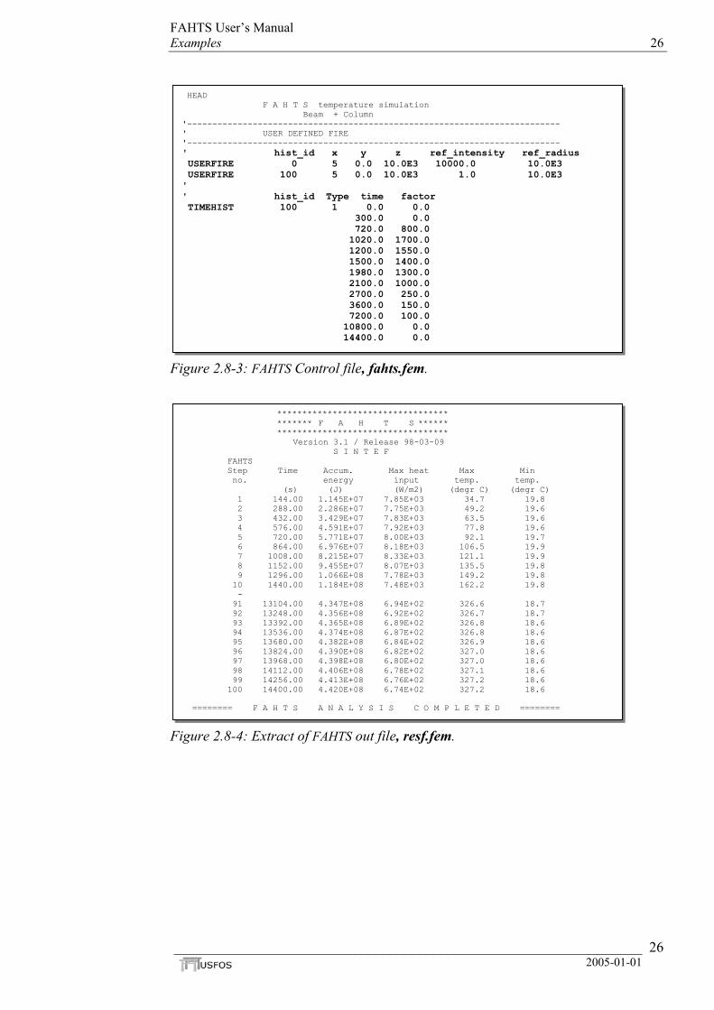
Yield stress : σ = 248 MPa Youngs modulus : E = 210000 MPa Nodal force, node 40 : 10 kN Fire load : User defined radiation field Problem: Two radiation sources, one is constant, the other is time dependent. Solution: Defines two sources with different time histories. The constant heat source is defined by giving it a hist_id 0. This tells that the source is constant. The reference intensity of the USERFIRE with hist_id 100 is set to 1.0. This is because the intensity is given in the TIMEHIST command. The ref_intensity factor is multiplied with the factor from TIMEHIST and the result is the total intensity at the given time.
_________________________________________________________________ 2005-01-01
25
FAHTS User’s Manual Examples 26
HEAD F A H T S temperature simulation Beam + Column '-------------------------------------------------------------------------- ' USER DEFINED FIRE '-------------------------------------------------------------------------- ' hist_id x y z ref_intensity ref_radius USERFIRE 0 5 0.0 10.0E3 10000.0 10.0E3 USERFIRE 100 5 0.0 10.0E3 1.0 10.0E3 ' ' hist_id Type time factor TIMEHIST 100 1 0.0 0.0 300.0 0.0 720.0 800.0 1020.0 1700.0 1200.0 1550.0 1500.0 1400.0 1980.0 1300.0 2100.0 1000.0 2700.0 250.0 3600.0 150.0 7200.0 100.0 10800.0 0.0 14400.0 0.0
Figure 2.8-3: FAHTS Control file, fahts.fem.
********************************** ******* F A H T S ****** ********************************** Version 3.1 / Release 98-03-09 S I N T E F FAHTS Step Time Accum. Max heat Max Min no. energy input temp. temp. (s) (J) (W/m2) (degr C) (degr C) 1 144.00 1.145E+07 7.85E+03 34.7 19.8 2 288.00 2.286E+07 7.75E+03 49.2 19.6 3 432.00 3.429E+07 7.83E+03 63.5 19.6 4 576.00 4.591E+07 7.92E+03 77.8 19.6 5 720.00 5.771E+07 8.00E+03 92.1 19.7 6 864.00 6.976E+07 8.18E+03 106.5 19.9 7 1008.00 8.215E+07 8.33E+03 121.1 19.9 8 1152.00 9.455E+07 8.07E+03 135.5 19.8 9 1296.00 1.066E+08 7.78E+03 149.2 19.8 10 1440.00 1.184E+08 7.48E+03 162.2 19.8 - 91 13104.00 4.347E+08 6.94E+02 326.6 18.7 92 13248.00 4.356E+08 6.92E+02 326.7 18.7 93 13392.00 4.365E+08 6.89E+02 326.8 18.6 94 13536.00 4.374E+08 6.87E+02 326.8 18.6 95 13680.00 4.382E+08 6.84E+02 326.9 18.6 96 13824.00 4.390E+08 6.82E+02 327.0 18.6 97 13968.00 4.398E+08 6.80E+02 327.0 18.6 98 14112.00 4.406E+08 6.78E+02 327.1 18.6 99 14256.00 4.413E+08 6.76E+02 327.2 18.6 100 14400.00 4.420E+08 6.74E+02 327.2 18.6 ======== F A H T S A N A L Y S I S C O M P L E T E D ========
Figure 2.8-4: Extract of FAHTS out file, resf.fem.
_________________________________________________________________ 2005-01-01
26

FAHTS User’s Manual Examples 27
2.9 Simple portal frame. Key words:
Ex. 9: Steel I-prof Fully exp. Unprotected User source Temp. hist.
Material: Steel. Structure: Simple frame, nodal forces in nodes 11 and 12, distributed load on the
beam, temperature rise in the environment. Not protected. This example shows the use of user defined constant temperature history. The structure is modelled with elements as shown in Figure 2.9-1.
Figure 2.9-1: Structural model. Figure 2.9-2: Deformed model.
Column length : 3.500 m ight : 0.206 m width : 0.204 m Beam length : 5.500 m height : 0.304 m width : 0.165 m Yield stress : σ = 275 MPa Youngs modulus : E = 205000 MPa Nodal forces:
node 11: 500 kN node 12: 500 kN Distributed force
beam : 25.4 kN/m Heat source : User defined temperature history
_________________________________________________________________ 2005-01-01
27

FAHTS User’s Manual Examples 28
Problem: Constant temperature in the environment around the structure. Solution: USERTEMP describes the number of the temperature/time history to be used, hist_id = 0 (constant time history). The field_temp is set to 600 Celsius degrees, which is the temperature in the environment.
HEAD F A H T S temperature simulation Simple Portal Frame MOVIEPRI '-------------------------------------------------------------------------- ' TYPE OF FIRE AND EXPOSURE '-------------------------------------------------------------------------- ' initemp INITEMP 20.0 ' hist_id field_temp USERTEMP 0 600 '-------------------------------------------------------------------------- ' ANALYSIS TIME AND TEMPERATURE STEPS '-------------------------------------------------------------------------- ' end-time (s) nstep resinc (s) TEMPSIM 7200.0 50 120.0 '-------------------------------------------------------------------------- ' THE MATERIAL'S THERMAL PARAMETERS '-------------------------------------------------------------------------- ' mat_id rho(kg/m3) c (J/kgK) k (W/mK) emiss convection THERMPAR 1 7850.0 450.0 54.0 0.8 20 ' ' mat_id rho(kg/m3) c (J/kgK) k (W/mK) dummy dummy INSIDPAR 1 1.273 0.7 0.0 0.0 0.0
Figure 2.9-3: FAHTS Control file, fahts.fem.
HEAD Portal Frame U S F O S progressive collapse analysis NUS/ SINTEF Structural Engineering TMPLOCON 1 BANANA STEELTDEP ! Temperature dependent material properties, reduction. ' rest. xfos out-file CSAVE 0 -10 -50 '-------------------------------------------------------------------------- ' LOAD HISTORY AND DEFORMATION CONTROL '-------------------------------------------------------------------------- ' nloads npostp mxpstp mxpdis CUSFOS 10 100 1.00 0.05 ' lcomb lfact mxld nstep minstp 1 0.5 1.0 10 0.01 ! Dead weight 4 0.05 1.0 100 0.01 ! Fire load 5 0.05 1.0 100 0.01 ! Fire load 6 0.02 1.0 100 0.01 ! Fire load 7 0.01 1.0 100 0.01 ! Fire load 8 0.01 1.0 100 0.01 ! Fire load 9 0.01 1.0 100 0.01 ! Fire load 10 0.01 1.0 100 0.01 ! Fire load - - 23 0.01 1.0 100 0.01 ! Fire load ' ' ncnods CNODES 1 ' nodex idof dfact 11 1 1. 11 2 1. 11 3 1. '-------------------------------------------------------------------------- ' INELASTIC MATERIAL PROPERTIES '-------------------------------------------------------------------------- ' matno E-mod poiss yield density therm. exp. MISOIEP 1 205000.0E6 0.3 275.0E6 7850 1.4E-05
Figure 2.9-4: USFOS Control file, usfos.fem.
_________________________________________________________________ 2005-01-01
28

FAHTS User’s Manual Examples 29
********************************** ******* F A H T S ****** ********************************** Version 3.1 / Release 98-03-09 S I N T E F FAHTS Step Time Accum. Max heat Max Min no. energy input temp. temp. (s) (J) (W/m2) (degr C) (degr C) 1 144.00 8.437E+07 7.53E+04 434.7 257.2 2 288.00 1.537E+08 5.59E+04 709.6 513.5 3 432.00 1.777E+08 1.67E+04 750.8 667.0 4 576.00 1.583E+08 -2.14E+04 664.3 526.9 5 720.00 1.406E+08 1.85E+04 595.2 472.2 6 864.00 1.473E+08 2.80E+04 604.7 560.3 7 1008.00 1.590E+08 1.06E+04 667.1 582.6 8 1152.00 1.585E+08 3.52E+03 633.7 609.1 9 1296.00 1.520E+08 -2.60E+03 613.1 550.0 10 1440.00 1.517E+08 1.31E+04 601.0 564.2 - 41 5904.00 1.545E+08 4.38E+01 600.0 599.9 42 6048.00 1.545E+08 2.69E+01 600.1 600.0 43 6192.00 1.545E+08 4.69E-02 600.1 600.0 44 6336.00 1.545E+08 -1.63E-02 600.0 600.0 45 6480.00 1.545E+08 1.19E+01 600.0 599.9 46 6624.00 1.545E+08 1.77E+01 600.0 600.0 47 6768.00 1.545E+08 8.95E-02 600.0 600.0 48 6912.00 1.545E+08 9.22E-03 600.0 600.0 49 7056.00 1.545E+08 -2.65E-03 600.0 600.0 50 7200.00 1.545E+08 8.95E+00 600.0 600.0 ======== F A H T S A N A L Y S I S C O M P L E T E D ========
Figure 2.9-5: Extract of result file from FAHTS analysis, resf.out.
_________________________________________________________________ 2005-01-01
29

FAHTS User’s Manual Examples 30
2.10 Simple portal frame. Key words:
Ex. 10: Steel I-prof Fully exp. Unprotected User source Temp. hist.
Material: Steel. Structure: Simple frame, nodal forces in nodes 11 and 12, distributed load on the
beam, temperature rise in the environment. Not protected. This example shows the use of user defined temperature history. The structure is modelled with elements as shown in Figure 2.10-1.
Figure 2.10-1: Structural model. Figure 2.10-2: Deformed model.
Column length : 3.500 m height : 0.206 m width : 0.204 m Beam length : 5.500 m height : 0.304 m width : 0.165 m Yield stress : σ = 275 MPa Youngs modulus : E = 205000 MPa Nodal forces:
node 11: 500 kN node 12: 500 kN Distributed force:
beam : 25.4 kN/m Heat source : User defined temperature history
_________________________________________________________________ 2005-01-01
30

FAHTS User’s Manual Examples 31
Problem: Increasing temperature in the environment around the structure. Solution: USERTEMP describes the number of the temperature/time history to be used, hist_id = 100, and a factor, field_temp, to be multiplied with the factor from TIMEHIST to give the temperature. The field_temp factor is set to 1.0 in this example because the factor in TIMEHIST describes the temperature in Celsius degrees. This is the recommended way to do it, because of the readability. TIMEHIST sets the variation of the temperature over time for the specific history. The factor Type defines the type of points on the curve that are used. The number 1 defines discreet points. USERTEMP can be extended if the heat source only affects a part of the structure. See the following example.
HEAD F A H T S temperature simulation Simple Portal Frame MOVIEPRI '-------------------------------------------------------------------------- ' TYPE OF FIRE AND EXPOSURE '-------------------------------------------------------------------------- ' initemp I' NITEMP 20.0
' hist_id field_temp USERTEMP 100 1.0 ' ' hist_id Type time factor TIMEHIST 100 1 0.0 20.0 1500.0 697.0 2160.0 734.0 2940.0 697.0 4560.0 514.0 12960.0 20.0 100000.0 20.0 '-------------------------------------------------------------------------- ' ANALYSIS TIME AND TEMPERATURE STEPS '-------------------------------------------------------------------------- ' end-time (s) nstep resinc (s) TEMPSIM 14400.0 200 360.0 '-------------------------------------------------------------------------- ' THE MATERIAL'S THERMAL PARAMETERS '-------------------------------------------------------------------------- ' mat_id rho(kg/m3) c (J/kgK) k (W/mK) emiss convection THERMPAR 1 7850.0 450.0 54.0 0.8 20 ' ' mat_id rho(kg/m3) c (J/kgK) k (W/mK) dummy dummy INSIDPAR 1 1.273 0.7 0.0 0.0 0.0
Figure 2.10-3: FAHTS Control file, fahts.fem.
_________________________________________________________________ 2005-01-01
31

FAHTS User’s Manual Examples 32
HEAD Portal Frame U S F O S progressive collapse analysis NUS/ SINTEF Structural Engineering TMPLOCON 1 BANANA STEELTDEP ! Temperature dependent material properties, reduction. ' rest. xfos out-file CSAVE 0 -10 -50 '-------------------------------------------------------------------------- ' LOAD HISTORY AND DEFORMATIONCONTROL '-------------------------------------------------------------------------- ' nloads npostp mxpstp mxpdis CUSFOS 10 100 1.00 0.05 ' lcomb lfact mxld nstep minstp 1 0.5 1.0 10 0.01 ! Dead weight ' 4 0.05 1.0 100 0.01 ! Fire load 5 0.05 1.0 100 0.01 ! Fire load 6 0.02 1.0 100 0.01 ! Fire load 7 0.01 1.0 100 0.01 ! Fire load 8 0.01 1.0 100 0.01 ! Fire load 9 0.01 1.0 100 0.01 ! Fire load 10 0.01 1.0 100 0.01 ! Fire load 11 0.01 1.0 100 0.01 ! Fire load 12 0.01 1.0 100 0.01 ! Fire load 13 0.01 1.0 100 0.01 ! Fire load ' ' ncnods CNODES 1 ' nodex idof dfact 11 1 1. 11 2 1. 11 3 1. '-------------------------------------------------------------------------- ' INELASTIC MATERIAL PROPERTIES '-------------------------------------------------------------------------- ' matno E-mod poiss yield density therm. exp. MISOIEP 1 205000.0E6 0.3 275.0E6 7850 1.4E-05
Figure 2.10-4: USFOS Control file, usfos.fem.
********************************** ******* F A H T S ****** ********************************** FAHTS Step Time Accum. Max heat Max Min no. energy input temp. temp. (s) (J) (W/m2) (degr C) (degr C) 1 72.00 4.624E+05 1.65E+03 22.3 21.2 2 144.00 1.859E+06 3.35E+03 29.2 25.2 3 216.00 4.190E+06 5.05E+03 40.2 32.1 4 288.00 7.443E+06 6.76E+03 55.3 42.1 5 360.00 1.162E+07 8.52E+03 74.2 55.3 6 432.00 1.673E+07 1.03E+04 96.9 71.8 7 504.00 2.280E+07 1.22E+04 123.6 91.8 8 576.00 2.985E+07 1.42E+04 154.2 115.3 9 648.00 3.789E+07 1.62E+04 188.6 142.4 10 720.00 4.694E+07 1.83E+04 226.8 173.3 - 190 13680.00 2.827E+06 -3.53E+02 33.6 26.2 191 13752.00 2.529E+06 -3.06E+02 32.3 25.4 192 13824.00 2.264E+06 -2.65E+02 31.1 24.6 193 13896.00 2.027E+06 -2.29E+02 30.0 24.0 194 13968.00 1.816E+06 -1.98E+02 29.1 23.5 195 14040.00 1.628E+06 -1.72E+02 28.2 23.0 196 14112.00 1.459E+06 -1.49E+02 27.4 22.6 197 14184.00 1.309E+06 -1.29E+02 26.7 22.3 198 14256.00 1.174E+06 -1.12E+02 26.0 22.0 199 14328.00 1.054E+06 -9.69E+01 25.5 21.7 200 14400.00 9.458E+05 -8.40E+01 24.9 21.5 ======== F A H T S A N A L Y S I S C O M P L E T E D ========
Figure 2.10-5: Extract of result file from FAHTS analysis, resf.out.
_________________________________________________________________ 2005-01-01
32

FAHTS User’s Manual Examples 33
2.11 3 Bay and 3 Storey frame. Key words:
Ex. 11: Steel I-prof Partly exp. Unprotected User source Temp. hist.
Material: Steel. Structure: 3 Bay x 3 Storey frame, nodal forces on top of the columns,
distributed load on all horizontal elements, heat source placed on the first floor in the first bay. Not protected.
This example shows the use of user defined temperature history, and the heat source location. The structure is modelled as shown in Figure 2.11-1.
Figure 2.11-1: Structural model.
Column length : 3.500 m height : 0.206 m width : 0.204 m Beam length : 5.500 m height : 0.304 m width : 0.165 m Nodal forces: end columns : 75 kN mid columns : 151 kN Distributed forces: all horizontal elements: 25.4 kN/m Heat source : User defined temperature history
_________________________________________________________________ 2005-01-01
33

FAHTS User’s Manual Examples 34
Problem: 3 Bay x 3 Storey frame, with heat source on ground level in first bay. Solution: This example is similar to the previous, except from a few new conditions in the USERTEMP command. Gas_Abs is always set to 1.0. The next conditions define which part of the structure that is exposed to the heat. There are three ways to do this, and they are described in the FAHTS User's Manual. The command is called LIMITMOD, but can be integrated in USERTEMP, as in this example. The Lim_Type can be 1, -1, 2, -2, 3 or -3. For more information about the difference here, see FAHTS User's Manual. In this example the Lim_Type is 1. I.e., the part of the structure, which is of interest with respect on temperature distribution, is extracted from the structure with a box defined by two points. When Lim_Type is set to 1, all the elements on the inside of the box are included in the transient heat transfer analysis. The next numbers are the co-ordinates of the two points of the box. To obtain a good readability of the Control file, the co-ordinates of the second point are written under the co-ordinates of the first point. If the heat source is radiation, the command LIMTFIRE is used to extract a part of the structure. See USFOS User's Manual.
_________________________________________________________________ 2005-01-01
34

FAHTS User’s Manual Examples 35
HEAD 3 Bay x 3 storey frame, Partly Exposed. F A H T S temperature simulation NUS/SINTEF Structural Engineering MOVIEPRI '------------------------------------------------------------------------- ' PROFILE MESH '------------------------------------------------------------------------- ' n_length n_web n_top n_bott MESHIPRO 8 1 2 2 MESHIPRO 8 6 6 6 1112 111 212 '------------------------------------------------------------------------- ' HEAT SOURCE '------------------------------------------------------------------------- ' initemp INITEMP 20.0 ' ' hist_id field_temp Gas_Abs Lim_Type x y z USERTEMP 100 1.0 1.0 1 -1.0 -1.0 -1.0 1.0 5.6 3.6 ' ' hist_id Type time factor TIMEHIST 100 1 0.0 20.0 1500.0 697.0 2160.0 734.0 2940.0 697.0 4560.0 514.0 12960.0 20.0 100000.0 20.0 '------------------------------------------------------------------------- ' EXPOSURE AND PROTECTION '------------------------------------------------------------------------- ' * Exposure * * Passive Fire Protection * ' Geo_Typ top Web bott top Web bott EXP_ELEM 2 2 3 3 0 0 0 ' List of elements 1112 ! Floor Beam, first floor, first bay ' ' * Exposure * * Passive Fire Protection * ' Geo_Typ top Web bott top Web bott EXP_ELEM 2 3 3 2 0 0 0 ' List of elements 111 ! First bay, column to the left ' ' * Exposure * * Passive Fire Protection * ' Geo_Typ top Web bott top Web bott EXP_ELEM 2 2 3 3 0 0 0 ' List of elements 212 ! First bay, column to the right '------------------------------------------------------------------------- ' ANALYSIS TIME AND TEMPERATURE STEPS '------------------------------------------------------------------------- ' end-time (s) nstep resinc (s) TEMPSIM 7200.0 200 360.0 '------------------------------------------------------------------------- ' THE MATERIAL'S THERMAL PARAMETERS '------------------------------------------------------------------------- ' id rho(kg/m3) c (J/kgK) k (W/mK) emiss convection THERMPAR 1 7850.0 450.0 54.0 0.8 20 THERMPAR 2 7850.0 450.0 54.0 0.8 20 ' ' id rho(kg/m3) c (J/kgK) k (W/mK) dummy dummy INSIDPAR 1 1.273 0.7 0.0 0 0
Figure 2.11-2: FAHTS Control file, fahts.fem.
_________________________________________________________________ 2005-01-01
35

FAHTS User’s Manual Examples 36
********************************** ******* F A H T S ****** ********************************** Version 3.1 / Release 98-03-09 S I N T E F - Analysis initiated at - 98-06-25 09:28:25 Licenced to : SINTEF FAHTS Step Time Accum. Max heat Max Min no. energy input temp. temp. (s) (J) (W/m2) (degr C) (degr C) 1 36.00 9.663E+04 8.11E+02 20.7 20.0 2 72.00 3.870E+05 1.64E+03 22.8 19.8 3 108.00 8.698E+05 2.46E+03 26.3 19.6 - 198 7128.00 8.572E+07 1.03E+04 450.2 2.1 199 7164.00 8.520E+07 1.02E+04 447.8 2.1 200 7200.00 8.469E+07 1.01E+04 445.3 2.0 ======== F A H T S A N A L Y S I S C O M P L E T E D =======
Figure 2.11-3: Extract of FAHTS out file, resf.out.
_________________________________________________________________ 2005-01-01
36

FAHTS User’s Manual Examples 37
2.12 9 Bay and 3 Storey frame.
Ex. 12: Steel I-prof Partly exp. Unprotected User source Temp. hist.
Material: Steel. Structure: 9 Bay x 3 Storey frame, nodal forces on top of all columns, distributed
load on all horizontal elements, heat source placed on the second floor in bay No 5. Partly protected.
This example shows the use of user defined temperature history. The structure is modelled with nodes as shown in .
Figure 2.12-1: Structural model.
Figure 2.12-2: Deformed model.
Column length : 3.600 m height : 0.276 m width : 0.261 m Beam length : 8.000 m height : 0.602 m width : 0.228 m Yield stress : σ = 275 MPa Youngs modulus : E = 205000 MPa Nodal forces:
node 41 and 50: 475.2 kN node 42-49 : 950.4 kN Distributed forces: on all beams : 59.4 kN/m Heat source : User defined temperature history
_________________________________________________________________ 2005-01-01
37

FAHTS User’s Manual Examples 38
Problem: 9 Bay x 3 Storey frame. Several different heat sources with temperature/time-histories. Solution: Each heat source must be described with a USERTEMP commando line and a time history, TIMEHIST. Each source gets an identification number, which is equal for the commands, USERTEMP and TIMEHIST. The sources are defined in the same way as the source in the previous example.
HEAD 9 Bay x Four storey frame, Partly Exposed. F A H T S temperature simulation NUS/SINTEF Structural Engineering ' MOVIEPRI GLVIEW '-------------------------------------------------------------------------- ' PROFILE MESH '-------------------------------------------------------------------------- ' n_length n_web n_top n_bott MESHIPRO 8 1 2 2 '-------------------------------------------------------------------------- ' HEAT SOURCE '-------------------------------------------------------------------------- ' initemp INITEMP 20.0 ' ' hist field_temp Gas_Abs Lim_Type x y z USERTEMP 31 1.0 1.0 1 -1.0 15.0 3.5 1.0 25.0 7.3 ' ' hist field_temp Gas_Abs Lim_Type x y z USERTEMP 41 1.0 1.0 1 -1.0 23.0 3.5 1.0 33.0 7.3 ' ' hist field_temp Gas_Abs Lim_Type x y z USERTEMP 51 1.0 1.0 1 -1.0 31.0 3.5 1.0 41.0 7.3 ' ' hist field_temp Gas_Abs Lim_Type x y z USERTEMP 61 1.0 1.0 1 -1.0 39.0 3.5 ' ' USERTEMP ' ' TIMEHIST TIMEHIST TIMEHIST
_________
1.0 49.0 7.3
hist field_temp Gas_Abs Lim_Type x y z 71 1.0 1.0 1 -1.0 47.0 3.5 1.0 57.0 7.3
id Type time factor 31 1 0.0 20.0 4000.0 20.0 5500.0 697.0 6160.0 734.0 6940.0 697.0 8560.0 514.0 16960.0 20.0 100000.0 20.0 41 1 0.0 20.0 2000.0 20.0 3500.0 697.0 4160.0 734.0 4940.0 697.0 6560.0 514.0 14960.0 20.0 100000.0 20.0 51 1 0.0 20.0 1500.0 697.0 2160.0 734.0 2940.0 697.0 4560.0 514.0 12960.0 20.0 100000.0 20.0
________________________________________________________ 2005-01-01
38

FAHTS User’s Manual Examples 39
' ' id Type time factor TIMEHIST 61 1 0.0 20.0 2000.0 20.0 3500.0 697.0 4160.0 734.0 4940.0 697.0 6560.0 514.0 14960.0 20.0 100000.0 20.0 ' ' id Type time factor TIMEHIST 71 1 0.0 20.0 4000.0 20.0 5500.0 697.0 6160.0 734.0 6940.0 697.0 8560.0 514.0 16960.0 20.0 100000.0 20.0 '-------------------------------------------------------------------------- ' ANALYSIS TIME AND TEMPERATURE STEPS '-------------------------------------------------------------------------- ' end-time (s) nstep resinc (s) TEMPSIM 7200.0 200 360.0 '-------------------------------------------------------------------------- ' THE MATERIAL'S THERMAL PARAMETERS '-------------------------------------------------------------------------- ' id rho(kg/m3) c (J/kgK) k (W/mK) emiss convection THERMPAR 1 7850.0 450.0 54.0 0.8 20 THERMPAR 2 7850.0 450.0 54.0 0.8 20 THERMPAR 1000 7850.0 450.0 54.0 0.8 20 ' ' id rho(kg/m3) c (J/kgK) k (W/mK) dummy dummy INSIDPAR 1 1.273 0.7 0.0 0 0 ' ' id type K Emiss INSULPAR 10 1 5.0 0.8 '-------------------------------------------------------------------------- ' EXPOSURE AND PROTECTION '-------------------------------------------------------------------------- ' Insulation_ID ELMINSUL 10 1121 1222 1323 1424 1525 1626 1727 1828 1929 2030
Figure 2.12-3: FAHTS Control file, fahts.fem.
_________________________________________________________________ 2005-01-01
39

FAHTS User’s Manual Examples 40
HEAD 9 Bay x 3 Storey frame U S F O S progressive collapse analysis NUS/SINTEF Structural Engineering TMPLOCON 1 BANANA STEELTDEP ! Temperature dependent material properties DETEROFF ! Determinant check switched off CMAXSTEP 2000 ' ' rest. xfos out-file CSAVE 0 -25 -50 '------------------------------------------------------------------------- ' LOAD HISTORY AND DEFORMATION CONTROL '------------------------------------------------------------------------- ' nloads npostp mxpstp mxpdis CUSFOS 10 100 1.00 0.05 ' lcomb lfact mxld nstep minstp 1 0.1 3.0 50 0.01 ! Dead weight 4 0.04 1.0 100 0.01 ! Fire load 5 0.04 1.0 100 0.01 ! Fire load 6 0.04 1.0 100 0.01 ! Fire load 7 0.04 1.0 100 0.01 ! Fire load 8 0.04 1.0 100 0.01 ! Fire load 9 0.04 1.0 100 0.01 ! Fire load 10 0.04 1.0 100 0.01 ! Fire load 11 0.04 1.0 100 0.01 ! Fire load 12 0.04 1.0 100 0.01 ! Fire load 13 0.04 1.0 100 0.01 ! Fire load 14 0.04 1.0 100 0.01 ! Fire load 15 0.04 1.0 100 0.01 ! Fire load 16 0.04 1.0 100 0.01 ! Fire load 17 0.04 1.0 100 0.01 ! Fire load 18 0.04 1.0 100 0.01 ! Fire load 19 0.04 1.0 100 0.01 ! Fire load 20 0.04 1.0 100 0.01 ! Fire load 21 0.04 1.0 100 0.01 ! Fire load 22 0.04 1.0 100 0.01 ! Fire load 23 0.04 1.0 100 0.01 ! Fire load ' ncnods CNODES 1 ' nodex idof dfact 35 2 1. 35 3 1. 36 2 1. 36 3 1. '-------------------------------------------------------------------------- ' INELASTIC MATERIAL PROPERTIES '---------- --------------------------------------------------------------- ' matno E-mod poiss yield density therm. exp. MISOIEP 1 205000.0E6 0.3 275.0E6 7850 1.4E-05 MISOIEP '' ' MREF
Figure 2.12
FAH St n 19 20 ========
Figure 2.12
_________
-
2 205000.0E6 0.3 275.0E6 7850 1.4E-05 X Y Z Mx My Mz 1000 99 99 99 99 1002 99 ! Non linear Flexible Connection-4: USFOS Control file, usfos.fem.
********************************** ******* F A H T S ****** **********************************
TS ep Time Accum. Max heat Max Min o. energy input temp. temp. (s) (J) (W/m2) (degr C) (degr C) 1 36.00 1.761E+05 8.11E+02 20.4 20.0 2 72.00 8.611E+05 1.64E+03 21.6 19.8
9 7164.00 2.301E+09 1.36E+04 799.8 -13.9 0 7200.00 2.292E+09 1.34E+04 795.8 -12.4 F A H T S A N A L Y S I S C O M P L E T E D ========
-5: Extract of FAHTS out file, resf.out.
________________________________________________________ 2005-01-01
40

FAHTS User’s Manual Examples 41
2.13 Arched framework exposed to radiation and heat increment. Key words:
Ex. 13: Steel I-prof Partly exp. Unprotected Radiation Temp. hist.
Material: Steel. Structure: Arched framework, exposed to both radiation and environmental
temperature increment, not protected. This example shows the use of a combination of user defined temperature histories and radiation. The structure is modelled as shown in Figure 2.13-1.
Figure 2.13-1: Structural model.
Yield stress : σ = 275 MPa Youngs modulus : E = 205000 MPa Heat source : User defined radiation and temperature history Problem: Structure with both increasing environmental temperature, and radiation. Several sources. Solution: Define all radiation sources like in 2.8, and all temperature sources like in 2.12. In this example, also the radiation sources are time dependent. This is defined in the same way as temperature fields, by giving a factor for the variation of the intensity over time. The ref_intensity factor from USERFIRE is multiplied with the factor from TIMEHIST, and results in the total intensity at the given time.
_________________________________________________________________ 2005-01-01
41

FAHTS User’s Manual Examples 42
HEAD F A H T S temperature simulation Tuas Checkpoint, SINGAPORE Car Fire Simulations MOVIEPRI ' N_Lengt nside ntop nbot MESHIPRO 4 1 2 2 '------------------------------------------------------------------------- ' HEAT SOURCE '------------------------------------------------------------------------- ' initemp INITEMP 30.0 ' hist_id x y z ref_intensity ref_radius USERFIRE 1000 11 -1 1 0.2 0.4 USERFIRE 1005 16 -1 1 0.2 0.4 USERFIRE 1010 11 1 1 0.2 0.4 U'
SERFIRE 1010 16 1 1 0.2 0.4
' hist_id field_temp Gas_Abs Lim_Type x1 y1 z1 x2 y2 z2 USERTEMP 100 100 1.0 USERTEMP 100 300.0 1.0 1 4 -5 0 22 5 20 USERTEMP 100 600.0 1.0 1 8 -5 0 20 5 7 USERTEMP 100 550.0 1.0 1 9 -5 7 18 5 20' ' hist_id Type time factor TIMEHIST 100 1 0.0 0.0 300.0 0.8 720.0 1.0 1980.0 0.7 2100.0 0.3 2700.0 0.1 3600.0 0.0 7200.0 0.0 TIMEHIST 1000 1 0.0 800.0E3 300.0 1700.0E3 720.0 1250.0E3 1020.0 1400.0E3 1200.0 1300.0E3 1500.0 1750.0E3 1980.0 1000.0E3 2100.0 500.0E3 2700.0 250.0E3 3600.0 150.0E3 7200.0 100.0E3 TIMEHIST 1005 1 0.0 800.0E3 300.0 1700.0E3 720.0 1250.0E3 1020.0 1400.0E3 1200.0 1300.0E3 1500.0 1750.0E3 1980.0 1000.0E3 2100.0 500.0E3 2700.0 250.0E3 3600.0 150.0E3 7200.0 100.0E3 TIMEHIST 1010 1 0.0 800.0E3 300.0 1700.0E3 720.0 1250.0E3 1020.0 1400.0E3 1200.0 1300.0E3 1500.0 1750.0E3 1980.0 1000.0E3 2100.0 500.0E3 2700.0 250.0E3 3600.0 150.0E3 7200.0 100.0E3 '-------------------------------------------------------------------------- ' ANALYSIS TIME, TEMPERATURE STEPS AND THERMAL PARAMETERS '-------------------------------------------------------------------------- ' end-time (s) nstep resinc (s) TEMPSIM 1800.0 50 360.0 ' ' mat_id rho(kg/m3) c (J/kgK) k (W/mK) emiss convection THERMPAR 1 7850.0 450.0 54.0 0.8 20 ' ' mat_id rho(kg/m3) c (J/kgK) k (W/mK) dummy dummy INSIDPAR 1 1.273 0.7 0.0 0.0 0.0
Figure 2.13-2: FAHTS Control file, fahts.fem.
_________________________________________________________________ 2005-01-01
42

FAHTS User’s Manual Examples 43
********************************** ******* F A H T S ****** ********************************** FAHTS Step Time Accum. Max heat Max Min no. energy input temp. temp. (s) (J) (W/m2) (degr C) (degr C) 1 36.00 -1.144E+06 3.25E+03 32.3 28.8 2 72.00 3.323E+06 6.69E+03 38.1 28.0 3 108.00 1.387E+07 1.05E+04 47.6 27.6 4 144.00 3.097E+07 1.49E+04 61.3 27.5 5 180.00 5.523E+07 2.00E+04 79.5 27.7 6 216.00 8.746E+07 2.60E+04 103.1 28.2 7 252.00 1.286E+08 3.31E+04 132.9 29.0 8 288.00 1.799E+08 4.15E+04 169.7 30.1 9 324.00 2.383E+08 4.45E+04 211.5 31.2 10 360.00 2.978E+08 4.40E+04 253.7 32.5 - 41 1476.00 8.384E+08 1.99E+03 583.5 70.1 42 1512.00 8.321E+08 1.88E+03 579.4 71.1 43 1548.00 8.256E+08 1.62E+03 575.0 71.9 44 1584.00 8.188E+08 1.39E+03 570.4 72.7 45 1620.00 8.118E+08 1.20E+03 565.6 73.4 46 1656.00 8.046E+08 1.05E+03 560.6 74.0 47 1692.00 7.972E+08 9.14E+02 555.5 74.6 48 1728.00 7.897E+08 7.95E+02 550.3 75.0 49 1764.00 7.821E+08 6.85E+02 545.1 75.4 50 1800.00 7.743E+08 5.80E+02 539.8 75.7 ======== F A H T S A N A L Y S I S C O M P L E T E D ========
Figure 2.13-3: Extract of result file from FAHTS analysis, resf.fem.
_________________________________________________________________ 2005-01-01
43

FAHTS User’s Manual Examples 44
2.14 Single frame exposed to pool fire placed between columns. Key words:
Ex. 14: Steel Pipe Fully exp. Unprotected Kameleon Static ana.
Material: Steel. Structure: Single frame, node load in node 40, full exposure, unprotected.
The two horizontal elements are not connected at the middle. This example shows structures with thermal expansion. The frame is modelled with nodes as shown in Figure 2.14-1.
Figure 2.14-1: Structural model with node and element numbers.
Figure 2.14-2: Deformed model.
Column length : 9.990 m Diameter (outer) : 1.000 m Thickness : 0.020 m Beam length : 7.960 m Diameter (outer) : 1.000 m Thickness : 0.020 m
Yield stress : σ = 248 MPa Youngs modulus : E = 210000 MPa Fire load : From FIREINT database
_________________________________________________________________ 2005-01-01
44

FAHTS User’s Manual Examples 45
Problem: Beam not connected at the middle. Solution: Four nodes; 20, 40, 4 and 2 defines the beam. A beam not connected at the middle will have to be composed of the two elements 20-40 and 4-2. There is no connection between the nodes 40 and 4, and the beam is therefore not connected at the middle. The frame will be free to expand because of the increasing temperature, and will not obtain any inner forces or stress.
HEAD ' SESAM ' '-------------------------------------------------------------------------- ' NODAL DATA '-------------------------------------------------------------------------- ' node-id x y z boun.cond. ' ix iy iz irx iry irz NODE 10 -3.99 0.0 0.01 1 1 1 1 1 1 NODE 20 -3.99 0.0 9.45 NODE 30 -3.99 0.0 9.99 NODE 40 -0.01 0.0 9.45 ' NODE 1 3.99 0.0 0.01 1 1 1 1 1 1 NODE 2 3.99 0.0 9.45 NODE 3 3.99 0.0 9.99 NODE 4 0.01 0.0 9.45 ' ' load-case node-no Fx Fy Fz Mx My Mz NODELOAD 1 40 0.0 0.0 -1000.0 ' '--------------------------------------------------------------------------- ' ELEMENT DATA '---------------------------------------------------------------------' elem-ID np1 np2 mater geom lcoor
------
BEAM 1020 10 20 10000 100 1 BEAM 2030 20 30 10000 100 1 BEAM 2040 20 40 10000 100 1 ' BEAM 12 1 2 10000 100 1 BEAM 23 2 3 10000 100 1 BEAM 24 2 4 10000 100 1 ' ' lco-no dx dy dz UNITVEC 1 -1000.0 0.0 100.0 ' REFINE 8 1020 12 REFINE 5 2040 24 ' '--------------------------------------------------------------------------- ' CROSS-SECTION DATA '--------------------------------------------------------------------------- ' geo_no Do Thick PIPE 100 1.000 0.020 ' '--------------------------------------------------------------------------- ' MATERIAL PROPERTIES '--------------------------------------------------------------------------- ' mat_no E-mod Poiss MISOSEL 10000 210000.0E6 0.3
Figure 2.14-3: Structure file, stru.fem.
_________________________________________________________________ 2005-01-01
45

FAHTS User’s Manual Examples 46
HEAD F A H T S temperature simulation Beam + Column TUBE - profile SHAPFACT ! Shape factor calc. is switched on. ' MOVIEPRI ! Override default mesh refinement. '------------------------------------------------------------------------- ' TYPE OF FIRE AND EXPOSURE '------------------------------------------------------------------------- FIREINT ! Fire scenario from FIREINT database. ' ' initemp INITEMP 10.0 '------------------------------------------------------------------------- ' ANALYSIS TIME AND TEMPERATURE STEPS '------------------------------------------------------------------------- ' end-time (s) nstep resinc (s) TEMPSIM 3600.0 100 360.0 '------------------------------------------------------------------------- ' THERMAL PARAMETERS OF MATERIAL AND INSULATION '------------------------------------------------------------------------- ' id rho(kg/m3) c (J/kgK) k (W/mK) emiss THERMPAR 10000 7850.0 500.0 50.0 0.8 ' ' id rho(kg/m3) c (J/kgK) INSIDPAR 1 1.273 0.7
Figure 2.14-4: FAHTS Control file, fahts.fem.
HEAD FAHTS example : Simple tubular frame, no connection mid span U S F O S SINTEF div of Structural Engineering ' '------------------------------------------------------------------------- ' AMOUNT OF INPUT AND OUTPUT PRINTED TO FILE '------------------------------------------------------------------------- ' inpri outpri termpri CPRINT 1 1 1 '------------------------------------------------------------------------- ' LOAD HISTORY AND DEFORMATION CONTROL '------------------------------------------------------------------------- ' nloads npostp mxpstp mxpdis CUSFOS 30 15 1.00 0.05 ' lcomb lfact mxld nstep minstp 4 0.5 1.0 15 0.05 5 0.5 1.0 15 0.05 6 0.5 1.0 15 0.05 7 0.5 1.0 15 0.05 8 0.5 1.0 15 0.05 9 0.5 1.0 15 0.05 10 0.5 1.0 15 0.05 11 0.5 1.0 15 0.05 12 0.5 1.0 15 0.05 13 0.5 1.0 15 0.05 ' ' ncnods CNODES 1 ' nodex idof dfact 40 3 1. ' '------------------------------------------------------------------------- ' MATERIAL PROPERTIES '------------------------------------------------------------------------- ' matno E-mod poiss yield density therm.exp. MISOIEP 10000 210000.0E6 0.3 248.E6 7850.0 1.4E-05
Figure 2.14-5: USFOS Control file, usfos.fem.
_________________________________________________________________ 2005-01-01
46

FAHTS User’s Manual Examples 47
********************************** ******* F A H T S ******* ********************************** FAHTS Step Time Accum. Max heat Max Min no. energy input temp. temp. (s) (J) (W/m2) (degr C) (degr C) 1 36.00 1.194E+05 2.00E+03 10.9 9.7 2 72.00 2.384E+05 2.00E+03 11.8 9.5 3 108.00 3.567E+05 1.99E+03 12.6 9.3 - 98 3528.00 1.527E+08 2.94E+03 186.9 8.7 99 3564.00 1.536E+08 2.93E+03 187.4 8.8 100 3600.00 1.546E+08 2.91E+03 187.9 8.9
Figure 2.14-6: Extract of FAHTS out file, resf.out.
Figure 2.14-7: The global displacement's development over time.
_________________________________________________________________ 2005-01-01
47

FAHTS User’s Manual Examples 48
2.15 Single frame exposed to pool fire placed between columns. Key words:
Ex. 15: Steel Pipe Fully exp. Unprotected Kameleon Temp. sim.
Material: Steel. Structure: Single frame, full exposure, unprotected. Similar structure as in the previous example, except from the two horizontal elements, which are connected at the middle. This example shows structures with thermal expansion. The frame is modelled with nodes as shown in Figure 2.15-1.
Figure 2.15-1: Structural model with node and element numbers.
Figure 2.15-2: Deformed model.
Problem: Simple frame, beam connected at the middle. Solution: Define elements between the nodes 2 and 40 instead of 2 and 4. This gives a continuos beam. When the beam is connected at the middle, the frame will not be able to expand freely. This will lead to great inner forces and stress in the frame.
_________________________________________________________________ 2005-01-01
48

FAHTS User’s Manual Examples 49
' '------------------------------------------------------------------------- ' ELEMENT DATA '------------------------------------------------------------------------- ' elem-ID np1 np2 mater geom lcoor ecc1 ecc2 BEAM 1020 10 20 10000 100 1 BEAM 2030 20 30 10000 100 1 BEAM 2040 20 40 10000 100 1 ' BEAM 12 1 2 10000 100 1 BEAM 23 2 3 10000 100 1 BEAM 24 2 40 10000 100 1
Figure 2.15-3: Structure file for USFOS and FAHTS, stru.fem.
********************************** ******* F A H T S ******* ********************************** FAHTS Step Time Accum. Max heat Max Min no. energy input temp. temp. (s) (J) (W/m2) (degr C) (degr C) 1 36.00 1.861E+06 1.80E+04 14.8 9.8 2 72.00 5.390E+06 1.78E+04 24.4 9.6 3 108.00 8.876E+06 1.74E+04 33.5 9.4 - 98 3528.00 1.794E+08 3.19E+03 195.4 9.9 99 3564.00 1.804E+08 3.17E+03 195.8 9.9 100 3600.00 1.814E+08 3.16E+03 196.2 9.9
Figure 2.15-4: Extract of FAHTS out file, resf.out.
Figure 2.15
_________
-5: The global displacement's development over time.
________________________________________________________ 2005-01-01
49


![[Paper] a Numerical Procedure to Calculate the Temperature of Protected Steel Columns Exposed to Fire](https://img.pdfslide.us/doc/110x75/577cdab21a28ab9e78a649a2/paper-a-numerical-procedure-to-calculate-the-temperature-of-protected-steel.jpg)


![[CIDECT DG4] -- Design Guide for Structural Hollow Section Columns Exposed to Fire](https://img.pdfslide.us/doc/110x75/54e7a0704a79591c758b48fb/cidect-dg4-design-guide-for-structural-hollow-section-columns-exposed-to-fire.jpg)