Embed Size (px)
Citation preview
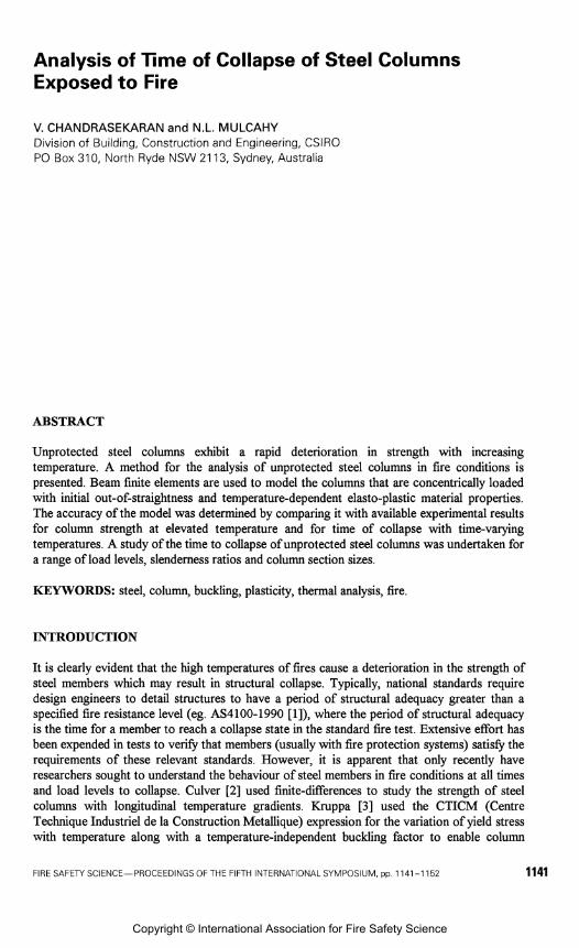
Analysis of Time of Collapse of Steel Columns Exposed to Fire
V. CHANDRASEKARAN and N.L. MULCAHY Division of Building, Construction and Engineering, CSlRO PO Box 31 0, North Ryde NSW 21 13, Sydney, Australia
ABSTRACT
Unprotected steel columns exhibit a rapid deterioration in strength with increasing temperature. A method for the analysis of unprotected steel columns in fire conditions is presented. Beam finite elements are used to model the columns that are concentrically loaded with initial out-of-straightness and temperature-dependent elasto-plastic material properties. The accuracy of the model was determined by comparing it with available experimental results for column strength at elevated temperature and for time of collapse with time-varying temperatures. A study of the time to collapse of unprotected steel columns was undertaken for a range of load levels, slenderness ratios and column section sizes.
KEYWORDS: steel, column, buckling, plasticity, thermal analysis, fire
INTRODUCTION
It is clearly evident that the high temperatures of fires cause a deterioration in the strength of steel members which may result in structural collapse. Typically, national standards require design engineers to detail structures to have a period of structural adequacy greater than a specified fire resistance level (eg. AS4100-1990 [I]), where the period of structural adequacy is the time for a member to reach a collapse state in the standard fire test. Extensive effort has been expended in tests to verify that members (usually with fire protection systems) satisfy the requirements of these relevant standards. However, it is apparent that only recently have researchers sought to understand the behaviour of steel members in fire conditions at all times and load levels to collapse. Culver [2] used finite-differences to study the strength of steel columns with longitudinal temperature gradients. Kruppa [3] used the CTICM (Centre Technique Industriel de la Construction Metallique) expression for the variation of yield stress with temperature along with a temperature-independent buckling factor to enable column
FIRE SAFETY SCIENCE-PROCEEDINGS OF THE FIFTH INTERNATIONAL SYMPOSIUM, pp 1141 -1 152 1141
Copyright © International Association for Fire Safety Science
strength to be calculated at elevated temperatures. Vandamme and Janss [4] and Janss and Mime [S] developed a similar procedure with ECCS (European Convention for Constructional Steelwork) expressions and compared the method with a large number of experimental results. Rubert and Schaumann [6] used finite element analysis results to develop a method for estimating column temperature at collapse. Olawale and Plank [7] and Burgess et al. [S] present a finite strip method for analysing the behaviour of pin-ended columns at elevated temperatures. Skowronski [9] derived expressions for estimating the fire resistance (collapse time) of steel columns. Poh and Bennetts [lo] describe a numerical method of analysing steel columns in fire conditions which allows the collapse time to be estimated.
A method which is applicable to the analysis of unprotected steel columns exposed to fire is presented. The column is modelled by prismatic beam-column finite elements with large deformations, material nonlinearity, initial deformations and partial end fixity included in the analysis. Either the collapse load of a steel column may be determined for a given steel temperature, or the time to collapse may be evaluated for a temperature history similar to that from a standard furnace test. This method is validated by comparing it with experimental results. As well, solutions for the time of collapse of unprotected steel columns are presented.
GOVERNING EQUATIONS
Two-dimensional beam-column finite elements are used to model the column. Element equations are formed in a local JT - 8 coordinate system and transformed to the global x - y system prior to assembly into the structure equations (Przemieniecki [ll]). The elements have linear interpolation of neutral axis F-displacements u, and cubic interpolation of 8- displacements uy . Section rotation is equal to the slope du, /& and rotations are assumed to
be small. Element nodal displacements ii consist of two displacements and a rotation at each end of the element. Przemieniecki [ l l ] gives expressions for the displacement distribution within the element and the appropriate derivatives.
Total strains are a linear combination of the strains that produce stress, the strains due to initial deformations and the thermal strains. Shear strains are assumed to be negligible and thus only the normal strains are included in the analysis. The total normal strain E, is determined from
du, dZuy - & =---
where 7 is measured from the neutral axis of the beam, E, is the neutral axis strain and K~ = d Z ~ y / & 2 is the curvature. Strain E, and curvature K, are taken to be generalised
strains E and are related to the local nodal displacements i i by
and incremental strains 6s and incremental displacements &i are related by
(Zienkiewicz [12]) . Arrays Bo and B, contain polynomial terms - B, is the same as the linear small displacement strain-displacement matrix and B, is a nonlinear large-displacement component which depends on the current displacements. Both total strains E, and strains due to initial deformations E,, are evaluated using the above expressions after substitution of the appropriate nodal displacements. The thermal strain is
where a is the coefficient of thermal expansion and AT is the temperature difference from the strain free state. Normal stress is
where E, is the secant modulus. The axial force N, and moment M, are taken to be generalised stresses and
where
and b is the width of the beam section which may vary over the section depth. The beam section consists of a number of component rectangles, with all integrals computed numerically.
Element local nodal displacements ii are related to structure nodal displacements u by
The equilibrium equations of the structure are
where
is the domain, K is a symmetric matrix similar to a secant stiffness matrix, K, is a diagonal matrix of nodal spring stiffnesses, P is the applied load vector, Po is the initial deformation load vector, u, is the initial deformation vector, PT is the thermal load vector, and PC is an additional correcting force. The integral over the domain volume implies integration over each element length and summation over all elements. Nodal spring stiffnesses are included to enable partial end fixity of columns to be modelled.
THERMO-ELASTIC-PLASTIC MATERIAL MODEL
The steel material model incorporates temperature-dependent material properties and has similar expressions to that of the general model of Snyder and Bathe [13]. The present model is suited to uniaxial stress and strain only, and does not include creep effects.
It is assumed that total strain E, can be expressed as the sum of elastic strains E,, plastic strains E ~ , strains due to initial deformations E,, and thermal strains E,,
The normal stress ox and yield finction F for a material with temperature-dependent elastic modulus E and yield stress Yare
where s, is the sign of the normal stress. The time rate of change of normal stress is
where the dot superscript denotes derivative with respect to time z. Assume that the plastic strain rate is defined by
where h is a positive scalar variable. For isotropic hardening the yield stress is a hnction of temperature T and the accumulated plastic strain
The time rate of change of 2, is then equal to h. During plastic straining, the stress- temperature state remains at yield so that
Multiplying the above expression by s,, substituting the expression for b,, and noting that ir, = AsX, then
Estimates for the values of plastic strain "E,, accumulated plastic strain %,, and normal stress '(7, at time z are
where Az is the time increment, the left superscript indicates the time at which a quantity occurs, and
Given the stress and strains, the secant modulus can be calculated as
EQUATION SOLUTION
The governing equations can be solved with constant temperature and incrementally applied loads, or with constant applied loads and temperature which varies with time. For the incremental applied load analysis the nonlinear equations are solved by an iterative scheme which incorporates a form of the constant arc length method (Crisfield [14]) but with a secant rather than tangent stiffness formulation. The constant arc length method applies a constraint to the structure displacements so that the norm of the change in displacements from step to step is constant. The load factor (ie. proportion of the total applied loads) is recalculated at each iteration to ensure that this constraint is satisfied. This enables the collapse load to be determined.
The thermal analysis with time-varying temperatures is assumed to be preceded by a static analysis whereby colunlr~ end loads are applied. The equilibrium equations are then solved with constant applied loads, and with temperatures that vary with time. As the load factor is constant and equals unity at all times after the initial application of loads, then the thermal analysis is not consistent with the mode of operation of the usual constant arc length method. Either constant time increments, or variable time increments with a constant arc length constraint, may be selected. The use of variable time increments and the arc length constraint enables the time of collapse of the column to be easily isolated. The constant arc length constraint is applied by assuming that the displacements vary linearly within a time increment and adjusting the length of the time increment at each iteration accordingly.
HEATFLOW ANALYSIS
In order to study the time of collapse of a steel column it is necessary to initially calculate the temperature history of the column. The heatflow analysis of unprotected steel columns assumes that as the thermal conductivity of steel is very large and therefore the temperatures at all points within the column at any time are the same. Bennetts et al. [15] give the governing equation of the resulting lumped heatflow analysis as
where T, is the steel temperature, z is time, a is the heat transfer coefficient, A is the surface area exposed to the fire, V is the volume of the column, Tf is the hrnace (or environmental)
temperature, p, is the steel density and C, is the specific heat capacity of steel. The heat
transfer coefficient a consists of a convection component a, (23 ~ m " " C-' , Kirby [16]) and a radiation component
where 0 is the Stefan-Boltzmann constant (5.67 x 1 0 - ~ w m " K ~ ) , E, is the resultant
emissivity (0.4, Kirby [16]), and the temperatures are in "C. The heat capacity of steel p, C, varies with temperature and is given by Lie [17] as
The I S 0 834 curve is adopted for the furnace temperature
where T, is the initial temperature (20°C), and z is the time in minutes. With the introduction of a difference expression for the derivative term in the governing equation the following equation can be solved iteratively for the steel temperature T, at each time z
where AT is the time increment, the k subscript indicates iteration number and the superscript indicates the time at which the term is evaluated.
RESULTS AND DISCUSSION
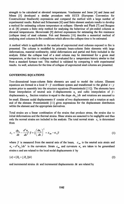
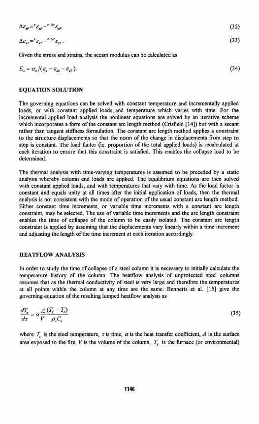
Comparisons were made with test results for columns at ambient and high temperatures in order to verify the accuracy of the method. Initial out-of-straightness was in the form of the column elastic buckled shape and of maximum magnitude consistent with the Australian Steel Structures Code AS4100-1990 [ l ] expression for the buckling strength of hot rolled universal sections. Stress-strain curves for steel as recommended by the draft Eurocode 4 [18] were adopted with an ambient temperature elastic modulus of E = 200 x 103MPa (see Fig.1 for 250 MPa yield stress steel). The influence of creep is implicitly included in the stress-strain curves in an approximate manner for heating rates similar to those under standard fire conditions. Initial ambient temperature was assumed to be 20°C. Expressions for the variation of the linear coefficient of thermal expansion were taken from Lie [17]. For each analysis, the column was divided into thirty beam finite elements. In the following, L is the overall column length, I is the effective length, and r is the radius of gyration.
Stia~n Slenderness Ratlo. l i r
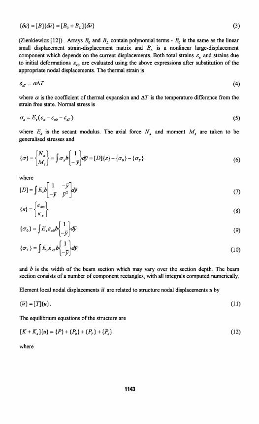
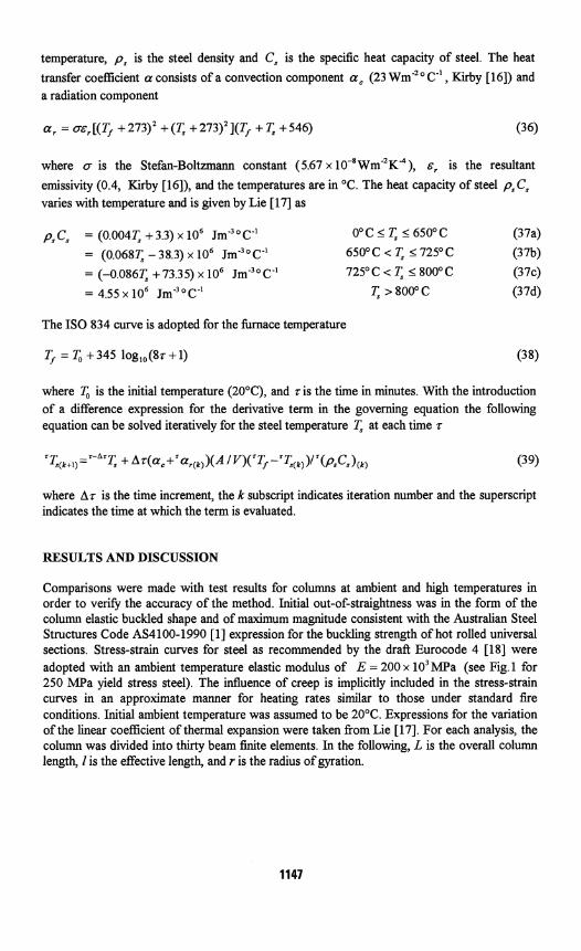
FIGURE 1. Steel stress-strain curves FIGURE: 2. Comparison of present model (1990 draft Eurocode 4 [18]). and ambient temperature tests [19].
Figure 2 shows a comparison with column tests of Strymowicz and Horsley [I91 which indicates that the present analysis marginally underestimates the strength of columns at ambient temperatures. The column considered was a 152mm x 152mm x 23 kg/m UC with average measured ambient temperature yield stress of 477 MPa.
Table 1 has a comparison with some fire test results conducted at the British Fire Research Station and reported by Proe et al. [20]. Load was applied to the columns and the temperature was increased until the average column temperature reached 500°C. The columns were still supporting the load at this temperature. Table 1 also presents buckling stresses which Proe et al. [20] calculated based on ECCS and CTICM reduction expressions for yield stress and modulus and the earlier Australian Steel Structures Code AS1250-1981 r211. The calculated
L 2
buckling stresses of the present analysis follow the general trend of the stresses calculated using the ECCS and CTICM expressions though for L l r = 56 the results for the present analysis are less than both the ECCS and CTICM results while for L 1 r = 37 and L I r = 40 the present analysis gives results intermediate between the ECCS and CTICM values. In all cases the calculated values are less than the experimentally applied stresses.
TABLE 1. Comparison with British Fire Research Station Tests
Notes: 1. Yield stress (minimum specified) = 250 MPa 2. Load removed from columns when temperature reached 500°C
Member Size
1 5 2 x l 5 2 x 2 3 U C 203 x 203 x 52 UC 31Ox31Ox198UC
Llr
56 40 37
Applied Stress ( m a )
130 140 140
Calculated Buckling Stress (MP a)
ECCS Expressions
106 113 114
CTICM Expressions
123 13 1 133
Present Analysis
103 121 125
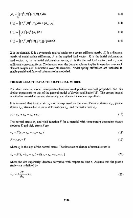
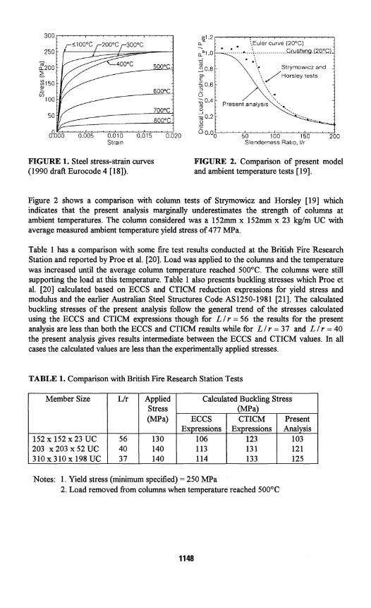
Figure 3 shows a plot of utilisation ratio (the ratio of column strength at a given temperature to the strength at ambient temperature) computed by the present analysis for an Australian 200UC52 column section which is pin-ended with slenderness ratio 1 l r = 90 buckling about the major axis. The ambient temperature yield stress of the steel is 250 MPa. For comparison, the results of the finite element analysis of Rubert and Schaumann [6], the finite strip
o analysis of Burgess et al. [S], and Temperature ("c) experimental results reported by Janss and
Minne [5] are plotted. Rubert and FIGURE 3. Comparison of computed and Schaumann [6] note that the utilisation ratio experimental utilisation ratio P, I P,,, . is a minimum in the middle range of column
- slenderness at A = 1 1 r ( a , / R ' E ) ~ a 1 ,
where a, is the yield stress, and E is the
elastic modulus. For steel with a yield stress of 250 MPa this corresponds to I l r = 90. The experimental points correspond to measured strength at a given temperature divided by ambient temperature strength estimated from the AS4100-1990 expression for hot rolled universal sections. The theoretical and experimental results of Fig.3 show similar variations of utilisation ratio with temperature. In order to determine the effects of end fixity, the same 200UC52 was examined for the cases: both ends pinned ( I = L), one end pinned and the other fixed (1 = 0.699L), and both ends fixed ( I = 0.5L). Initial deformations which are consistent with the AS4100 code expressions were used. Table 2 shows the ratio of critical load P, to ambient temperature crushing load P,,, at different temperatures for the three cases of end
fixity along with the pinned end results of Burgess et al. [8]. There are only marginal differences between the results for the different end fixities, indicating that the effective length concept is applicable at elevated temperatures as well as at ambient temperatures.
TABLE 2. Effect of End Fixity ( a y = 250 MPa , I / r = 90)
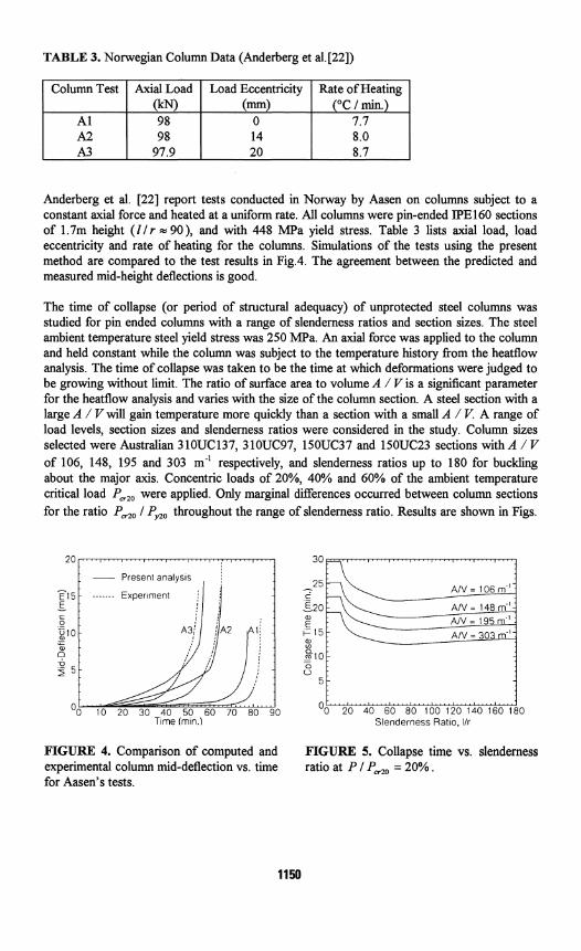
TABLE 3. Norwegian Column Data (Anderberg et a1.[22])
"C / rnin.
8.0 A3 97.9 20 8.7
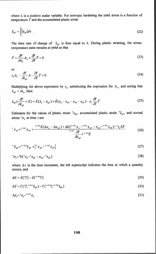
Anderberg et al. [22] report tests conducted in Norway by Aasen on columns subject to a constant axial force and heated at a uniform rate. All columns were pin-ended IPE160 sections of 1.7m height (Zlr w go), and with 448 MPa yield stress. Table 3 lists axial load, load eccentricity and rate of heating for the columns. Simulations of the tests using the present method are compared to the test results in Fig.4. The agreement between the predicted and measured mid-height deflections is good.
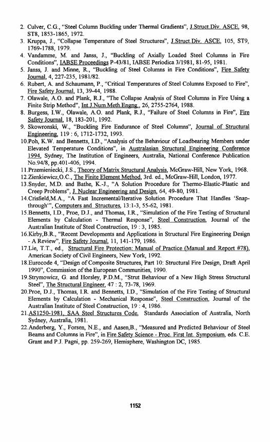
The time of collapse (or period of structural adequacy) of unprotected steel columns was studied for pin ended columns with a range of slenderness ratios and section sizes. The steel ambient temperature steel yield stress was 250 MPa. An axial force was applied to the column and held constant while the column was subject to the temperature history from the heatflow analysis. The time of collapse was taken to be the time at which deformations were judged to be growing without limit. The ratio of surface area to volume A / V is a significant parameter for the heatflow analysis and varies with the size of the column section. A steel section with a large A / V will gain temperature more quickly than a section with a small A / V. A range of load levels, section sizes and slenderness ratios were considered in the study. Column sizes selected were Australian 3 10UC137, 3 10UC97, 150UC37 and 150UC23 sections with A / V of 106, 148, 195 and 303 m-' respectively, and slenderness ratios up to 180 for buckling about the major axis. Concentric loads of 20%, 40% and 60% of the ambient temperature critical load P,,, were applied. Only marginal differences occurred between column sections for the ratio P,,, / P,,, throughout the range of slenderness ratio. Results are shown in Figs.
FIGURE 4. Comparison of computed and FIGURE 5. Collapse time vs. slenderness experimental column mid-deflection vs. time ratio at P / P,,, = 20%. for Aasen's tests.
, . . , . . . . # . . . . , , , , , Z . . . . , . . . .
A/V = 106 m."
A/V = 148 m" { AIV = 195 m ' : AIV = 303 m':
0 1 0 : - - 0 0 :
5 -
-
' 0 1 0 20 30 40 50 60 70 80 90 Oo" 2 'o" io" '60"s 'o ' i b o ' i + o ' i h o ' i bo ' i a o T~me 1m1n.i Slenderness Ratio. I r
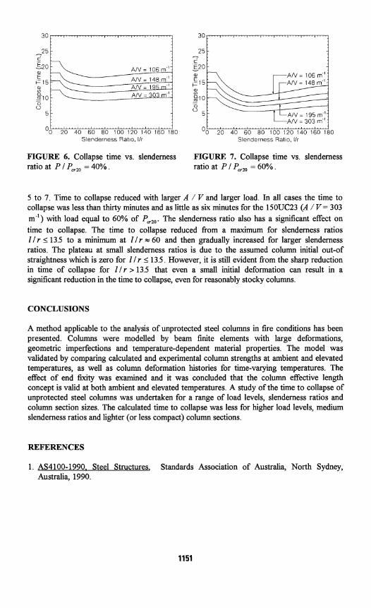
FIGURE 6. Collapse time vs. slenderness FIGURF, 7. Collapse time vs. slenderness ratio at P I P,,, = 40%. ratio at P 1 P,,, = 60% .
3 0 . . ~ . . , . . . ~ r ~ ~ ~ r ~ . - 7 - . ~ . 8 . - . . ~ 3 . . . r ~ ~ , ~ . 3 0 . . . . . . . 1 . , . . . . r , . m , z . , . . z . . , , .
5 to 7. Time to collapse reduced with larger A / V and larger load. In all cases the time to collapse was less than thirty minutes and as little as six minutes for the 150UC23 (A / V = 303 m-') with load equal to 60% of P,,, The slenderness ratio also has a significant effect on time to collapse. The time to collapse reduced from a maximum for slenderness ratios l / r 1 13.5 to a minimum at l 1 r 4 60 and then gradually increased for larger slenderness ratios. The plateau at small slenderness ratios is due to the assumed column initial out-of straightness which is zero for I 1 r 1 13.5. However, it is still evident from the sharp reduction in time of collapse for l l r > 13.5 that even a small initial deformation can result in a significant reduction in the time to collapse, even for reasonably stocky columns.
- 25
CONCLUSIONS
1
A method applicable to the analysis of unprotected steel columns in fire conditions has been presented. Columns were modelled by beam finite elements with large deformations, geometric imperfections and temperature-dependent material properties. The model was validated by comparing calculated and experimental column strengths at ambient and elevated temperatures, as well as column deformation histories for time-varying temperatures. The effect of end fixity was examined and it was concluded that the column effective length concept is valid at both ambient and elevated temperatures. A study of the time to collapse of unprotected steel columns was undertaken for a range of load levels, slenderness ratios and column section sizes. The calculated time to collapse was less for higher load levels, medium slenderness ratios and lighter (or less compact) column sections.
REFERENCES
- . 25
E A I V = 1 0 6 r n 1 _ - E20:
1. AS4100-1990. Steel Structures, Standards Association of Australia, North Sydney, Australia, 1990.
: :
- A / V = i 4 8 r n 1 ~
0 . 0 :
5 r
O o ' ' ' ;a" 20" s'a ' ' i d " i b o l'zo ' i 4 0 ' l ' k o '1'80 Slenderness R a t o , lir Slenderness Ratlo, / r
2. Culver, C.G., "Steel Column Buckling under Thermal Gradients", J.Struct.Div. ASCE, 98, ST8, 1853-1865, 1972.
3. Kruppa, J., "Collapse Temperature of Steel Structures", J.Struct.Div. ASCE, 105, ST9, 1769-1788, 1979.
4. Vandamme, M. and Janss, J., "Buckling of Axially Loaded Steel Columns in Fire Conditions", IABSE Proceedings P-4318 1, IABSE Periodica 311981, 8 1-95, 198 1.
5. Janss, J. and Minne, R., "Buckling of Steel Columns in Fire Conditions", Fire Safety Journal, 4, 227-235, 1981182.
6. Rubert, A. and Schaumann, P., "Critical Temperatures of Steel Columns Exposed to Fire", Fire Safetv Journal, 13, 39-44, 1988.
7. Olawale, A.O. and Plank, R.J., "The Collapse Analysis of Steel Columns in Fire Using a Finite Strip Method", Int.J.Num.Meth.Engnp., 26, 2755-2764, 1988.
8. Burgess, I.W., Olawale, A.O. and Plank, R.J., "Failure of Steel Columns in Fire", Safety Journal, 18, 183-201, 1992.
9. Skowronski, W., "Buckling Fire Endurance of Steel Columns", Journal of Structural Enrrineering, 119 : 6, 1712-1732, 1993.
lO.Poh, K.W. and Bennetts, I.D., "Analysis of the Behaviour of Loadbearing Members under Elevated Temperature Conditions", in Australasian Structural Engineering Conference 1994, Sydney, The Institution of Engineers, Australia, National Conference Publication No.9418, pp.401-406, 1994.
1 l.Przemieniecki, J.S., Theory of Matrix Structural Analvsis, McGraw-Hill, New York, 1968. 12.Zienkiewicz,O.C., The Finite Element Method, 3rd. ed., McGraw-Hill, London, 1977. 13.Snyder, M.D. and Bathe, K.-J., "A Solution Procedure for Thermo-Elastic-Plastic and
Creep Problems", J. Nuclear Engineering and Design, 64, 49-80, 198 1. 14.Crisfield,M.A., "A Fast IncrementallIterative Solution Procedure That Handles 'Snap-
through"', Comvuters and Structures, 13: 1-3, 55-62, 1981. 15,Bennetts, I.D., Proe, D.J., and Thomas, I.R., "Simulation of the Fire Testing of Structural
Elements by Calculation - Thermal Response", Steel Construction, Journal of the Australian Institute of Steel Construction, 19 : 3, 1985.
16.Kirby,B.R., "Recent Developments and Applications in Structural Fire Engineering Design - AReview", Fire Safetv Journal, 11, 141-179, 1986.
17.Lie, T.T., ed., Structural Fire Protection: Manual of Practice (Manual and Report #78), American Society of Civil Engineers, New York, 1992.
18.Eurocode 4, "Design of Composite Structures, Part 10: Structural Fire Design, Draft April 1990", Commission of the European Communities, 1990.
19.Strymowicz, G. and Horsley, P.D.M., "Strut Behaviour of a New High Stress Structural Steel", The Structural Engineer, 47 : 2, 73-78, 1969.
20.Proe, D.J., Thomas, I.R. and Bennetts, I.D., "Simulation of the Fire Testing of Structural Elements by Calculation - Mechanical Response", Steel Construction, Journal of the Australian Institute of Steel Construction, 19 : 4, 1986.
21 .AS 1250-1981, SAA Steel Structures Code, Standards Association of Australia, North Sydney, Australia, 1981.
22.Anderberg, Y., Forsen, N.E., and Aasen,B., "Measured and Predicted Behaviour of Steel Beams and Columns in Fire", in Fire Safetv Science - Proc. First Int. Symposium, eds. C.E. Grant and P.J. Pagni, pp. 259-269, Hemisphere, WashingtonDC, 1985.