Embed Size (px)
Citation preview
www.lasertools.co.uk
6605
www.lasertools.co.uk
Instructions
Sound Level Meter
Distributed by The Tool Connection Ltd
Kineton Road, Southam, Warwickshire CV47 0DR T +44 (0) 1926 815000 F +44 (0) 1926 815888 [email protected] www.toolconnection.co.uk
If this product fails through faulty materials or workmanship, contact our service department direct on: +44 (0) 1926 818186. Normal wear and tear are excluded as are consumable items and abuse.
Guarantee
The Laser 6605 is a high quality Sound Level Meter used for measurement of mechanical and environmental noise. It is a Class 2 Sound Level Meter designed to meet the requirements of IEC 61672-1. Typically, Class 2 Sound Level Meters are suitable for occupational noise measurements such as the UK Controls of Noise at Work Regulations or the OSHA Occupational Noise standards.
Thus it is ideal for:• Occupational and industrial hygiene noise evaluations.• Noise at Work surveys and Noise Exposure calculations.• Noise Ordinance Enforcement.• Machinery noise tests.• General noise measurements.
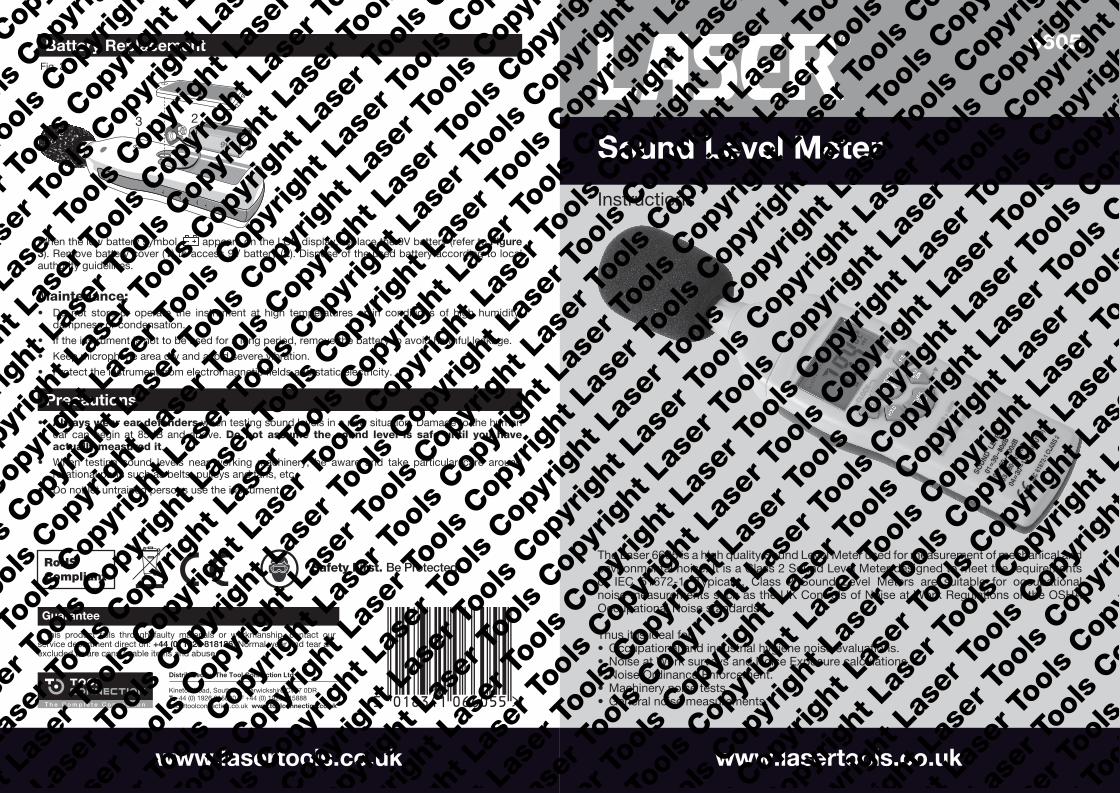
When the low battery symbol appears on the LCD display, replace the 9V battery (refer to Figure 3). Remove battery cover (1) to access 9V battery (2). Dispose of the used battery according to local authority guidelines.
Maintenance:• Do not store or operate the instrument at high temperatures or in conditions of high humidity,
dampness or condensation.
• If the instrument is not to be used for a long period, remove the battery to avoid harmful leakage.
• Keep microphone area dry and avoid severe vibration.
• Protect the instrument from electromagnetic fields and static electricity.
Battery Replacement
Precautions• Always wear ear defenders when testing sound levels in a new situation. Damage to the human
ear can begin at 85dB and above. Do not assume the sound level is safe until you haveactually measured it.
• When testing sound levels near working machinery, be aware and take particular care aroundrotational parts such as belts, pulleys and fans, etc.
• Do not let untrained persons use the instrument.
Fig. 2
MAINDISPLAY
RANGEINDICATOR
9V
Fig. 3
1
23

2 3
Controls
LCD Display
A Wind shieldB LCD displayC ON/OFF & BacklightD Frequency weighting buttonE HOLD buttonF Level range & RecordG Fast/Slow time weightingH Max/Min hold button
Note: In even mild windy conditions it is essential that the wind shield (A) is used to reduce the effects of wind and air movement across the microphone and thus avoid picking up background noise. The wind shield also protects the sensitive microphone from damage and keeps the microphone capsule clean.
1. Refer to Figure 1: Turn the instrument ON by pressing the ON/OFF button (C).
2. Press the LEVEL/REC button (F) to cycle through to the best level (of 4) for the noise measurement task in hand. Watch for the OVER and UNDER indicators at the top of the display; select a level where these indicators are off.
3. Press the A/C button (D) to choose the required filter dBA or dBC; each filter has a different sensitivity to various frequencies. The dBA sound level meter applies to the mid-range frequencies as opposed to the dBC sound level meter that measures low and high frequencies. For example, when transmitted sound has bass issues or problems, the C filter is typically used (entertainment venues, etc), or for high pitched sounds from machinery.
4. The F/S button (G) selects either FAST sampling for instant sound or SLOW sampling for an average sound level.
5. The MAX/MIN button (H) is used when you need to monitor the maximum sound level, or minimum sound level, at the time of measuring.
6. You can measure sound levels by holding the instrument in your hand, or mounting on a tripod, ideally 1-1.5 metres from the sound source. Refer to (3) in Figure 3 for position of tripod mount.
6605
RECO
RD:
HOLD
+ L
EVEL
CLO
CK
EX
IT
READ
: LE
VEL
+
SOUN
D LE
VEL:
A/C
ON
/OFF
HOLD
MAX
MINF/
S
ERAS
E M
EMOR
Y: H
OLD
+
01=
30 ~
80dB
02=
50 ~
100d
B03
=80
~13
0dB
04=
30 ~
130d
B (A
UTO)
IEC
6167
2-1
CLAS
S 2
LEVE
LRE
C
A
B
C D E
G H
F
Fig. 1
Fig. 2
MAINDISPLAY
RANGEINDICATOR
Symbol FunctionMN MIN – Minimum sound level captureMX MAX – Maximum sound level captureF FAST sampling rateREC Data has been recordedS SLOW sampling rate Low batteryHOLD Data hold functiondBA A-weighting (response to human hearing)dBC C-weighting (response to machine monitoring)OVER Over upper limit of rangeUNDER Under lower limit of range
Fig. 2
MAINDISPLAY
RANGEINDICATOR
Operation
• ON/OFF and backlight button (C): Press once to turn on the instrument; press again to turn on backlight; press again to switch off backlight. To turn instrument OFF, press and hold ON/OFF and backlight button; the display will count down P--3, P--2, P--1. When screen goes blank, release the button.
• Frequency weighting button (D): (Refer to point 3 in Operation section above).
• HOLD button (E): Data HOLD: Press button once to freeze the reading on the display; press again to return to live monitoring. Data ZERO: Instrument switched OFF: First press and hold the HOLD button then also press the ON/OFF button. Keep both buttons held down until CLA is displayed; this indicates that all readings stored in the memory have been erased.
• LEVEL RANGE/RECORD button (F):
1. Range select: the range level is represented on the display by the two small digits on the right-hand side (refer to “Range Indicator” on Figure 2). Cycle through the 4 available levels by pressing the button: 01 (low level): 30-80dB; 02 (medium level): 50-100dB; 03 (high level): 80-130dB; 04 (AUTO): 30-130dB.
2. REC Record Function: To record readings, first press the HOLD button (E) to freeze the display; then press the LEVEL/REC button (F) to place the reading into the memory. REC will appear on the display to indicate that the reading has been saved. Press the HOLD button again to return to live monitoring.
3. Data Reading Function: To read the data that you have recorded, first switch off the instrument; now hold down the LEVEL/REC button and press the ON/OFF button once. When dAtA is displayed, release the LEVEL/REC button and the first stored reading will be displayed. Up to 50 readings can be stored. Cycle through these readings by repeatedly pressing the LEVEL/REC button. For ease of reference, each reading is numbered 1 through to 50 as indicated by the two small digits on the right hand side of the display (refer to “Range Indicator” on Figure 2). Each reading has an automatically recorded date and time; press the HOLD button once to see the date; press the HOLD button again to see the time. A third press of the HOLD button returns the display to the recorded reading. (See section below on how to set the date and time on the instrument).
• MAX/MIN button (H): (Maximum and Minimum Hold): Select the required mode by pressing the MAX/MIN button; MX or MN will indicate mode. With MX mode, the maximum sound level will be captured and held by the instrument until a higher sound level is captured. In MN mode, the minimum sound level will be captured and held until a lower sound level is captured.
• Setting the Time & Date: To set, begin with the instrument switched OFF. To enter the setup mode, hold down the A/C button (D) a press the ON/OFF button (C) until SEt is displayed; release both buttons. The currently set date will be displayed in the format day/month/year; this screen cannot be edited. Press the A/C button again and the currently set time is displayed in the format hours/minutes/seconds; this screen cannot be edited.
1. To edit minutes: press the A/C button again to enter the edit minutes mode; use the LEVEL/REC button to advance the number; use the MAX/MIN button to decrease the number.
2. To edit hours: press the A/C button again to enter the edit hours mode; use the LEVEL/REC button to advance the number; use the MAX/MIN button to decrease the number.
3. To edit date: press the A/C button again to enter the edit date mode; use the LEVEL/REC button to advance the number; use the MAX/MIN button to decrease the number.
4. To edit month: press the A/C button again to enter the edit month mode; use the LEVEL/REC button to advance the number; use the MAX/MIN button to decrease the number.
5. To edit year: press the A/C button again to enter the edit year mode; use the LEVEL/REC button to advance the number; use the MAX/MIN button to decrease the number.
6. To exit setup mode and save your setting, press the HOLD button once.
7. Note: if you continue to press the A/C button in edit mode, the initialisation/reset screen is displayed; if your press the A/C button again your previous settings will be lost and the display reverts to the original factory settings.
Operation