Embed Size (px)
Citation preview
Doc. no.VP3145-OMM0002-B
PRODUCT NAME
3 Port Solenoid Valve
MODEL / Series / Product Number
VP31∗5 Series
Contents
Safety Instructions --------------------------------------------------------------------------------- 2, 3 Design/Selection ----------------------------------------------------------------------------------- 4, 5
Mounting --------------------------------------------------------------------------------------------- 5
Piping ------------------------------------------------------------------------------------------------- 5, 6
Wiring ------------------------------------------------------------------------------------------------- 6
Lubrication ------------------------------------------------------------------------------------------- 6
Air Supply -------------------------------------------------------------------------------------------- 6
Operating Environment --------------------------------------------------------------------------- 7
Maintenance ---------------------------------------------------------------------------------------- 7
Specific Product Precautions -------------------------------------------------------------------- 8~11
Troubleshooting ------------------------------------------------------------------------------------ 12, 13
- 1 - No.VP3145-OMM0002-B
Safety Instructions These safety instructions are intended to prevent hazardous situations and/or equipment damage. These instructions indicate the level of potential hazard with the labels of “Caution,” “Warning” or “Danger.” They are all important notes for safety and must be followed in addition to International Standards (ISO/IEC)*1) , and other safety regulations. *1) ISO 4414: Pneumatic fluid power -- General rules relating to systems. ISO 4413: Hydraulic fluid power -- General rules relating to systems. IEC 60204-1: Safety of machinery -- Electrical equipment of machines .(Part 1: General requirements) ISO 10218: Manipulating industrial robots -Safety. etc.
Caution Caution indicates a hazard with a low level of risk which, if not avoided, could result in minor or moderate injury.
Warning Warning indicates a hazard with a medium level of risk which, if not avoided, could result in death or serious injury.
Danger Danger indicates a hazard with a high level of risk which, if not avoided, will result in death or serious injury.
Warning 1. The compatibility of the product is the responsibility of the person who designs the equipment or
decides its specifications. Since the product specified here is used under various operating conditions, its compatibility with specific equipment must be decided by the person who designs the equipment or decides its specifications based on necessary analysis and test results. The expected performance and safety assurance of the equipment will be the responsibility of the person who has determined its compatibility with the product. This person should also continuously review all specifications of the product referring to its latest catalog information, with a view to giving due consideration to any possibility of equipment failure when configuring the equipment.
2. Only personnel with appropriate training should operate machinery and equipment. The product specified here may become unsafe if handled incorrectly. The assembly, operation and maintenance of machines or equipment including our products must be performed by an operator who is appropriately trained and experienced.
3. Do not service or attempt to remove product and machinery/equipment until safety is confirmed. 1.The inspection and maintenance of machinery/equipment should only be performed after measures to
prevent falling or runaway of the driven objects have been confirmed. 2.When the product is to be removed, confirm that the safety measures as mentioned above are implemented and the power from any appropriate source is cut, and read and understand the specific product precautions of all relevant products carefully. 3. Before machinery/equipment is restarted, take measures to prevent unexpected operation and malfunction.
4. Contact SMC beforehand and take special consideration of safety measures if the product is to be used in any of the following conditions. 1. Conditions and environments outside of the given specifications, or use outdoors or in a place exposed to direct sunlight. 2. Installation on equipment in conjunction with atomic energy, railways, air navigation, space, shipping,
vehicles, military, medical treatment, combustion and recreation, or equipment in contact with food and beverages, emergency stop circuits, clutch and brake circuits in press applications, safety equipment or other applications unsuitable for the standard specifications described in the product catalog.
3. An application which could have negative effects on people, property, or animals requiring special safety analysis.
4.Use in an interlock circuit, which requires the provision of double interlock for possible failure by using a mechanical protective function, and periodical checks to confirm proper operation.
- 2 - No.VP3145-OMM0002-B
Safety Instructions
Caution 1. The product is provided for use in manufacturing industries.
The product herein described is basically provided for peaceful use in manufacturing industries. If considering using the product in other industries, consult SMC beforehand and exchange specifications or a contract if necessary.
If anything is unclear, contact your nearest sales branch.
Limited warranty and Disclaimer/Compliance Requirements The product used is subject to the following “Limited warranty and Disclaimer” and “Compliance Requirements”. Read and accept them before using the product.
Limited warranty and Disclaimer 1.The warranty period of the product is 1 year in service or 1.5 years after the product is
delivered,whichever is first.∗2) Also, the product may have specified durability, running distance or replacement parts. Please consult your nearest sales branch.
2. For any failure or damage reported within the warranty period which is clearly our responsibility, a replacement product or necessary parts will be provided. This limited warranty applies only to our product independently, and not to any other damage
incurred due to the failure of the product. 3. Prior to using SMC products, please read and understand the warranty terms and disclaimers
noted in the specified catalog for the particular products. ∗2) Vacuum pads are excluded from this 1 year warranty. A vacuum pad is a consumable part, so it is warranted for a year after it is delivered.
Also, even within the warranty period, the wear of a product due to the use of the vacuum pad or failure due to the deterioration of rubber material are not covered by the limited
warranty.
Compliance Requirements 1. The use of SMC products with production equipment for the manufacture of weapons of mass
destruction(WMD) or any other weapon is strictly prohibited. 2. The exports of SMC products or technology from one country to another are governed by the
relevant security laws and regulation of the countries involved in the transaction. Prior to the shipment of a SMC product to another country, assure that all local rules governing that export are known and followed.
Caution SMC products are not intended for use as instruments for legal metrology. Measurement instruments that SMC manufactures or sells have not been qualified by type approval tests relevant to the metrology (measurement) laws of each country. Therefore, SMC products cannot be used for business or certification ordained by the metrology (measurement) laws of each country.
- 3 - No.VP3145-OMM0002-B
VP31∗5 Series 3 Port Solenoid Valve Precautions 1 Be sure to read this before handling products.
Design/Selection 1. Confirm the specifications.
This product is designed only for use in compressed air systems (including vacuum). Do not operate at pressures, temperatures, etc., beyond the range of specifications, as this can cause damage or malfunction. (Refer to the catalog) Please contact SMC when using a fluid other than compressed air (including vacuum). We do not guarantee against any damage if the product is used outside of the specification range.
2. Actuator drive When an actuator, such as a cylinder, is to be driven using a valve, take appropriate measures (such as the installation of a cover or the restricting of access to the product) to prevent potential danger caused by actuator operation.
3. Holding pressure (including vacuum) Since valves are subject to air leakage, they cannot be used for applications such as holding pressure (including vacuum) in a pressure vessel.
4. Not suitable for use as an emergency shutoff valve, etc. The valves presented in this catalog are not designed for safety applications (e.g. emergency shutoff valve). If the valves are used in such applications, additional safety measures should be adopted.
5. Release of residual pressure For maintenance and inspection purposes install a system for releasing residual pressure.
6. Operation in a vacuum condition When a valve is used for switching a vacuum, take measures to install a suction filter or similar to prevent external dust or other foreign matter from entering inside the valve. In addition, at the time of vacuum adsorption, be sure to supply a constant supply of vacuum. Failure to do so may result in foreign matter sticking to the adsorption pad or air leakage, causing the workpiece to drop.
7. Regarding vacuum switch valves and vacuum release valves If a non-vacuum valve is installed in the middle of a piping system that contains a vacuum, the vacuum condition will not be maintained. Use a valve designed for use under vacuum conditions.
8. Ventilation Provide ventilation when using a valve in a confined area, such as in a closed control panel. For example, install a ventilation opening, etc., in order to prevent pressure from increasing inside of the confined area and to release the heat generated by the valve.
9. Extended periods of continuous energization If a valve will be continuously energized for an extended period of time, the temperature of the valve will increase due to the heat generated by the coil assembly. This will likely adversely affect the performance of the valve and any nearby peripheral equipment.
10. Do not disassemble the product or make any modifications, including additional machining. Doing so may cause human injury and/or an accident. When the product is disassembled for maintenance, refer to “Overhaul / Cleaning / Addition of grease (VP31*5V series: Vacuum Specification)”.
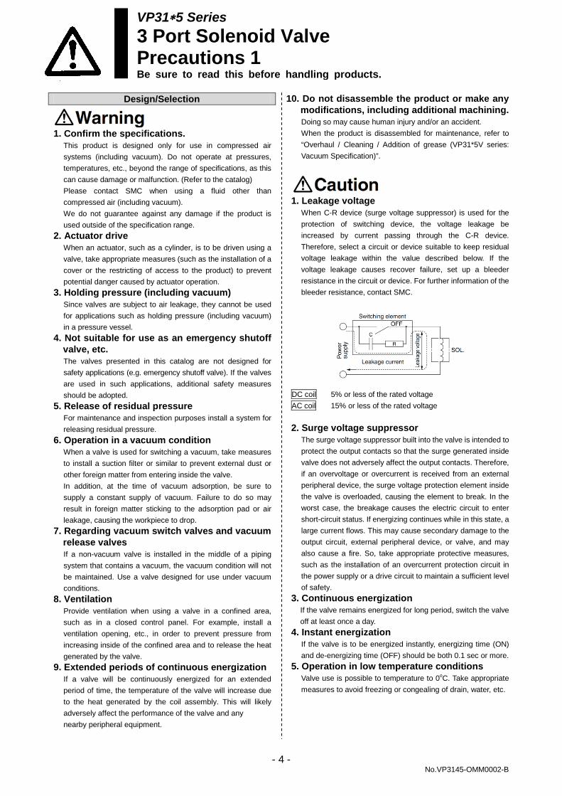
1. Leakage voltage
When C-R device (surge voltage suppressor) is used for the protection of switching device, the voltage leakage be increased by current passing through the C-R device. Therefore, select a circuit or device suitable to keep residual voltage leakage within the value described below. If the voltage leakage causes recover failure, set up a bleeder resistance in the circuit or device. For further information of the bleeder resistance, contact SMC.
DC coil 5% or less of the rated voltage AC coil 15% or less of the rated voltage 2. Surge voltage suppressor
The surge voltage suppressor built into the valve is intended to protect the output contacts so that the surge generated inside valve does not adversely affect the output contacts. Therefore, if an overvoltage or overcurrent is received from an external peripheral device, the surge voltage protection element inside the valve is overloaded, causing the element to break. In the worst case, the breakage causes the electric circuit to enter short-circuit status. If energizing continues while in this state, a large current flows. This may cause secondary damage to the output circuit, external peripheral device, or valve, and may also cause a fire. So, take appropriate protective measures, such as the installation of an overcurrent protection circuit in the power supply or a drive circuit to maintain a sufficient level of safety.
3. Continuous energization If the valve remains energized for long period, switch the valve off at least once a day.
4. Instant energization If the valve is to be energized instantly, energizing time (ON) and de-energizing time (OFF) should be both 0.1 sec or more.
5. Operation in low temperature conditions Valve use is possible to temperature to 0oC. Take appropriate measures to avoid freezing or congealing of drain, water, etc.
- 4 - No.VP3145-OMM0002-B
VP31∗5 Series 3 Port Solenoid Valve Precautions 2 Be sure to read this before handling products.
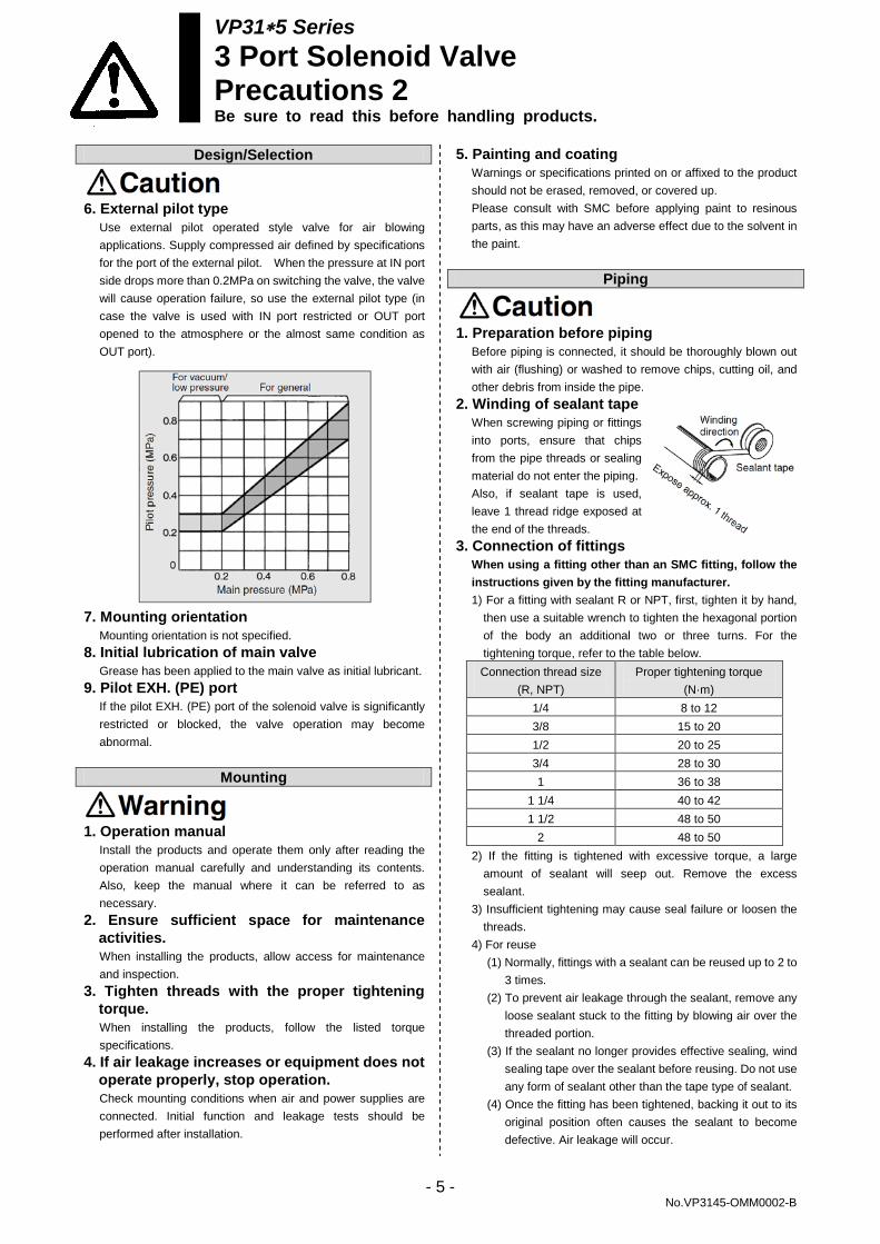
Design/Selection 6. External pilot type
Use external pilot operated style valve for air blowing applications. Supply compressed air defined by specifications for the port of the external pilot. When the pressure at IN port side drops more than 0.2MPa on switching the valve, the valve will cause operation failure, so use the external pilot type (in case the valve is used with IN port restricted or OUT port opened to the atmosphere or the almost same condition as OUT port).
7. Mounting orientation
Mounting orientation is not specified. 8. Initial lubrication of main valve
Grease has been applied to the main valve as initial lubricant. 9. Pilot EXH. (PE) port
If the pilot EXH. (PE) port of the solenoid valve is significantly restricted or blocked, the valve operation may become abnormal.
Mounting
1. Operation manual
Install the products and operate them only after reading the operation manual carefully and understanding its contents. Also, keep the manual where it can be referred to as necessary.
2. Ensure sufficient space for maintenance activities. When installing the products, allow access for maintenance and inspection.
3. Tighten threads with the proper tightening torque. When installing the products, follow the listed torque specifications.
4. If air leakage increases or equipment does not operate properly, stop operation. Check mounting conditions when air and power supplies are connected. Initial function and leakage tests should be performed after installation.
5. Painting and coating Warnings or specifications printed on or affixed to the product should not be erased, removed, or covered up. Please consult with SMC before applying paint to resinous parts, as this may have an adverse effect due to the solvent in the paint.
Piping
1. Preparation before piping
Before piping is connected, it should be thoroughly blown out with air (flushing) or washed to remove chips, cutting oil, and other debris from inside the pipe.
2. Winding of sealant tape When screwing piping or fittings into ports, ensure that chips from the pipe threads or sealing material do not enter the piping. Also, if sealant tape is used, leave 1 thread ridge exposed at the end of the threads.
3. Connection of fittings When using a fitting other than an SMC fitting, follow the instructions given by the fitting manufacturer. 1) For a fitting with sealant R or NPT, first, tighten it by hand,
then use a suitable wrench to tighten the hexagonal portion of the body an additional two or three turns. For the tightening torque, refer to the table below. Connection thread size
(R, NPT) Proper tightening torque
(N·m) 1/4 8 to 12 3/8 15 to 20 1/2 20 to 25 3/4 28 to 30 1 36 to 38
1 1/4 40 to 42 1 1/2 48 to 50
2 48 to 50 2) If the fitting is tightened with excessive torque, a large
amount of sealant will seep out. Remove the excess sealant.
3) Insufficient tightening may cause seal failure or loosen the threads.
4) For reuse (1) Normally, fittings with a sealant can be reused up to 2 to
3 times. (2) To prevent air leakage through the sealant, remove any
loose sealant stuck to the fitting by blowing air over the threaded portion.
(3) If the sealant no longer provides effective sealing, wind sealing tape over the sealant before reusing. Do not use any form of sealant other than the tape type of sealant.
(4) Once the fitting has been tightened, backing it out to its original position often causes the sealant to become defective. Air leakage will occur.
- 5 - No.VP3145-OMM0002-B
VP31∗5 Series 3 Port Solenoid Valve Precautions 3 Be sure to read this before handling products.
Piping 4. Uni thread fittings
1) First, tighten the threaded portion by hand, then use a suitable wrench to tighten the hexagonal portion of the body further at wrench tightening angle shown below. For the reference value for the tightening torque, refer to the table below.
Connection Female Thread: Rc, NPT, NPTF
Uni thread size
Wrench tightening angle
after tightened by hand
(deg)
Tightening torque
(N·m)
1/4 30 to 60 8 to 12 3/8 15 to 45 14 to 16 1/2 15 to 30 20 to 22
Connection Female Thread: G
Uni thread size
Wrench tightening angle
after tightened by hand
(deg)
Tightening torque
(N·m)
1/4 15 to 30 4 to 5 3/8 15 to 30 8 to 9 1/2 15 to 30 14 to 15
2) The gasket can be reused up to 6 to 10 times. It can be
replaced easily when it has sustained damage. A broken gasket can be removed by holding it and then turning it in the same direction as loosening the thread. If the gasket is difficult to remove, cut it with nippers, etc. In such a case, use caution not to scratch the seat face because the seat face of the fitting’s 45° gasket is the sealing face.
5. Piping to products When connecting piping to the product, refer to the catalog to avoid mistakes regarding the supply port, etc.
Wiring
1. The solenoid valve is an electrical product.
For safety, install an appropriate fuse and circuit breaker before use.
1. Polarity
No +/- polarity for this solenoid valve. 2. Applied voltage
When electric power is connected to a solenoid valve, be careful to apply the proper voltage. Improper voltage may cause malfunction or coil damage.
3. Check the connections. Check if the connections are correct after completing all wiring.
4. External force applied to the lead wire If an excessive force is applied to the lead wire, this may cause faulty wiring. Take appropriate measures so that a force of 30 N or more is not applied to the lead wire.
Lubrication This is a valve which requires lubrication. Be sure to lubricate it for operation. It may cause problems such as damage and malfunction of the valve if it is not lubricated. A valve of vacuum specification needs overhaul for cleaning and addition of grease because it cannot be lubricated without it. (Refer to page 11.) 1) If a lubricant is used in the system, use class 1 turbine oil (no
additive), ISO VG32. 2) Please contact SMC regarding class 2 turbine oil (with
additives), ISO VG32. 1. Lubrication amount
If too much oil is applied, it may accumulate in the product, causing malfunction or response delay. So, do not apply a large amount of oil.
Air Supply
1. Use clean air
Do not use compressed air that contains chemicals, synthetic oils that include organic solvents, salt, corrosive gases, etc., as it can cause damage or malfunction.
1. Install an air filter.
Install an air filter upstream near the valve. Select an air filter with a filtration size of 5 μm or smaller.
2. Take measures to ensure air quality, such as by installing an aftercooler, air dryer, or water separator. Compressed air that contains a large amount of drainage can cause the malfunction of pneumatic equipment, such as valves. Therefore, take appropriate measures to ensure air quality, such as by providing an aftercooler, air dryer, or water separator.
3. If an excessive amount of carbon powder is present, install a mist separator on the upstream side of the valve. If excessive carbon dust is generated by the compressor, it may adhere to the inside of a valve and cause it to malfunction.
For compressed air quality, refer to the SMC Best Pneumatics catalog No. 6.
- 6 - No.VP3145-OMM0002-B
VP31∗5 Series 3 Port Solenoid Valve Precautions 4 Be sure to read this before handling products.
Operating Environment 1. Do not use in an atmosphere containing
corrosive gases, chemicals, sea water, water, water steam, or where there is direct contact with any of these.
2. Do not use in an environment where flammable gas or explosive gas exists. Usage may cause a fire or explosion. The products do not have an explosion proof construction.
3. Do not use in a place subject to heavy vibration and/or shock.
4. The valve should not be exposed to prolonged sunlight. Use a protective cover. Note that the valve is not for outdoor use.
5. Remove any sources of excessive heat. 6. If it is used in an environment where there is
possible contact with a waterdrop, oil, weld spatter, etc., exercise preventive measures.
7. When the solenoid valve is mounted in a control panel or it’s energized for a long period of time, make sure the ambient temperature is within the specifications of the valve.
1. Temperature of ambient environment
Use the valve within the range of the ambient temperature specification of each valve. In addition, pay attention when using the valve in environments where the temperature changes drastically.
2. Humidity of ambient environment ● When using the valve in environments with low humidity,
take measures to prevent static. ● If the humidity rises, take measures to prevent the adhesion
of water droplets on the valve.
Maintenance 1. Perform maintenance and inspection
according to the procedures indicated in the operation manual. If handled improperly, human injury and/or malfunction or damage of machinery and equipment may occur.
2. Removal of equipment, and supply/exhaust of compressed air Before components are removed, first confirm that measures are in place to prevent workpieces from dropping, run-away equipment, etc. Then, cut off the supply air and electric power, and exhaust all air pressure from the system using the residual pressure release function. When the equipment is operated after remounting or replacement, first confirm that measures are in place to prevent the lurching of actuators, etc. Then, confirm that the equipment is operating normally.
3. Low-frequency operation Valves should be operated at least once every 30 days to prevent malfunction. (Use caution regarding the air supply.)
4. Manual override When a manual override is operated, connected equipment will be actuated. Operate only after safety is confirmed.
5. If the volume of air leakage increases or the valve does not operate normally, do not use the valve. Perform periodic maintenance on the valve to confirm the operating condition and check for any air leakage.
1. Drain flushing
Remove drainage from the air filters regularly.
- 7 - No.VP3145-OMM0002-B
VP31∗5 Series
Specific Product Precautions (1) Be sure to read this before handling the products.
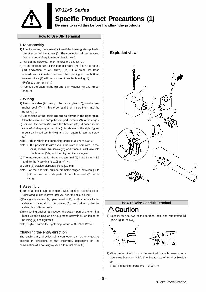
How to Use DIN Terminal 1. Disassembly 1) After loosening the screw (1), then if the housing (4) is pulled in
the direction of the screw (1), the connector will be removed from the body of equipment (solenoid, etc.).
2) Pull out the screw (1), then remove the gasket (2). 3) On the bottom part of the terminal block (3), there’s a cut-off
part (indication of an arrow) (3a). If a small flat head screwdriver is inserted between the opening in the bottom, terminal block (3) will be removed from the housing (4). (Refer to graph at right.)
4) Remove the cable gland (5) and plain washer (6) and rubber seal (7).
2. Wiring 1) Pass the cable (8) through the cable gland (5), washer (6),
rubber seal (7), in this order and then insert them into the housing (4).
2) Dimensions of the cable (8) are as shown in the right figure. Skin the cable and crimp the crimped terminal (9) to the edges.
3) Remove the screw (3f) from the bracket (3e). (Loosen in the case of Y-shape type terminal.) As shown in the right figure, mount a crimped terminal (9), and then again tighten the screw (3f).
Note) Tighten within the tightening torque of 0.5 N·m ±15%. Note: a) It is possible to wire even in the state of bare wire. In that
case, loosen the screw (3f) and place a lead wire into the bracket (3d), and then tighten it once again.
b) The maximum size for the round terminal (9) is 1.25 mm2 - 3.5 and for the Y terminal is 1.25 mm2 - 4.
c) Cable (8) outside diameter: φ6 to φ12 mm Note) For the one with outside diameter ranged between φ9 to
φ12 remove the inside parts of the rubber seal (7) before using.
3. Assembly 1) Terminal block (3) connected with housing (4) should be
reinstated. (Push it down until you hear the click sound.) 2) Putting rubber seal (7), plain washer (6), in this order into the
cable introducing slit on the housing (4), then further tighten the cable gland (5) securely.
3) By inserting gasket (2) between the bottom part of the terminal block (3) and a plug on an equipment, screw in (1) on top of the housing (4) and tighten it.
Note) Tighten within the tightening torque of 0.5 N·m ±20%. Changing the entry direction The cable entry direction of a connector can be changed as desired (4 directions at 90° intervals), depending on the combination of a housing (4) and a terminal block (3).
How to Wire Conduit Terminal 1) Loosen four screws at the terminal box, and removethe lid.
(See figure below.)
2) Wire the terminal block in the terminal box with power source
side. (See figure on right). The thread size of terminal block is M4. Note) Tightening torque 0.6+/- 0.06N・m
Exploded view
- 8 - No.VP3145-OMM0002-B
VP31∗5 Series
Specific Product Precautions (2) Be sure to read this before handling the products.
N.C./ N.O. Conversion To convert valve operation from N.C. to N.O. or N.O. to N.C., remove the pilot valve, move the function plate along the gasket, both top and bottom until the mark ▲ meets N.C. (N.O.) Please note however, that the N.O. valve functions properly only when the appropriate pressure is applied to the valve.
N.C./ N.O. conversion When converting from N.C. to N.O. and vice versa, note that the equipment to be connected will act reversely.
Light/Surge Voltage Suppressor
Other Precautions 1. Pressure balance among each port
This solenoid valve is pressure-unbalanced type. Operate it within this pressure range: IN ≥ OUT ≥ EXH. If not operated in the range, the valve will malfunction.
2. Use as 2 port valve 1. Plug EXH port in case of pressure-in and plug IN port in
case of vacuum use. 2. This valve has slight air leakage and can not be used for
such purposes as holding air pressure (including vacuum) in the pressure container.
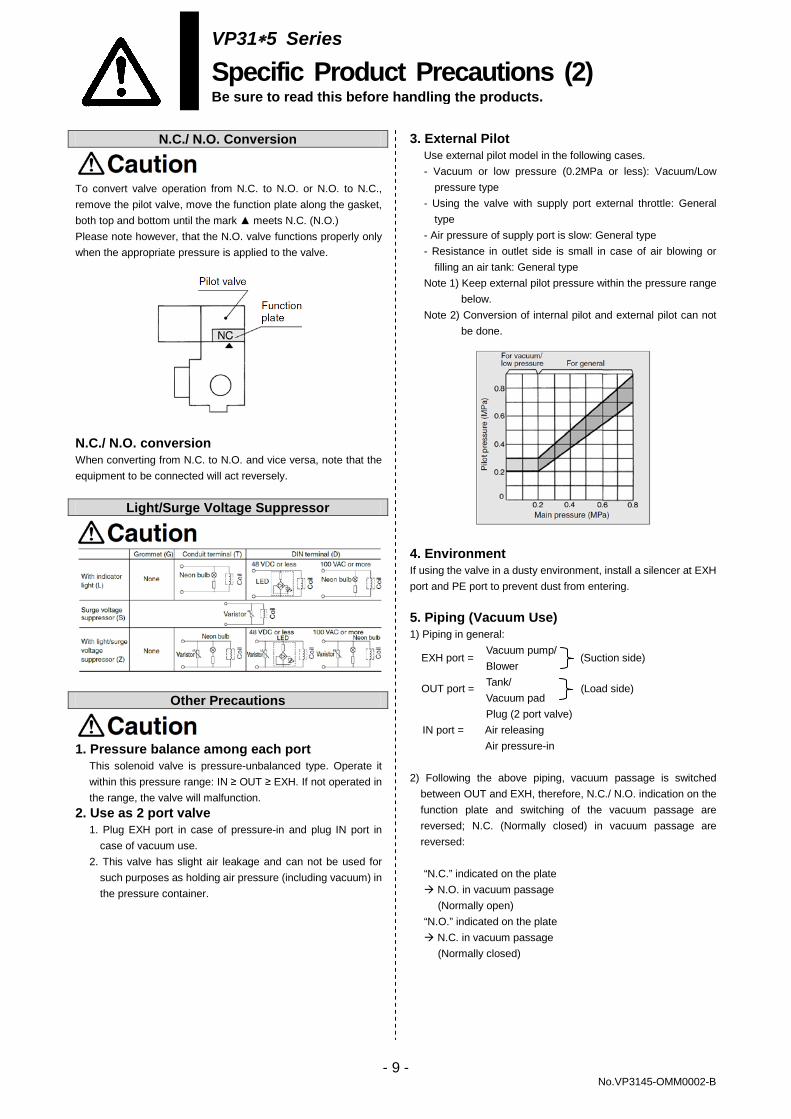
3. External Pilot Use external pilot model in the following cases. - Vacuum or low pressure (0.2MPa or less): Vacuum/Low
pressure type - Using the valve with supply port external throttle: General
type - Air pressure of supply port is slow: General type - Resistance in outlet side is small in case of air blowing or
filling an air tank: General type Note 1) Keep external pilot pressure within the pressure range
below. Note 2) Conversion of internal pilot and external pilot can not
be done.
4. Environment If using the valve in a dusty environment, install a silencer at EXH port and PE port to prevent dust from entering. 5. Piping (Vacuum Use) 1) Piping in general:
Vacuum pump/ Blower Tank/ Vacuum pad Plug (2 port valve)
IN port = Air releasing Air pressure-in
2) Following the above piping, vacuum passage is switched
between OUT and EXH, therefore, N.C./ N.O. indication on the function plate and switching of the vacuum passage are reversed; N.C. (Normally closed) in vacuum passage are reversed:
“N.C.” indicated on the plate N.O. in vacuum passage
(Normally open) “N.O.” indicated on the plate N.C. in vacuum passage
(Normally closed)
EXH port = (Suction side)
OUT port = (Load side)
- 9 - No.VP3145-OMM0002-B
VP31∗5 Series
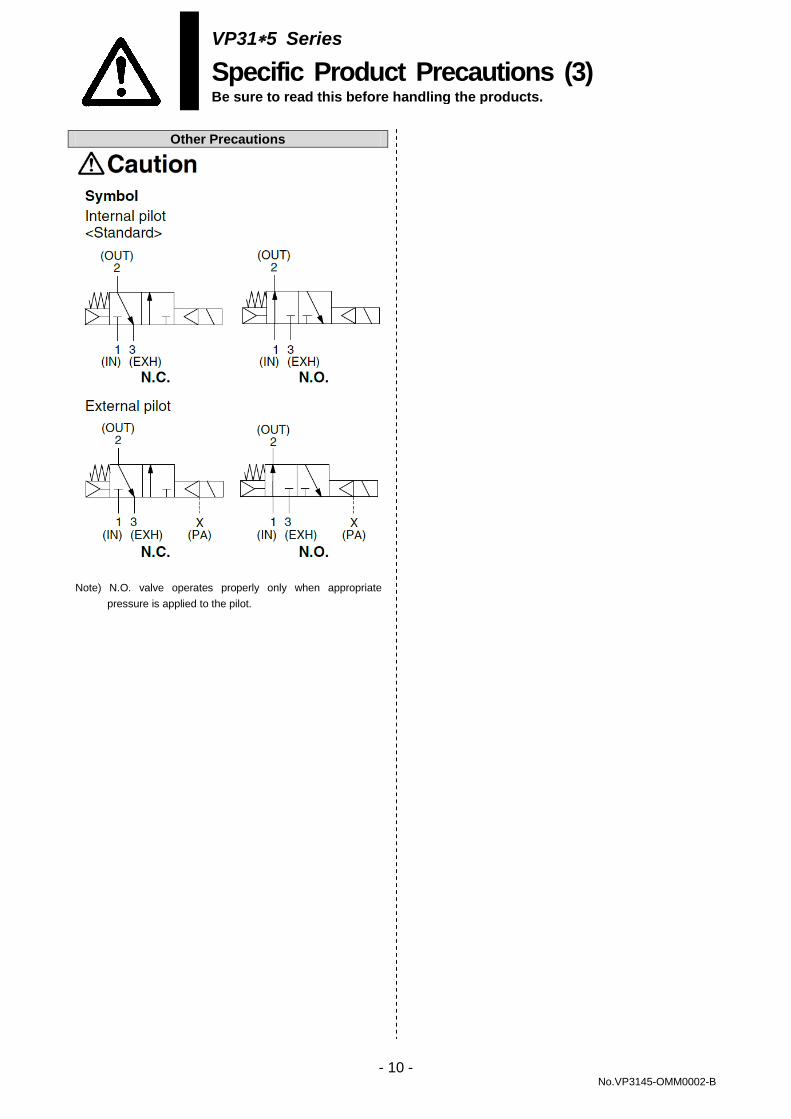
Specific Product Precautions (3) Be sure to read this before handling the products.
Other Precautions Note) N.O. valve operates properly only when appropriate
pressure is applied to the pilot.
- 10 - No.VP3145-OMM0002-B
VP31∗5 Series
Specific Product Precautions (4) Be sure to read this before handling the products.
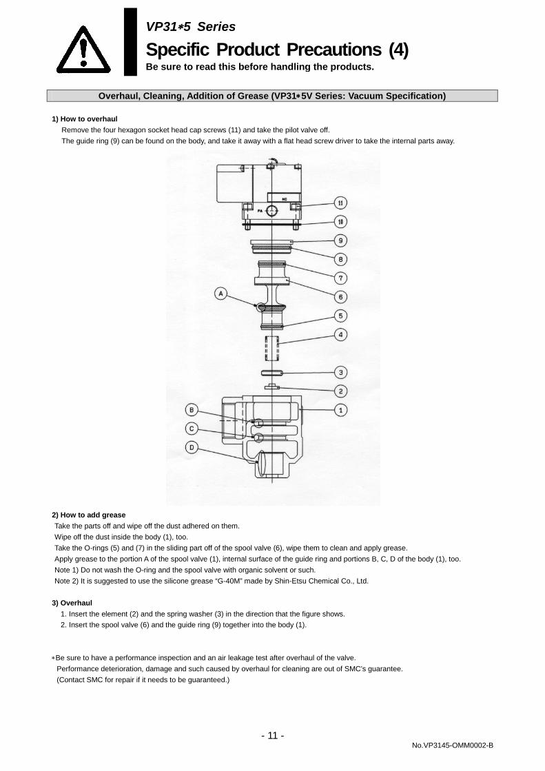
Overhaul, Cleaning, Addition of Grease (VP31∗5V Series: Vacuum Specification) 1) How to overhaul
Remove the four hexagon socket head cap screws (11) and take the pilot valve off. The guide ring (9) can be found on the body, and take it away with a flat head screw driver to take the internal parts away.
2) How to add grease Take the parts off and wipe off the dust adhered on them. Wipe off the dust inside the body (1), too. Take the O-rings (5) and (7) in the sliding part off of the spool valve (6), wipe them to clean and apply grease. Apply grease to the portion A of the spool valve (1), internal surface of the guide ring and portions B, C, D of the body (1), too. Note 1) Do not wash the O-ring and the spool valve with organic solvent or such. Note 2) It is suggested to use the silicone grease “G-40M” made by Shin-Etsu Chemical Co., Ltd.
3) Overhaul
1. Insert the element (2) and the spring washer (3) in the direction that the figure shows. 2. Insert the spool valve (6) and the guide ring (9) together into the body (1).
∗Be sure to have a performance inspection and an air leakage test after overhaul of the valve.
Performance deterioration, damage and such caused by overhaul for cleaning are out of SMC’s guarantee. (Contact SMC for repair if it needs to be guaranteed.)
- 11 - No.VP3145-OMM0002-B
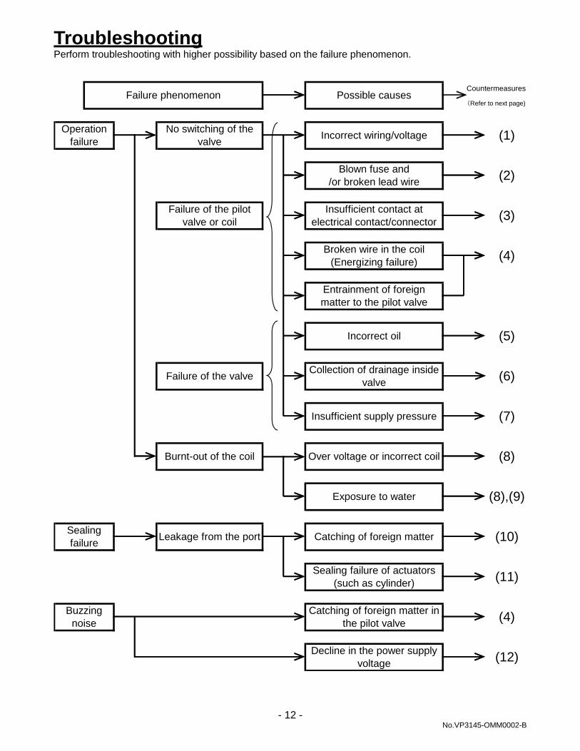
Troubleshooting Perform troubleshooting with higher possibility based on the failure phenomenon.
Buzzingnoise
Catching of foreign matter inthe pilot valve (4)
Decline in the power supplyvoltage (12)
Sealingfailure Leakage from the port Catching of foreign matter (10)
Sealing failure of actuators(such as cylinder) (11)
Insufficient supply pressure (7)
Burnt-out of the coil Over voltage or incorrect coil (8)
Exposure to water (8),(9)
Entrainment of foreignmatter to the pilot valve
Incorrect oil (5)
Collection of drainage insidevalve (6)Failure of the valve
Blown fuse and/or broken lead wire (2)
Failure of the pilotvalve or coil
Insufficient contact atelectrical contact/connector (3)
Broken wire in the coil(Energizing failure) (4)
Failure phenomenon Possible causes
Operationfailure
No switching of thevalve Incorrect wiring/voltage (1)
(Refer to next page)
Countermeasures
- 12 - No.VP3145-OMM0002-B
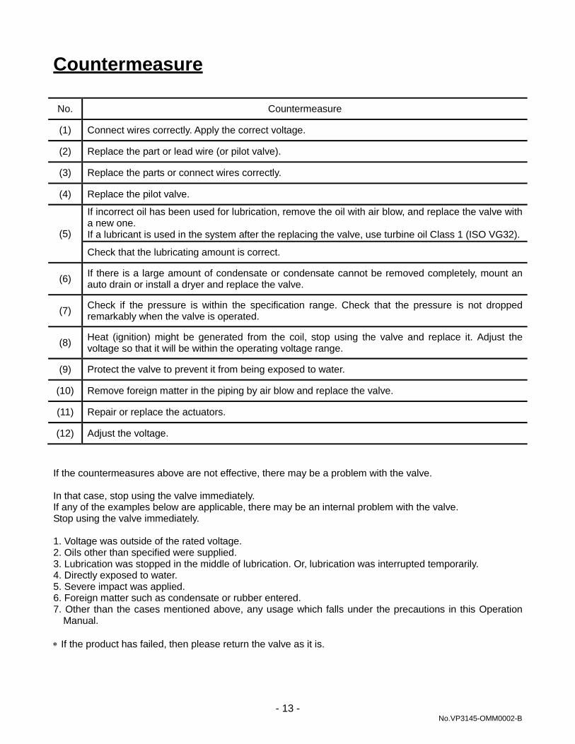
Countermeasure
No. Countermeasure
(1) Connect wires correctly. Apply the correct voltage.
(2) Replace the part or lead wire (or pilot valve).
(3) Replace the parts or connect wires correctly.
(4) Replace the pilot valve.
(5)
If incorrect oil has been used for lubrication, remove the oil with air blow, and replace the valve with a new one. If a lubricant is used in the system after the replacing the valve, use turbine oil Class 1 (ISO VG32).
Check that the lubricating amount is correct.
(6) If there is a large amount of condensate or condensate cannot be removed completely, mount an auto drain or install a dryer and replace the valve.
(7) Check if the pressure is within the specification range. Check that the pressure is not dropped remarkably when the valve is operated.
(8) Heat (ignition) might be generated from the coil, stop using the valve and replace it. Adjust the voltage so that it will be within the operating voltage range.
(9) Protect the valve to prevent it from being exposed to water.
(10) Remove foreign matter in the piping by air blow and replace the valve.
(11) Repair or replace the actuators.
(12) Adjust the voltage.
If the countermeasures above are not effective, there may be a problem with the valve. In that case, stop using the valve immediately. If any of the examples below are applicable, there may be an internal problem with the valve. Stop using the valve immediately. 1. Voltage was outside of the rated voltage. 2. Oils other than specified were supplied. 3. Lubrication was stopped in the middle of lubrication. Or, lubrication was interrupted temporarily. 4. Directly exposed to water. 5. Severe impact was applied. 6. Foreign matter such as condensate or rubber entered. 7. Other than the cases mentioned above, any usage which falls under the precautions in this Operation
Manual. ∗ If the product has failed, then please return the valve as it is.
- 13 - No.VP3145-OMM0002-B
Revision
□AE A RENEWAL 2018.12
4-14-1, Sotokanda, Chiyoda-ku, Tokyo 101-0021 JAPAN Tel: + 81 3 5207 8249 Fax: +81 3 5298 5362 URL http://www.smcworld.com Note: Specifications are subject to change without prior notice and any obligation on the part of the manufacturer. © 2018 SMC Corporation All Rights Reserved
No.VP3145-OMM0002-B