Embed Size (px)
Citation preview
OWNER’S MANUAL
For use with RAMCHECK LX Base Tester RAMCHECK LX DDR3/DDR2/DDR1 RAMCHECK LX DDR3/DDR2 RAMCHECK LX DDR2/DDR1 RAMCHECK LX DDR3 RAMCHECK LX DDR2 RAMCHECK LX DDR1
99 Washington Street Melrose, MA 02176 Phone 781-665-1400Toll Free 1-800-517-8431
Visit us at www.TestEquipmentDepot.com
RAMCHECK LX OWNER’S MANUAL
RAMCHECK LX OWNER’S MANUAL PREFACE
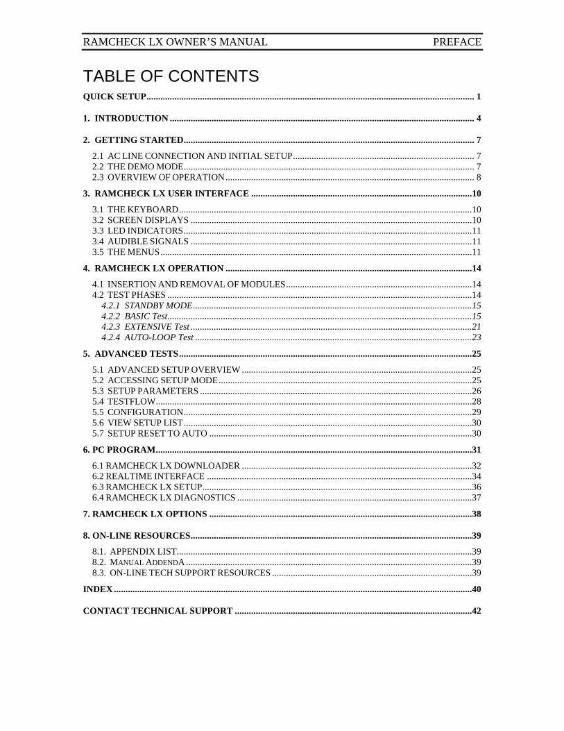
TABLE OF CONTENTS QUICK SETUP ............................................................................................................................................. 1
1. INTRODUCTION ................................................................................................................................... 4
2. GETTING STARTED ............................................................................................................................. 7
2.1 AC LINE CONNECTION AND INITIAL SETUP .............................................................................. 7 2.2 THE DEMO MODE ............................................................................................................................. 7 2.3 OVERVIEW OF OPERATION ........................................................................................................... 8
3. RAMCHECK LX USER INTERFACE ...............................................................................................10
3.1 THE KEYBOARD ..............................................................................................................................10 3.2 SCREEN DISPLAYS .........................................................................................................................10 3.3 LED INDICATORS ............................................................................................................................11 3.4 AUDIBLE SIGNALS .........................................................................................................................11 3.5 THE MENUS ......................................................................................................................................11
4. RAMCHECK LX OPERATION ..........................................................................................................14
4.1 INSERTION AND REMOVAL OF MODULES ................................................................................14 4.2 TEST PHASES ...................................................................................................................................14
4.2.1 STANDBY MODE ........................................................................................................................15 4.2.2 BASIC Test...................................................................................................................................15 4.2.3 EXTENSIVE Test .........................................................................................................................21 4.2.4 AUTO-LOOP Test .......................................................................................................................23
5. ADVANCED TESTS ..............................................................................................................................25
5.1 ADVANCED SETUP OVERVIEW ...................................................................................................25 5.2 ACCESSING SETUP MODE .............................................................................................................25 5.3 SETUP PARAMETERS .....................................................................................................................26 5.4 TESTFLOW ........................................................................................................................................28 5.5 CONFIGURATION ............................................................................................................................29 5.6 VIEW SETUP LIST ............................................................................................................................30 5.7 SETUP RESET TO AUTO .................................................................................................................30
6. PC PROGRAM ........................................................................................................................................31
6.1 RAMCHECK LX DOWNLOADER ...................................................................................................32 6.2 REALTIME INTERFACE ..................................................................................................................34 6.3 RAMCHECK LX SETUP ....................................................................................................................36 6.4 RAMCHECK LX DIAGNOSTICS .....................................................................................................37
7. RAMCHECK LX OPTIONS .................................................................................................................38
8. ON-LINE RESOURCES .........................................................................................................................39
8.1. APPENDIX LIST...............................................................................................................................39 8.2. MANUAL ADDENDA ...........................................................................................................................39 8.3. ON-LINE TECH SUPPORT RESOURCES ......................................................................................39
INDEX ..........................................................................................................................................................40
CONTACT TECHNICAL SUPPORT ......................................................................................................42
RAMCHECK LX OWNER’S MANUAL PREFACE
PAGE 1
QUICK SETUP
If you hate to read manuals and cannot wait to use your RAMCHECK LX with its various options, here is a quick short cut:
Connect the power supply to RAMCHECK LX and to the AC line. Adapters may be mounted or removed only while the RAMCHECK LX power switch is OFF.
Turn the tester on and press F3 for the DEMO PROGRAM that describes the basic functions.
Insert and remove memory modules only when the MODULE POWER red LED is OFF.
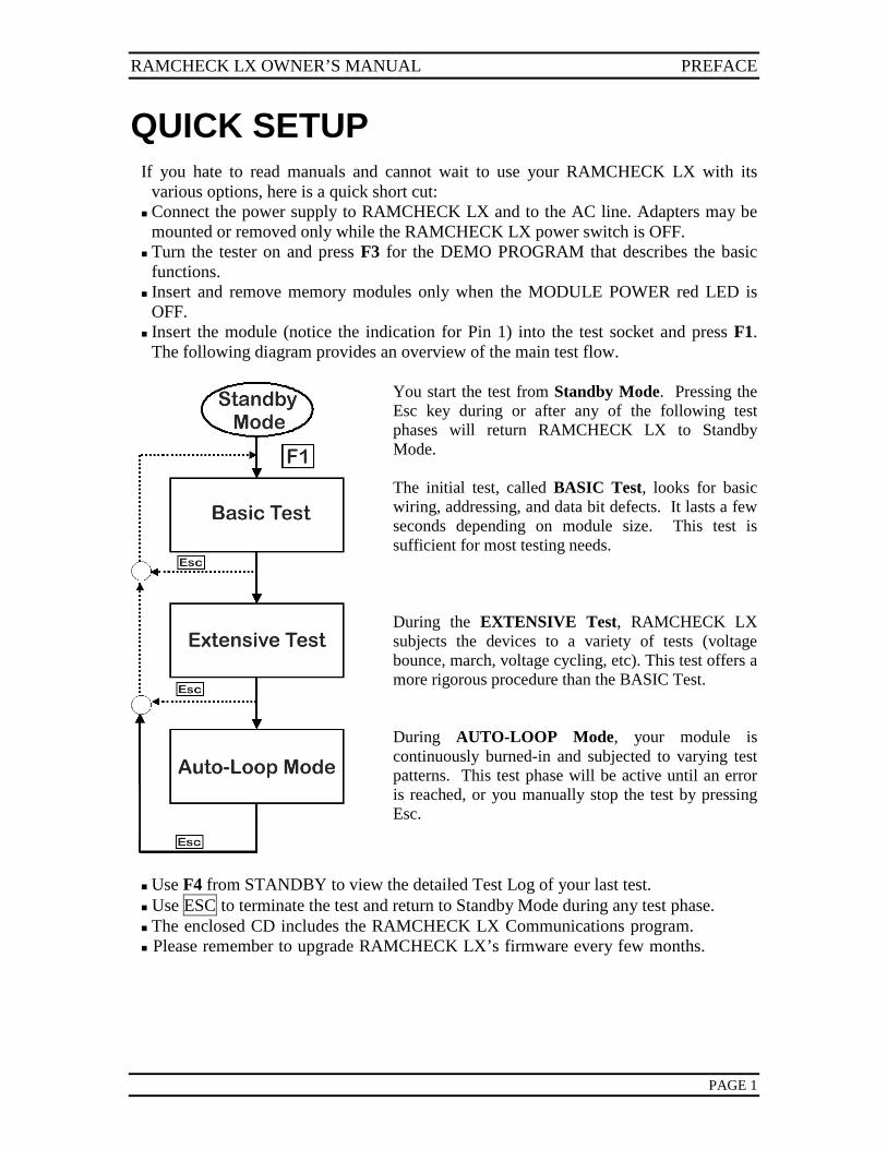
Insert the module (notice the indication for Pin 1) into the test socket and press F1. The following diagram provides an overview of the main test flow.
You start the test from Standby Mode. Pressing the Esc key during or after any of the following test phases will return RAMCHECK LX to Standby Mode. The initial test, called BASIC Test, looks for basic wiring, addressing, and data bit defects. It lasts a few seconds depending on module size. This test is sufficient for most testing needs. During the EXTENSIVE Test, RAMCHECK LX subjects the devices to a variety of tests (voltage bounce, march, voltage cycling, etc). This test offers a more rigorous procedure than the BASIC Test. During AUTO-LOOP Mode, your module is continuously burned-in and subjected to varying test patterns. This test phase will be active until an error is reached, or you manually stop the test by pressing Esc.
Use F4 from STANDBY to view the detailed Test Log of your last test. Use ESC to terminate the test and return to Standby Mode during any test phase. The enclosed CD includes the RAMCHECK LX Communications program. Please remember to upgrade RAMCHECK LX’s firmware every few months.
RAMCHECK LX OWNER’S MANUAL
PAGE 2
This manual is applicable to all RAMCHECK LX configurations with firmware versions 3.18 and above. The firmware version is displayed when RAMCHECK LX is turned on. Printed 1-10-2012. RAMCHECK, SIMCHECK, DIMMCHECK, and INNOVENTIONS are registered trademarks of INNOVENTIONS, Inc. All other trademarks belong to their legal owners. Copyright 1996, 2012 by INNOVENTIONS, Inc. All rights reserved. RAMCHECK LX, RAMCHECK, SIMCHECK and SIMCHECK II were invented by Dr. David Y. Feinstein and its patent is licensed to INNOVENTIONS, Inc. Special credits: Hardware and Software Development: Dr. David Y. Feinstein. R&D Assistants: Calvin Mikeska Jr. and Jose Nunez. Production Design Assistant: Sylvia Greer. Product Packaging Design Assistant: Janie DeMontoya. Manual Authors: Dr. David Y. Feinstein and Scott LaRoche. Photography: Scott LaRoche. Legacy RAMCHECK Graphics Design: Angel Garcia.
SAFETY PRECAUTIONS WARNING: This instrument and the devices under test warm up significantly during
operation due to the high data rate of memory accesses. Keep away from combustible materials, in a well-ventilated and supervised area within an ambient temperature of 0oC to 27oC. Do not set it on top of other high temperature equipment. Make sure that tested modules are free from combustible materials and residues.
Never remove or insert a module when the Module Power is ON as indicated by the red LED indicator.
You MUST to turn RAMCHECK LX OFF before inserting or removing any optional test adapter.
Please let the unit cool down prior to removing adapter. For indoor use only. Never permit moisture to enter the interior of this instrument. Use standard anti-static precautions to avoid electro-static damage. The ZIF (Zero Insertion Force) test sockets on our products are expensive
components. Never permit moisture to enter the interior of these sockets. Never use excessive force to insert a module into the ZIF socket.
Never submit this instrument to a severe shock. Make sure that no conductive debris falls into any of the exposed sockets and
connectors. It can cause a short circuit that will disable the unit. Keep sockets clean to ensure proper contact.
RAMCHECK LX OWNER’S MANUAL PREFACE
PAGE 3
ONE YEAR LIMITED WARRANTY RAMCHECK LX and its optional adapters are warranted in entirety against any defects of material or workmanship which may develop for any reason whatsoever, except abuse and normal wear and tear of external test sockets, within a period of ONE YEAR following the date of purchase by the original purchaser. If your RAMCHECK LX should become defective within the warranty period, INNOVENTIONS, Inc. will repair it or elect to replace it free of charge. For warranty service, the purchaser or user must first call to obtain a Return Authorization Number as well as instructions on where to send the defective product, postage prepaid and insured, along with a return shipping charges and a proof of purchase. Except as stated above, INNOVENTIONS makes no warranty or representation, either expressed or implied, with respect to this product, its quality, performance, merchantability, or fitness for any particular purpose. INNOVENTIONS hereby specifically acknowledges the scientific fact that memory testers cannot achieve exhaustive tests (that is, 100% accuracy) due to the virtually unlimited possibilities of data combinations which may be stored inside a memory device. Therefore, while INNOVENTIONS continuously strives to improve its test algorithms, it cannot guarantee 100% accuracy of the test results. A detailed discussion of RAMCHECK LX’s accuracy is available on-line at:
In no event will INNOVENTIONS be liable for direct, indirect, special, incidental, or consequential damages resulting from any defect in this product. Some states do not allow limitations on how long an implied warranty lasts, or exclusion or limitation of incidental or consequential damages, so exclusions or limitations may not apply to you. This warranty gives you specific legal rights, and you may also have other legal rights, which vary, from state to state. INNOVENTIONS continuously develops new test programs and test adapters to support new memory types and variants of existing technologies. However, in view of the rapid emergence of new memory technologies, INNOVENTIONS cannot guarantee that the current product will be able to support all future memory devices. Product operation and specifications are subject to change without prior notice.
The License Agreement for the RAMCHECK LX PC Communications program appears in Appendix A.
1. INTRODUCTION RAMCHECK LX OWNER’S MANUAL
PAGE 4
1. INTRODUCTION RAMCHECK LX is the next generation memory tester from the
company that pioneered the portable RAM testing industry. The RAMCHECK LX product line is based on a powerful stand-alone processor, up-to-date high speed circuitry and advanced FPGA devices to provide enhanced testing capabilities. RAMCHECK LX and its adapters have been engineered to support DDR3, DDR2 and DDR1 memory devices as well as legacy SDRAM/EDO/FPM devices. Its built-in high speed test engine makes the capabilities of expensive desktop testers more affordable. The RAMCHECK LX is a major enhancement of our previous generation RAMCHECK tester and its line of products include the following systems: RAMCHECK LX DDR3 RAMCHECK LX DDR2 RAMCHECKLX DDR1 RAMCHECK LX base unit (works with all optional
RAMCHECK adapters) RAMCHECK LX DDR3/DDR2/DDR1 is our most comprehensive configuration which includes the RAMCHECK LX base tester, plus the DDR3, DDR2 and the DDR1 adapters. The DDR3 adapter supports testing of 240-pin PC3-6400, PC3-8500, and faster DDR3 modules. The DDR2 adapter supports testing of 240-pin PC2-3200, PC2-4300, PC2-5300/PC2-5400 and PC2-6400 DDR2 memory, including unbuffered and registered modules (ECC and non-ECC) that comply with JEDEC standards. The DDR1 adapter supports all popular 184-pin modules at 466/433/400/333/266/200Mhz. An optional 168-pin adapter for SDRAM and legacy EDO/FPM modules is also available. SDRAM support includes coverage for PC166/150/133/100/66 DIMMs, registered and non-registered modules. Our rich offering of optional adapters also supports DDR2 and DDR1 200-pin S.O. DIMMs, 144-pin SDRAM/EDO/FPM SO DIMMs, 100-pin S.O. DIMMs, individual DDR and SDRAM TSOP chips, as well as legacy 30-pin and 72-pin SIMM modules. (See Section 7). RAMCHECK LX’s user-friendly interface makes it easy to be used by non-technical personnel. More advanced users can control the test flow and parameters using the change-on-the-fly and the
RAMCHECK LX OWNER’S MANUAL 1. INTRODUCTION
PAGE 5
advanced setup features. Its test procedure is fully automatic, and its graphic LCD display shows clear instructions and test results. The special test sockets allow easy insertion and removal of the modules. Using our proprietary algorithms, RAMCHECK LX performs a thorough test on your memory module. All the memory chips on the module are tested simultaneously to detect errors that are caused by interference among the chips. RAMCHECK LX is not merely a go/no-go tester. It provides clear indications of faulty bits within a module, as well as other important repair related information.
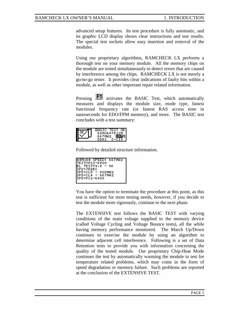
Pressing activates the BASIC Test, which automatically measures and displays the module size, mode type, fastest functional frequency rate (or fastest RAS access time in nanoseconds for EDO/FPM memory), and more. The BASIC test concludes with a test summary:
Followed by detailed structure information.
You have the option to terminate the procedure at this point, as this test is sufficient for most testing needs, however, if you decide to test the module more rigorously, continue to the next phase. The EXTENSIVE test follows the BASIC TEST with varying conditions of the main voltage supplied to the memory device (called Voltage Cycling and Voltage Bounce tests), all the while having memory performance monitored. The March Up/Down continues to exercise the module by using an algorithm to determine adjacent cell interference. Following is a set of Data Retention tests to provide you with information concerning the quality of the tested module. Our proprietary Chip-Heat Mode continues the test by automatically warming the module to test for temperature related problems, which may come in the form of speed degradation or memory failure. Such problems are reported at the conclusion of the EXTENSIVE TEST.
1. INTRODUCTION RAMCHECK LX OWNER’S MANUAL
PAGE 6
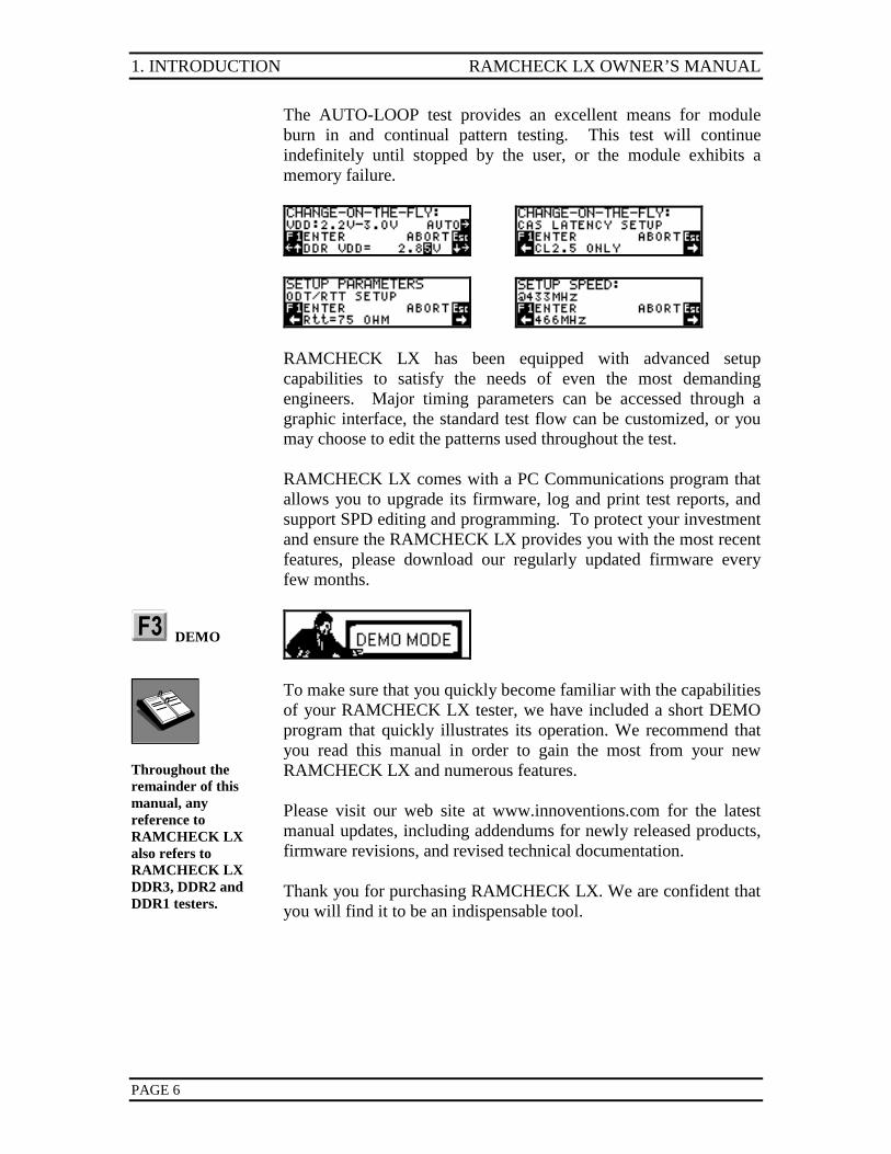
The AUTO-LOOP test provides an excellent means for module burn in and continual pattern testing. This test will continue indefinitely until stopped by the user, or the module exhibits a memory failure.
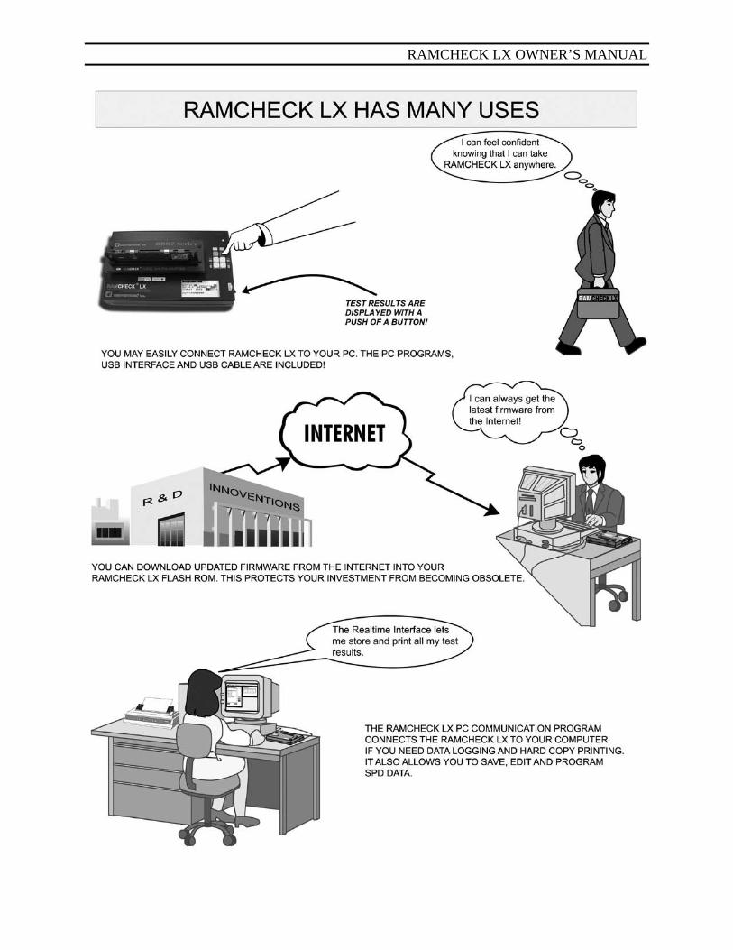
RAMCHECK LX has been equipped with advanced setup capabilities to satisfy the needs of even the most demanding engineers. Major timing parameters can be accessed through a graphic interface, the standard test flow can be customized, or you may choose to edit the patterns used throughout the test. RAMCHECK LX comes with a PC Communications program that allows you to upgrade its firmware, log and print test reports, and support SPD editing and programming. To protect your investment and ensure the RAMCHECK LX provides you with the most recent features, please download our regularly updated firmware every few months.
DEMO
Throughout the remainder of this manual, any reference to RAMCHECK LX also refers to RAMCHECK LX DDR3, DDR2 and DDR1 testers.
To make sure that you quickly become familiar with the capabilities of your RAMCHECK LX tester, we have included a short DEMO program that quickly illustrates its operation. We recommend that you read this manual in order to gain the most from your new RAMCHECK LX and numerous features. Please visit our web site at www.innoventions.com for the latest manual updates, including addendums for newly released products, firmware revisions, and revised technical documentation. Thank you for purchasing RAMCHECK LX. We are confident that you will find it to be an indispensable tool.
RAMCHECK LX OWNER’S MANUAL 2. GETTING STARTED
PAGE 7
2. GETTING STARTED 2.1 AC LINE CONNECTION AND INITIAL SETUP
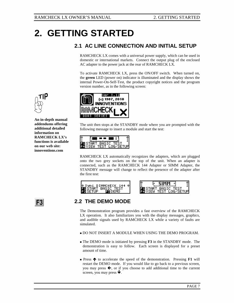
RAMCHECK LX comes with a universal power supply, which can be used in domestic or international markets. Connect the output plug of the enclosed AC adapter to the power jack at the rear of RAMCHECK LX. To activate RAMCHECK LX, press the ON/OFF switch. When turned on, the green LED (power on) indicator is illuminated and the display shows the internal Power-On-Self-Test, the product copyright notices and the program version number, as in the following screen:
An in-depth manual addendums offering additional detailed information on RAMCHECK LX’s functions is available on our web site: innoventions.com
The unit then stops at the STANDBY mode where you are prompted with the following message to insert a module and start the test:
RAMCHECK LX automatically recognizes the adapters, which are plugged onto the two grey sockets on the top of the unit. When an adapter is connected, such as the RAMCHECK 144 Adapter or SIMM Adapter, the STANDBY message will change to reflect the presence of the adapter after the first test:
2.2 THE DEMO MODE
The Demonstration program provides a fast overview of the RAMCHECK LX operation. It also familiarizes you with the display messages, graphics, and audible signals used by RAMCHECK LX while a variety of faults are simulated. DO NOT INSERT A MODULE WHEN USING THE DEMO PROGRAM. The DEMO mode is initiated by pressing F3 in the STANDBY mode. The
demonstration is easy to follow. Each screen is displayed for a preset amount of time.
Press to accelerate the speed of the demonstration. Pressing F1 will
restart the DEMO mode. If you would like to go back to a previous screen, you may press , or if you choose to add additional time to the current screen, you may press .
2. GETTING STARTED RAMCHECK LX OWNER’S MANUAL
PAGE 8
The DEMO mode incorporates portions of the actual program during which
the keys function in a prescribed way corresponding to the currently demonstrated feature. During such demonstrations, you may need to either press the ESC key to move on, or simply wait a few moments for the DEMO to continue on its own.
At the end of the demonstration, RAMCHECK LX returns to the
STANDBY mode. You may also leave the DEMO mode at any time by pressing ESC.
The RAMCHECK LX screen has eight lines of text, to improve visibility over our previous generation RAMCHECK products. However, when there is no risk of confusion, smaller screen versions may be used in this manual to conserve space.
2.3 OVERVIEW OF OPERATION
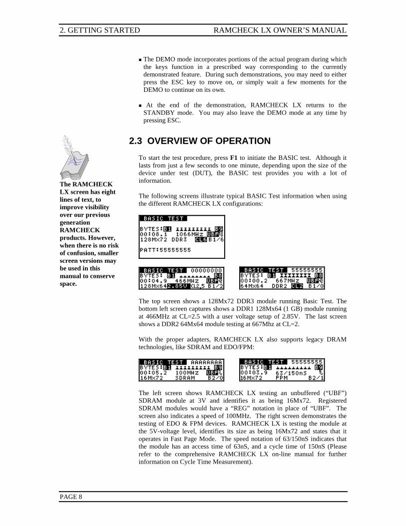
To start the test procedure, press F1 to initiate the BASIC test. Although it lasts from just a few seconds to one minute, depending upon the size of the device under test (DUT), the BASIC test provides you with a lot of information. The following screens illustrate typical BASIC Test information when using the different RAMCHECK LX configurations:
The top screen shows a 128Mx72 DDR3 module running Basic Test. The bottom left screen captures shows a DDR1 128Mx64 (1 GB) module running at 466MHz at CL=2.5 with a user voltage setup of 2.85V. The last screen shows a DDR2 64Mx64 module testing at 667Mhz at CL=2. With the proper adapters, RAMCHECK LX also supports legacy DRAM technologies, like SDRAM and EDO/FPM:
The left screen shows RAMCHECK LX testing an unbuffered (“UBF”) SDRAM module at 3V and identifies it as being 16Mx72. Registered SDRAM modules would have a “REG” notation in place of “UBF”. The screen also indicates a speed of 100MHz. The right screen demonstrates the testing of EDO & FPM devices. RAMCHECK LX is testing the module at the 5V-voltage level, identifies its size as being 16Mx72 and states that it operates in Fast Page Mode. The speed notation of 63/150nS indicates that the module has an access time of 63nS, and a cycle time of 150nS (Please refer to the comprehensive RAMCHECK LX on-line manual for further information on Cycle Time Measurement).
RAMCHECK LX OWNER’S MANUAL 2. GETTING STARTED
PAGE 9
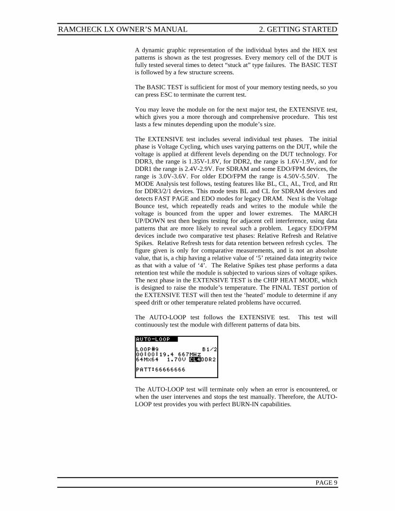
A dynamic graphic representation of the individual bytes and the HEX test patterns is shown as the test progresses. Every memory cell of the DUT is fully tested several times to detect “stuck at” type failures. The BASIC TEST is followed by a few structure screens. The BASIC TEST is sufficient for most of your memory testing needs, so you can press ESC to terminate the current test. You may leave the module on for the next major test, the EXTENSIVE test, which gives you a more thorough and comprehensive procedure. This test lasts a few minutes depending upon the module’s size. The EXTENSIVE test includes several individual test phases. The initial phase is Voltage Cycling, which uses varying patterns on the DUT, while the voltage is applied at different levels depending on the DUT technology. For DDR3, the range is 1.35V-1.8V, for DDR2, the range is 1.6V-1.9V, and for DDR1 the range is 2.4V-2.9V. For SDRAM and some EDO/FPM devices, the range is 3.0V-3.6V. For older EDO/FPM the range is 4.50V-5.50V. The MODE Analysis test follows, testing features like BL, CL, AL, Trcd, and Rtt for DDR3/2/1 devices. This mode tests BL and CL for SDRAM devices and detects FAST PAGE and EDO modes for legacy DRAM. Next is the Voltage Bounce test, which repeatedly reads and writes to the module while the voltage is bounced from the upper and lower extremes. The MARCH UP/DOWN test then begins testing for adjacent cell interference, using data patterns that are more likely to reveal such a problem. Legacy EDO/FPM devices include two comparative test phases: Relative Refresh and Relative Spikes. Relative Refresh tests for data retention between refresh cycles. The figure given is only for comparative measurements, and is not an absolute value, that is, a chip having a relative value of ‘5’ retained data integrity twice as that with a value of ‘4’. The Relative Spikes test phase performs a data retention test while the module is subjected to various sizes of voltage spikes. The next phase in the EXTENSIVE TEST is the CHIP HEAT MODE, which is designed to raise the module’s temperature. The FINAL TEST portion of the EXTENSIVE TEST will then test the ‘heated’ module to determine if any speed drift or other temperature related problems have occurred. The AUTO-LOOP test follows the EXTENSIVE test. This test will continuously test the module with different patterns of data bits.
The AUTO-LOOP test will terminate only when an error is encountered, or when the user intervenes and stops the test manually. Therefore, the AUTO-LOOP test provides you with perfect BURN-IN capabilities.
3. RAMCHECK LX USER INTERFACE RAMCHECK LX OWNER’S MANUAL
PAGE 10
3. RAMCHECK LX USER INTERFACE
This section introduces you to the various aspects of the RAMCHECK LX user interface. It outlines the use of the keyboard, explains the screen display and the audio signals, and it illustrates some of the menus you will encounter. 3.1 THE KEYBOARD
The RAMCHECK LX keyboard consists of six keys, which are pressed momentarily to perform a function. The firmware changes the function of these keys depending on the mode of operation. ESC: is always used to EXIT or ABORT the current mode. F1: is typically the ACTION switch. Additionally, F1 can be used by various menus for item selection, skipping a pause or a specific test, and for other activities. F2 : is used for menu navigation or for menu item selection. When used for menu navigation it moves the cursor or scrolls a full string one to the left. This key can also be used to repeat a previous test phase during the Extensive Test. F3 : is used for menu navigation, variable setup, or for menu item selection. When used for menu navigation it moves your selection up. When used for variable setup it increments the variable. This switch is also used to accelerate (minimize) various delays in the program. F4 : is used for menu navigation, variable setup, or for menu item selection. When used for menu navigation it moves your selection down. When used for variable setup it decrements the variable. This switch is also used to slow down (maximize) various delays in the program. F5 : is used for menu navigation or for menu item selection. When used for menu navigation it moves the cursor or scrolls a full string one to the right. In the following discussions, we will refer to the dual function keys as F2-F5 or by their arrow marks.
3.2 SCREEN DISPLAYS
RAMCHECK LX utilizes an advanced 128x64 high contrast graphic LCD display with back lighting for improved visibility.
INSTRUCTION MENUS: Instruction menus display the potential choices
for your next step (recall that in addition to the displayed choices, you can always press ESC). If no selection is made, a default alternative is chosen during a test procedure after a preset period of time; for setup menus, the display will remain until the user has selected one of the choices shown.
RAMCHECK LX OWNER’S MANUAL 3. RAMCHECK LX USER INTERFACE
PAGE 11
REAL-TIME TEST RESULTS: Many test results, like size, speed, mode and other information are determined by RAMCHECK LX at the start of the BASIC test and during most other tests. These results are immediately posted on the screen for your review. We also use animation characters to give you a relative indication of several tests’ progress, and a test timer to show you the length of the test.
3.3 LED INDICATORS
RAMCHECK LX is equipped with five LED indicators:
Adapters can be replaced only when the main power is OFF!
MAIN POWER: This green LED indicates that the instrument power is ON and is controlled by the OFF/ON switch.
Module Power must be off when inserting and removing modules.
MODULE POWER: This red LED is turned on during the actual memory test, indicating that electrical power is applied to the module. BURST: This amber LED indicates that a special bursting test is active. TEST ERROR: The red LED on the right side of the tester is turned on when a memory error is detected. It remains on until the next test is initiated. USB CONNECTION: This amber LED indicates that RAMCHECK LX is connected to the PC via the USB interface.
3.4 AUDIBLE SIGNALS
Audible signals are produced by RAMCHECK LX and are used throughout its operation. While various sound frequencies are used, errors are always indicated by lower frequency tones. After using RAMCHECK LX for a short time, you will learn to associate the signals with the corresponding messages displayed at the same time.
Additional menus are detailed on the RAMCHECK LX’s on-line manual addendums at: innoventions.com
3.5 THE MENUS
There are several menu styles that you are likely to encounter while working with RAMCHECK LX. Whenever possible, the program arranges the displayed menu keys to correspond to the actual keyboard layout. This section outlines some of the menus you are likely to encounter and providing you with information on how to navigate them.
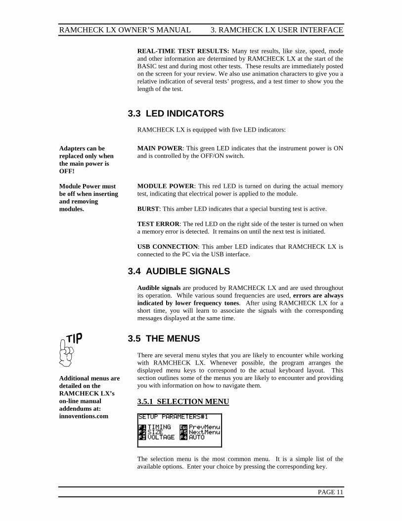
3.5.1 SELECTION MENU
The selection menu is the most common menu. It is a simple list of the available options. Enter your choice by pressing the corresponding key.
3. RAMCHECK LX USER INTERFACE RAMCHECK LX OWNER’S MANUAL
PAGE 12
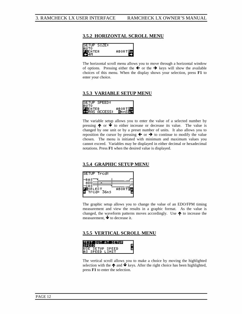
3.5.2 HORIZONTAL SCROLL MENU
The horizontal scroll menu allows you to move through a horizontal window of options. Pressing either the or the keys will show the available choices of this menu. When the display shows your selection, press F1 to enter your choice.
3.5.3 VARIABLE SETUP MENU
The variable setup allows you to enter the value of a selected number by pressing or to either increase or decrease its value. The value is changed by one unit or by a preset number of units. It also allows you to reposition the cursor by pressing or to continue to modify the value chosen. The menu is initiated with minimum and maximum values you cannot exceed. Variables may be displayed in either decimal or hexadecimal notations. Press F1 when the desired value is displayed.
3.5.4 GRAPHIC SETUP MENU
The graphic setup allows you to change the value of an EDO/FPM timing measurement and view the results in a graphic format. As the value is changed, the waveform patterns moves accordingly. Use to increase the measurement, to decrease it.
3.5.5 VERTICAL SCROLL MENU
The vertical scroll allows you to make a choice by moving the highlighted selection with the and keys. After the right choice has been highlighted, press F1 to enter the selection.
RAMCHECK LX OWNER’S MANUAL 3. RAMCHECK LX USER INTERFACE
PAGE 13
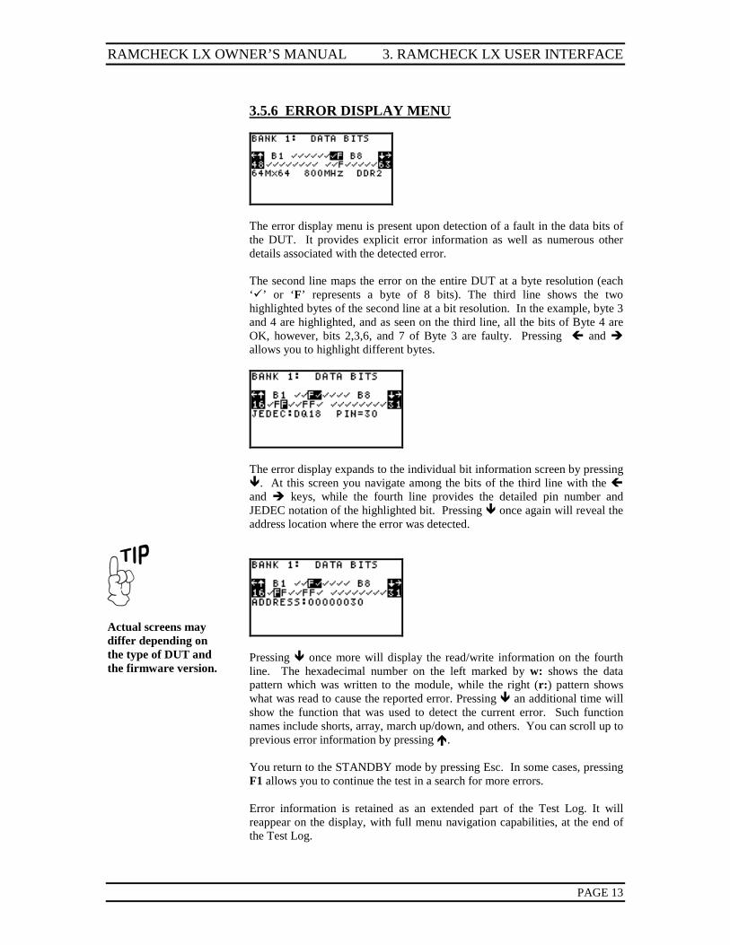
3.5.6 ERROR DISPLAY MENU
The error display menu is present upon detection of a fault in the data bits of the DUT. It provides explicit error information as well as numerous other details associated with the detected error. The second line maps the error on the entire DUT at a byte resolution (each ‘’ or ‘F’ represents a byte of 8 bits). The third line shows the two highlighted bytes of the second line at a bit resolution. In the example, byte 3 and 4 are highlighted, and as seen on the third line, all the bits of Byte 4 are OK, however, bits 2,3,6, and 7 of Byte 3 are faulty. Pressing and allows you to highlight different bytes.
The error display expands to the individual bit information screen by pressing . At this screen you navigate among the bits of the third line with the and keys, while the fourth line provides the detailed pin number and JEDEC notation of the highlighted bit. Pressing once again will reveal the address location where the error was detected.
Actual screens may differ depending on the type of DUT and the firmware version.
Pressing once more will display the read/write information on the fourth line. The hexadecimal number on the left marked by w: shows the data pattern which was written to the module, while the right (r:) pattern shows what was read to cause the reported error. Pressing an additional time will show the function that was used to detect the current error. Such function names include shorts, array, march up/down, and others. You can scroll up to previous error information by pressing . You return to the STANDBY mode by pressing Esc. In some cases, pressing F1 allows you to continue the test in a search for more errors. Error information is retained as an extended part of the Test Log. It will reappear on the display, with full menu navigation capabilities, at the end of the Test Log.
4. RAMCHECK LX OPERATION RAMCHECK LX OWNER’S MANUAL
PAGE 14
4. RAMCHECK LX OPERATION This section outlines the operation of RAMCHECK LX. It instructs you on
how to handle the test sockets, and describes the RAMCHECK LX tests in some detail. Please note that actual screen displays may vary as RAMCHECK LX’s firmware is modified, or if you swap adapters.
CAUTION
1. Do not insert or
remove a module when the Module Power red LED is on! (Press ESC to turn it off prior to insertion/removal.)
2. Never use excessive
force to insert a DIMM module. If a module is not sliding in smoothly - please review the manual addendum for the adapter in the ON-LINE Resources listed in Section 8.
4.1 INSERTION AND REMOVAL OF MODULES
INSERTION: Make sure the Module Power red LED on the front of the RAMCHECK LX is off (if not - press ESC). RAMCHECK LX adapters use vertically mounted high-quality test sockets with two ejectors that need to be opened prior to insertion. Carefully insert the DIMM into the socket, pushing it evenly along its top. When the DIMM is properly inserted, the ejectors will snap onto the semi-circular notches on each side of the module. REMOVAL: Make sure that the Module Power red LED is off (if not - press ESC). In certain modules, the red LED may still be glowing slightly, even when the tester is in Standby Mode; if this occurs, it is still safe to remove the module from the socket (only in Standby Mode), as the module is allowing only a minor amount of leakage current to flow. This however, should not be interpreted as an indication of a defective device. Place one finger on top of the DIMM module to prevent the module from popping upward and simultaneously pull both ejectors sideways.
NOTE: The socket used is of the best available quality. It is rated for 10,000 to 20,000 insertion/removal cycles. Using it carefully will provide you with a long period of use. In particular, do not subject it to humidity and always follow the above instructions for smooth handling.
Replacement test socket are available for purchase. (Please note that inexpensive converters are available for certain SODIMMs and chips. These converters do not use the rugged sockets found on the adapters.)
4.2 TEST PHASES
The main tests performed by the RAMCHECK LX, including the BASIC test, the EXTENSIVE test and the AUTO-LOOP, are MULTI-BYTE tests where all the data bus bits are checked simultaneously. RAMCHECK LX starts with the BASIC test, which lasts between 3 and 60 seconds, depending on module size and type. The EXTENSIVE test automatically follows the BASIC test and it lasts several minutes. It includes different voltage and temperature related test procedures, as well as mode analysis. The AUTO-LOOP test proceeds in an endless loop of varying pattern (and algorithm) tests.
RAMCHECK LX OWNER’S MANUAL 4. RAMCHECK LX OPERATION
PAGE 15
Section 5 describes the RAMCHECK LX SETUP mode, which allows you to perform advanced tests in which you setup your own parameters and testflow.
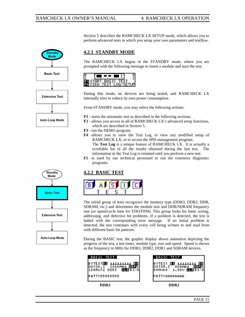
4.2.1 STANDBY MODE The RAMCHECK LX begins in the STANDBY mode, where you are prompted with the following message to insert a module and start the test:
During this mode, no devices are being tested, and RAMCHECK LX internally tries to reduce its own power consumption. From STANDBY mode, you may select the following actions: F1 - starts the automatic test as described in the following sections. F2 - allows you access to all of RAMCHECK LX’s advanced setup functions,
which are described in Section 5. F3 - run the DEMO program. F4 -allows you to view the Test Log, to view any modified setup of
RAMCHECK LX, or to access the SPD management program. The Test Log is a unique feature of RAMCHECK LX. It is actually a scrollable list of all the results obtained during the last test. The information in the Test Log is retained until you perform a new test.
F5 -is used by our technical personnel to run the extensive diagnostic programs.
4.2.2 BASIC TEST
The initial group of tests recognizes the memory type (DDR3, DDR2, DDR, SDRAM, etc.) and determines the module size and DDR/SDRAM frequency rate (or speed/cycle time for EDO/FPM). This group looks for basic wiring, addressing, and defective bit problems. If a problem is detected, the test is halted with the corresponding error message. If no initial problem is detected, the test continues with every cell being written to and read from with different basic bit patterns. During the BASIC test, the graphic display shows animation depicting the progress of the test, a test timer, module type, size and speed. Speed is shown as the frequency in MHz for DDR3, DDR2, DDR1 and SDRAM devices.
DDR3 DDR2
4. RAMCHECK LX OPERATION RAMCHECK LX OWNER’S MANUAL
PAGE 16
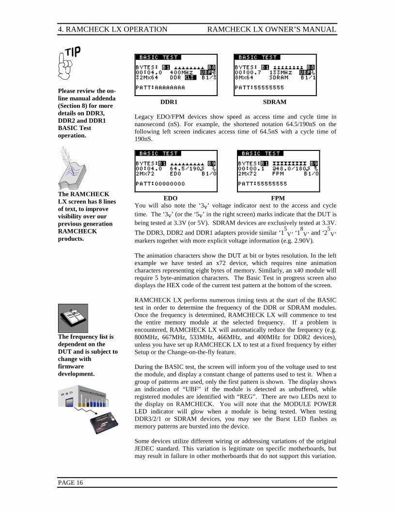
Please review the on-line manual addenda (Section 8) for more details on DDR3, DDR2 and DDR1 BASIC Test operation.
The RAMCHECK LX screen has 8 lines of text, to improve visibility over our previous generation RAMCHECK products.
DDR1 SDRAM Legacy EDO/FPM devices show speed as access time and cycle time in nanosecond (nS). For example, the shortened notation 64.5/190nS on the following left screen indicates access time of 64.5nS with a cycle time of 190nS.
EDO FPM You will also note the ‘3v’ voltage indicator next to the access and cycle time. The ‘3v’ (or the ‘5v’ in the right screen) marks indicate that the DUT is being tested at 3.3V (or 5V). SDRAM devices are exclusively tested at 3.3V. The DDR3, DDR2 and DDR1 adapters provide similar ‘15
V’ ‘18
V’ and ‘25V’
markers together with more explicit voltage information (e.g. 2.90V). The animation characters show the DUT at bit or bytes resolution. In the left example we have tested an x72 device, which requires nine animation characters representing eight bytes of memory. Similarly, an x40 module will require 5 byte-animation characters. The Basic Test in progress screen also displays the HEX code of the current test pattern at the bottom of the screen.
The frequency list is dependent on the DUT and is subject to change with firmware development.
RAMCHECK LX performs numerous timing tests at the start of the BASIC test in order to determine the frequency of the DDR or SDRAM modules. Once the frequency is determined, RAMCHECK LX will commence to test the entire memory module at the selected frequency. If a problem is encountered, RAMCHECK LX will automatically reduce the frequency (e.g. 800MHz, 667MHz, 533MHz, 466MHz, and 400MHz for DDR2 devices), unless you have set up RAMCHECK LX to test at a fixed frequency by either Setup or the Change-on-the-fly feature. During the BASIC test, the screen will inform you of the voltage used to test the module, and display a constant change of patterns used to test it. When a group of patterns are used, only the first pattern is shown. The display shows an indication of “UBF” if the module is detected as unbuffered, while registered modules are identified with “REG”. There are two LEDs next to the display on RAMCHECK. You will note that the MODULE POWER LED indicator will glow when a module is being tested. When testing DDR3/2/1 or SDRAM devices, you may see the Burst LED flashes as memory patterns are bursted into the device. Some devices utilize different wiring or addressing variations of the original JEDEC standard. This variation is legitimate on specific motherboards, but may result in failure in other motherboards that do not support this variation.
RAMCHECK LX OWNER’S MANUAL 4. RAMCHECK LX OPERATION
PAGE 17
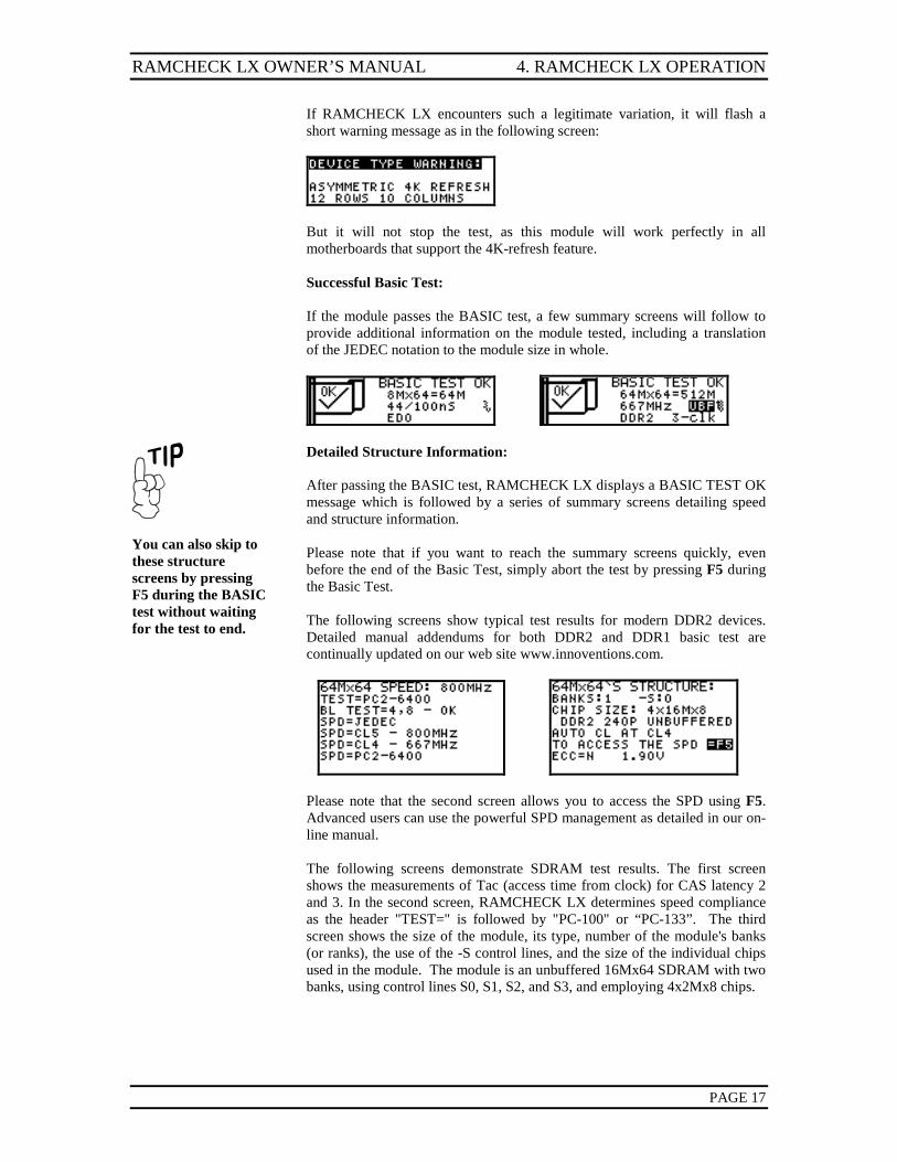
If RAMCHECK LX encounters such a legitimate variation, it will flash a short warning message as in the following screen:
But it will not stop the test, as this module will work perfectly in all motherboards that support the 4K-refresh feature.
Successful Basic Test: If the module passes the BASIC test, a few summary screens will follow to provide additional information on the module tested, including a translation of the JEDEC notation to the module size in whole.
You can also skip to these structure screens by pressing F5 during the BASIC test without waiting for the test to end.
Detailed Structure Information: After passing the BASIC test, RAMCHECK LX displays a BASIC TEST OK message which is followed by a series of summary screens detailing speed and structure information. Please note that if you want to reach the summary screens quickly, even before the end of the Basic Test, simply abort the test by pressing F5 during the Basic Test. The following screens show typical test results for modern DDR2 devices. Detailed manual addendums for both DDR2 and DDR1 basic test are continually updated on our web site www.innoventions.com.
Please note that the second screen allows you to access the SPD using F5. Advanced users can use the powerful SPD management as detailed in our on-line manual. The following screens demonstrate SDRAM test results. The first screen shows the measurements of Tac (access time from clock) for CAS latency 2 and 3. In the second screen, RAMCHECK LX determines speed compliance as the header "TEST=" is followed by "PC-100" or “PC-133”. The third screen shows the size of the module, its type, number of the module's banks (or ranks), the use of the -S control lines, and the size of the individual chips used in the module. The module is an unbuffered 16Mx64 SDRAM with two banks, using control lines S0, S1, S2, and S3, and employing 4x2Mx8 chips.
4. RAMCHECK LX OPERATION RAMCHECK LX OWNER’S MANUAL
PAGE 18
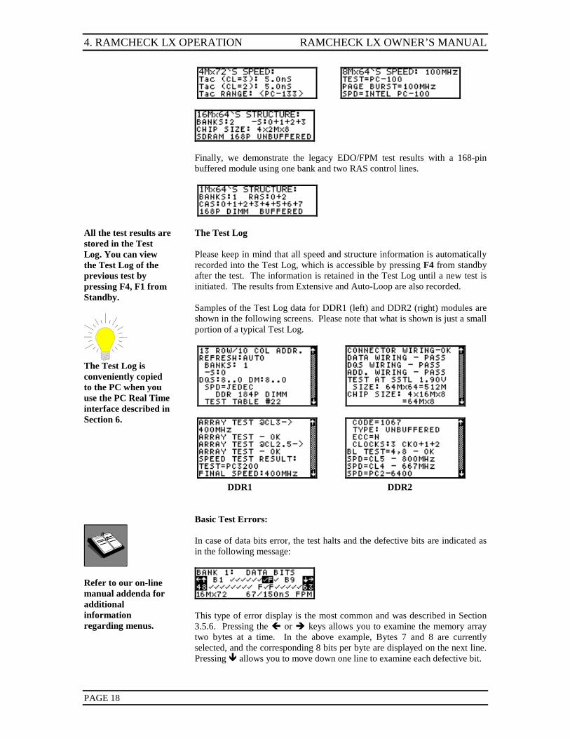
Finally, we demonstrate the legacy EDO/FPM test results with a 168-pin buffered module using one bank and two RAS control lines.
All the test results are stored in the Test Log. You can view the Test Log of the previous test by pressing F4, F1 from Standby.
The Test Log is conveniently copied to the PC when you use the PC Real Time interface described in Section 6.
The Test Log Please keep in mind that all speed and structure information is automatically recorded into the Test Log, which is accessible by pressing F4 from standby after the test. The information is retained in the Test Log until a new test is initiated. The results from Extensive and Auto-Loop are also recorded. Samples of the Test Log data for DDR1 (left) and DDR2 (right) modules are shown in the following screens. Please note that what is shown is just a small portion of a typical Test Log.
DDR1 DDR2
Refer to our on-line manual addenda for additional information regarding menus.
Basic Test Errors: In case of data bits error, the test halts and the defective bits are indicated as in the following message:
This type of error display is the most common and was described in Section 3.5.6. Pressing the or keys allows you to examine the memory array two bytes at a time. In the above example, Bytes 7 and 8 are currently selected, and the corresponding 8 bits per byte are displayed on the next line. Pressing allows you to move down one line to examine each defective bit.
RAMCHECK LX OWNER’S MANUAL 4. RAMCHECK LX OPERATION
PAGE 19
The RAMCHECK LX test program uses a very large number of error messages and test results. Only a small portion of them are detailed in this section. Additional error messages are listed on the application note section of our web site: Innoventions.com
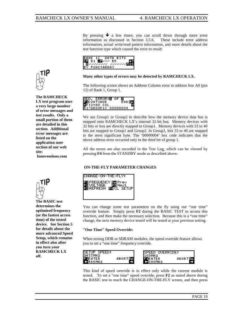
By pressing a few times, you can scroll down through more error information as discussed in Section 3.5.6. These include error address information, actual write/read pattern information, and more details about the test function type which caused the error to result:
Many other types of errors may be detected by RAMCHECK LX. The following screen shows an Address Column error in address line A0 (pin 12) of Bank 1, Group 1.
We use Group1 or Group2 to describe how the memory device data bus is mapped onto RAMCHECK LX’s internal 32-bit bus. Memory devices with 32 bits or less are directly mapped to Group1. Memory devices with 33 to 40 bits are mapped to Group1 and Group2. In Group2, bits 33 to 40 are mapped to the most significant byte. The ‘00000004’ hex code indicates that the above address error occurred only in the third bit of group 1. All the errors are also recorded in the Test Log, which can be viewed by pressing F4 from the STANDBY mode as described above.
The BASIC test determines the optimized frequency (or the fastest access time) of the tested device. See Section 5 for details about the more advanced Speed Setup, which remains in effect also after you turn your RAMCHECK LX off.
ON-THE-FLY PARAMETER CHANGES
You can change some test parameters on the fly using our “one time” override feature. Simply press F2 during the BASIC TEST to access this function, and then make the necessary selection. Because this is a “one time” change, the next memory device tested will be tested at your previous setting. "One Time" Speed Override: When testing DDR or SDRAM modules, the speed override feature allows you to set a “one time” frequency override.
This kind of speed override is in effect only while the current module is tested. To set a "one time" speed override, press F2 as stated above during the BASIC test to reach the CHANGE-ON-THE-FLY screen, and then press
4. RAMCHECK LX OPERATION RAMCHECK LX OWNER’S MANUAL
PAGE 20
F1 to select SPEED. Use the and keys to scroll through the available frequency rates. When testing EDO/FPM modules, the speed override feature allows a “one time” change of nanosecond access time from RAS. Enter the speed override by pressing F2 during the Basic Test and select Speed.
Afterwards, use the or to position the cursor over the current speed and then press either the or keys to increase or decrease the value. Press F1 to enter your selected speed. Thereafter, subsequent test phases will be conducted at the selected speed, as displayed on the screen with an "@" marker. Please note that when modules are detected as being 3V devices (e.g. SDRAM), RAMCHECK LX will not allow you to alter the voltage using the changed-on-the-fly feature.
Next Phase:
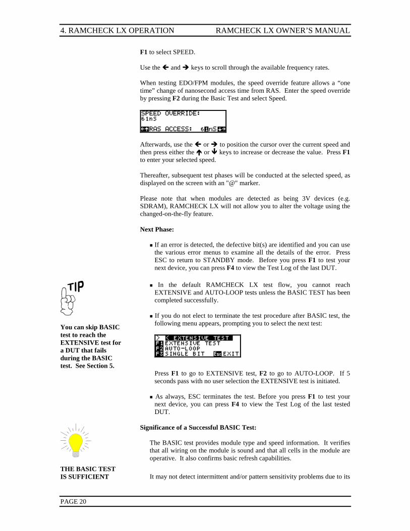
If an error is detected, the defective bit(s) are identified and you can use
the various error menus to examine all the details of the error. Press ESC to return to STANDBY mode. Before you press F1 to test your next device, you can press F4 to view the Test Log of the last DUT.
You can skip BASIC test to reach the EXTENSIVE test for a DUT that fails during the BASIC test. See Section 5.
In the default RAMCHECK LX test flow, you cannot reach EXTENSIVE and AUTO-LOOP tests unless the BASIC TEST has been completed successfully.
If you do not elect to terminate the test procedure after BASIC test, the
following menu appears, prompting you to select the next test:
Press F1 to go to EXTENSIVE test, F2 to go to AUTO-LOOP. If 5 seconds pass with no user selection the EXTENSIVE test is initiated.
As always, ESC terminates the test. Before you press F1 to test your next device, you can press F4 to view the Test Log of the last tested DUT.
Significance of a Successful BASIC Test: The BASIC test provides module type and speed information. It verifies that all wiring on the module is sound and that all cells in the module are operative. It also confirms basic refresh capabilities.
THE BASIC TEST IS SUFFICIENT
It may not detect intermittent and/or pattern sensitivity problems due to its
RAMCHECK LX OWNER’S MANUAL 4. RAMCHECK LX OPERATION
PAGE 21
FOR MOST SCREENING TESTS. Most defective modules will be detected during this test.
short execution time.
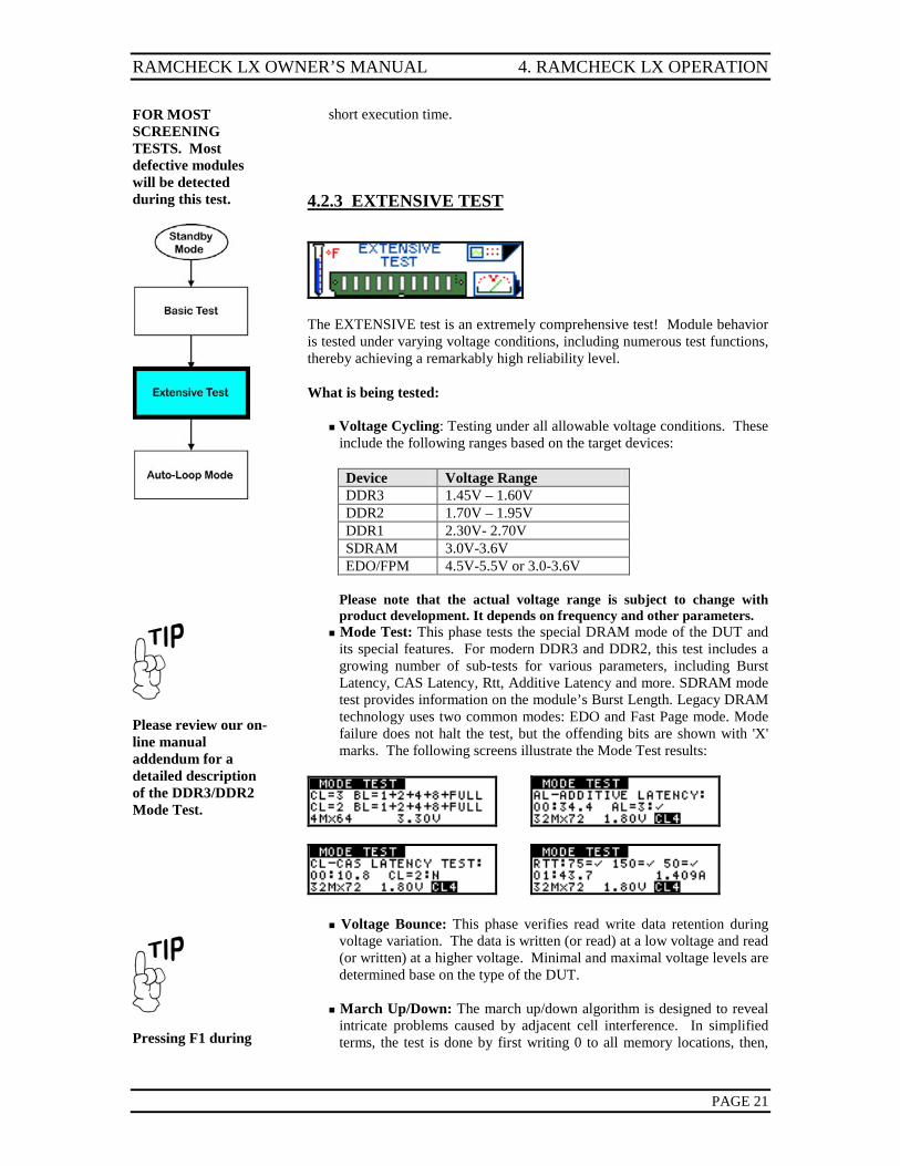
4.2.3 EXTENSIVE TEST
The EXTENSIVE test is an extremely comprehensive test! Module behavior is tested under varying voltage conditions, including numerous test functions, thereby achieving a remarkably high reliability level. What is being tested:
Voltage Cycling: Testing under all allowable voltage conditions. These include the following ranges based on the target devices:
Device Voltage Range DDR3 1.45V – 1.60V DDR2 1.70V – 1.95V DDR1 2.30V- 2.70V SDRAM 3.0V-3.6V EDO/FPM 4.5V-5.5V or 3.0-3.6V
Please note that the actual voltage range is subject to change with
product development. It depends on frequency and other parameters.
Please review our on-line manual addendum for a detailed description of the DDR3/DDR2 Mode Test.
Pressing F1 during
Mode Test: This phase tests the special DRAM mode of the DUT and its special features. For modern DDR3 and DDR2, this test includes a growing number of sub-tests for various parameters, including Burst Latency, CAS Latency, Rtt, Additive Latency and more. SDRAM mode test provides information on the module’s Burst Length. Legacy DRAM technology uses two common modes: EDO and Fast Page mode. Mode failure does not halt the test, but the offending bits are shown with 'X' marks. The following screens illustrate the Mode Test results:
Voltage Bounce: This phase verifies read write data retention during
voltage variation. The data is written (or read) at a low voltage and read (or written) at a higher voltage. Minimal and maximal voltage levels are determined base on the type of the DUT.
March Up/Down: The march up/down algorithm is designed to reveal
intricate problems caused by adjacent cell interference. In simplified terms, the test is done by first writing 0 to all memory locations, then,
4. RAMCHECK LX OPERATION RAMCHECK LX OWNER’S MANUAL
PAGE 22
the EXTENSIVE test terminates the current step and proceeds to the next one (within the EXTENSIVE test).
while scanning from first address to last address, the test verifies that a 0 remains in each location, then it is replaced with a 1. After the entire memory address is “marched up” in this fashion, the process reverses itself to perform the “march down” test. This time while scanning from the last address to the first address, the test verifies that a 1 remains in each location and then replaces it with a 0.
Relative Refresh and Relatively Spikes are used only for legacy EDO/FPM devices.
Relative Refresh/cell leakage: This test provides a relative value for the ability of the memory chip to retain data between refresh cycles. "Relative" means that the result is not an absolute time value but a comparative one. Relative relation between values is exponential. For example: A DUT with a relative value of "5" retained data integrity twice as long as one with a value of "4" without requiring refresh. Typical good values are 3 and higher. Since this test is of the Out-of-Specification type, lower results do not imply that a module is defective, as it can still work within its published specifications!
Relative Voltage Spikes Performance: This test provides a relative
value that indicates how well a module can sustain voltage spikes before a data loss occurs. Relative relations here are not exponential. Typical good values are 3 and above. Since this test is of the Out-of-Specification type, lower results do not imply that a module is defective, as it can still work within its published specifications!
As you watch the red Module Power LED during the Relative Voltage Spikes test, you will see that it flashes vigorously. This LED is directly connected to the module's power supply. RAMCHECK LX creates artificial voltage spikes (of 5V to 1.5V or to 6.0V) after loading a complete test pattern. Memory devices with higher Relative Voltage Spikes figures can withstand more spikes in an actual application. Take into account that modules with larger built-in capacitors normally exhibit higher Relative Voltage Spikes figures due to the capacitors' smoothing effect on the spikes. Some complex modules, which utilize PAL chips and/or logic chips, may exhibit significantly lower Relative Voltage Spikes figures. Note that ALL relative tests are absolutely safe, as RAMCHECK LX DOES NOT exceed any allowable voltage/current rating!
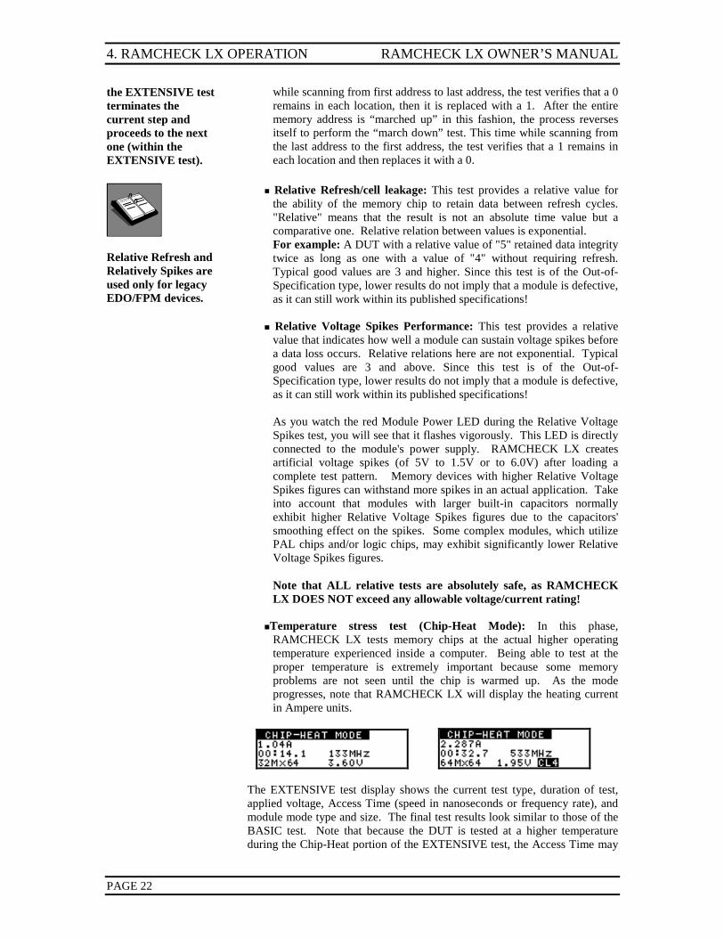
Temperature stress test (Chip-Heat Mode): In this phase,
RAMCHECK LX tests memory chips at the actual higher operating temperature experienced inside a computer. Being able to test at the proper temperature is extremely important because some memory problems are not seen until the chip is warmed up. As the mode progresses, note that RAMCHECK LX will display the heating current in Ampere units.
The EXTENSIVE test display shows the current test type, duration of test, applied voltage, Access Time (speed in nanoseconds or frequency rate), and module mode type and size. The final test results look similar to those of the BASIC test. Note that because the DUT is tested at a higher temperature during the Chip-Heat portion of the EXTENSIVE test, the Access Time may
RAMCHECK LX OWNER’S MANUAL 4. RAMCHECK LX OPERATION
PAGE 23
be slower than the value obtained with the BASIC test. Next Phase:
If an error is detected during the EXTENSIVE test, the defective bit(s)
are identified and the display waits for your acknowledgment. Press ESC after review to return to Standby Mode.
If no errors are detected - an OK test result is shown and you are
prompted to continue. Press F1 to go to AUTO-LOOP for burn-in and pattern tests. If the time delay passes with no user selection, the AUTO-LOOP test is initiated.
As always, ESC terminates the test. Before you press F1 to test your
next device, you can press F4 to view the Test Log of the last tested DUT. The Test Log provides you with a detailed list of all the test results, including speed drift information.
Significance of a Successful EXTENSIVE Test:
The EXTENSIVE test verifies proper module operation under varying voltage conditions. It will detect intermittent problems which are either temperature dependent or resulting from adjacent cell interference. It provides comparative scores of module performance. It further tests the module with additional data patterns besides those utilized by the BASIC test.
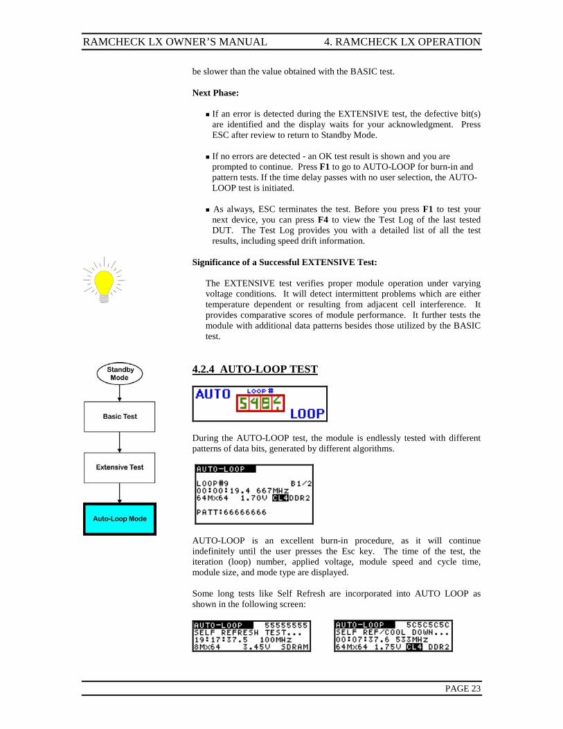
4.2.4 AUTO-LOOP TEST
During the AUTO-LOOP test, the module is endlessly tested with different patterns of data bits, generated by different algorithms.
AUTO-LOOP is an excellent burn-in procedure, as it will continue indefinitely until the user presses the Esc key. The time of the test, the iteration (loop) number, applied voltage, module speed and cycle time, module size, and mode type are displayed. Some long tests like Self Refresh are incorporated into AUTO LOOP as shown in the following screen:
4. RAMCHECK LX OPERATION RAMCHECK LX OWNER’S MANUAL
PAGE 24
A recommended Calibration & Upgrade procedure is available from the factory. Refer to Appendix H in the enclosed CD for details.
Next Phase: The AUTO-LOOP test terminates when an error is detected or
in response to the user's command. If an error is detected, the defective bit(s) are identified and the display
waits for your acknowledgment. If no error is detected, the test will continue indefinitely; or until ESC is
pressed to terminate the test. As the tester and module may get hot, make sure the test area is well ventilated (see Safety Precautions).
As always, ESC terminates the test. Before you press F1 to test your
next device, you can press F4 to view the Test Log of the last tested DUT. The Test Log provides you with a detailed list of all the test results, including speed drift information.
Significance of a Successful AUTO-LOOP Test:
AUTO-LOOP is designed to detect pattern sensitivity problems, as it tests the modules under many different patterns. 20 minutes or more are sufficient to detect most pattern sensitivity problems.
Notice that the AUTO-LOOP mode makes RAMCHECK LX an excellent instrument for continuous burn-in procedure.
RAMCHECK LX OWNER’S MANUAL 5. ADVANCED TESTS
PAGE 25
5. ADVANCED TESTS RAMCHECK LX advanced tests are essentially made by changing the setup.
While most casual and non-technical users may not need to use RAMCHECK LX’s setup feature, you can get the most from your unit by reviewing the material presented in this section.
RAMCHECK LX has a built-in EEPROM device which stores your setup. Therefore, when you turn your RAMCHECK LX on, the unit “remembers” its last setup.
5.1 ADVANCED SETUP OVERVIEW
RAMCHECK LX Advanced Setup mode lets you do the following:
Preset a fixed speed (RAS access time or SDRAM Frequency Rate) reference so that all memory slower than the reference will be failed. This is different than the default mode, which automatically displays the actual speed.
Preset a fixed refresh value for modules that you wish to have tested at
various refresh rates. Preset a fixed module (or chip) size so that all tested memory will fail if it is
not of this type (as opposed to the default mode which automatically detects the module size).
Customize the Test Flow by selectively skipping various test modes and
phases. Change the values of the Row Address Hold Time and the RAS to CAS
delay time. Take an in-depth look at the operation of the automatic Access Time
algorithm [performance]. Repair bad modules faster.
Press any key (except ESC) if you wish to skip the SETUP initial graphic screen.
5.2 ACCESSING SETUP MODE
You can enter the RAMCHECK LX’s Advanced SETUP mode only from the STANDBY mode by first pressing F2. The setup graphic screen will appear momentarily. Thereafter, the menu offers four selections:
F1 SETUP PARAMETERS F2 TESTFLOW F3 LIST SETUP F4 AUTO (RAMCHECK LX DEFAULT)
Selecting the next menu (F5) provide more selections:
F1 CONFIGURATION F2 SPD Support F3 Product Information
5. ADVANCED TESTS RAMCHECK LX OWNER’S MANUAL
PAGE 26
These selections are detailed below. You return to the STANDBY mode by pressing ESC. If the current setup was changed, you will see a message notifying you that the new setup is stored in RAMCHECK LX’s non-volatile memory.
5.3 SETUP PARAMETERS
The SETUP PARAMETERS section, in which users can preset the type, frequency, size, speed, and other parameters of the tested modules or chips, is one of the more powerful features which will appeal to advanced users. Presetting the frequency rate of the module allows you to test
DDR3/DDR2/DDR1/SDRAM memory operation at a fixed reference. For example, with a preset value of 533MHz, RAMCHECK LX will fail all modules operating at slower frequency rates.
Presetting the EDO/FPM RAS Access Time allows you to test memory
operation at a fixed reference. For example, with a preset value of 47nS, RAMCHECK LX will fail all modules slower than 47nS, even if they operate fine at a slower speed.
The importance of presetting size may not be immediately apparent. The
following example will illustrate a potential use. Suppose that you are testing a batch of 8Mx72 modules which accidentally includes one 4Mx64 module. Without the ability to preset size, you have to closely watch RAMCHECK LX’s automatic size indication in order to catch this 4Mx64 module. With a preset size of 8Mx72, RAMCHECK LX aborts the tests and responds with an error message (SIZE ERROR: 4Mx64 NOT EQUAL TO @8Mx72) when it detects a module other than 8Mx72.
Selecting F4 on this and most other setup menus will set the current setup group to their default (AUTO) values.
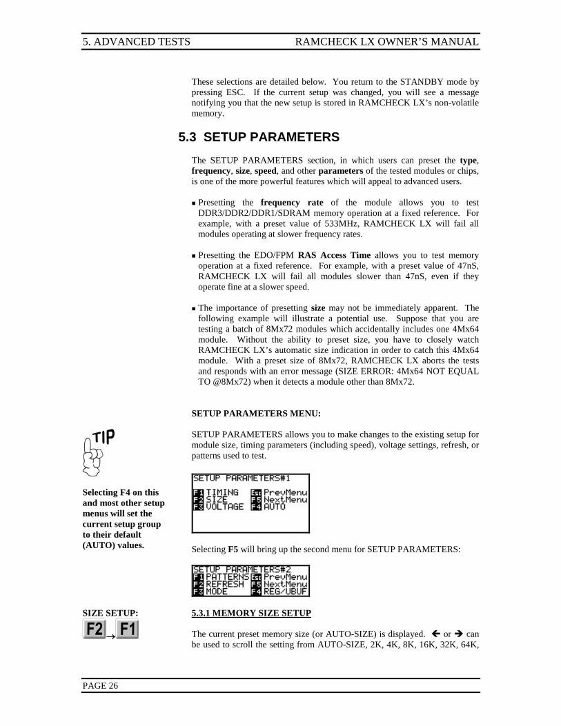
SETUP PARAMETERS MENU: SETUP PARAMETERS allows you to make changes to the existing setup for module size, timing parameters (including speed), voltage settings, refresh, or patterns used to test.
Selecting F5 will bring up the second menu for SETUP PARAMETERS:
SIZE SETUP:
→
5.3.1 MEMORY SIZE SETUP
The current preset memory size (or AUTO-SIZE) is displayed. or can be used to scroll the setting from AUTO-SIZE, 2K, 4K, 8K, 16K, 32K, 64K,
RAMCHECK LX OWNER’S MANUAL 5. ADVANCED TESTS
PAGE 27
→
The RAMCHECK LX screen has eight lines of text but only four lines may be shown to save space.
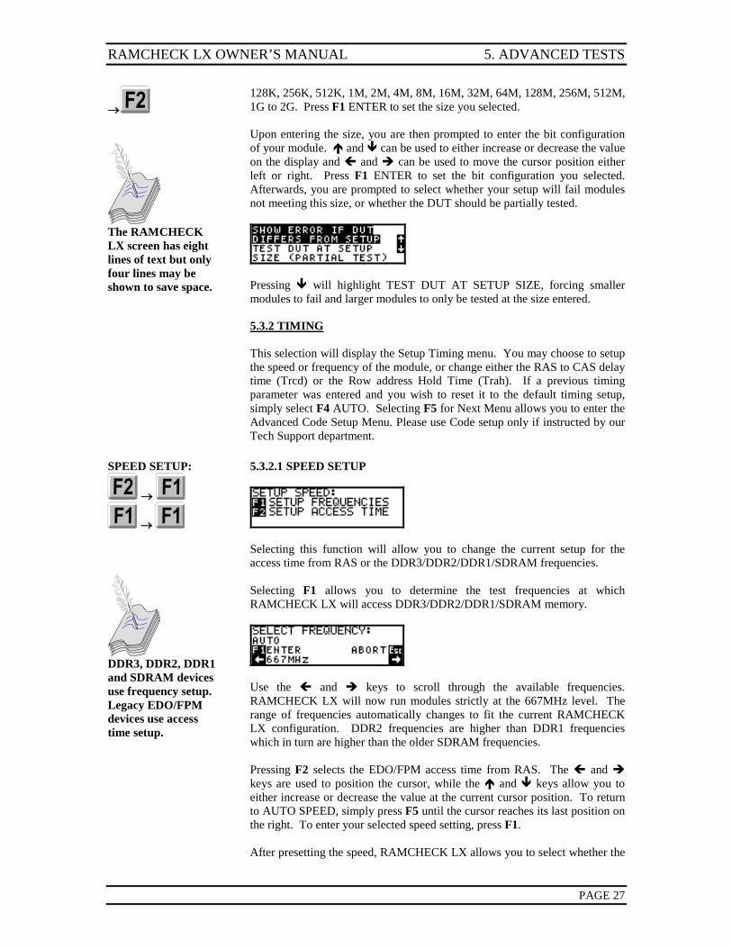
128K, 256K, 512K, 1M, 2M, 4M, 8M, 16M, 32M, 64M, 128M, 256M, 512M, 1G to 2G. Press F1 ENTER to set the size you selected. Upon entering the size, you are then prompted to enter the bit configuration of your module. and can be used to either increase or decrease the value on the display and and can be used to move the cursor position either left or right. Press F1 ENTER to set the bit configuration you selected. Afterwards, you are prompted to select whether your setup will fail modules not meeting this size, or whether the DUT should be partially tested.
Pressing will highlight TEST DUT AT SETUP SIZE, forcing smaller modules to fail and larger modules to only be tested at the size entered.
5.3.2 TIMING
This selection will display the Setup Timing menu. You may choose to setup the speed or frequency of the module, or change either the RAS to CAS delay time (Trcd) or the Row address Hold Time (Trah). If a previous timing parameter was entered and you wish to reset it to the default timing setup, simply select F4 AUTO. Selecting F5 for Next Menu allows you to enter the Advanced Code Setup Menu. Please use Code setup only if instructed by our Tech Support department.
SPEED SETUP:
→
→
DDR3, DDR2, DDR1 and SDRAM devices use frequency setup. Legacy EDO/FPM devices use access time setup.
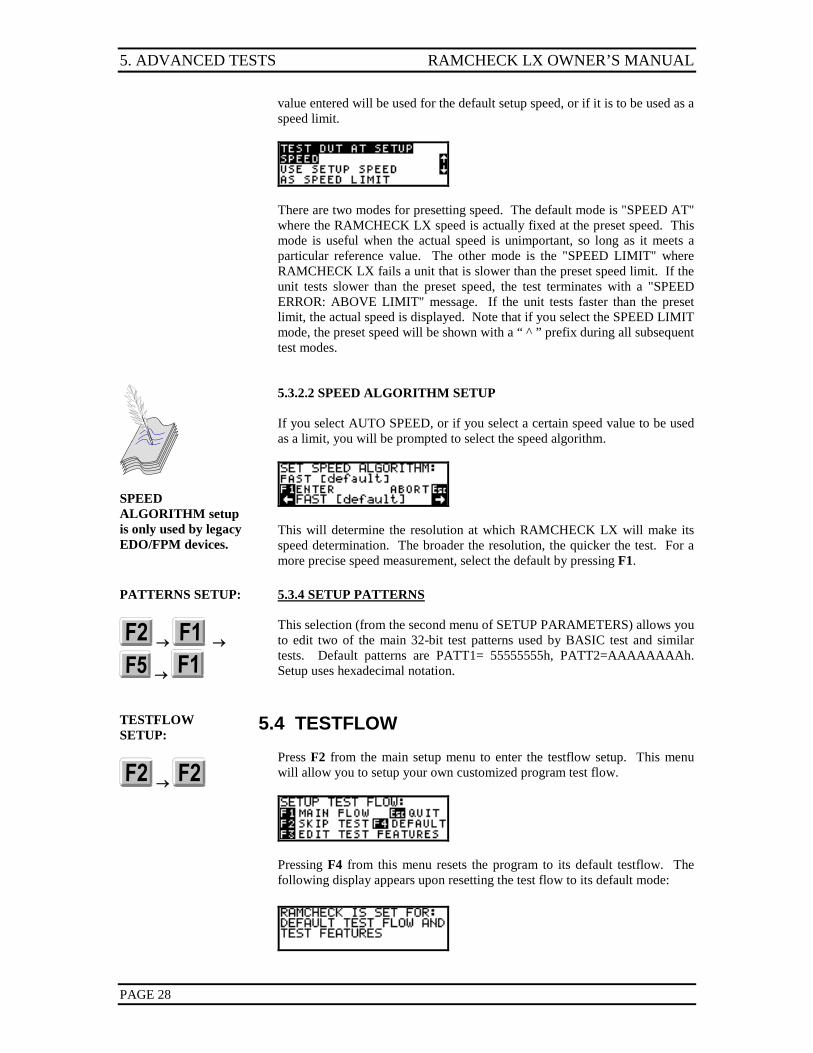
5.3.2.1 SPEED SETUP
Selecting this function will allow you to change the current setup for the access time from RAS or the DDR3/DDR2/DDR1/SDRAM frequencies. Selecting F1 allows you to determine the test frequencies at which RAMCHECK LX will access DDR3/DDR2/DDR1/SDRAM memory.
Use the and keys to scroll through the available frequencies. RAMCHECK LX will now run modules strictly at the 667MHz level. The range of frequencies automatically changes to fit the current RAMCHECK LX configuration. DDR2 frequencies are higher than DDR1 frequencies which in turn are higher than the older SDRAM frequencies. Pressing F2 selects the EDO/FPM access time from RAS. The and keys are used to position the cursor, while the and keys allow you to either increase or decrease the value at the current cursor position. To return to AUTO SPEED, simply press F5 until the cursor reaches its last position on the right. To enter your selected speed setting, press F1. After presetting the speed, RAMCHECK LX allows you to select whether the
5. ADVANCED TESTS RAMCHECK LX OWNER’S MANUAL
PAGE 28
value entered will be used for the default setup speed, or if it is to be used as a speed limit.
There are two modes for presetting speed. The default mode is "SPEED AT" where the RAMCHECK LX speed is actually fixed at the preset speed. This mode is useful when the actual speed is unimportant, so long as it meets a particular reference value. The other mode is the "SPEED LIMIT" where RAMCHECK LX fails a unit that is slower than the preset speed limit. If the unit tests slower than the preset speed, the test terminates with a "SPEED ERROR: ABOVE LIMIT" message. If the unit tests faster than the preset limit, the actual speed is displayed. Note that if you select the SPEED LIMIT mode, the preset speed will be shown with a “ ^ ” prefix during all subsequent test modes.
SPEED ALGORITHM setup is only used by legacy EDO/FPM devices.
5.3.2.2 SPEED ALGORITHM SETUP If you select AUTO SPEED, or if you select a certain speed value to be used as a limit, you will be prompted to select the speed algorithm.
This will determine the resolution at which RAMCHECK LX will make its speed determination. The broader the resolution, the quicker the test. For a more precise speed measurement, select the default by pressing F1.
PATTERNS SETUP:
→ →
→
5.3.4 SETUP PATTERNS
This selection (from the second menu of SETUP PARAMETERS) allows you to edit two of the main 32-bit test patterns used by BASIC test and similar tests. Default patterns are PATT1= 55555555h, PATT2=AAAAAAAAh. Setup uses hexadecimal notation.
TESTFLOW SETUP:
→
5.4 TESTFLOW
Press F2 from the main setup menu to enter the testflow setup. This menu will allow you to setup your own customized program test flow.
Pressing F4 from this menu resets the program to its default testflow. The following display appears upon resetting the test flow to its default mode:
RAMCHECK LX OWNER’S MANUAL 5. ADVANCED TESTS
PAGE 29
SKIP TESTS:
→ →
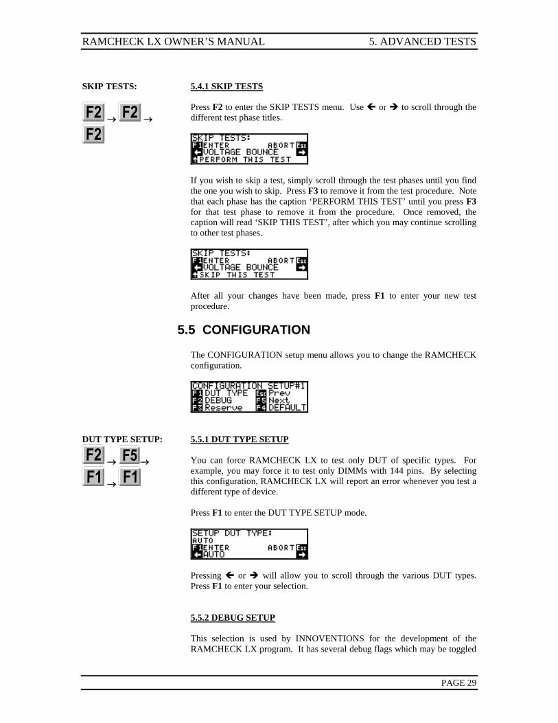
5.4.1 SKIP TESTS
Press F2 to enter the SKIP TESTS menu. Use or to scroll through the different test phase titles.
If you wish to skip a test, simply scroll through the test phases until you find the one you wish to skip. Press F3 to remove it from the test procedure. Note that each phase has the caption ‘PERFORM THIS TEST’ until you press F3 for that test phase to remove it from the procedure. Once removed, the caption will read ‘SKIP THIS TEST’, after which you may continue scrolling to other test phases.
After all your changes have been made, press F1 to enter your new test procedure.
5.5 CONFIGURATION
The CONFIGURATION setup menu allows you to change the RAMCHECK configuration.
DUT TYPE SETUP:
→ →
→
5.5.1 DUT TYPE SETUP
You can force RAMCHECK LX to test only DUT of specific types. For example, you may force it to test only DIMMs with 144 pins. By selecting this configuration, RAMCHECK LX will report an error whenever you test a different type of device. Press F1 to enter the DUT TYPE SETUP mode.
Pressing or will allow you to scroll through the various DUT types. Press F1 to enter your selection.
5.5.2 DEBUG SETUP
This selection is used by INNOVENTIONS for the development of the RAMCHECK LX program. It has several debug flags which may be toggled
5. ADVANCED TESTS RAMCHECK LX OWNER’S MANUAL
PAGE 30
by their corresponding keys. Pressing F4 from the configuration menu will reset the configuration to its default settings.
VIEW PRODUCT INFORMATION:
→ →
Additional selections in the Configuration menu are discussed in the CD companion.
5.5.3 PRODUCT INFORMATION DISPLAY
Selecting F3 from the second main SETUP Menu allows you to view the Product Information Display. This display summarizes the features of your unit as well as recent calibration information. It is often critical for our Tech Support department to have this information when you encounter a problem or require a major upgrade. Once you review this Product Information on RAMCHECK LX, make sure it is connected to your PC. First open the Realtime Interface (See Section 6), and then press F2 on the RAMCHECK LX. This will copy the information from the RAMCHECK LX screen into the Test Log on your PC. The PC Test Log can be saved and email to our Tech Support.
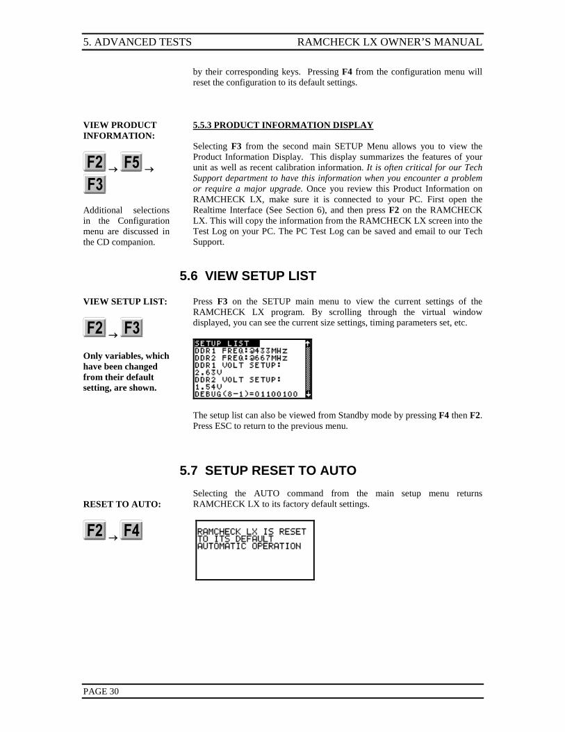
5.6 VIEW SETUP LIST
VIEW SETUP LIST:
→ Only variables, which have been changed from their default setting, are shown.
Press F3 on the SETUP main menu to view the current settings of the RAMCHECK LX program. By scrolling through the virtual window displayed, you can see the current size settings, timing parameters set, etc.
The setup list can also be viewed from Standby mode by pressing F4 then F2. Press ESC to return to the previous menu.
5.7 SETUP RESET TO AUTO
RESET TO AUTO:
→
Selecting the AUTO command from the main setup menu returns RAMCHECK LX to its factory default settings.
RAMCHECK LX OWNER’S MANUAL 6. PC PROGRAMS
PAGE 31
6. PC PROGRAM You must register your RAMCHECK LX to obtain the password for firmware download.
This program requires Windows 2000/XP/VISTA. Your PC must have USB port.
While RAMCHECK LX is a stand-alone unit, the product includes the RAMCHECK LX PC Communications program which allows you to upgrade your RAMCHECK LX’s flash EPROM with the latest firmware available at our website (www.innoventions.com). This software also provides you with all the essential communication functions you will need to operate the RAMCHECK LX via your PC:
The capability to download updated firmware files from our FTP server onto the RAMCHECK LX Flash memory.
A Realtime interface between RAMCHECK LX and the PC so that you can
control RAMCHECK LX from your PC and also view, save, and print test results from the Test Log.
SPD support for editing, saving, and programming of the SPD chip on your
tested memory devices. SPD support is for advanced users only. It is extensively described in the PC Communications program On-Line Help, as well as on our website.
Setup support for RAMCHECK LX. Graphics interface between RAMCHECK LX’s screen to your PC display. Extensive On-Line Help and Tutorials.
You can download the latest version of this PC Communications program from our website.
Installation Problems? Please review the detailed RAMCHECK LX Installation Addendum at our web site.
HARD DISK INSTALLATION: Insert the enclosed CD Companion into your CD ROM drive. Please DO NOT CONNECT the RAMCHECK LX until installation is completed. The automatic program launcher will start and provide you with a menu of installation options. If the program launcher does not start automatically, you can run the “setup.exe” file in your CD ROM drive. Choosing Default Installation places the PC Communications program in a “program files/innoventions/ramcheck lx” directory. The installation creates a shortcut icon on your desktop as well as an UNINSTALL utility. Selecting the Advanced Installation allows you to override the installation directory. Please note that the automatic USB driver installer (by FTDI, Inc. www.ftdichip.com) uses a command line process which does not require user's intervention. Depending on your current setup, the program can take up to few minutes to complete. Copies of the drivers are available in the USB directory of the CD or at the FTDI web site: http://www.ftdichip.com/Drivers/D2XX.htm
6. PC PROGRAMS RAMCHECK LX OWNER’S MANUAL
PAGE 32
Press the USB Status button to activate the USB connection.
VERIFYING THE USB CONNECTION: Use the enclosed USB cable to connect the RAMCHECK LX to an available USB port on your PC. Turn on the RAMCHECK LX and then activate the PC Communications program. You can now verify the USB connection by pressing the find RAMCHECK LX button on the PC program. You may need to press the USB Status button if it is not showing ‘ON’.
You must verify the USB connection by pressing the FIND RAMCHECK LX button on the PC program.
6.1 RAMCHECK LX DOWNLOADER
The RAMCHECK LX Downloader portion of the PC Programs is the key utility for performing a RAMCHECK LX FLASH upgrade. We recommend that you review RAMCHECK LX development log on our Web site, which outlines the latest changes and added features of the new RAMCHECK LX firmware. Use the FIND RAMCHECK LX button on your PC Communication program to verify the USB connection before you start a firmware upgrade. Please press the USB Status button if it shows ‘OFF’.
You may also click on
to activate the automatic firmware upgrade process.
See Section 6.1.2 to review the manual firmware upgrade function.
6.1.1 AUTOMATIC FIRMWARE UPGRADE
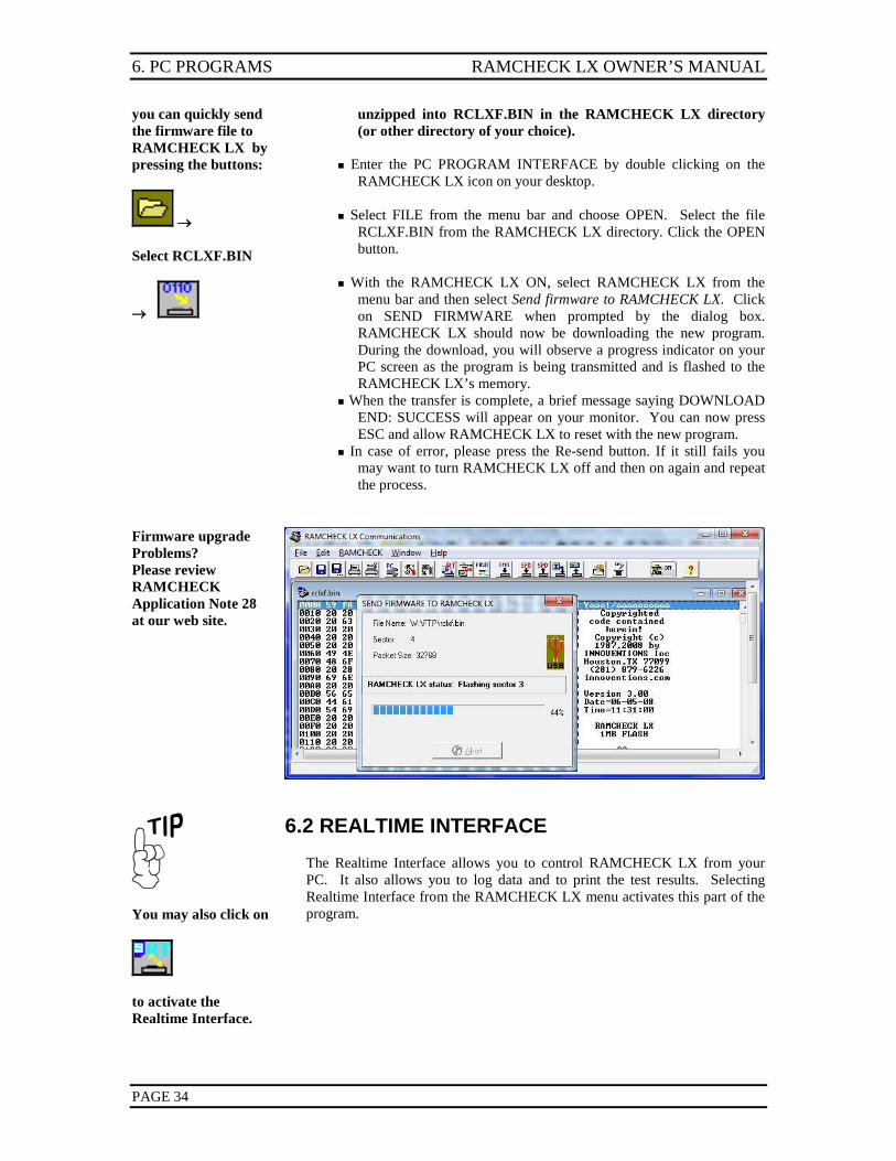
The automated firmware upgrade process is the preferred method to upgrade your RAMCHECK LX. You must first register your RAMCHECK LX at www.innoventions.com to obtain your password. The password will be e-mailed to you instantly. Use the User Information page of the Software Setup menu to enter your e-mail (userId) and password. From the RAMCHECK LX menu, select Automatic Firmware Upgrade. It first connects to INNOVENTIONS' FTP server and downloads the "rclxf.zip" file to the RAMCHECK LX program directory. It then unzips the "rclxf.zip" into a new "rclxf.bin" firmware file (after backing up any existing firmware file with the same name to "rclxf.bak"). Finally, it activates the firmware Downloader program and prompts you to upgrade your RAMCHECK LX. Selecting SEND FIRMWARE will then begin your upgrade. The following window appears when you activate the automatic upgrade:
RAMCHECK LX OWNER’S MANUAL 6. PC PROGRAMS
PAGE 33
If your computer has direct internet connection, please make sure it is activated and simply start the process by clicking the Connect button. Please note that you may need to wait while the process works. The FTP connection dialog box shows your e-mail (as registered) in the UserID and the password obtained during registration (if you have completed the Software Setup section). The status portion of the FTP connection dialog box shows the progress of the download. At the successful end of the download process from the FTP server, the firmware Downloader is activated, prompting you to send the new firmware to RAMCHECK LX. Click ‘SEND FIRMWARE’. After a successful download, RAMCHECK LX must be reset (by pressing ESC) in order to start with the new firmware. While the process is automatic, it allows you to abort at various key points. If you abort during the FTP download, your older "rclxf.bin" firmware file remains intact. If you abort the firmware Downloader program, your RAMCHECK LX will not be upgraded, but the firmware file "rclxf.bin" will be updated. Please note that this process replaces your previous firmware file and keeps only one backup as "rclxf.bak". You may want to keep previous hardware versions by renaming them "rclxf_302.bin" or "rclxf_310.bin (for versions 3.02 and 3.10 respectively).
Be sure to check for upgrades every few months to insure the best results from your RAMCHECK LX investment.
6.1.2 MANUALLY UPGRADING THE FIRMWARE
If you do not have a direct connection to the Internet, or you can only access our web site from a remote computer, you may elect to upgrade your tester manually by first acquiring the firmware file online, then downloading it to RAMCHECK LX using the RAMCHECK LX Downloader. The Downloader portion of the RAMCHECK LX Communications program sends a variety of file data to RAMCHECK LX, including Firmware files. FIRMWARE FILES Upgrading RAMCHECK LX is accomplished by following the procedure outlined below:
Once downloaded,
The RCLXF.BIN file is the current RAMCHECK LX firmware, which you must download from our Web Site to your computer. You download the compressed RCLXF.ZIP file which must be
6. PC PROGRAMS RAMCHECK LX OWNER’S MANUAL
PAGE 34
you can quickly send the firmware file to RAMCHECK LX by pressing the buttons:
→ Select RCLXF.BIN
→
unzipped into RCLXF.BIN in the RAMCHECK LX directory (or other directory of your choice).
Enter the PC PROGRAM INTERFACE by double clicking on the
RAMCHECK LX icon on your desktop. Select FILE from the menu bar and choose OPEN. Select the file
RCLXF.BIN from the RAMCHECK LX directory. Click the OPEN button.
With the RAMCHECK LX ON, select RAMCHECK LX from the
menu bar and then select Send firmware to RAMCHECK LX. Click on SEND FIRMWARE when prompted by the dialog box. RAMCHECK LX should now be downloading the new program. During the download, you will observe a progress indicator on your PC screen as the program is being transmitted and is flashed to the RAMCHECK LX’s memory.
When the transfer is complete, a brief message saying DOWNLOAD END: SUCCESS will appear on your monitor. You can now press ESC and allow RAMCHECK LX to reset with the new program.
In case of error, please press the Re-send button. If it still fails you may want to turn RAMCHECK LX off and then on again and repeat the process.
Firmware upgrade Problems? Please review RAMCHECK Application Note 28 at our web site.
You may also click on
to activate the Realtime Interface.
6.2 REALTIME INTERFACE The Realtime Interface allows you to control RAMCHECK LX from your PC. It also allows you to log data and to print the test results. Selecting Realtime Interface from the RAMCHECK LX menu activates this part of the program.
RAMCHECK LX OWNER’S MANUAL 6. PC PROGRAMS
PAGE 35
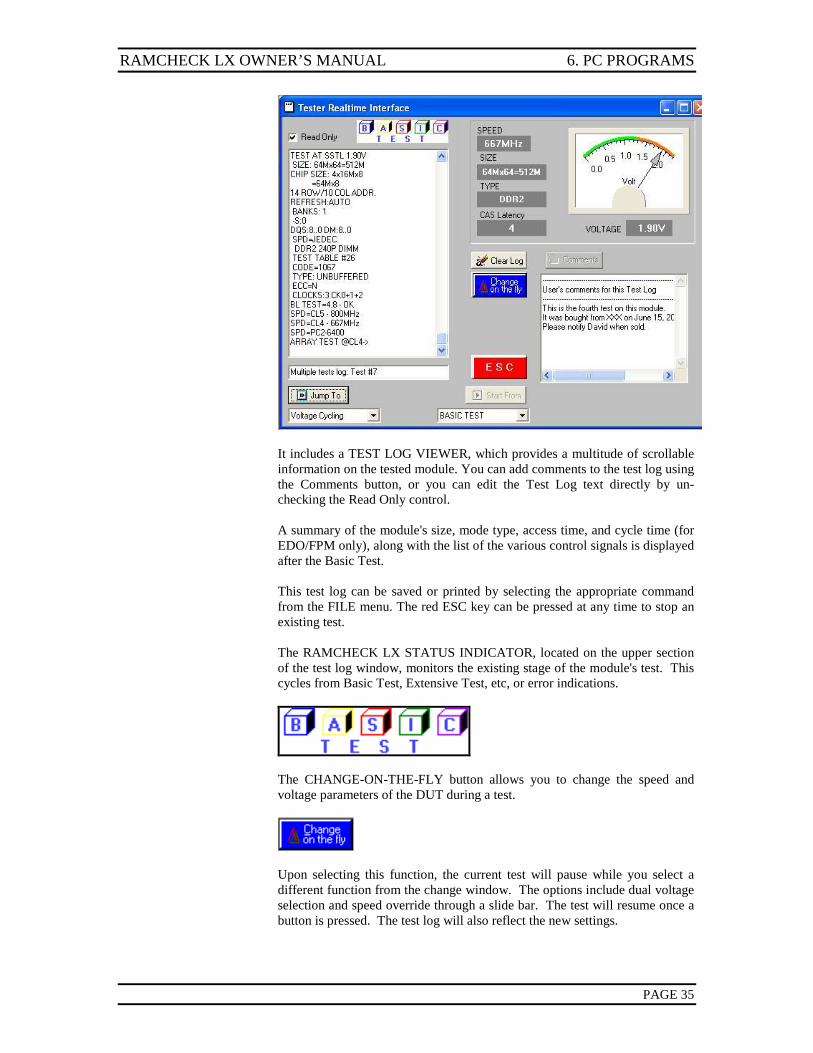
It includes a TEST LOG VIEWER, which provides a multitude of scrollable information on the tested module. You can add comments to the test log using the Comments button, or you can edit the Test Log text directly by un-checking the Read Only control. A summary of the module's size, mode type, access time, and cycle time (for EDO/FPM only), along with the list of the various control signals is displayed after the Basic Test. This test log can be saved or printed by selecting the appropriate command from the FILE menu. The red ESC key can be pressed at any time to stop an existing test. The RAMCHECK LX STATUS INDICATOR, located on the upper section of the test log window, monitors the existing stage of the module's test. This cycles from Basic Test, Extensive Test, etc, or error indications.
The CHANGE-ON-THE-FLY button allows you to change the speed and voltage parameters of the DUT during a test.
Upon selecting this function, the current test will pause while you select a different function from the change window. The options include dual voltage selection and speed override through a slide bar. The test will resume once a button is pressed. The test log will also reflect the new settings.
6. PC PROGRAMS RAMCHECK LX OWNER’S MANUAL
PAGE 36
You may also select
to enter setup mode, and press
to send setup data to RAMCHECK LX.
See Section 5 to learn more about RAMCHECK LX Setup.
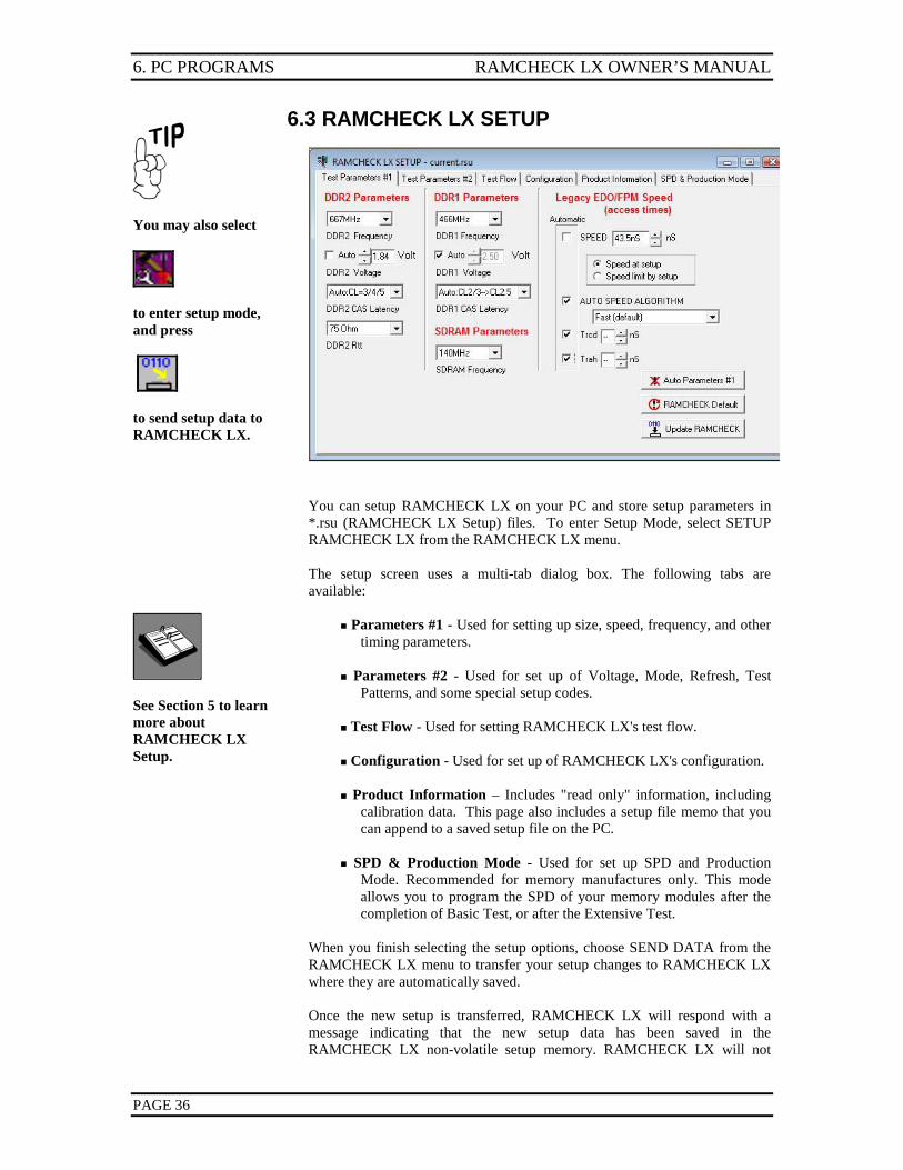
6.3 RAMCHECK LX SETUP
You can setup RAMCHECK LX on your PC and store setup parameters in *.rsu (RAMCHECK LX Setup) files. To enter Setup Mode, select SETUP RAMCHECK LX from the RAMCHECK LX menu. The setup screen uses a multi-tab dialog box. The following tabs are available:
Parameters #1 - Used for setting up size, speed, frequency, and other timing parameters.
Parameters #2 - Used for set up of Voltage, Mode, Refresh, Test
Patterns, and some special setup codes. Test Flow - Used for setting RAMCHECK LX's test flow. Configuration - Used for set up of RAMCHECK LX's configuration. Product Information – Includes "read only" information, including
calibration data. This page also includes a setup file memo that you can append to a saved setup file on the PC.
SPD & Production Mode - Used for set up SPD and Production
Mode. Recommended for memory manufactures only. This mode allows you to program the SPD of your memory modules after the completion of Basic Test, or after the Extensive Test.
When you finish selecting the setup options, choose SEND DATA from the RAMCHECK LX menu to transfer your setup changes to RAMCHECK LX where they are automatically saved. Once the new setup is transferred, RAMCHECK LX will respond with a message indicating that the new setup data has been saved in the RAMCHECK LX non-volatile setup memory. RAMCHECK LX will not
RAMCHECK LX OWNER’S MANUAL 6. PC PROGRAMS
PAGE 37
You may also select
to activate the Program Setup.
save unchanged setup data. PC PROGRAM SETUP Selecting the Setup Software item in the RAMCHECK LX menu allows you to setup the PC program. The minimum setup you must do is to enter your Password and UserId (your e-mail as registered) in the User Information page. This entry is required for the important firmware upgrade. You can also enter your company name to label the software printouts. Any change in the PC Program Setup menu is automatically saved on your PC.
6.4 RAMCHECK LX DIAGNOSTICS The RAMCHECK LX’s diagnostic program is used by INNOVENTIONS Tech Support. Special instructions will be given if we need you to use it to resolve a specific problem.
RAMCHECK LX OWNER’S MANUAL INDEX
PAGE 39
8.1. APPENDIX LIST APPENDIX A: SOFTWARE LICENSE AGREEMENT
Covers the standard user agreement between the INNOVENTIONS and you the purchaser. APPENDIX B: RAMCHECK LX TEST ALGORITHMS Discusses the use of RAMCHECK LX’s algorithms in modern memory devices. APPENDIX C: SDRAM TIMING AND PC-100/133 COMPLIANCE
Discusses the issues and parameters used to determine compliance between the available SDRAM standards.
APPENDIX D: EDO/FPM TIMING MEASUREMENTS Discusses the timing measurements as interpreted by RAMCHECK LX. APPENDIX E: MODULE REPAIR WITH RAMCHECK LX Discusses the capabilities of RAMCHECK LX that help identify defective components. APPENDIX F: MEMORY MODULE TECHNICAL REVIEW Discusses how the modern DIMM module came to exist. APPENDIX G: SPECIFICATIONS Provides product specifications for RAMCHECK LX. 8.2. MANUAL ADDENDA Updated on-line version of this RAMCHECK LX manual as well as important manual addenda for the DDR3, DDR2 and DDR1 adapters.
RAMCHECK LX OWNER’S MANUAL INDEX
PAGE 40
INDEX
A Access Time, 19, 22, 25, 27, 34
from clock, 17 RAS, 26, 27 speed, 25
adapters, 7 audible signals, 10, 11 AUTO-LOOP test, 8, 14, 20, 22, 23
B BASIC test, 8, 10, 14, 15, 17, 19, 20, 22, 23, 28 burn-in, 8, 24
C Change-on-the-fly, 19 Chip-Heat mode, 8, 22 Configuration Setup, 29 Cycle Time Measurement, 8
D DDR 100-pin Adapter, 37 DDR adapter, 4 DDR Chip Converter, 37 DDR PRO adapter, 37 DDR SODIMM Converter, 37 DDR1, 8, 16, 17, 18, 26 DDR2, 4, 8, 15, 16, 21, 26, 27, 37 DDR2 adapter, 4, 37 DDR2 SODIMM Adapter, 37 DDR2 SODIMM Converter, 37 DDR3, 4, 8, 15, 21, 26 DDR3 adapter, 4, 37 DEMO mode, 7 DIMM, 4, 14, 29 DIMMCHECK 100-pin, 37 DIMMCHECK 144-pin, 37 Direct Printer Interface, 37 DUT (Device Under Test), 8 DUT TYPE, 29
E EDO/FPM, 4, 8, 15, 17, 19, 22, 26 EOD/FPM SOJ Adapter, 37 error message, 15, 26 EXTENSIVE test, 8, 14, 20, 21, 22, 23
F Fast Page Mode, 8 FINAL TEST, 8 firmware, 2, 4, 10, 14, 31, 32
Firmware upgrade, 32 frequency, 4, 11, 15, 16, 19, 22, 26, 27, 35
G graphic display, 15 Group1 error, 18 Group2 error, 18
J JEDEC Translation, 17
K keyboard, 10, 11
L Legacy DRAM, 21
M Manual addendum
DDR2, 17, 21 MARCH UP/DOWN, 8 menus, 4, 10, 11, 12, 26, 28
configuration, 29 error display, 18, 20 graphic setup, 12 horizontal scroll, 12 pattern setup, 28 selection menu, 11 setup, 25, 26, 30 test flow, 28, 29 timing setup, 27 variable setup, 12 vertical scroll, 12
MODE Analysis, 8 Mode Test, 21 Module Insertion, 14 Module Removal, 14
P pattern sensitivity, 20, 24 PC PROGRAMS, 4, 31
RAMCHECK DIAGNOSTICS, 36 RAMCHECK Downloader, 32 RAMCHECK LX SETUP, 35 Realtime Interface, 34
PC-100/133 compliance, 38 power supply, 1, 7, 22 print test log, 34 Problem report form, 41 Product Information Display, 30 Production Mode, 35
RAMCHECK LX OWNER’S MANUAL INDEX
PAGE 41
R RAMCHECK, 4, 8, 15 RAMCHECK LX, 4 RAMCHECK LX DDR1, 4 RAMCHECK LX DDR2, 4, 37 RAMCHECK LX DDR2/DDR1, 37 RAMCHECK LX DDR3, 4, 37 RAMCHECK LX DDR3/DDR2, 37 RAMCHECK LX DDR3/DDR2/DDR1, 37 RAMCHECK LX Operation, 14 Registered, 8 Relative Refresh, 8, 22 Relative Voltage Spikes, 8, 22
S Safety precautions, 2 screen display, 10 SDRAM, 8, 15, 17, 21, 25, 26, 27 setup, 10, 14, 15, 25, 26, 27, 28, 29, 30 Setup List, 30 SIMCHECK, 2 SIMM Adapter, 7, 37 Skip tests, 29 SO DIMM 144 Adapter, 7 SO DIMM testing, 4, 37 sockets, 14 sockets, socket rating, 2, 14 SPD, 31, 35 speed. See Access time
SPEED LIMIT, 27 speed override, 19 STANDBY mode, 7, 13, 15, 18, 20, 25 structure information, 8 Sync Chip Adapter, 37
T Temperature stress test. See Chip-Heat mode Test accuracy, 3 test flow, 28 Test Log, 1, 13, 15, 18, 20, 22, 23 test results, 10, 22, 23 TEST SETUP mode, 25, 26 time delay, 22
U Unbuffered, 8 user interface, 10
V Voltage Bounce, 8, 21 Voltage Cycling, 8, 21
W warranty, 3 Web site, 37
Test Equipment Depot - 800.517.8431 - 99 Washington Street Melrose, MA 02176
TestEquipmentDepot.com


![Getting Started with the Multi-Standard …cache.freescale.com/files/dsp/doc/quick_ref_guide/...DSPA Ethernet DSPB Ethernet AMC Connector[P1] DDR2 Socket [P9] DDR1 Socket [P4] DSP](https://img.pdfslide.us/doc/110x75/5aeaade27f8b9ac3618e152a/getting-started-with-the-multi-standard-cache-ethernet-dspb-ethernet-amc-connectorp1.jpg)