Embed Size (px)
Citation preview

Raju Gautam Micro Co-generation of Heat and Power Hybrid with Renewables: State of the Art
Helsinki Metropolia University of Applied Sciences
Bachelor in Civil Engineering
Sustainable Building Engineering Thesis Date:23 May 2016

Abstract
Author Title Number of Pages Date
Raju Gautam Micro co-generation of heat and powerhybrid with Renewa-bles:State of the art. 32 pages 23 May 2016
Degree Bachelor in Engineering
Degree Programme Civil Engineering
Specialisation option Sustainable Building Engineering
Instructor Jorma Säteri, Principal Lecturer
The purpose of this bachelor’s thesis was to find out the possible options to construct a hybrid micro cogeneration of heat and power. This report analysed the available micro cogeneration heat and power technologies and possibilities to combine them with the renewable energy sources and clean energy technologies for the campus lab of Helsinki Metropolia University of Applied Sciences. The research mainly focused on the solar photovoltaic-thermal energy combined with the micro cogeneration technologies that use renewable and nearly clean energy sources like biomass and biogas and use the remote monitoring for the system. This thesis also tried to put some light on the hot topic in CHP: Fuel cell, which is still, at a research and development stage. The report focused on the integration of the existing micro CHP technologies and mainly solar energy. The report analysed the emission factors and energy savings from the use of CHP and renewable energy in residential building thus helping EU to meet the target set to achieve in 2020 (now pushed to 2030). Study of the report will give an overview of a movable hybrid micro cogeneration of heat and power and potential towards using in private and commercial sectors.
Keywords Micro CHP, hybrid, renewables, solar
0
Contents
1 Introduction 1
2 Existing Technologies 2
2.1 Fuel Cell Technology 2
2.2 Types of Existing Engines 4
3 Hybrid with renewables 6
3.1 Solar energy 6
3.2 Solar Technologies 7
3.2.1 Photovoltaic Technology 8
3.2.2 Solar thermal technology 8
4 Biomass micro CHP integrated with Photovoltaic Thermal Collector 10
5 Heat Pump with Photovoltaic panels integrated with Biogas micro CHP 12
6 Photovoltaic integrated Rainwater Fuel cell CHP 16
7 Case studies 19
7.1 Photovoltaic Thermal integrated Heat Pump 19
7.2 Solar CHP in Sweden 19
7.3 Mobile Biomass CHP 20
8 Environmental and Economic Performance Analysis 22
9 Conclusion 24
10 Reference 26

1
1 Introduction
The energy consumption of about 160 million buildings in Europe accounts for 40% of
total energy consumptions in Europe and the demand is mostly fulfilled by centralized
cogeneration of power and heat.36% of total carbon emissions in the European Union
is produced due to the centralized cogeneration of heat and power. For the production
of the heat and power, around 100 million litres of gas are used and 8 million gas boil-
ers are sold in Europe annually, which produce even more greenhouse gases. (1.)
Micro-cogeneration of heat and power (micro-CHP) means the generation of electricity
and heat for a residential building or small office buildings. The process includes the
production of thermal energy and electricity simultaneously. Since the heat is primary
product, the production of power is slightly more in micro cogeneration system than
when producing power primarily and using the excess heat for domestic hot water and
space heating purposes, as done in a large system. According to the EU legislation,
installations of micro cogeneration of units in the buildings should not have the output
more than 50 kW of electricity. With an ability to gain 85-90% efficiency, micro CHP
units can meet the demand of providing electricity and heat for space heating and do-
mestic hot water and reduce the greenhouse gas emissions and saves the energy
costs up to 25%. (2.)
Figure 1. Micro CHP system (3)
Figure 1 shows the production of electricity and heat energy in residential building us-
ing a micro CHP unit as well as the amount of energy produced and lost during the
process.

2
Centralized CHP is currently the most common option to provide heat and power to
buildings. However, it is necessary to reduce carbon emissions and save energy by
using renewables by 2030. Centralized CHP is good for densely populated areas but
the loss of heat and power during transmission is a major reason to change into micro
CHP. Decentralized cogeneration can be combined with the use of other clean source
of energy according to the availability and the affordability, such as wind and solar
energy thus helping to meet the target set by the European Commission.
The main objective of this study is to make an analysis of the available micro CHP
technologies and the renewable energy technologies so that a hybrid micro CHP sys-
tem can be constructed for the lab of Helsinki Metropolia University of Applied Scienc-
es. The report analysed few existing technologies that use almost clean fuel sources
and integrate them together with the renewable energy production.
2 Existing Technologies
There are five technologies of micro-CHP currently being used in the world. Four of
them use engine to drive a generator and produce energy while one relies on fuel cell
technology. (4.) Below, the existing technologies are briefly discussed.
2.1 Fuel Cell Technology
Fuel cell technology is at a trial phase in Europe. A fuel cell can be compared to a bat-
tery that generates electricity through an electrochemical reaction, as both batteries
and fuel cells convert chemical energy into electrical energy and produce heat. A fuel
cell uses an external supply of chemical energy and runs continuously unlike batteries,
which need to be recharged or discarded after a definite period of time. Generally, in a
fuel cell system an electrolyte is used as the fuel source. The electrolyte is then oxi-
dized which, releases electrons and electric current via an external circuit, that is, from
the anode to the cathode. (5.)
There are primarily two fuel cell technologies that are being used for micro combined
heat and power production. They are proton exchange membrane (PEM) and solid
oxide fuel cell (SOFC), however hydrogen fuel cell is also being developed. The solid
oxide fuel cells are high temperature fuel cells that operate in the range between 800

3
and 1000°C. The working principle is mostly the same as other fuel types. The differ-
ence is that the electrolyte is solid ceramic such as Zirconium oxide stabilised with
yttrium oxide. Oxygen is supplied at the cathode, and the ceramic electrolyte conducts
oxygen ions from the cathode to the anode while electrons go around the circuit pro-
ducing electricity. At the anode the oxygen ions combine with hydrogen to produce
water alongside heat and CO2. (6.)
Proton exchange membrane fuel cells (PEMFC) use an ion-conducting polymer as the
electrolyte. The electrolyte works at low temperatures, which allows for a fast start up.
In this system, hydrogen gas is ionized in the proton exchange membrane anode,
which releases electrons and protons. Protons are passed for the external circuit while
oxygen molecules are reduced in an acidic environment by electrons from the circuit at
the cathode. Protons pass through the PEM, from anode to cathode, which completes
the circuit.
Due to its smaller size, lighter weight and potential to provide high power densities,
PEM is a better option than other fuel cells as SOFC requires high temperatures to
operate. (7.)
Figure 2. Diagram for PEM FC (8)
Figure 2 shows the working principle of the proton exchange membrane fuel cell in
which hydrogen is used as fuel, which produces heat and electricity along with water.

4
2.2 Types of Existing Engines
A stirling engine is device that simultaneously transforms mechanical energy into elec-
trical energy and heat energy and the stirling engines can be used as micro CHP sys-
tem in residential and small commercial purpose (can also be used for larger produc-
tion units). In this system, the fuels that are usually used are natural gas, biomass,
biogas or wood, which are burned with oxygen. The heat generated from the combus-
tion of the fuel is used for mechanical power generation using generator or alternator.
The waste heat is used for space heating and domestic hot water. Solar heat can also
be used as the alternative source of fuel which uses the solar heat to generate steam
and drive the engine. (9.)
An internal combustion engine, also called as a reciprocating engine can be defined
as the machine that gain mechanical power by using the energy produced by the fuel
burned within the combustion chamber of the engine and produce heat and power.
When used in micro CHP, the engine drives an electric generator and the exhaust
heat from the engine is used according to the demand of the space that is to be heat-
ed. Since an internal combustion engine is compact in size and has higher efficiency,
there is wide use of the engines in small power plant. There are two types of IC en-
gines; Diesel engines and spark ignition engines. Diesel engines use rape oil, gas,
biogas as fuel and the power range is between 5kw to 20 Mw, whereas spark ignition
engine uses gas, biogas, naphtha as fuel and the power range varies from 3kw to
6Mw. (10.)
The Rankine cycle is a power cycle that is used to convert one type of energy into
another. In heat power cycles, chemical energy is converted into thermal energy and
that thermal energy is used to transform into mechanical energy or electricity. (11.)
The Organic Rankin cycle is similar to the Rankine cycle, except the fluid that drives
the turbine being a high molecular mass organic fluid .The working fluids allow the use
of low temperature heat sources to produce a wide range of power outputs (>1kw to
3Mw). The evaporator vaporises the organic fluid with a heat source in the evapora-
tor. The vapour expands in the turbine and is then condensed with water flow in a
shell-tube heat exchanger. (9.)
Micro turbines are small high-speed gas turbines that take their energy from hydrocar-
bon fuels (natural gas, propane, and diesel). The process includes the compression of
5
the fuels, combustion and hot gas expansion. A compressor draws the air form the
space, increasing the pressure of the air which is mixed with the fuel and burned in
the combustor. The hot gas that is expanded through the turbine drives the generator
thus producing electricity. Exhaust gases can be used for heating spaces and domes-
tic hot water. If used for electricity generation only, the efficiency of a micro-turbine is
close to 30% but if used in CHP the efficiency goes up to 90%. The continuous com-
bustion of fuel inside the turbine makes it less polluting than a internal combustion
engine. Carbon monoxide from micro turbine emissions are nearly zero while NOx
(mono nitro oxide) emissions are less than 9 ppm. (12.)
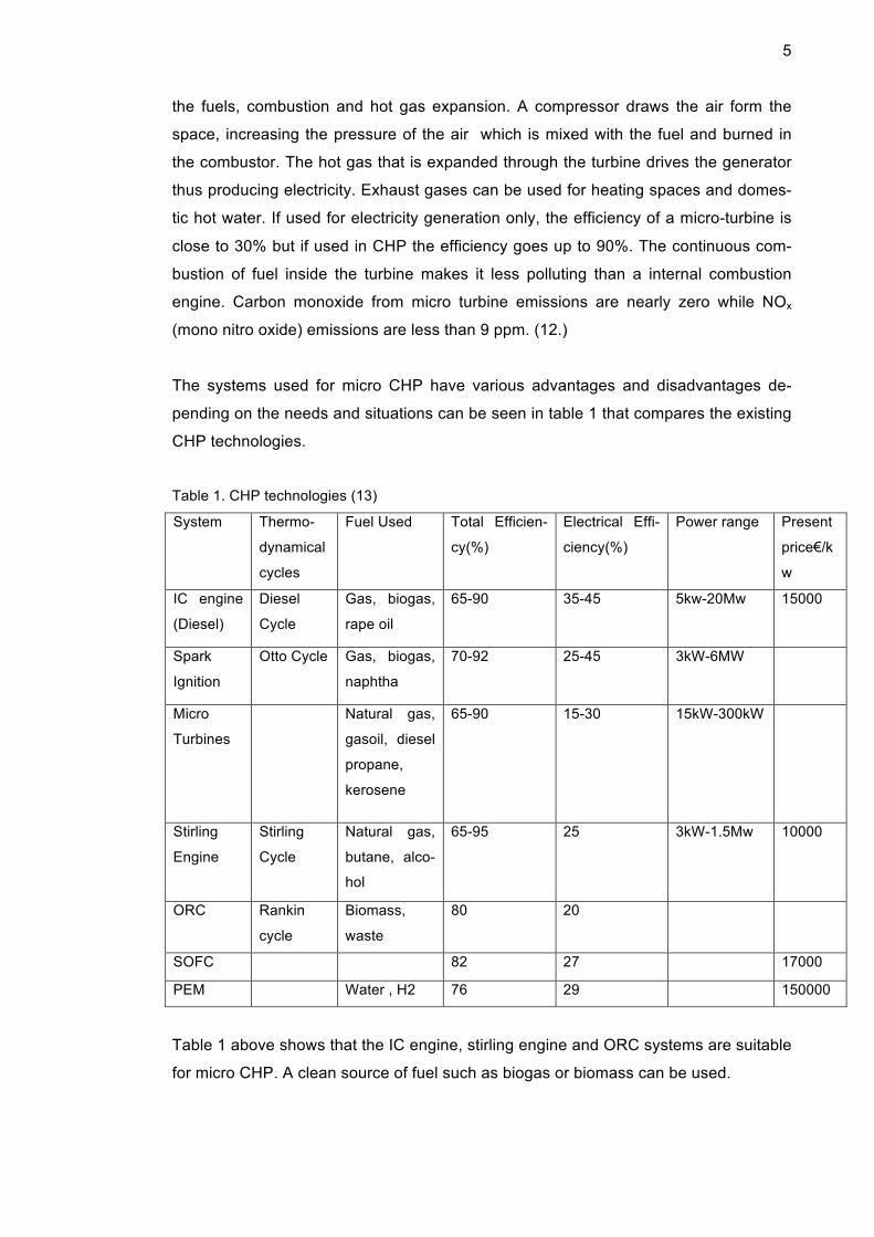
The systems used for micro CHP have various advantages and disadvantages de-
pending on the needs and situations can be seen in table 1 that compares the existing
CHP technologies.
Table 1. CHP technologies (13) System Thermo-
dynamical
cycles
Fuel Used Total Efficien-
cy(%)
Electrical Effi-
ciency(%)
Power range Present
price€/k
w
IC engine
(Diesel)
Diesel
Cycle
Gas, biogas,
rape oil
65-90 35-45 5kw-20Mw 15000
Spark
Ignition
Otto Cycle Gas, biogas,
naphtha
70-92 25-45 3kW-6MW
Micro
Turbines
Natural gas,
gasoil, diesel
propane,
kerosene
65-90 15-30 15kW-300kW
Stirling
Engine
Stirling
Cycle
Natural gas,
butane, alco-
hol
65-95 25 3kW-1.5Mw 10000
ORC Rankin
cycle
Biomass,
waste
80 20
SOFC 82 27 17000
PEM Water , H2 76 29 150000
Table 1 above shows that the IC engine, stirling engine and ORC systems are suitable
for micro CHP. A clean source of fuel such as biogas or biomass can be used.
6
3 Hybrid with renewables
The use of renewable sources of energy is rapidly increasing along with the other mi-
cro-CHP technologies in order to minimize carbon emissions and build energy efficient
buildings. Hydro-power, which needs high head and pressure to create power and
requires very high investment, other sources of renewables like solar energy, geo-
thermal energy and wind power are being used in micro heat and power generation.
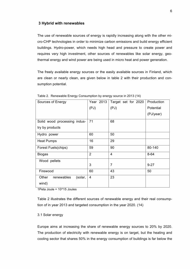
The freely available energy sources or the easily available sources in Finland, which
are clean or nearly clean, are given below in table 2 with their production and con-
sumption potential.
Table 2. Renewable Energy Consumption by energy source in 2013 (14)
Sources of Energy Year 2013
(PJ)
Target set for 2020
(PJ)
Production
Potential
(PJ/year)
Solid wood processing indus-
try by products
71 68
Hydro power 60 50
Heat Pumps 16 29
Forest Fuels(chips) 59 90 80-140
Biogas 2 4 8-64
Wood pellets 3
7
9-27
Firewood 60 43 50
Other renewables (solar,
wind)
4 23
1Peta Joule = 10^15 Joules
Table 2 illustrates the different sources of renewable energy and their real consump-
tion of in year 2013 and targeted consumption in the year 2020. (14)
3.1 Solar energy
Europe aims at increasing the share of renewable energy sources to 20% by 2020.
The production of electricity with renewable energy is on target, but the heating and
cooling sector that shares 50% in the energy consumption of buildings is far below the
7
target in Europe. (15.) Currently, the market of solar energy is comparatively small in
Finland, although there are signs of gradual interest towards solar energy and renew-
able energy sources.The climate and the existing CHP technologies in Finland are the
main factors for the slow interest in solar technologies. Although, Finland has a long
winter, the efficiency in the production of photovoltaic energy is very negligibly low
than in summer time. Solar power can be used for the production of electricity in the
summer time and the heat from the solar thermal can be stored and used for winter.
Hot water is needed throughout the year and space heating is needed in spring and
autumn. There are a few companies that are offering the technologies and services to
the solar market.
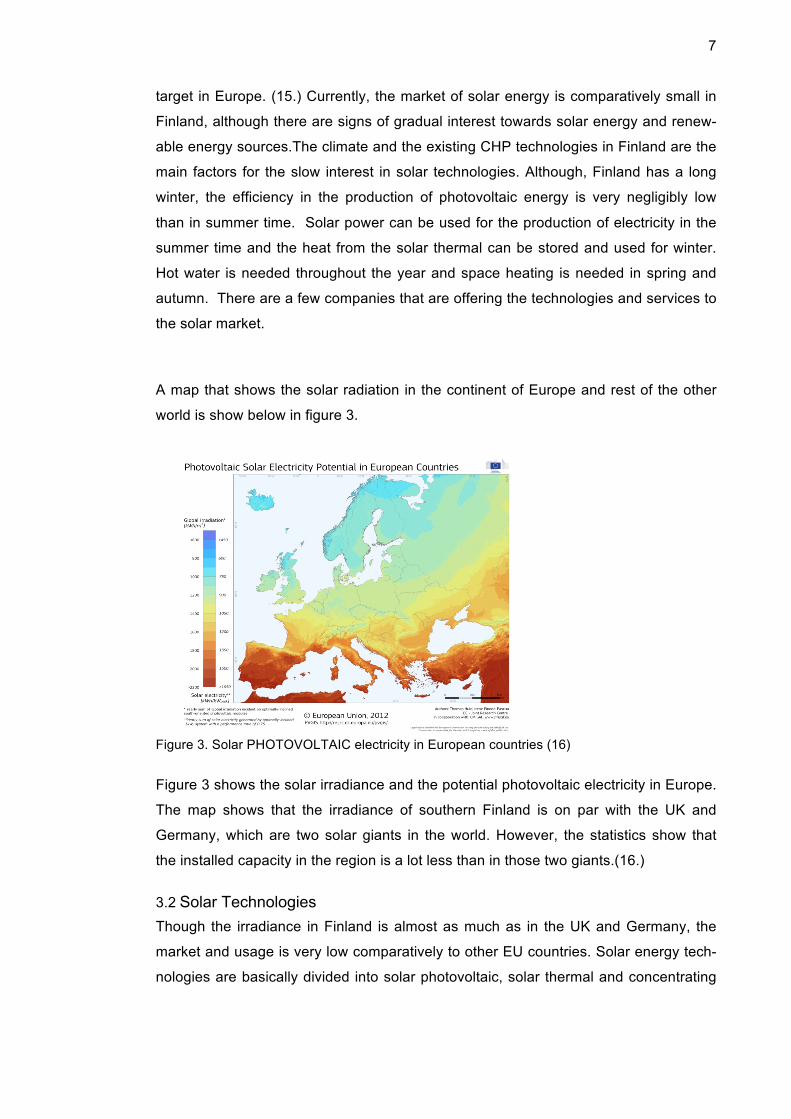
A map that shows the solar radiation in the continent of Europe and rest of the other
world is show below in figure 3.
Figure 3. Solar PHOTOVOLTAIC electricity in European countries (16)
Figure 3 shows the solar irradiance and the potential photovoltaic electricity in Europe.
The map shows that the irradiance of southern Finland is on par with the UK and
Germany, which are two solar giants in the world. However, the statistics show that
the installed capacity in the region is a lot less than in those two giants.(16.)
3.2 Solar Technologies
Though the irradiance in Finland is almost as much as in the UK and Germany, the
market and usage is very low comparatively to other EU countries. Solar energy tech-
nologies are basically divided into solar photovoltaic, solar thermal and concentrating

8
solar power technology. Solar thermal is used for thermal production whereas other
two are used in electricity production. (17.)
3.2.1 Photovoltaic Technology
The term Photovoltaic is used to refer to the conversion of solar light into electricity.
Photovoltaic devices are designed as cells or modules so that they can be placed in
arrays and connected together for producing direct current and voltage. Those voltage
and current can be stored in batteries. (17.)
Figure 4 shows the Photovoltaic production capacity installed in Europe from the year
2000 to the year 2014.
Figure 4. Total Photovoltaic production capacity installed (MWp) (18)
Figure 4 gives a clear picture of the total production of electricity with solar energy.
There was a gradual growth from 2000 to 2011, but it seems to have stopped. (18.)
3.2.2 Solar thermal technology
Solar thermal technology converts sunlight into heat. The main use of the solar ther-
mal system is for domestic hot water and space heating for residential or small office
buildings. Solar thermal energy can also be used to drive a generator and to produce
electricity. (19.)
9
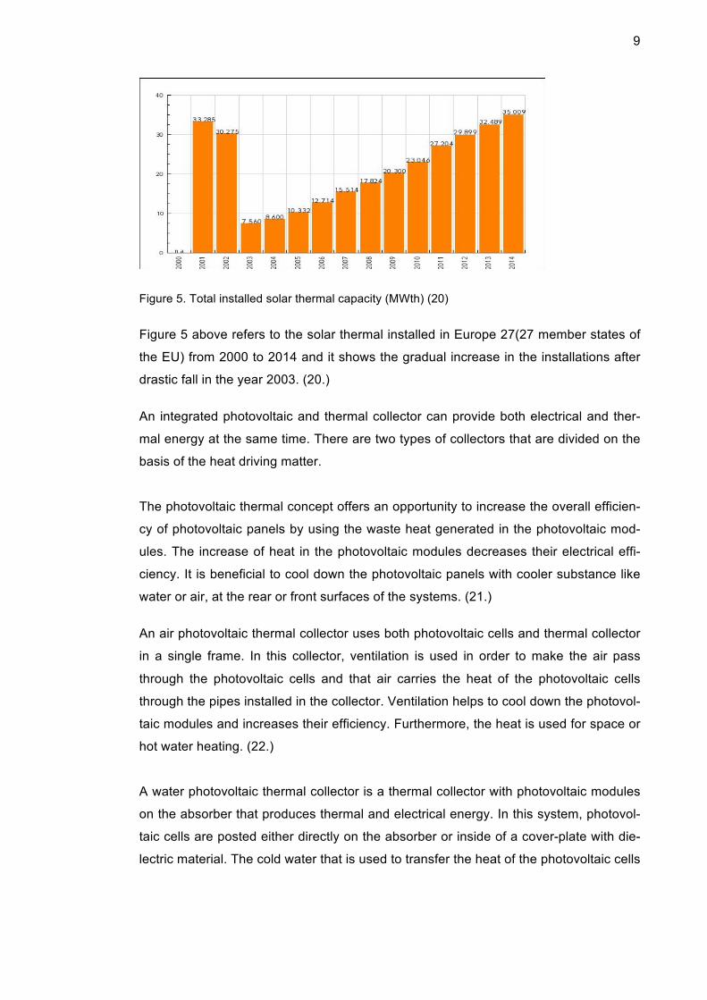
Figure 5. Total installed solar thermal capacity (MWth) (20)
Figure 5 above refers to the solar thermal installed in Europe 27(27 member states of
the EU) from 2000 to 2014 and it shows the gradual increase in the installations after
drastic fall in the year 2003. (20.)
An integrated photovoltaic and thermal collector can provide both electrical and ther-
mal energy at the same time. There are two types of collectors that are divided on the
basis of the heat driving matter.
The photovoltaic thermal concept offers an opportunity to increase the overall efficien-
cy of photovoltaic panels by using the waste heat generated in the photovoltaic mod-
ules. The increase of heat in the photovoltaic modules decreases their electrical effi-
ciency. It is beneficial to cool down the photovoltaic panels with cooler substance like
water or air, at the rear or front surfaces of the systems. (21.)
An air photovoltaic thermal collector uses both photovoltaic cells and thermal collector
in a single frame. In this collector, ventilation is used in order to make the air pass
through the photovoltaic cells and that air carries the heat of the photovoltaic cells
through the pipes installed in the collector. Ventilation helps to cool down the photovol-
taic modules and increases their efficiency. Furthermore, the heat is used for space or
hot water heating. (22.)
A water photovoltaic thermal collector is a thermal collector with photovoltaic modules
on the absorber that produces thermal and electrical energy. In this system, photovol-
taic cells are posted either directly on the absorber or inside of a cover-plate with die-
lectric material. The cold water that is used to transfer the heat of the photovoltaic cells
10
passes from one entrance to the other thus increasing the efficiency of the photovolta-
ic cells and providing heat for space or domestic hot water heating. (22.)
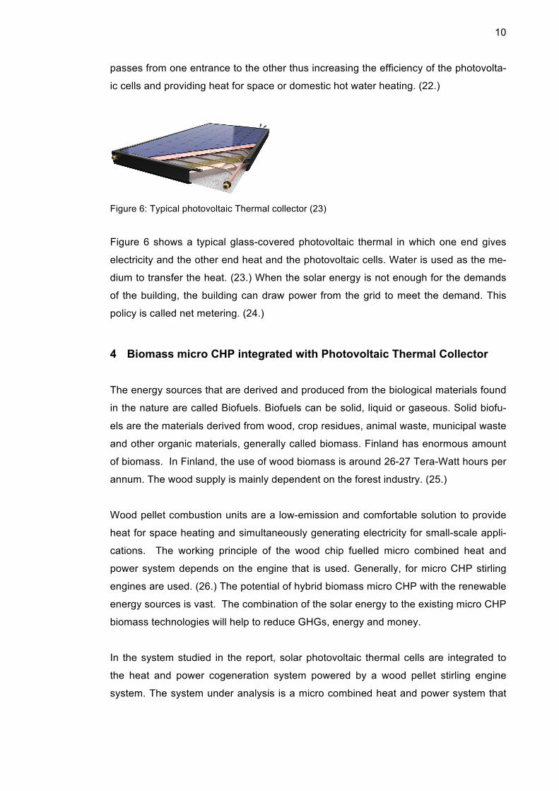
Figure 6: Typical photovoltaic Thermal collector (23)
Figure 6 shows a typical glass-covered photovoltaic thermal in which one end gives
electricity and the other end heat and the photovoltaic cells. Water is used as the me-
dium to transfer the heat. (23.) When the solar energy is not enough for the demands
of the building, the building can draw power from the grid to meet the demand. This
policy is called net metering. (24.)
4 Biomass micro CHP integrated with Photovoltaic Thermal Collector
The energy sources that are derived and produced from the biological materials found
in the nature are called Biofuels. Biofuels can be solid, liquid or gaseous. Solid biofu-
els are the materials derived from wood, crop residues, animal waste, municipal waste
and other organic materials, generally called biomass. Finland has enormous amount
of biomass. In Finland, the use of wood biomass is around 26-27 Tera-Watt hours per
annum. The wood supply is mainly dependent on the forest industry. (25.)
Wood pellet combustion units are a low-emission and comfortable solution to provide
heat for space heating and simultaneously generating electricity for small-scale appli-
cations. The working principle of the wood chip fuelled micro combined heat and
power system depends on the engine that is used. Generally, for micro CHP stirling
engines are used. (26.) The potential of hybrid biomass micro CHP with the renewable
energy sources is vast. The combination of the solar energy to the existing micro CHP
biomass technologies will help to reduce GHGs, energy and money.
In the system studied in the report, solar photovoltaic thermal cells are integrated to
the heat and power cogeneration system powered by a wood pellet stirling engine
system. The system under analysis is a micro combined heat and power system that

11
uses solar energy, integrated with biomass (wood chips/pellet) CHP technology in a
college lab. The produced heat and power can also be used for campus usage. The
heat and power is produced with two sources in the daytime and from the biomass in
nighttime while the load is full on the CHP. The heat source is separated and arranged
in parallel for solar and biomass systems. (27.)
The following diagram (figure 7) shows the layout of the combined heat and power
plant with gas circuits. The operating principle is as same as stirling engine which is
fueled by biomass.
Figure 7. Biomass micro cogeneration of heat and power. (28)
Figure 7 shows the general idea of the generation of heat and power by using stirling
engine and feeding biomass as fuel. It shows that the biomass fed is burned with air
and supplied to the generator via engine thus producing power and heat simultane-
ously. (28.)
There are three advantages of using biomass as a fuel to produce heat and power.
1. The wood pellets or woodchips are easily and abundantly found in Finland thus
beneficial for the biomass market.
2. The carbon emissions are relatively very less than those of fossil fuels, unless
the transportation of the biomass is not near to the plant and therefore, re-
quires a relatively bigger space for storage.
3. The price of biomass is a lot lower than that of fossil fuels. (29.)

12
5 Heat Pump with Photovoltaic panels integrated with Biogas micro CHP
A heat pump is a device with a motor and a compressor. It requires electric power to
run the motor. The motor in turn runs the compressor, compressing a vapor to a high-
er pressure and temperature. The superheated vapor then condenses, releasing the
latent heat to the circulating fluid for heating. (30.)
The studied heating system is based on an air source heat pump, which is supported
by the solar thermal collector system. A water storage tank is used to distribute the hot
water for space heating and domestic hot water.
Different heat pumps have different working principles and mediums to carry the heat
from one place to another. Some other characteristics of th available heat pumps are
presented in the table 3.
Table 3. Features of various Heat Pumps. (31)
Features Outdooor Air Exhaust air Ground (Ground) Wa-
ter
Availabilty Everwhere Ventilation
system
High in the
earth,s crust
Restricted
Capacity of
source
Upon Volume
flow rate
Limited when
air exchange
Upon bore-
hole,drysoil and
wet soil
Range of ca-
pacity upon
ground water
and surface
water
Temperature
Range
-20°C-40°C 20°C-28°C 1°C-15°C 8°C-13°C
Frosting Risk Up to -7°c In case of
coupling with
heat recovery
Almost none none
Permision None None Required required
Heating Capa-
city(2016 est.)
2 980226 kW 108 807kW 1 517810kW 365071kW
Table 3 can be used to compare the advantages and disadvantages of the available
pumps. (31)
13
Heat pump systems with photovoltaic thermal collectors and a borehole heat ex-
changer as heat source can achieve higher efficiencies and help providing cooling to
the photovoltaic modules. The borehole can be used to store heat to be used in winter.
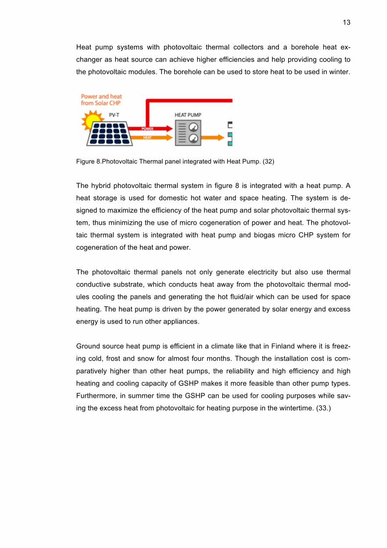
Figure 8.Photovoltaic Thermal panel integrated with Heat Pump. (32)
The hybrid photovoltaic thermal system in figure 8 is integrated with a heat pump. A
heat storage is used for domestic hot water and space heating. The system is de-
signed to maximize the efficiency of the heat pump and solar photovoltaic thermal sys-
tem, thus minimizing the use of micro cogeneration of power and heat. The photovol-
taic thermal system is integrated with heat pump and biogas micro CHP system for
cogeneration of the heat and power.
The photovoltaic thermal panels not only generate electricity but also use thermal
conductive substrate, which conducts heat away from the photovoltaic thermal mod-
ules cooling the panels and generating the hot fluid/air which can be used for space
heating. The heat pump is driven by the power generated by solar energy and excess
energy is used to run other appliances.
Ground source heat pump is efficient in a climate like that in Finland where it is freez-
ing cold, frost and snow for almost four months. Though the installation cost is com-
paratively higher than other heat pumps, the reliability and high efficiency and high
heating and cooling capacity of GSHP makes it more feasible than other pump types.
Furthermore, in summer time the GSHP can be used for cooling purposes while sav-
ing the excess heat from photovoltaic for heating purpose in the wintertime. (33.)

14
An example of a building that has used solar photovoltaic-thermal technology along
with a ground source heat pump for the power and heat required for building.
Figure 9: EcoTerraTM Home (34)
Figure 9 above is a Canadian Net Zero Energy building in which solar photovoltaic
thermal system is integrated with heat pump and the thermal storage.
A CHP system based on biogas is simple and efficient. Biogas is generated during the
fermentation of organic material. Kitchen waste and other organic waste fermentation
is one of the easiest ways to get biogas. Biogas is produced when the bacteria de-
grade organic matter in the absence of air. Biogas contains of 30-40% of carbon diox-
ide and 55-65% of methane. The biogas is used in organic rankine cycles or micro
turbine to produce heat and power once it is cleaned and dewatered. Furthermore, the
slurry produced after the process can be used as agricultural fertilizer. (35.)
15
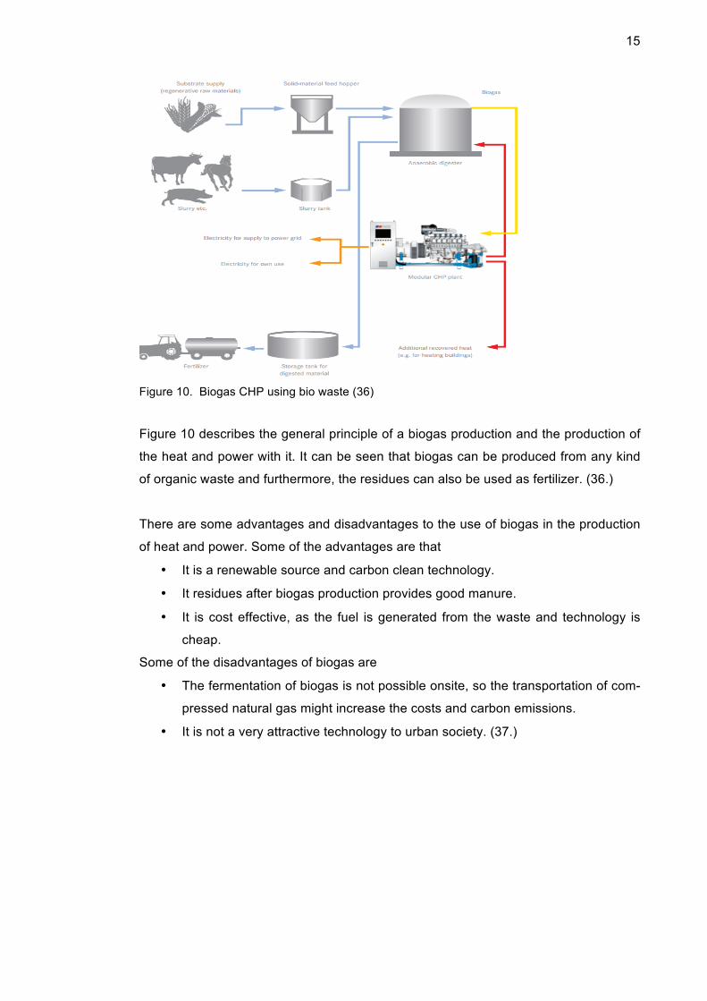
Figure 10. Biogas CHP using bio waste (36)
Figure 10 describes the general principle of a biogas production and the production of
the heat and power with it. It can be seen that biogas can be produced from any kind
of organic waste and furthermore, the residues can also be used as fertilizer. (36.)
There are some advantages and disadvantages to the use of biogas in the production
of heat and power. Some of the advantages are that
• It is a renewable source and carbon clean technology.
• It residues after biogas production provides good manure.
• It is cost effective, as the fuel is generated from the waste and technology is
cheap.
Some of the disadvantages of biogas are
• The fermentation of biogas is not possible onsite, so the transportation of com-
pressed natural gas might increase the costs and carbon emissions.
• It is not a very attractive technology to urban society. (37.)

16
6 Photovoltaic integrated Rainwater Fuel cell CHP
The uses of renewable energy sources are gradually increasing. Solar photovoltaic
and solar thermal or sometimes wind energy is used with fuel cell CHP technology. It
is one of the best options for energy savings and for cutting GHGs emission.
Fuel cell micro CHP is still in a developing stage and relatively more expensive than
the existing technologies. PEMFCs require hydrogen for operation and SOFCs use
hydrogen and carbon monoxide as fuel. Fuel cells can generate the highest proportion
of electricity of any CHP technology. PEM FC has been developed and used for many
years though it has not been used for energy applications. Electrolysis of water has
been in practice for centuries and it has been used to produce hydrogen for industrial
applications. In water electrolysis, an electric current is used to split the hydrogen and
oxygen. Rainwater is also suitable for electrolysis. The electricity required to the
breakdown of water can be provided by photovoltaic cells or wind energy. The excess
electricity can be further used for other purposes, Due to the flexibility to use with solar
or wind energy, the electrolyser has been now gaining attention towards clean energy
production. (38.)
The diagram in figure 11 below shows the general principle of a solar supported elec-
trolyser that provides hydrogen gas to the fuel cell.
Figure 11. Photovoltaic integrated with PEM fuel cell (39)
Figure 11 shows the photovoltaic module integrated with PEM fuel cell micro CHP. It
also consists of a water tank, electrolyser, battery for the storage of the electricity gen-

17
erated with solar panels and a hydrogen tank for the storage of hydrogen fuel. The
electrolyser used produces the hydrogen gas, which is stored or fed to the FC system.
There are batteries to supply electricity required to the breakdown of the water when
the photovoltaic cells are not producing enough electricity. The proton exchange
membrane fuel cell, sometimes called a polymer electrolyte membrane fuel cell, uses
a water-based acidic polymer membrane as its electrolyte with platinum based elec-
trodes. Hydrogen fuel is processed at the anode where electrons are separated from
protons on the surface of a platinum based catalyst. The protons pass through the
membrane to the cathode and the electrons travel to the external circuit thus generat-
ing electrical output. The cathode combines the protons and electrons with oxygen
producing water. (40.)
The electrode used in the fuel cell system is the only drawback of the system as it is
very expensive. Platinum and sometimes ruthenium are also used as the electrodes in
PEM, which are expensive.
The reaction of the breakdown of the water during the process of electrolysis is stated
below.
Anode reaction H2Oà2H++1/2O2+2e-
Final Reaction H2OàH2+1/2O2
Fuel cell reaction of the Proton exchange membrane is shown below,
Anode reaction H2à2H++2e-
Cathode reaction 2H++1/2O2+2e-à H2O
Total reaction H2+1/2O2à H2O (41.)
Although fuel cell micro CHP is still in the developing phase there are some devices
for micro CHP.

18
Table 4 represents the existing fuel cell micro-chp systems and the prices along with
the price of the devices in the year 2014.
Table 4. Market Prices of some Fuel cell devices (42)
Systems Price € (2014)
PEM
Toshiba 0.7kw
Panasonic 1kW
Plug Power 5kW
22,500
23 900
70,000
SOFC
Kyocera 0.7kW
Sulzer Hexis 1kW
70,000 per kW
55,000
AFC (5-10kW) 10,000 per kw
Ballard 1kw
Table 4 gives the market overview of fuel cell technologies and there are some other
fuel cell micro CHP appliances found in Europe that are in use.
1. Hexis Galileo 1000N from Switzerland which uses SOFC as fuel.
2. Baxi Innotech from Germany uses PEMFC
3. Ceres from UK uses SOFC
4. Danther from Denmark using PEMFC and high temperature.
5. FutureE from Germany (43.)
The advantages of fuel cell technology are that
• Fuel cell technology has higher efficiency than existing of CHP systems.
• It is carbon free because of the breakdown of water. There is no need to burn
fuel.
• It uses renewable energy sources.
• It has no moving parts, so it is noise free.
• It can run continuously as long as fuel is available and water can be used for
fuel.
The disadvantages of the fuel cell technology are that
• The electrode is very expensive, requiring a high capital cost.
• It is still in an evolving phase for CHP. (44.)

19
7 Case studies
There are various cases that use two or more renewable energy technologies together
and get a better result than a conventional boiler system. Below some European cas-
es are introduced.
7.1 Photovoltaic Thermal integrated Heat Pump
In Northants, United Kingdom, a low-carbon four-bedroom detached building is built
with the latest energy efficient solar technology integrated into the building. Solar
thermal and photovoltaic systems have been used to meet the heat and power of the
building demands. The carbon footprint of the photovoltaic thermal panels installed is
smaller than the carbon footprints of conventional systems. The photovoltaic thermal
panels are integrated with a ground source heat pump and an inter seasonal heat
storage in an earth energy bank under the foundation of house which enables the low
cost for heat and power. The photovoltaic thermal is 12 solar angel 250Wp that has
been installed in the roof of the building. The estimated electric output per annum-
2600kWh and thermal output per annum-3000 kWh. The annual carbon savings are
around 2 tonnes (45.)
7.2 Solar CHP in Sweden
In Härnösand, Sweden, a solar CHP has been installed with the peak capacity of
20kWp electricity and 100kWp heat. The photovoltaic thermal module produces ther-
mal heat up to 75°C and electrical power 230V, by focusing the light on high efficiency
photovoltaic cells, thus generating hot water and electricity at the same time. The pho-
tovoltaic thermal collector used was Absolicon X10. (46.)
Figure 12. Diagram of Solar Collector used for CHP in Sweden (47)
20
Figure 12 shows the features and different parts of the Absolicon solar collector that
has been used in Härnösand.
7.3 Mobile Biomass CHP
Oulu University of Applied Sciences has built a mobile CHP unit for distributed energy
production. The system is built in a container which consists of an internal combustion
engine, a generator and a unit to feed the energy to the grid. The container can easily
be moved at different locations where the heat and power are required as well as to
the site nearby the fuel is produced (wood pellet or biogas) units, in order to reduce
cost of fuel transportation and helps reduce carbon emissions. The device that is used
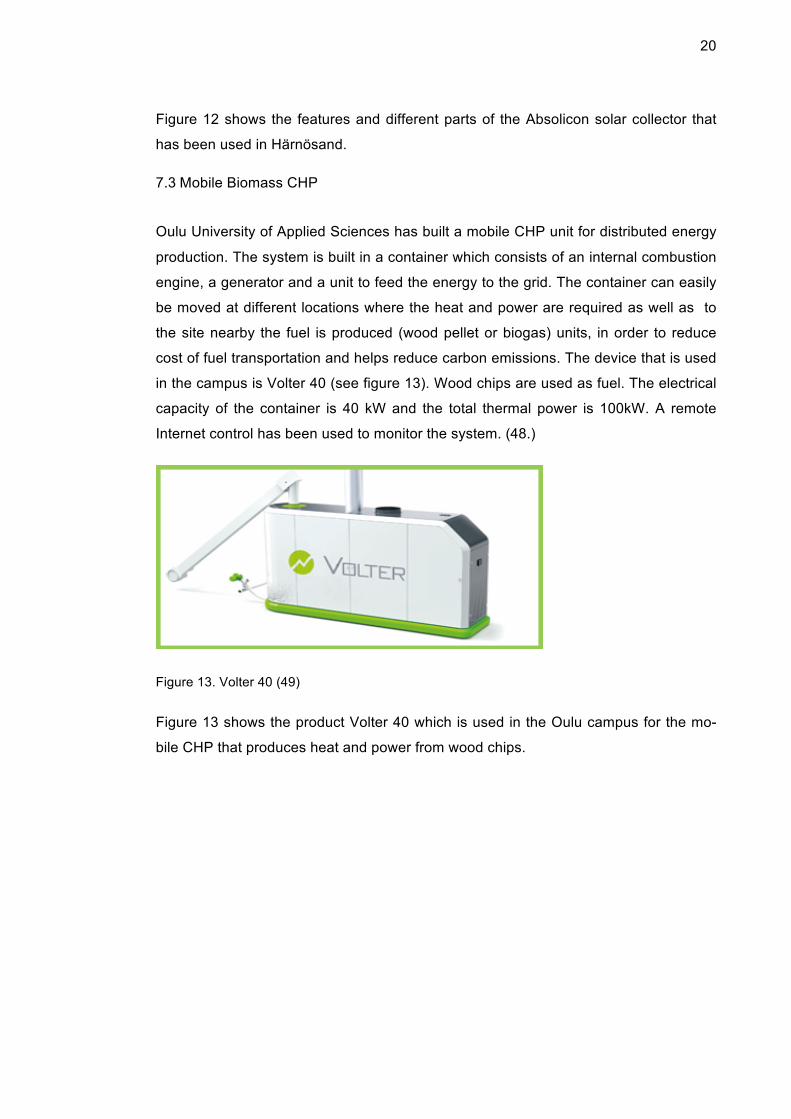
in the campus is Volter 40 (see figure 13). Wood chips are used as fuel. The electrical
capacity of the container is 40 kW and the total thermal power is 100kW. A remote
Internet control has been used to monitor the system. (48.)
Figure 13. Volter 40 (49)
Figure 13 shows the product Volter 40 which is used in the Oulu campus for the mo-
bile CHP that produces heat and power from wood chips.

21
The other technologies used for micro CHP available in the European are listed below
in table 5.
Table 5. Available Products in Europe for Biomass Micro CHP (50)
Products Electrical output(kW) Efficiency(Total) %
Senertec Dachs 5.5 5.5 27(88–99)
EC Power XRGI 15 15 30(92)
Viessmann Vitobloc 200 18 32(96)
Capstone C30 LP 28 25
Buderus Loganova EN50 50 34(88)
Table 5 also shows some of the existing products for biomass micro CHP along with
their potentials and efficiency of the products. This may assist in the process to
choose a product for the campus.
7.4 Heat pump and Micro CHP
In Norte Dame Primary School, Glasgow, United Kingdom, a ground source heat
pump and biomass CHP are integrated to provide the energy for building. In the build-
ing underfloor heating has been used to optimize the space. The operating tempera-
ture of the heating system of the school is 45°C which lends low surface temperatures
for the radiators making the building safe for students. The devices that have been
used in the school are two sets of Baxi Commercial Division products, which produce
27.5 kW of electricity during the day and 16.5kw at night according to the requirement
of the building. Baxi monitors the micro CHP through a modem link installed in plant-
room. After the installation of the CHP in the school they were able to save around 60,
000€ and cut the emissions by 90,000tonnes. (51.)

22
8 Environmental and Economic Performance Analysis
The cost of electricity from the national grid for electric and thermal energy is rising
year by year. In the EU, over 100,000 people are employed in the heating industry and
over eight million boilers are sold in EU. Micro CHP is one of the heating industry’s
next generation products worth €20billion a year. The EU innovation union has target-
ed to invest 3% of its gross domestic product on R and D by 2020 for the micro-CHP
creating around four million jobs and adding €800 million in the GDP by 2025. (52.)
Table 6. Contribution from the Renewables (53)
Sources Savings kwh/a Savings €/a Investment CO2 savings
Ground Source
Heat Pump
14000-17000 1800-2200 14000-20000 8 million tons
Air to Air 2000-7000 250-800 1500-2500
Photovoltaic 2-4 euro per
watt
Table 6 illustrates the contribution of the solar PV energy and different heat pumps in
Finland towards the emission and bill cuts.
The traditional and currently used fuel types produce plenty of greenhouse gases. In
order to diminish that and create a green world, renewable sources should be used
more. The table 7 shows the emissions from the combustion of traditional sources of
fuel for the cogeneration of heat and power for a house that uses 20000kwh/year.
(54.)
Table 7: Carbon Emission from Different Fuel Combustion. (54)
Fuel Net Calorific
Value MJ/kg
Carbon Con-
tent
%
Life cycle Co2
emissions(kg/MWh)
Annual Total
emissions for a
house(kg)
Oil 42 85 314 6280
Coal 29 75 414 8280
LPG 46 82 259 5180
Natural Gas 38 75 227 4540
Wood pellets 17 45 90 1500
23
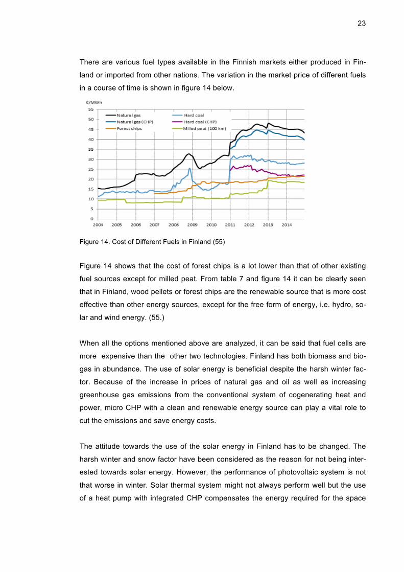
There are various fuel types available in the Finnish markets either produced in Fin-
land or imported from other nations. The variation in the market price of different fuels
in a course of time is shown in figure 14 below.
Figure 14. Cost of Different Fuels in Finland (55)
Figure 14 shows that the cost of forest chips is a lot lower than that of other existing
fuel sources except for milled peat. From table 7 and figure 14 it can be clearly seen
that in Finland, wood pellets or forest chips are the renewable source that is more cost
effective than other energy sources, except for the free form of energy, i.e. hydro, so-
lar and wind energy. (55.)
When all the options mentioned above are analyzed, it can be said that fuel cells are
more expensive than the other two technologies. Finland has both biomass and bio-
gas in abundance. The use of solar energy is beneficial despite the harsh winter fac-
tor. Because of the increase in prices of natural gas and oil as well as increasing
greenhouse gas emissions from the conventional system of cogenerating heat and
power, micro CHP with a clean and renewable energy source can play a vital role to
cut the emissions and save energy costs.
The attitude towards the use of the solar energy in Finland has to be changed. The
harsh winter and snow factor have been considered as the reason for not being inter-
ested towards solar energy. However, the performance of photovoltaic system is not
that worse in winter. Solar thermal system might not always perform well but the use
of a heat pump with integrated CHP compensates the energy required for the space
24
heating and domestic hot water. The excess heat from the summer can be stored in
the GSHP for winter purposes. Furthermore, the GSHP can be used for cooling in the
summer time if necessary.
A third of the Finnish land mass is occupied by forests. Wood is the most important
source of bioenergy in Finland, almost a quarter of the total energy consumption,
which is an important factor when reducing carbon emissions. The various cases in-
troduced above clearly shows that there is significant reduction in the costs and
greenhouse gas emissions after the use of clean energy technologies for cogeneration
of power and heat are employed. (56.).
The main purpose of the thesis was to analyze the possibility to construct a movable
hybrid micro CHP for a lab at the Metropolia Campus. The combination of biomass
micro CHP with a ground source heat pump and solar photovoltaic thermal collector in
a sea container can be a good option. A remote control system can be installed to
both monitor the whole system and for sun tracking. Sun tracker helps to monitor the
solar energy and helps to switch the CHP system on when the solar energy is negligi-
ble.
A sea container is used to fit a biomass micro CHP device (a volter 40 can be used as
it is available in Finland and has been already in use). The solar panels can be in-
stalled on the roof of the container or can be used on the roof of the campus building,
in necessary angle. Ground source heat pump can installed close to the container or
within the campus building for the heating purpose of the building for which the cam-
pus needs a permit to dig the borehole. The heat from the solar panels can be used to
heat the building. When heating is not required the excess heat can be stored in the
installed heat pump.
9 Conclusion
In essence, to achieve the target set by the EU, that is to reduce the carbon emis-
sions and energy costs by using renewable energy source, the use of micro CHP with
solar, wind and geothermal energy is very productive and profitable. This project was
done in order to study the possibility to make a renewable hybrid micro CHP for a lab
of the Metropolia Campus to supply the heat and power produced by the system to the
campus building.

25
In residential areas, which are connected to the district heating system where the
transmission loss is comparatively low, the use of micro CHP is not very productive,
though integrating the solar energy and wind energy with district heating might be ef-
fective in the control of GHG emissions. Micro CHP reduces energy costs by 30% and
CO2 by 1.5 tonnes from a typical house.
Solar CHP and using solar energy with Biomass fuelled CHP in small scale, as we
have mentioned in the report, might be very effective to environment and economy.
Tax reduction for new technologies that use renewable energy sources will encourage
the adoption of the technologies. Increasing the awareness about micro CHP and its
advantages might a play vital role to encourage locals to increase investments in the
renewables and the technologies thus helping in the emission cuts.
The report provided an outlook of the hybrid micro CHP that can be built for a lab of
the campus of Helsinki Metropolia University of Applied Sciences. The device when
built in lab can provide the students (future engineers) the possibility of using renewa-
ble energy sources along with existing technology at the same time to achieve sus-
tainable and carbon free environment. Students can use the idea to implement to their
clients, when working, describing the benefits of the renewable resources and their
uses.
26
10 Reference
1. COGEN Europe: The benefits of Micro CHP [online] .Brussels, Belgium; The European Association for the Promotion of Cogeneration. URL:http://www.cogeneurope.eu/medialibrary/2015/05/19/d6648069/miro-CHP%20study_merged.pdf. Accessed on 10 February 2016
2. COGEN Europe; Micro CHP delivering energy savings in framework of Energy Efficieny Directive [online]. 28.04.2014; URL:http://www.cogeneurope.eu/medialibrary/2013/07/10/3abaf321/COGEN%20Europe_micro%20CHP%20position%20paper.pdf . Accessed on 15 February2016
3. Harisson J, Micro CHP system. URL: http://www.microchap.info/introduction_to_micro_chp.htm Accessed on 18 February2016
4. Orr G , Dennish T, SummerField I, Purcell F: Commercial Micro-CHP Field Trial Report [online].2011. URL:http://www.seai.ie/Publications/Renewables_Publications_/CHP/Commercial_micro-CHP_Field_Trial_Report.pdf. Accessed on 13 February 2016
5. Fuel cell basics [online]: 2012 Url:http://www.fuelcelltoday.com/media/1637138/fc_basics_technology_types.pdf. Accessed on 18 February 2016
6. A Kerry-ann; Stationary fuel cells-An overview [online]. July 2010. URL:http://site.ebrary.com/lib/metropolia/detail.action?docID=10196353&p00=stationary+fuel+cell Accessed on 15 March 2016
7. Pratt JW, Klebanoff L, M-Ramos K, A-Akhil A, Curgus D B, Schenken K L; Proton Exchange Membrane Fuel Cells for Electrical Power Generation On-Board Commercial Airplanes [online]. Published on May 2011
URL:www1.eere.energy.gov. Accessed on 19 April 2016
8. Fuel cells; Proton Exchange Membrane Fuel Cell;[online];
URL:www.eere.energy.gov/hydorgenandfuelcells Accessed on 23 March 2016
9. Thombare D G; Stirling Engine: Micro CHP system for residential building ap-
plication [online]. URL:http://www.academia.edu/2000706/Stirling_Engine_MicroCHP_System_for_Residential_Application Accessed on 16 March 2016
27
10. Simander G, Krawinkler R, Trnka G; Micro CHP System:state-of-the art [online]. European Commission, 2006.
URL:https://ec.europa.eu/energy/intelligent/projects/sites/ieeprojects/files/projects/documents/green_lodges_micro_chp_state_of_the_art.pdf Accessed on 24 February 2016
11. Kaminski J; Introduction to thermal and fluids Engineering, (p-330)
12. Micro-Turbines for power generation; Advanced Technology Group (PE-mech)
[online]. URL:www.oocities.org/microturbines. Accessed on 24 February 2016
13. Comparison of the existing system of micro CHP, Catalogue of CHP technolo-gies. URL:https://www.epa.gov/sites/production/files/201507/documents/catalog_of_chp_technologies.pdf Accessed on 14 February 2016
14. Karhunen A, Ranta T, Heinimiö J, Kangas E; Market of Biomass Fuels in Fin-land-an Overview 2013[online].
URL: www.bioenefrgytrade.org. Accessed on 2 May 2016.
15. Entchev E, Tzscheutschler P; Energy in Buildings and Communities Pro-
gramme [online]. Integration of Micro generation and related technologies; Oc-tober 2014. URL:http://www.ieaebc.org/fileadmin/user_upload/docs/Annex/EBC_Annex_54_Micro-Generation_Integration_Final_Report.pdf Accessed on 11 April 2016
16. Hakkarainen T, Tsupari E, Hakkarainen E, Ikäheimo J; Solar Photovoltaic electricity in European Countries; The role and opportunities for Solar energy in Finland and Europe [online].
URL: http://www.vtt.fi/inf/pdf/technology/2015/T217.pdf Accessed on 8 April 2016
17. DOE Solar Energy and Technologies Program [online]. Overview an dhigh-loights,2005. US Department of Energy URL:https://www1.eere.energy.gov/solar/pdfs/39081.pdf Accessed on 19 March 2016
18. Solar PV installed in Europe [online]. Eurobserver databases; observ-
er.catajour online. Accessed on 26 March 2016
19. Ivancin A, Mugnier D, Stryj-Hipp G, Weiss W; Solar thermal road map: Re-
newable Heating and cooling: European technology Platform [online]. URL:http://www.rhcplatform.org/fileadmin/user_upload/Structure/Solar_Thermal/Download/Solar_Thermal_Roadmap.pdf
Accessed on 16 March 2016
20. Solar Thermal in Europe [online]. Eurobserver databases; observer.catajour
28
online. Accessed on 26 March 2016
21. Chow T.T. A review on photovoltaic/thermal hybrid solar technology [online]. 2010 URL:http://www.sciencedirect.com/science/article/pii/S0306261909002761 Accessed on 2 May 2016
22. Strategic Research Priorities for Solar Thermal Technology; European Tech-nology Platform on Renewable Heating and cooling [online]. URL:http://www.rhcplatform.org/fileadmin/Publications/Solar_Thermal_SRP_single_page.pdf Accessed on 20 April 2016
23. Bosanac M, Sorensen B, Katic I, Bardan J, Nielsen B, Sornesen H; Photovol-taic-Thermal Solar collectors and their Potential in Denmark [online]. URL: https://www.ecn.nl/fileadmin/ecn/units/egon/pvt/pdf/EFP1713_00-0014.pdf Accessed on 17 April 2016
24. Walker A. Net metering; Deliveries of Solar Energy. page 18: Solar Energy Technology for Building
25. Kuitto P Juhani. Biomass CHP in Finland; 2011[online]. URL:http://www.crossborderbioenergy.eu/fileadmin/user_upload/Pekka-Juhani_Kuitto__FINBIO__Vienna_12_May_2011.pdf Accessed on 4 April 2016
26. Obernberger I; Innovative Biomass CHP technologies [online].
URL:http://www.ieabcc.nl/workshops/task32_Beijing_WS/A3%20Presentation%20ORC%20Stirling.pdf Accessed on 4 March 2016
27. Bazan P, German R, Awad A; Optimized Operation of Photovoltaic and micro CHP hybrid system [online]. Published on 23 January 2016. URL: http://link.springer.com/article/10.1007/s40866-016-0004-3 Accessed on 22 March 2016
28. Thombare D.G; Stirling Engine-Micro CHP for Residential Application [online]. URL:http://www.academia.edu/2000706/Stirling_Engine_Micro-CHP_System_for_Residential_Application Accessed on 23 April 2016
29. Remrova M, Wildbacher N; Biomass Energy for heating and hot water in Bela-rus [online].2005 URL: http://energoeffekt.gov.by/bioenergy/htdocs/en/trainings_report1.html Accessed on 16 March 2016
30. M Maehulm.Energy Informative; Biomass Energy Pros and cons[online].2012 URL:http://energyinformative.org/biomass-energy-pros-and-cons/ Accessed on 11 April 2016
31. Walker A; Solar space heating (P 251); Solar Energy Technology for Building
29
32. Häkimies S, Hirvonen J, Jokisalo J, Knuuti A, Kosonnen R, Paiho S, Pulakka S; Heat Pumps in energy and cost efficient building in Finland [online]. VTT. URL: http://www.vtt.fi/inf/pdf/technology/2015/T235.pdf Accessed on 23 February 2016
33. Wu Ruqun; Energy Efficiency Technologies-Air Source Heat Pump vs. Groun
Source Heat Pump [online]. Sustainable Development;2009. URL: http://www.ccsenet.org/journal/index.php/jsd/article/viewFile/2986/2757 Accessed on 18 April 2016
34. Häkimies S, Hirvonen J, Jokisalo J, Knuuti A, Kosonnen R, Paiho S, Pulakka
S; Heat Pumps in energy and cost efficient building in Finland [online].VTT. URL: http://www.vtt.fi/inf/pdf/technology/2015/T235.pdf Accessed on 23 February 2016
35. Agrahari RP, Tiwari GN; Center for energy Studies,India; The Production of Biogas using Kitchen waste [online]. International Journal of Sciences; De-cember 2013 URL:https://www.scribd.com/document/248013558/Production-of-BioGas-Using-Kitchen-Waste Accessed on 3 April 2016
36. Combine heat and power from Biogas; [online].
URL: http://www.ddperu.com.pe/pdf/BIOGAS.pdf Accessed on 28 April 2016
37. Advantages and Disadvantages of Biogas [online]. Renewable Energy; April 29 2010; URLhttp://www.economywatch.com/renewable-energy/advantages-of-biogas.html Accessed on 4 may 2016.
38. Water Electrolysis and renewable energy system [online]. URL: http://www.fuelcelltoday.com/media/1871508/water_electrolysis___renewable_energy_systems.pdf Accessed on 11 May 2016
39. Simoes I, Coasterg M; Energy Cost analysis of solar hydrogen hybrid sys-tem for standalone applications: Photovoltaic integrated with PEMFC [online]. 20 May 2008.International Journal of Hydrogen Energy URL: http://inside.mines.edu/~mSimoes/documents/pap3.pdf Accessed on 12 April 2016
40. Fennema E, Freese H; Higher Efficiencies for Micro CHP using Fuel Cells [online]. KIWA technology; Published on 04.09.2014. Accessed on 10 March 2016
41. Polymer Electrolyte Membrane Fuel Cell [online].2005. URL. http://www.fuelcell.no/fuel_cell_types_pemfc_eng.htm Accesed on 26 April 2016
42. Curtin S, Gangi J, Fuel cell technologies Market Report [online].2014.

30
URL:http://energy.gov/sites/prod/files/2015/10/f27/fcto_2014_market_report.pdf Accessed on 18 March 2016
43. Siegel RP; Fuel cell Energy Pros and cons [online]. Published on 10 May
2012. URL:http://www.triplepundit.com/special/energy-options-pros-and-cons/fuel-cell-energy-pros-cons/ Accessed on 2 April 2016
44. Clopton new building [online]. Low Carbon House; Solar angel Future Genera-tionUK URL:http://media.wix.com/ugd/cd1534_216ab6d9a4654b12b28528a526d375eb.pdf Accessed on 13 March 2016
45. Pasonen R, Mäki K, Sipilä K, Alanen R;Arctic Solar Energy Solutions [online].VTT Tecnology 15. URL:http://www.vtt.fi/inf/pdf/technology/2012/T15.pdf Accessed on 14 April 2016
46. Abscolin X10 used for CHP in Sweden. [online]
URL:http://consorcioctdenergy.blogspot.fi/2014/02/colectores-solares-con-tecnologia-de.html Accessed on15 April 2016
47. Oulun Ammatikorkeakoulu, Finland; Electricity and Heat generation[online].
Research and Development,2014 URL:http://www.oamk.fi/hankkeet/chp/english/electricity-and-heatgeneration/ Accessed on 26 April 2016
48. Volter 40; [online]
URL: http://volter.fi/portfolio/volter-indoor-model/ Accessed on 6 May 2016
49. Wit J, Näslund M; Mini and Micro co-generation [online]. URL:http://www.buildup.eu/sites/default/files/content/MiniMicroCHP-ICCIConf2011.pdf Accessed on 21 March 2016
50. The balance of Power; Notre dame Primary School; Glasglow [online]. Pub-
lished on Feb 2015; URL www.cibsejournal.com
Accessed on 29 March 2016 51. Lyon C. Micro-CHP delivering the EU’s Energy and climate objectives; CO-
GEN Europe [online]. 25 February 2015. URL:http://www.cogeneurope.eu/medialibrary/2013/07/09/cb86ae0f/COGEN%20Europe_micro%20CHP%20position%20paper.pdf. Accessed on 25 April 2016
52. The future of heat pumps in Finland [online]. Finnish Heat pump Association URL:http://www.sulpu.fi/documents/184029/189661/The%20future%20of%20

31
Heat%20Pumps.pdf. Accessed on 12 March 2016
53. Fuels for heating and power. Carbon Emission from different fuel source
[online]. URL:http://www.biomassenergycentre.org.uk/portal/page?_pageid=75,163182&_dad=portal&_schema=PORTAL.
Accessed on 2 May 2016 54. Karhunen A, Ranta T, Heinimiö J, Kangas E; Market of Biomass Fuels in Fin-
land-an Overview 2013[online]. URL:http://www.bioenergytrade.org/downloads/iea-task-40-country-report-2014-finland.pdf Accessed on 2 May 2016.
55. Statistic Finland. Fuel prices in Finland 2004-2014 [online].
URL:http://www.stat.fi/til/ehi/2014/01/ehi_2014_01_2014-0619_tie_001_en.html Accessed on 23 March 2016
56. Energy Matters; Micro CHP potential analysis European level Report; CODE2
[online]. Published on December 2014 URL:http://www.code2-project.eu/wp-content/uploads/D2.5-2014-12-micro-CHP-potential-analysis_final.pdf Accessed 12 April 2016


1

![+91 98201 27782 +91 99200 23837 - … DHALIWAL - Saka : The Martyrs of Nankana Sahib [ Punjabi ] SHRADDHA MUSALE - Wrong Side Raju [ Gujarati ] (2017) YAMI GAUTAM - Kaabil](https://img.pdfslide.us/doc/110x75/5aa737007f8b9a294b8bcad6/91-98201-27782-91-99200-23837-dhaliwal-saka-the-martyrs-of-nankana-sahib.jpg)