Embed Size (px)
DESCRIPTION
rainwater harvesting for industrial area of surat
Citation preview
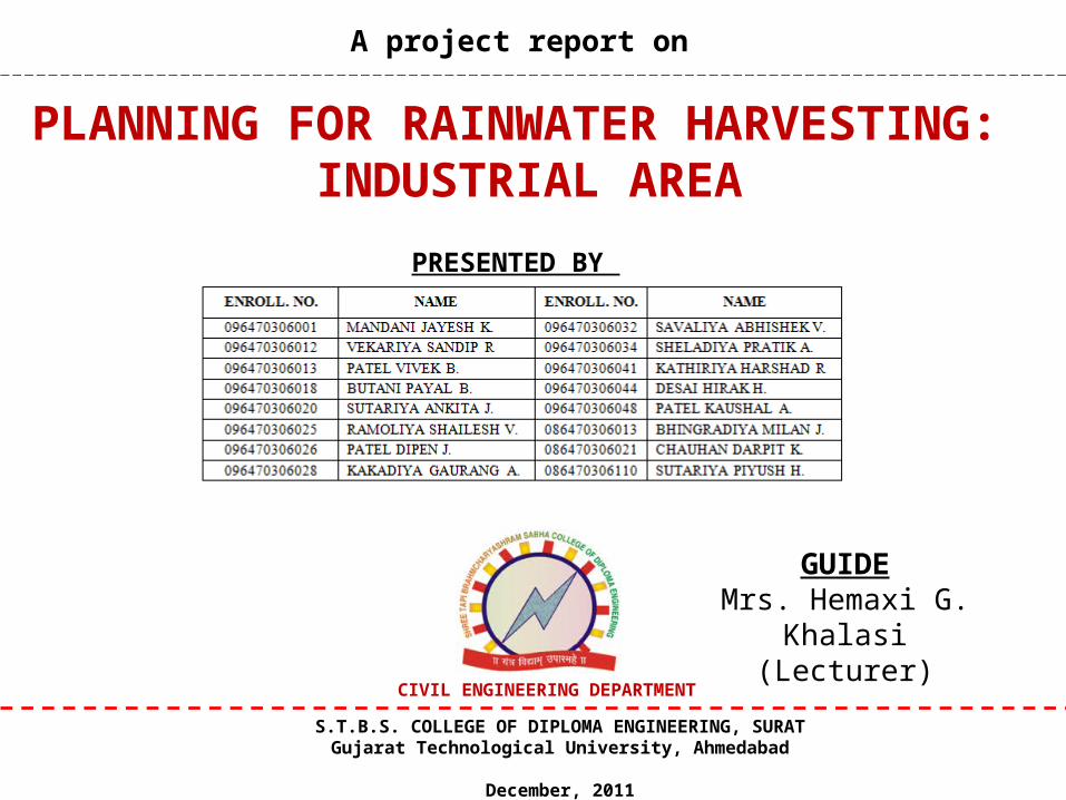
PLANNING FOR RAINWATER HARVESTING: INDUSTRIAL AREA
A project report on
GUIDEMrs. Hemaxi G. Khalasi
(Lecturer)
PRESENTED BY
S.T.B.S. COLLEGE OF DIPLOMA ENGINEERING, SURATGujarat Technological University, Ahmedabad
December, 2011
CIVIL ENGINEERING DEPARTMENT
2
CONTENTS• INTRODUCTION
• LITERATURE REVIEW
• RAINWATER HARVESTING SYSTEM
• STUDY AREA PROFILE
• DATA COLLECTION AND ANALYSIS
• RWH SYSTEM DESIGN
• CONCLUSIONS
• REFERENCES

INTRODUCTION
3
4
General
• Millions of people throughout the world do not have access to clean water for domestic purposes.
• Rainwater harvesting (RWH) has thus regained its importance as a valuable alternative or supplementary water resource.
• People collect and store rainwater in buckets, tanks, ponds and wells.
• Rainwater harvesting is a simple low-cost technique that requires minimum specific expertise or knowledge and offers many benefits.
5
Research definition & Objectives
Water harvesting in its broadest sense can be defined as the collection of run-off rainwater for domestic water supply, agriculture and environmental management.
Following are the main objectives of the study.
• To study the techniques of R.W.H. in developed & developing nation.
• To conduct field survey in surat city , where R.W.H. techniques is introduced.
• To design proposals for the rise in Ground Water Table (GWT) and used rain water in industrial area at Surat city.
• To prepare working modal based on design.

6
Need for rainwater harvesting
• Due to pollution of both groundwater and surface waters, and the overall increased demand for water resources is increase.
• Therefore they have to turn to alternative or ‘new’ resources
like rainwater harvesting (RWH).
• Rainwater harvesting has been used for ages and examples can be found in all the great civilizations throughout history.
• The technology can be very simple or complex depending on the specific local circumstances.
• larger sub-surface and surface tanks are used for collecting larger amounts of rainwater.
7
Identifying Problem
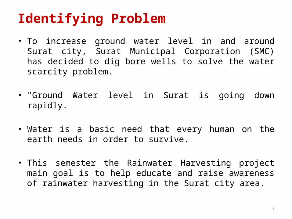
• To increase ground water level in and around Surat city, Surat Municipal Corporation (SMC) has decided to dig bore wells to solve the water scarcity problem.
• "Ground water level in Surat is going down rapidly.”
• Water is a basic need that every human on the earth needs in order to survive.
• This semester the Rainwater Harvesting project main goal is to help educate and raise awareness of rainwater harvesting in the Surat city area.
8
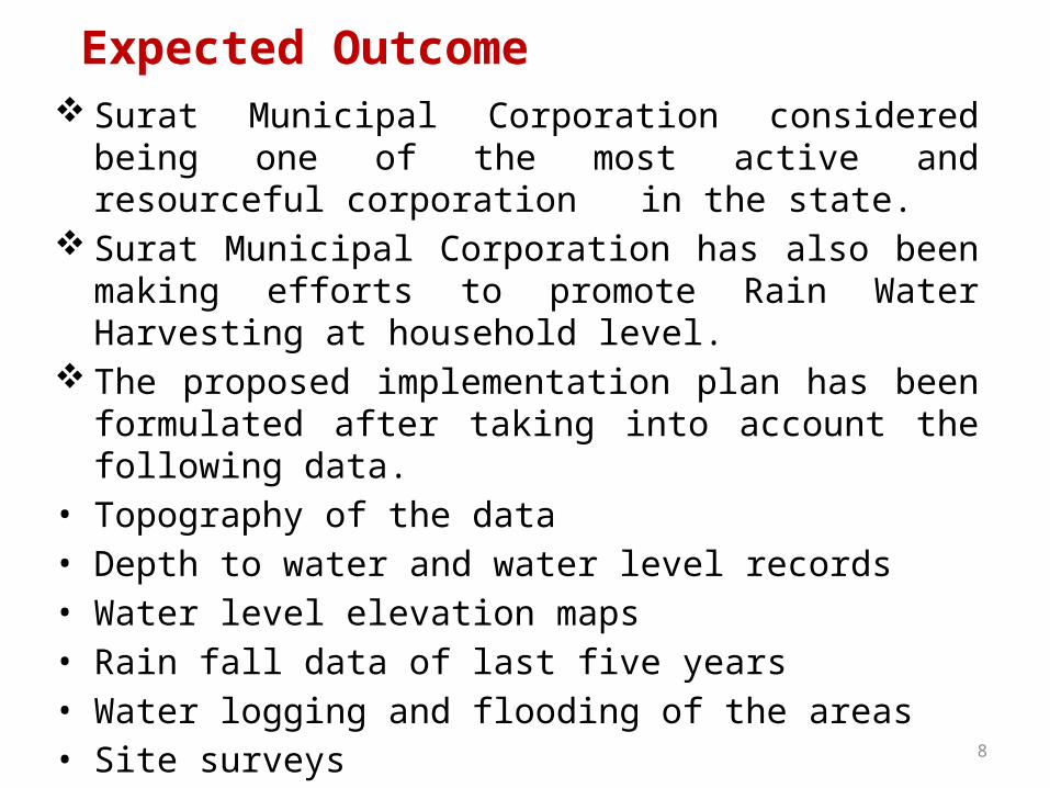
Expected Outcome Surat Municipal Corporation considered being one of the most
active and resourceful corporation in the state. Surat Municipal Corporation has also been making efforts to
promote Rain Water Harvesting at household level. The proposed implementation plan has been formulated after
taking into account the following data.• Topography of the data• Depth to water and water level records• Water level elevation maps• Rain fall data of last five years• Water logging and flooding of the areas• Site surveys• Geology and hydrology of area
9
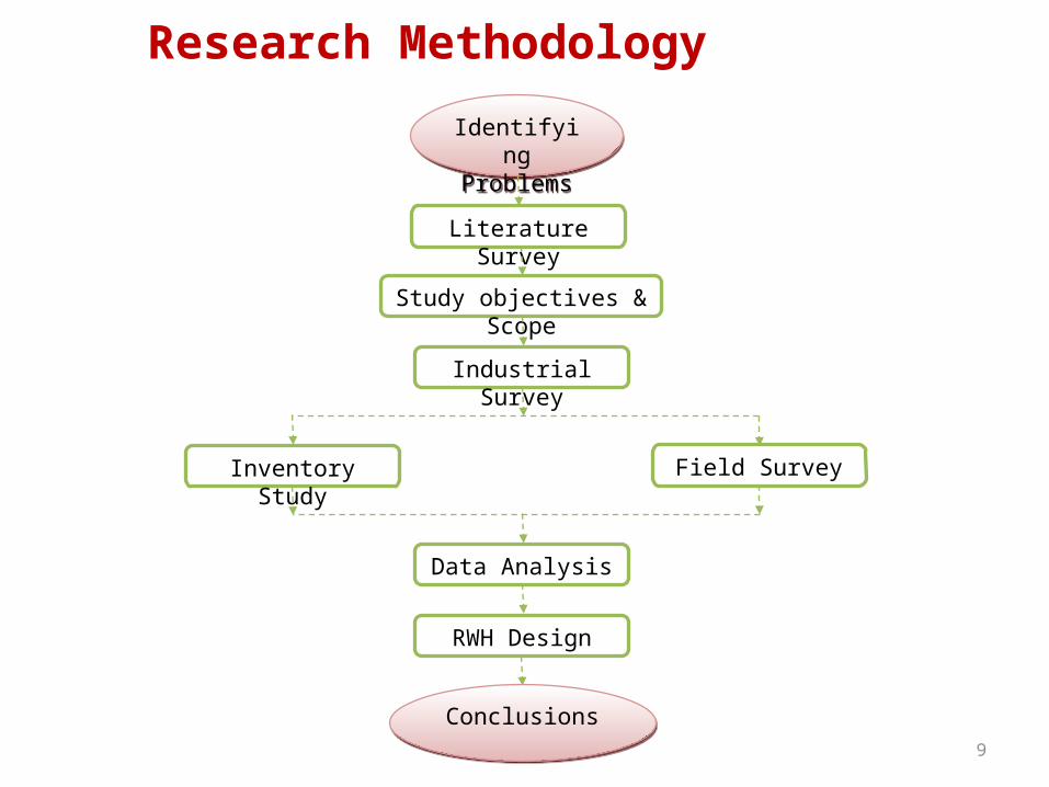
Research Methodology
Field Survey
Literature Survey
Identifying Problems
Identifying Problems
Study objectives & Scope
Industrial Survey
Inventory Study
Data Analysis
RWH Design
ConclusionsConclusions

LITERATURE REVIEW
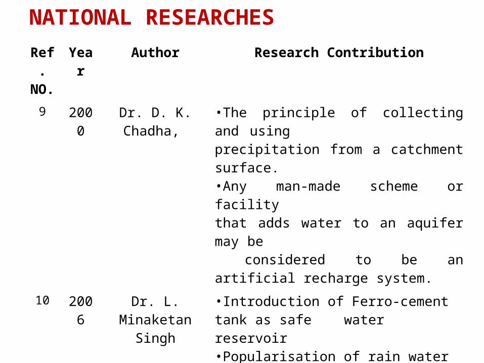
NATIONAL RESEARCHES
Ref. NO.
Year Author Research Contribution
9 2000 Dr. D. K. Chadha, •The principle of collecting and using precipitation from a catchment surface.•Any man-made scheme or facilitythat adds water to an aquifer may be considered to be an artificial recharge system.
10 2006 Dr. L. Minaketan Singh
•Introduction of Ferro-cement tank as safe water reservoir•Popularisation of rain water harvesting techniques in the state.
11 2011 Dr. S.C. Dhiman •To maintain sustainability of ground water resources artificial recharge to ground water is being practiced.
22 2001 S. Vishvanath •Water harvesting is also defined as the process of collecting and storing water from an area that has been treated to increase precipitation runoff.
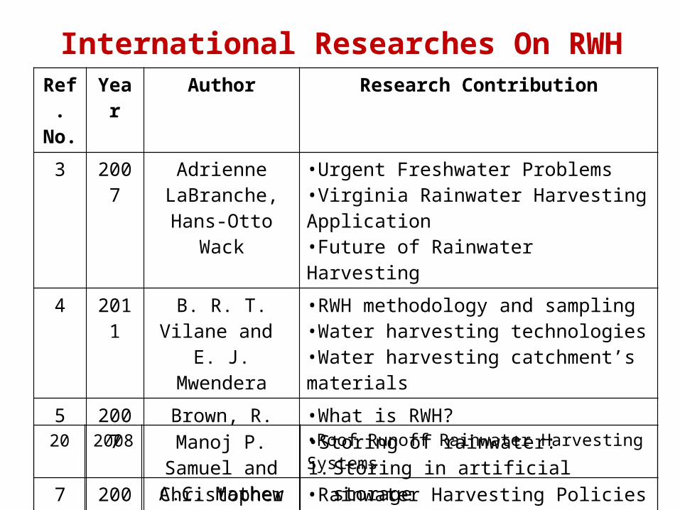
International Researches On RWHRef. No.
Year Author Research Contribution
3 2007 Adrienne LaBranche, Hans-
Otto Wack
•Urgent Freshwater Problems•Virginia Rainwater Harvesting Application•Future of Rainwater Harvesting
4 2011 B. R. T. Vilane and
E. J. Mwendera
•RWH methodology and sampling•Water harvesting technologies•Water harvesting catchment’s materials
5 2007 Brown, R. •What is RWH?•Roof Runoff Rainwater Harvesting Systems
7 2008 Christopher Kloss •Rainwater Harvesting Policies•Reduces erosion in urban environments
8 2005 Dr. Hari J. Krishna
•Water Balance and System Sizing•Rainwater Harvesting Guidelines
20 2008 Manoj P. Samuel and A.C. Mathew
•Storing of rainwater:1. Storing in artificial storage2. In the soil media groundwater
RAINWATER HARVESTING SYSTEM
RAINWATER HARVESTING SYSTEM
• As the Centre for Science and Environment, Delhi (India) puts it ‘CATCH WATER WHERE IT FALLS’ would be a good definition of rainwater harvesting.
• The process of rainwater harvesting would encompass catching rainwater, directing it to an appropriate location, filtering it if required and storing it for use.
• A number of alternative technologies are available for rooftop harvesting and storage to suit the varying situations and the budgets.
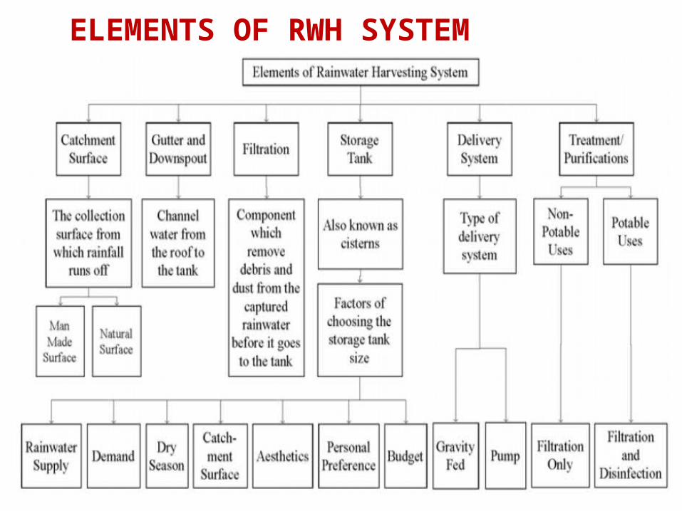
ELEMENTS OF RWH SYSTEM
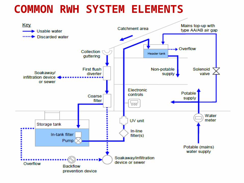
COMMON RWH SYSTEM ELEMENTS
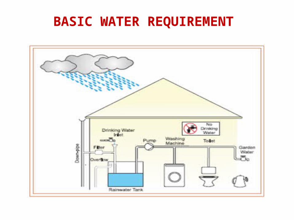
BASIC WATER REQUIREMENT
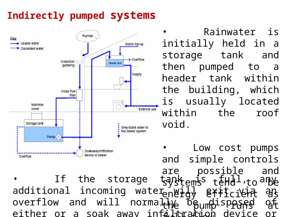
Indirectly pumped systems • Rainwater is initially held in a storage tank and then pumped to a header tank within the building, which is usually located within the roof void.
• Low cost pumps and simple controls are possible and systems tend to be energy efficient as the pump runs at full flow.
• If the storage tank is full, any additional incoming water will exit via an overflow and will normally be disposed of either or a soak away infiltration device or sewer.
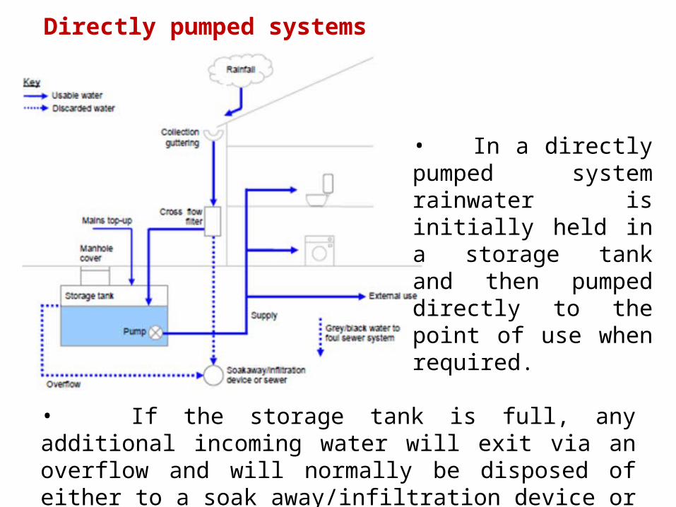
Directly pumped systems
• In a directly pumped system rainwater is initially held in a storage tank and then pumped directly to the point of use when required.
• If the storage tank is full, any additional incoming water will exit via an overflow and will normally be disposed of either to a soak away/infiltration device or sewer.

Gravity fed systems• The main advantages of gravity fed systems are that they do not require a pump or electrical supply as is the case with the direct and indirect versions.
• The main disadvantages are that the water pressure is likely to be less than that of the main supply.
• Gravity fed systems differs from the direct and indirect variants primarily in that the main storage tank is located within the roof void of the building.

STUDY AREA PROFILE
• The development of ground water in different areas of the country has not been uniform.
• Water requirement for industries is more.
• Industries require water for processing, cooling, boiler feed and other miscellaneous uses such as washing, maintenance of yards and domestic requirement in townships.
• Main source of water for Surat is the river Tapi flowing through the city.
General
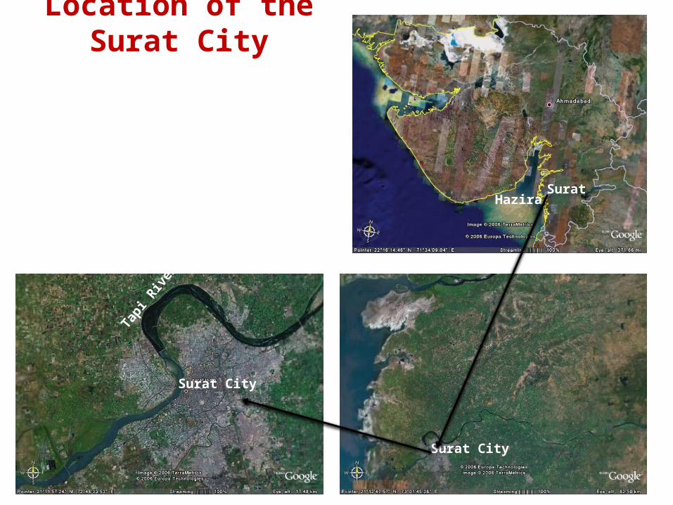
Location of the Surat City
HaziraSurat
Surat City
Tapi R
iver
Surat City
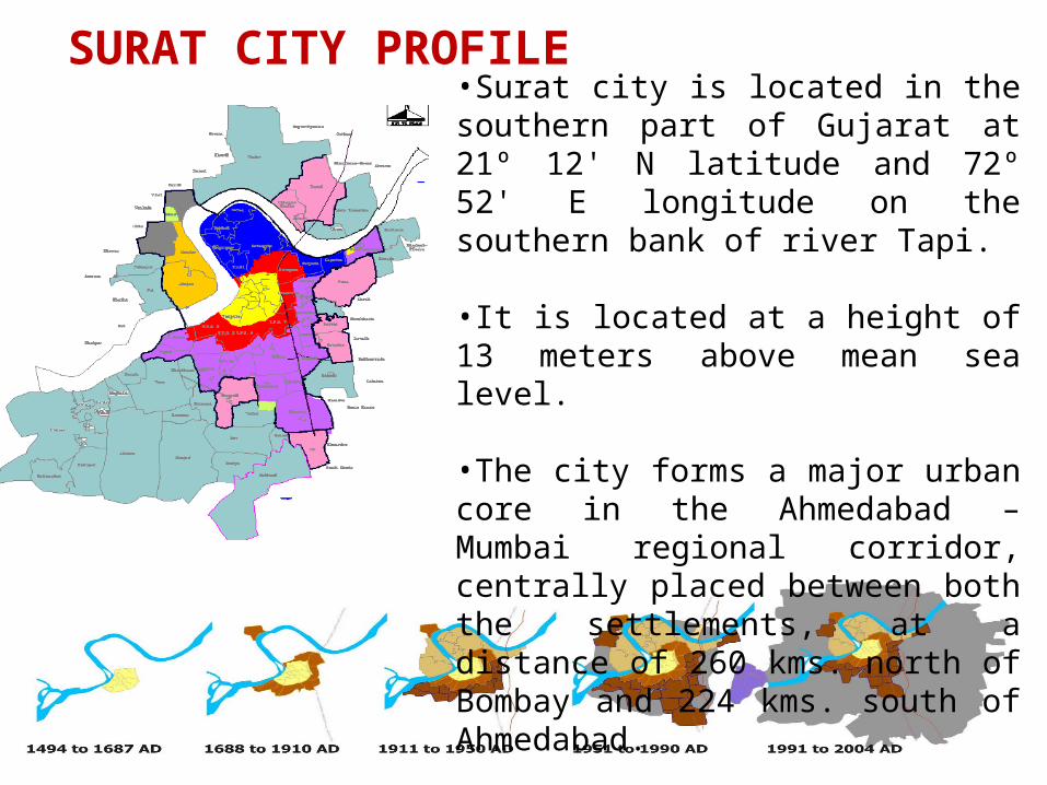
SURAT CITY PROFILE•Surat city is located in the southern part of Gujarat at 21º 12' N latitude and 72º 52' E longitude on the southern bank of river Tapi.
•It is located at a height of 13 meters above mean sea level.
•The city forms a major urban core in the Ahmedabad – Mumbai regional corridor, centrally placed between both the settlements, at a distance of 260 kms. north of Bombay and 224 kms. south of Ahmedabad.
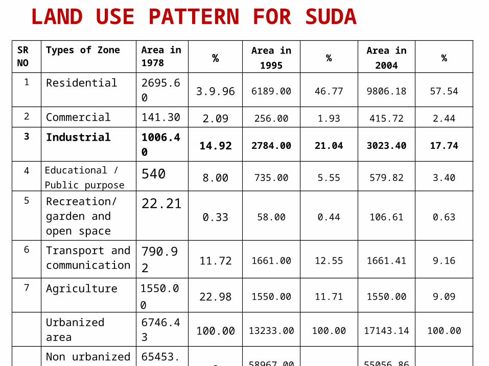
LAND USE PATTERN FOR SUDASR NO
Types of Zone Area in 1978 %
Area in 1995
%Area in
2004%
1 Residential 2695.60 3.9.96 6189.00 46.77 9806.18 57.54
2 Commercial 141.30 2.09 256.00 1.93 415.72 2.44
3 Industrial 1006.40 14.92 2784.00 21.04 3023.40 17.74
4 Educational / Public purpose
540 8.00 735.00 5.55 579.82 3.40
5 Recreation/ garden and open space
22.210.33 58.00 0.44 106.61 0.63
6 Transport and communication
790.9211.72 1661.00 12.55 1661.41 9.16
7 Agriculture 1550.00 22.98 1550.00 11.71 1550.00 9.09
Urbanized area 6746.43 100.00 13233.00 100.00 17143.14 100.00
Non urbanized area 65453.57- 58967.00 55056.86
Total 72200.00 72200.00 72200.00
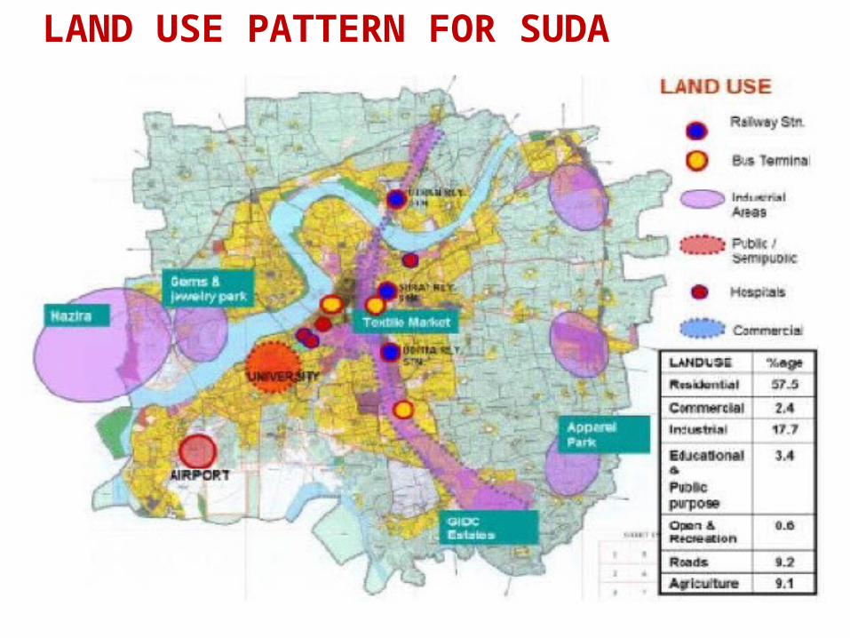
LAND USE PATTERN FOR SUDA
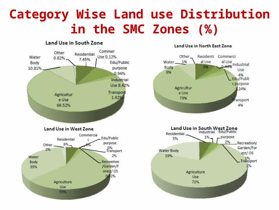
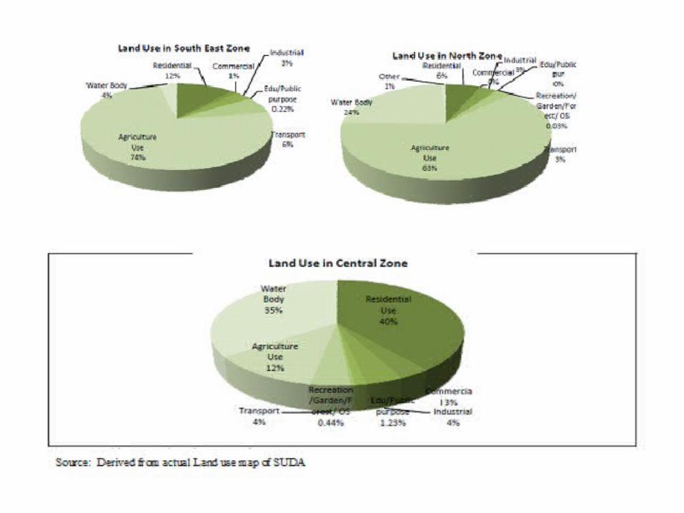
Category Wise Land use Distribution in the SMC Zones (%)

SOURCES OF WATER SUPPLY• Surface Water Sources Main source of water for the city has been the river Tapi since centuries. Surat city has grown at a very spur growth rate so to harness the river water for flood
control, agriculture, power generation, domestic and industrial purposes the Kakarapar weir, the Ukai dam and Singanpore weir were constructed in the year 1954, 1972 and 1995 respectively.
Daily average water supply in SMC
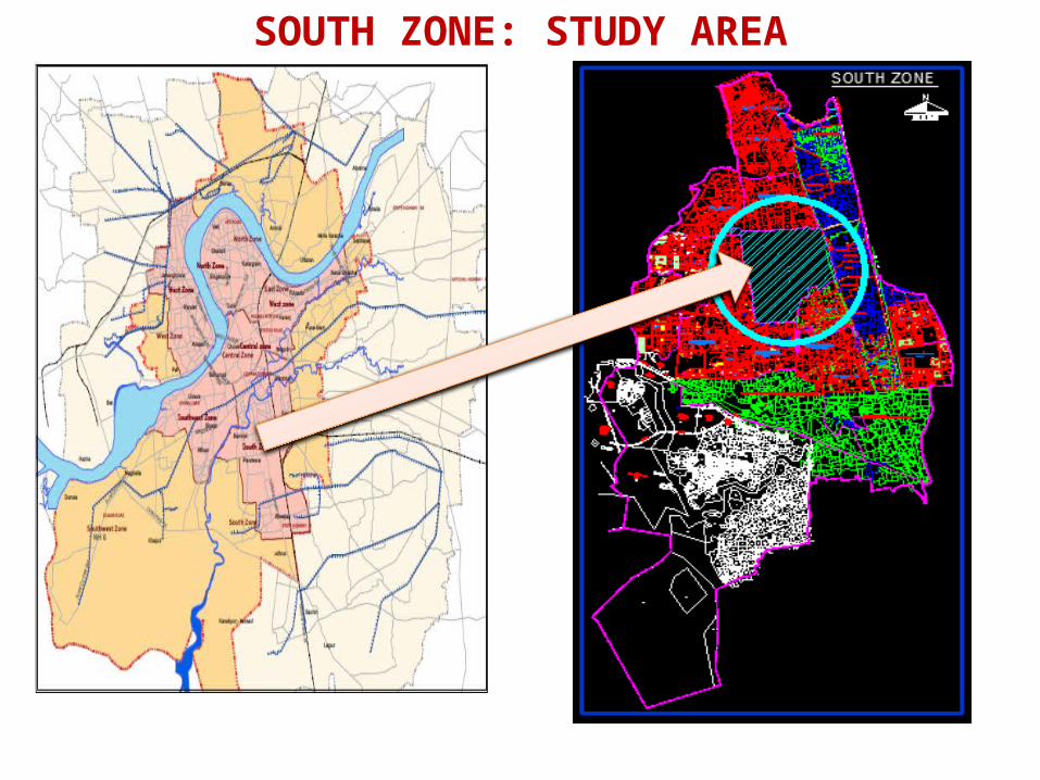
SOUTH ZONE: STUDY AREA

31
DATA COLLECTION AND ANALYSIS
32
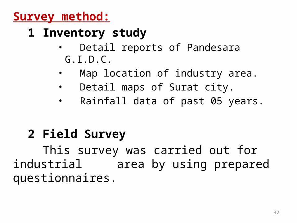
Survey method:
1 Inventory study• Detail reports of Pandesara G.I.D.C.• Map location of industry area.• Detail maps of Surat city.• Rainfall data of past 05 years.
2 Field Survey
This survey was carried out for industrial area by using prepared questionnaires.
33
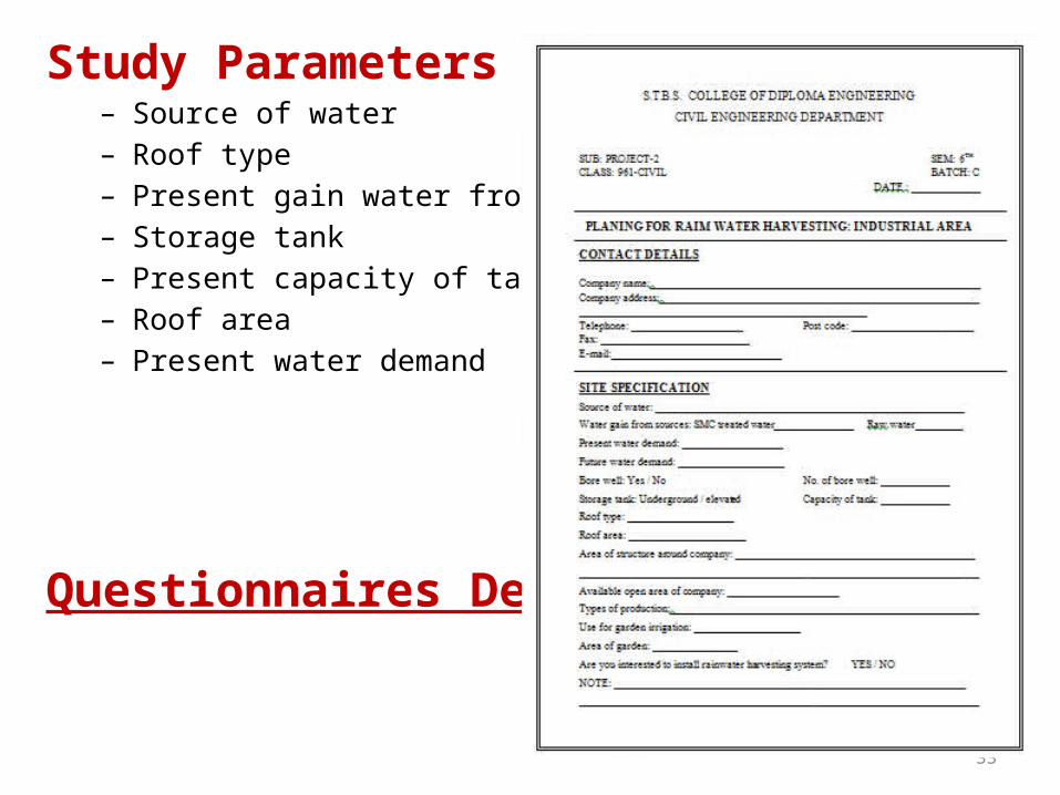
Study Parameters– Source of water – Roof type– Present gain water from SMC– Storage tank– Present capacity of tank– Roof area– Present water demand
Questionnaires Design

34
DATA ANALYSIS
Source of water
SOURCE OF WATER
SR NO SOURCE SURVEY %
1 SMC 86 96.63
2 BORE WELL 1 1.12
3 BOTH 2 2.25
TOTAL 89 100.00
97%
1% 2%
SOURCE OF WATER
SMCBORE WELLBOTH
35
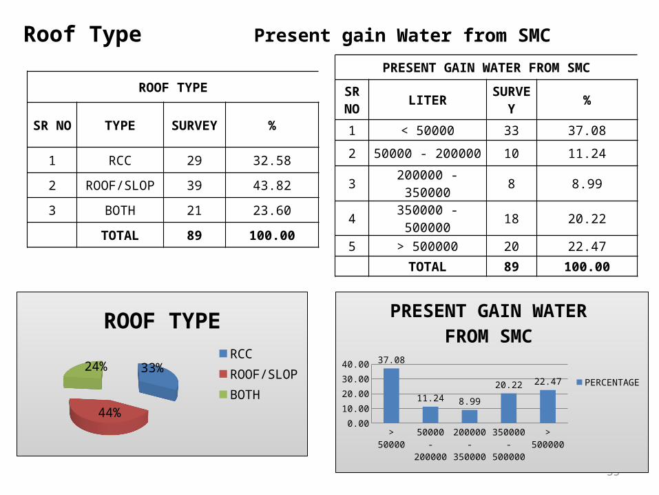
Roof Type Present gain Water from SMC
ROOF TYPE
SR NO TYPE SURVEY %
1 RCC 29 32.58
2 ROOF/SLOP 39 43.82
3 BOTH 21 23.60
TOTAL 89 100.00
33%
44%
24%
ROOF TYPE
RCCROOF/SLOPBOTH
PRESENT GAIN WATER FROM SMC
SR NO LITER SURV
EY %
1 < 50000 33 37.08
2 50000 - 200000 10 11.24
3 200000 - 350000 8 8.99
4 350000 - 500000 18 20.22
5 > 500000 20 22.47
TOTAL 89 100.00
> 50000 50000 - 200000
200000 - 350000
350000 - 500000
> 5000000.005.00
10.0015.0020.0025.0030.0035.0040.00 37.08
11.24 8.99
20.22 22.47
PRESENT GAIN WATER FROM SMC
PERCENTAGE
36
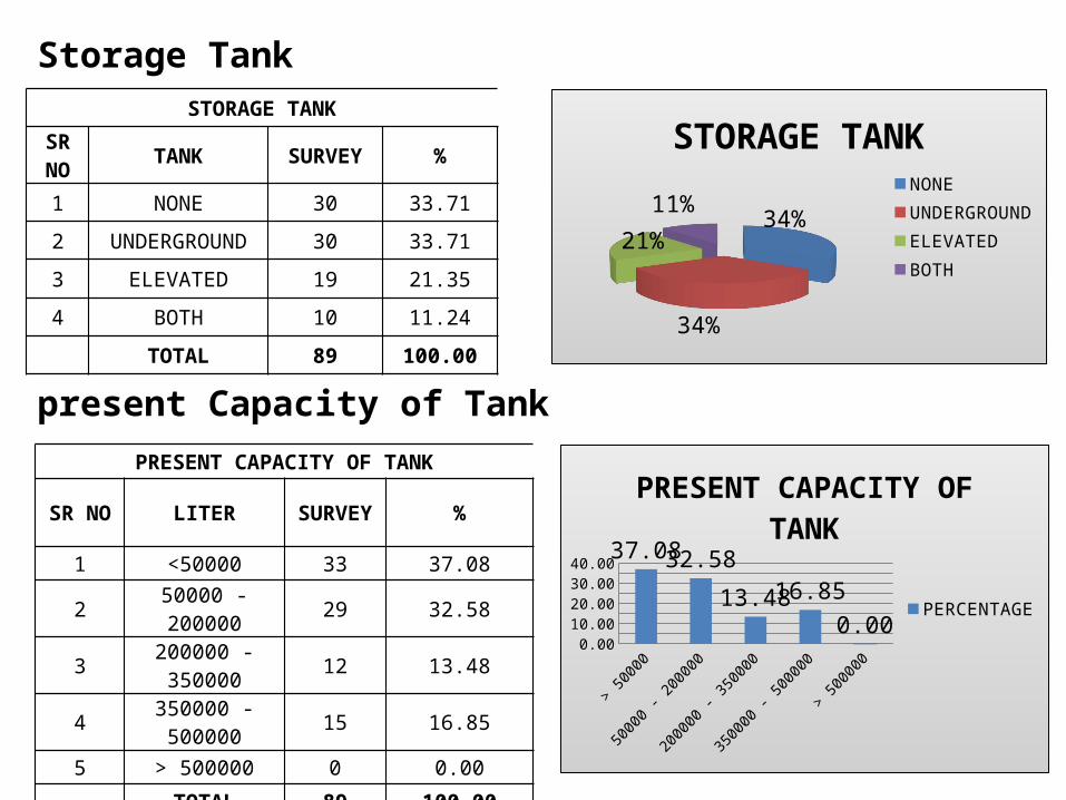
Storage Tank
present Capacity of Tank
STORAGE TANK
SR NO TANK SURVEY %
1 NONE 30 33.71
2 UNDERGROUND 30 33.71
3 ELEVATED 19 21.35
4 BOTH 10 11.24
TOTAL 89 100.00
34%
34%
21%11%
STORAGE TANK
NONEUNDERGROUNDELEVATEDBOTH
PRESENT CAPACITY OF TANK
SR NO LITER SURVEY %
1 <50000 33 37.08
2 50000 - 200000 29 32.58
3 200000 - 350000 12 13.48
4 350000 - 500000 15 16.85
5 > 500000 0 0.00
TOTAL 89 100.00> 50000 50000 -
200000200000 - 350000
350000 - 500000
> 5000000.00
5.00
10.00
15.00
20.00
25.00
30.00
35.00
40.00 37.0832.58
13.4816.85
0.00
PRESENT CAPACITY OF TANK
PERCENTAGE
37
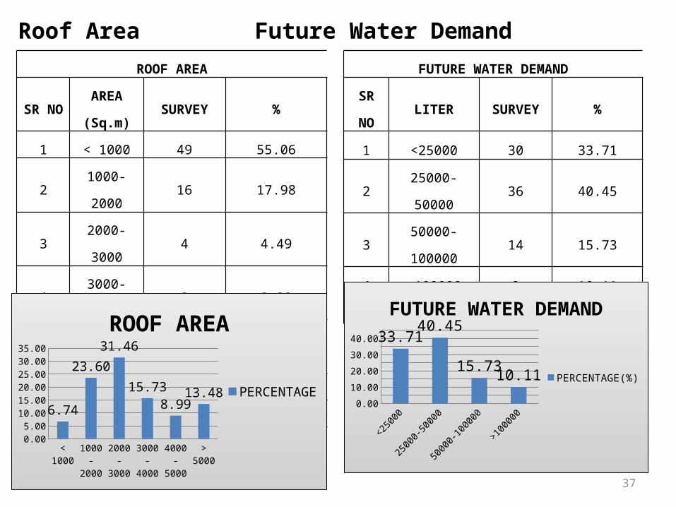
Roof Area Future Water Demand
ROOF AREA
SR NOAREA
(Sq.m)SURVEY %
1 < 1000 49 55.06
2 1000-2000 16 17.98
3 2000-3000 4 4.49
4 3000-4000 8 8.99
5 4000-5000 5 5.62
6 > 5000 7 7.87
TOTAL 89 100.00
< 1000 1000-2000
2000-3000
3000-4000
4000-5000
> 50000.00
5.00
10.00
15.00
20.00
25.00
30.00
35.00
6.74
23.60
31.46
15.73
8.9913.48
ROOF AREA
PERCENTAGE
FUTURE WATER DEMAND
SR
NOLITER SURVEY %
1 <25000 30 33.71
2 25000-50000 36 40.45
3 50000-100000 14 15.73
4 >100000 9 10.11
TOTAL 89 100.00
<25000 25000-50000
50000-100000
>1000000.005.00
10.0015.0020.0025.0030.0035.0040.0045.00
33.7140.45
15.7310.11
FUTURE WATER DEMAND
PERCENTAGE(%)
38
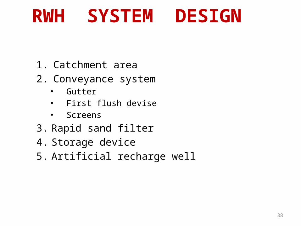
RWH SYSTEM DESIGN
1. Catchment area
2. Conveyance system• Gutter• First flush devise• Screens
3. Rapid sand filter
4. Storage device
5. Artificial recharge well
39
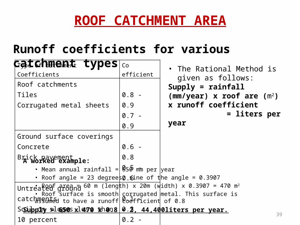
ROOF CATCHMENT AREA
Runoff coefficients for various catchment typesType of catchment Coefficients Co efficient
Roof catchmentsTilesCorrugated metal sheets
0.8 - 0.90.7 - 0.9
Ground surface coveringsConcreteBrick pavement
0.6 - 0.80.5 - 0.6
Untreated ground catchmentsSoil on slopes less than 10 percentRocky natural catchments
0.1 - 0.30.2 - 0.5
• The Rational Method is given as follows:
Supply = rainfall (mm/year) x roof are (m2) x runoff coefficient = liters per year
A worked example:• Mean annual rainfall = 650 mm per year
• Roof angle = 23 degrees; sine of the angle = 0.3907
• Roof area = 60 m (length) x 20m (width) x 0.3907 = 470 m2
• Roof surface is smooth corrugated metal. This surface is assumed to have a runoff coefficient of 0.8
Supply = 650 x 470 x 0.8 = 2, 44,400liters per year.

40
THE CONVEYANCE SYSTEMGutters
Roof area (m2) served
by one gutter
Gutter width(mm)
Minimum downpipediameter
(mm)
17 60 4025 70 5034 80 5046 90 6366 100 63
128 125 75208 150 90
Sizing gutters and down-pipes for RWH systems
The size (width) of the gutters should be chosen based on the roof section area. Design length of Roof is 60 meter. Select gutter size based on 1 centimeter per meter or 1/8 inch per foot. So adopt diameter of gutter pipe is 60 centimeter.
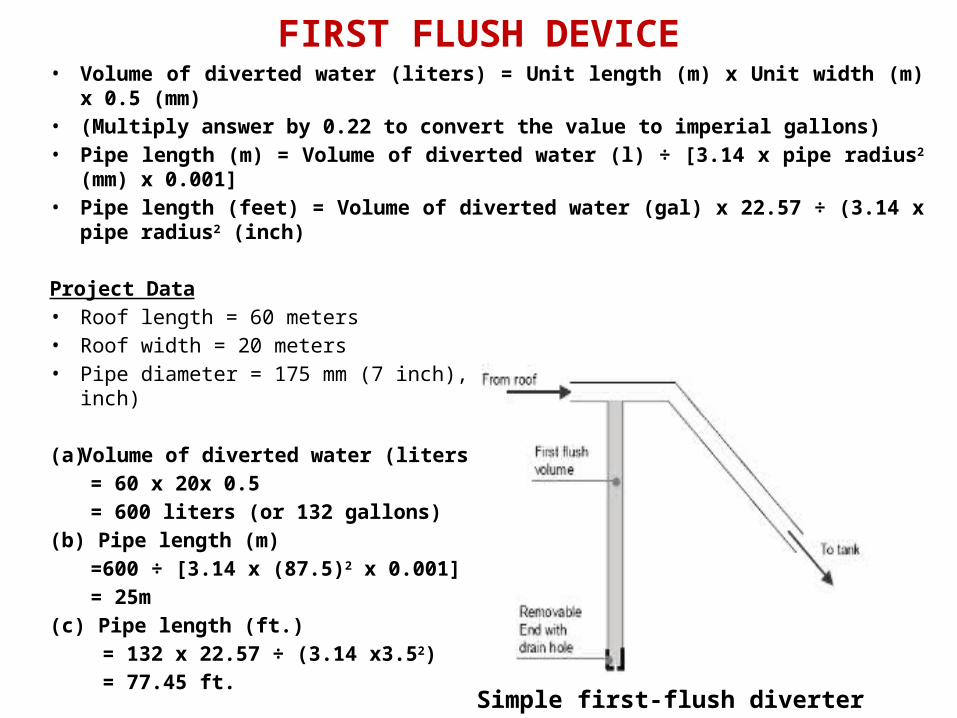
FIRST FLUSH DEVICE• Volume of diverted water (liters) = Unit length (m) x Unit width (m) x 0.5 (mm)• (Multiply answer by 0.22 to convert the value to imperial gallons) • Pipe length (m) = Volume of diverted water (l) ÷ [3.14 x pipe radius2 (mm) x 0.001]• Pipe length (feet) = Volume of diverted water (gal) x 22.57 ÷ (3.14 x pipe radius2
(inch)
Project Data• Roof length = 60 meters• Roof width = 20 meters• Pipe diameter = 175 mm (7 inch), therefore radius = 87.5 mm (3.5 inch)
(a) Volume of diverted water (liters)
= 60 x 20x 0.5
= 600 liters (or 132 gallons)
(b) Pipe length (m)
=600 ÷ [3.14 x (87.5)2 x 0.001]
= 25m
(c) Pipe length (ft.)
= 132 x 22.57 ÷ (3.14 x3.52)
= 77.45 ft.Simple first-flush diverter
42
Screens:
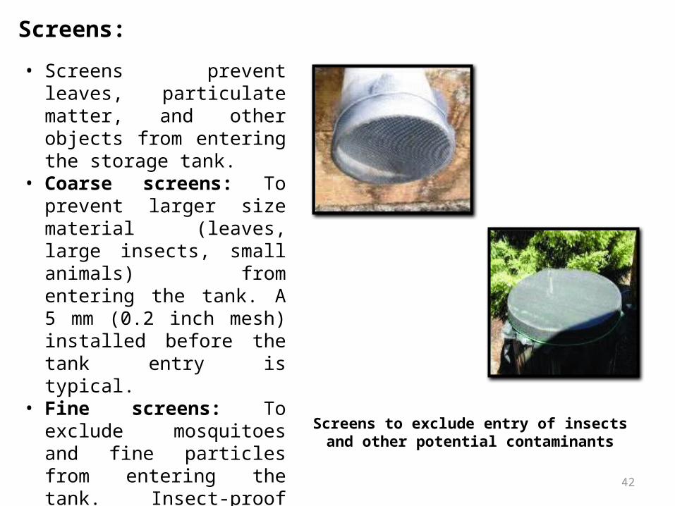
Screens to exclude entry of insects and other potential contaminants
• Screens prevent leaves, particulate matter, and other objects from entering the storage tank.
• Coarse screens: To prevent larger size material (leaves, large insects, small animals) from entering the tank. A 5 mm (0.2 inch mesh) installed before the tank entry is typical.
• Fine screens: To exclude mosquitoes and fine particles from entering the tank. Insect-proof mesh or strong standard cotton/polypropylene filters installed at the inlet and outlet of the tank is recommended.
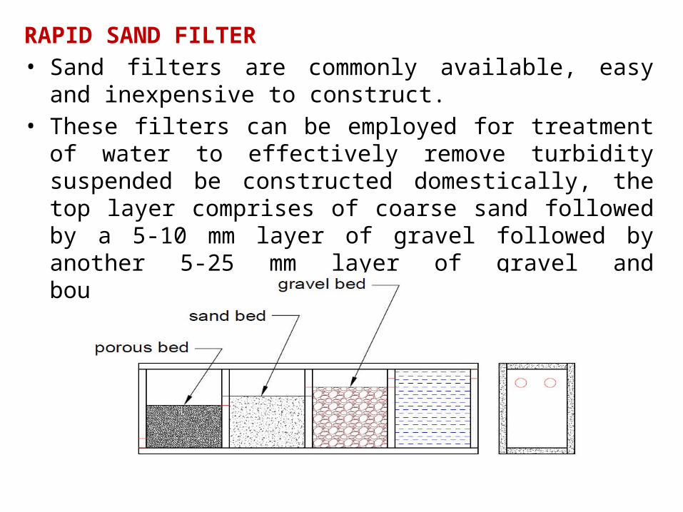
RAPID SAND FILTER• Sand filters are commonly available, easy and inexpensive to
construct. • These filters can be employed for treatment of water to
effectively remove turbidity suspended be constructed domestically, the top layer comprises of coarse sand followed by a 5-10 mm layer of gravel followed by another 5-25 mm layer of gravel and boulders.
44
DESIGNS OF TANKS
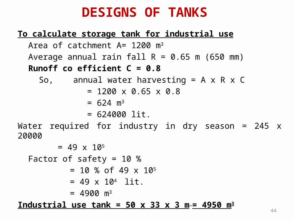
To calculate storage tank for industrial use
Area of catchment A= 1200 m3
Average annual rain fall R = 0.65 m (650 mm)
Runoff co efficient C = 0.8
So, annual water harvesting = A x R x C
= 1200 x 0.65 x 0.8
= 624 m3
= 624000 lit.
Water required for industry in dry season = 245 x 20000
= 49 x 105
Factor of safety = 10 %
= 10 % of 49 x 105
= 49 x 104 lit.
= 4900 m3
Industrial use tank = 50 x 33 x 3 m = 4950 m3
45
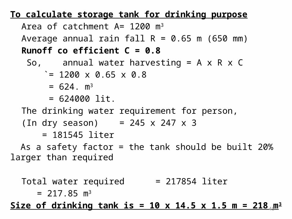
To calculate storage tank for drinking purpose
Area of catchment A= 1200 m3
Average annual rain fall R = 0.65 m (650 mm)
Runoff co efficient C = 0.8
So, annual water harvesting = A x R x C
`= 1200 x 0.65 x 0.8
= 624. m3
= 624000 lit.
The drinking water requirement for person,
(In dry season) = 245 x 247 x 3
= 181545 liter
As a safety factor = the tank should be built 20% larger than required
Total water required = 217854 liter
= 217.85 m3
Size of drinking tank is = 10 x 14.5 x 1.5 m = 218 m3
46
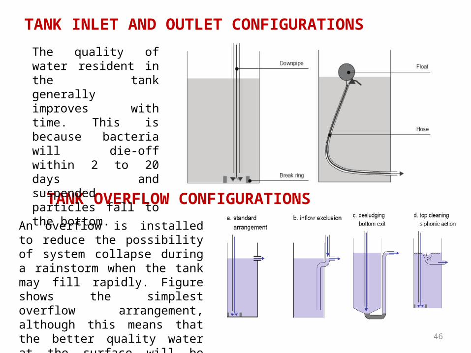
TANK INLET AND OUTLET CONFIGURATIONS
TANK OVERFLOW CONFIGURATIONS
The quality of water resident in the tank generally improves with time. This is because bacteria will die-off within 2 to 20 days and suspended particles fall to the bottom.
An overflow is installed to reduce the possibility of system collapse during a rainstorm when the tank may fill rapidly. Figure shows the simplest overflow arrangement, although this means that the better quality water at the surface will be lost to the outflow
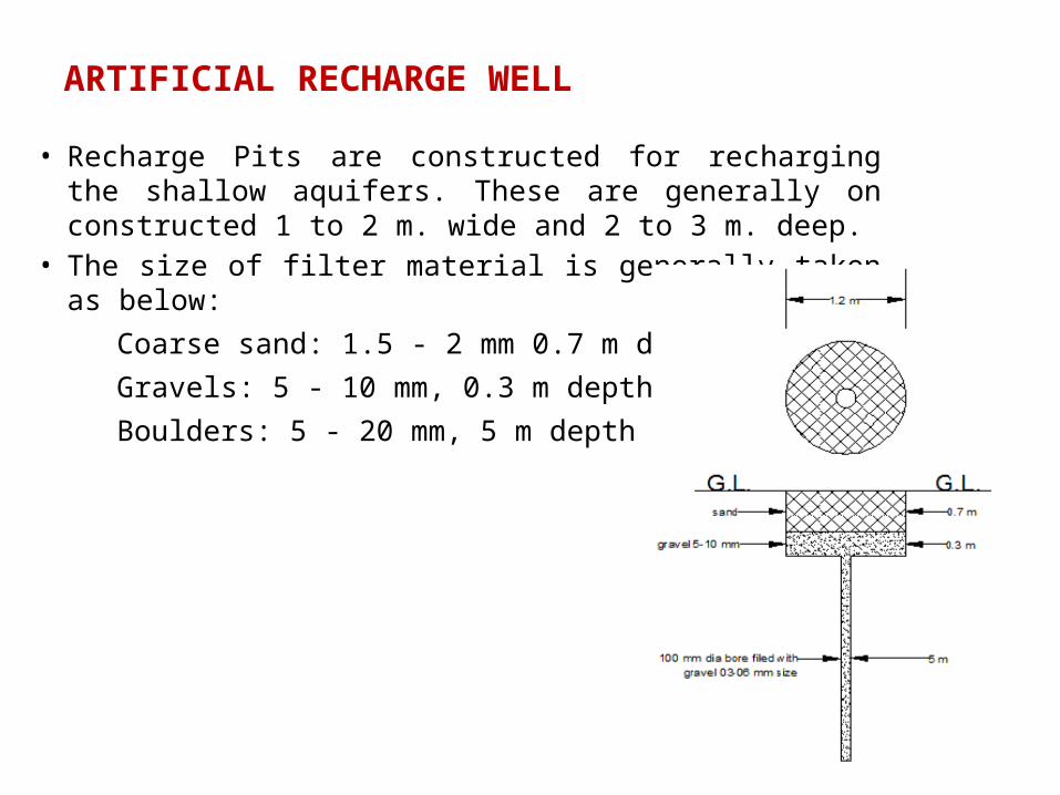
ARTIFICIAL RECHARGE WELL
• Recharge Pits are constructed for recharging the shallow aquifers. These are generally on constructed 1 to 2 m. wide and 2 to 3 m. deep.
• The size of filter material is generally taken as below: Coarse sand: 1.5 - 2 mm 0.7 m depth Gravels: 5 - 10 mm, 0.3 m depthBoulders: 5 - 20 mm, 5 m depth

48
CONCLUSIONS
• Major parts of our country have been facing continuous failure of monsoon and consequent deficit of rainfall over the last few years. Also, due to ever increasing population of India, the use of ground water has increased drastically leading to constant depletion of ground water level causing the wells and tube wells to dry up.
• In Surat city river tapi is the main source of drinking water because underground water level depth is so high. In particularly in industrial area water demand is so high compare to availability of water through Surat Municipal Corporation.
• According to this crisis this research is help to fulfill water demand and to uplift underground water level. Rain water harvesting is the best solution for underground water recharging and water is used in industrial production work.

REFERENCES• A planning guides for Tanzania, (2000) ‘Rainwater Harvesting for Natural Resources Management’, Regional Land Management Unit,
RELMA/Sida, ICRAF House, Gigiri P. O. Box 63403, Nairobi, Kenya.
• A Contractor’s guide,(2005) ‘Domestic Rainwater Harvesting in Queensland’, Helping Queenslanders Build Better.
• Adrienne LaBranche, Hans-Otto Wack,(2007) ‘Virginia Rainwater Harvesting Manual’, the Cabell Brand Center, Salem, VA.
• B. R. T. Vilane and E. J. Mwendera, (2011) ‘An inventory of rainwater harvesting technologies in Swaziland’, African Journal of Agricultural Research Vol. 6(6), pp. 1313-1321.
• Brown, R. (2007) ‘Rainwater and Grey Water: Technical and economic feasibility’, Draft Report. BSRIA Ltd for the Market Transformation Programme.
• Che-Ani A.I and Shaari N, (2009) ‘Rainwater Harvesting as an Alternative Water Supply in the Future’, European Journal of Scientific Research, ISSN 1450-216X Vol.34 No.1 (2009), pp.132-140.
• Christopher Kloss, (2008) ‘Rainwater Harvesting Policies’, Municipal Handbook, Low Impact Development Center, EPA-833-F-08-010.
• Dr. Hari J. Krishna, (2005) ‘The Texas Manual on Rainwater Harvesting’, Texas Water Development Board, Austin
• Dr. D. K. Chadha, (2000) ‘Rain Water Harvesting and Artificial Recharge to Ground Water’, Central Ground Water Board Jamnagar House, Mansingh Road New Delhi-110011.
• Dr. L. Minaketan Singh, P.I., (2006) ‘Pilot Project on Rain Water Harvesting in Manipur Manipur Science & Technology Council Central Jail Road, Imphal - 795 001.
• Dr. S.C. Dhiman,(2011) ‘Rain Water and Artificial Recharge’, Central Ground Water Board, Ministry of Water Resources, New Delhi.

• Environment Agency, (2008) ‘Harvesting rainwater for domestic uses: an information guide’, Environment Agency, Rio House, Waterside Drive, Aztec West, Almondsbury, Bristol BS32 4UD.
• Fewkes, A. (2005) ‘The technology, design and utility of rainwater catchment systems’, In Water Demand Management Memon, FA and Butler, D (eds). IWA Publishing.
• Hassell, C. (2005) ‘Rainwater harvesting in the UK – a solution to increasing water shortages?’ Proceedings of the 9th International Conference on Rainwater Catchment Cistern Systems. Petrolina, Brazil.
• Janette Worm, Tim van Hattum, (2006) ‘Rainwater harvesting for domestic use’, Agromisa Foundation and CTA, Wageningen, The Netherlands.
• Kalyan Ray, (2005) ‘Rainwater Harvesting and Utilisation’, Settlements Programme (UN-HABITAT) Water, Sanitation and Infrastructure Branch P.O. Box. 30030, Nairobi, Kenya.
• Konig, Klaus W., (2008) ‘A Low impact architecture in Germany Cooling with Rainwater’, Architekturbüro, Jakob-Kessenring-Str. 38, 88662 Überlingen / Germany.
• Konig, K. W. (2001) ‘The Rainwater Technology Handbook: Rainwater Harvesting in building’, Wilo-Brain, Dortmund.
• Leggett, D. J., Brown, R., Brewer, D., Stanfield, G. and Holiday, E. (2001) ‘Rainwater and grey water use in buildings: Best practice guidance’, (C539). CIRIA, London.
• Manoj P. Samuel and A.C. Mathew, (2008) ‘Rejuvenation of Water Bodies by Adopting Rainwater Harvesting and Groundwater Recharging Practices in Catchment Area – A case study’, Proceedings of Taal2007: The 12th World Lake Conference 766 776.
• Patricia H. Waterfall, (2006) ‘Harvesting rainwater for landsace used’, Arizona Department of Water Resources, Tucson Active Management Area, 400 W. Congress, Suite 518, Tucson AZ 85701.
• S. Vishvanath, (2001) ‘Rainwater Harvesting in urban area’, 2646 main 6 block, BEL layout, Vidyaranyapura, Bangalore, 560 097.

52
THANK YOU