Embed Size (px)
Citation preview
4475 Alicia Lane
Cumming, GA 30028 (770) 889-2533
Rainharvest Systems, LLC www.rainharvest.com Tel: 770-889-2533/Fax: 770-889-2577
Rainflo IG Package Rainwater Harvesting System Maintenance
The RainFlo IG rainwater harvesting systems (700, 1000, 1250, and 1700 in ground systems)
have been designed to be as low maintenance as possible. The three main components that
will require periodic maintenance are the rainwater pre-filters, the rainwater storage tanks, the
rainwater pumping systems. The maintenance for these components is outlined below. For
additional instruction or questions contact RainHarvest Systems at (770) 889-2533.
Rainwater pre-filters:
Graf Optimax Pro Internal Rainwater Pre-Filter:
Description: The Graf Optimax Industrial filter is an in-tank, gravity fed screen filter that filters
rainwater prior to its entry into the storage tank to approximately 350 microns via a removable
stainless steel sieve insert.
Maintenance: It is recommended to remove the stainless steel screen filter insert from the
plastic filter housing and clean it at least once quarterly. The filter insert can be cleaned with a
water hose and soft bristle scrub brush by simply spraying the screen with water and scrubbing
the filter area with the scrub brush. The Optimax filters can also be outfitted with an optional
“self cleaning” spray head that is designed to spray the filter screen periodically to keep the
filter operating at its highest efficency level. Even when the optional spray head its utilized it is
recommended to clean the internal filter screen twice annually.
Rainwater Storage Tanks:
**ALWAYS OBSERVE OSHA GUIDELINES FOR ENTERING CONFINED SPACES
BEFORE AND DURING THE ENTRY AND SERVICE OF RAINWATER STORAGE
TANKS!! ALWAYS DISCONNECT ANY POWER LINES INSIDE THE RAINWATER
STORAGE TANKS BEFORE ENTERING THE TANKS!!**
Graf Carat S 1700 Gallon Below Ground Rainwater Storage Tank
4475 Alicia Lane
Cumming, GA 30028 (770) 889-2533
Rainharvest Systems, LLC www.rainharvest.com Tel: 770-889-2533/Fax: 770-889-2577
Description: Graf Carat S 700, 1000, 1250, or 1700 gallon below ground rainwater storage tank.
Made from polypropylene (Duralen). Dimensions vary by tank size.
Maintenance: It is recommended to clean Graf Carat rainwater harvesting tanks once every
three years. Cleaning the Carat tanks will require the tanks to be 95% emptied. When the
tanks are emptied it is recommended to agitate the sediment bed in the bottom of the tank so
that the sediment particles become suspended in the remaining water in the tank. Once the
particles are suspended the remaining water and sediment can be removed with a wet-dry
vacuum or a vacuum truck. The tanks do not need to be emptied during the winter months.
RainFlo Pump Systems:
RainFlo .75 or 1.25 HP submersible pumps
Description: 115V .75 or 1.25 submersible pump system with float switch for low water shut-
off. The RainFlo pump system utilizes a submersible pump with integral floating extractor, and
the RainFlo PC115A speed pump controller. The RainFlo pump system begins pumping water
automatically based on a drop in pressure in the pressurized water line on the discharge side of
the pump.
Maintenance:
**ALWAYS DISCONNECT THE POWER SUPPLY TO THE PUMP SYSTEM BEFORE
PERFORMING ANY SERVICE TO THE PUMP STATION OR BEFORE ENTERING THE
RAINWATER STORAGE TANKS!!**
The only maintenance required for the RainFlo pump is the winterization of the pressurized
water line from the pump to the irrigation/plumbing system. The pump does not need to be
removed from the tank during the winter, however if the pressurized water line from the pump
to the irrigation/plumbing system is buried within the freeze zone of the soil the owner will be
required to power off the pump/controller and drain the pressurized water line prior to the first
freeze of winter. The pressurized line should be drained back so that there is no water in the
water line above that of the water level in the tank. The pump needs to be removed from the
rainwater storage tank for service by disconnecting the discharge piping, and lifting the unit out
by the lift chain/rope that is attached to the Flow Inducer Pump Housing.
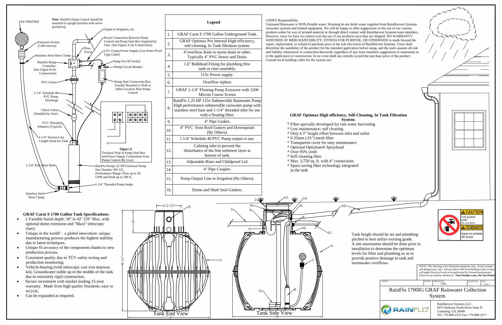
GRAF Optimax High efficiency, Self-Cleaning, In Tank FiltrationSystem:
* Filter specially developed for rain water harvesting * Low maintenance; self cleaning * Only 6.5” height offset between inlet and outlet * 0.35mm (.01") mesh filter * Transparent cover for easy maintenance * Optional Opticlean® Sprayhead * Over 95% yield * Self-cleaning filter * Max. 3,750 sq. ft. with 4" connections * Space saving filter technology integrated in the tank
Tank height should be set and plumbingpitched to best utilize existing grade.A site assessment should be done prior toinstallation to determine the optimumlevels for filter and plumbing so as toprovide positive drainage to tank andstormwater overflows.
Legend
1. GRAF Carat S 1700 Gallon Underground Tank.
2.GRAF Optimax Pro Internal High efficiency,
self-cleaning, In Tank filtration system.
3.4"overflow drain to storm drain or other.
Typically 4" PVC Sewer and Drain.
4. 1-14" Bulkhead Fitting for plumbing thru
tank or riser assembly.5. 115v Power supply.
6. Overflow siphon.
7. GRAF 1-1/4" Floating Pump Extractor with 1200Micron Coarse Screen
8.
RainFlo 1.25 HP 115v Submersible Rainwater PumpHigh performance submersible rainwater pump withstainless steel base and 1-1/4" threaded inlet for use
with a floating filter.
9. 4" Pipe Gasket.
10.4" PVC from Roof Gutters and Downspouts
(By Others).11. 1 1/4" Schedule 40 PVC Pump output to use.
12.Calming inlet to prevent the
disturbance of the fine sediment layer atbottom of tank.
13. Adjustable Riser and Childproof Lid.
14. 4" Pipe Coupler.
15. Pump Output Line to Irrigation (By Others).
16. Dome and Shaft Seal Gaskets.
Tank End View Tank Side View7'-4" 8'
8'-1
1"
2'
2'-2 1/2"
1.
3.
5.
7.
8.
9.9.
6.
12.
13.
9.
USER'S ResponsibilityUntreated Rainwater is NON-Potable water. Warning do not drink water supplied from RainHarvest Systemsrainwater systems and related equipment. We will be happy to offer suggestions on the use of our variousproducts either by way of printed material or through direct contact with RainHarvest Systems team members.However, since we have no control over the use of our products once they are shipped, NO WARRANTYWHETHER OF MERCHANTABILITY, FITNESS FOR PURPOSE, OR OTHERWISE is made beyond therepair, replacement, or refund of purchase price at the sole discretion of RainHarvest Systems. Users shalldetermine the suitability of the product for the intended application before using, and the users assume all riskand liability whatsoever in connection therewith, regardless of any team members suggestions or statements asto the application or construction. In no event shall any remedy exceed the purchase price of the product.Consult local building codes for the system use.
10.
2.
4.
15.
14.
GRAF Carat S 1700 Gallon Tank Specifications: 1.Variable burial depth: 30" to 42" (59" Max. with
optional dome extension and "Maxi" telescopicriser).
Unique in the world! – a global innovation: uniquemanufacturing process produces the highest stabilitydue to latest techniques.
Unique fit accuracy of the components thanks to newproduction process.
Consistent quality due to TÜV safety testing andproduction monitoring.
Vehicle-bearing (with telescopic cast iron manwaykit). Groundwater stable up to the middle of the tankdue to extremely rigid construction.
Secure investment with market leading 15-yearwarranty. Made from high quality Duralene; easy torecycle.
Can be expanded as required.
16.
16.
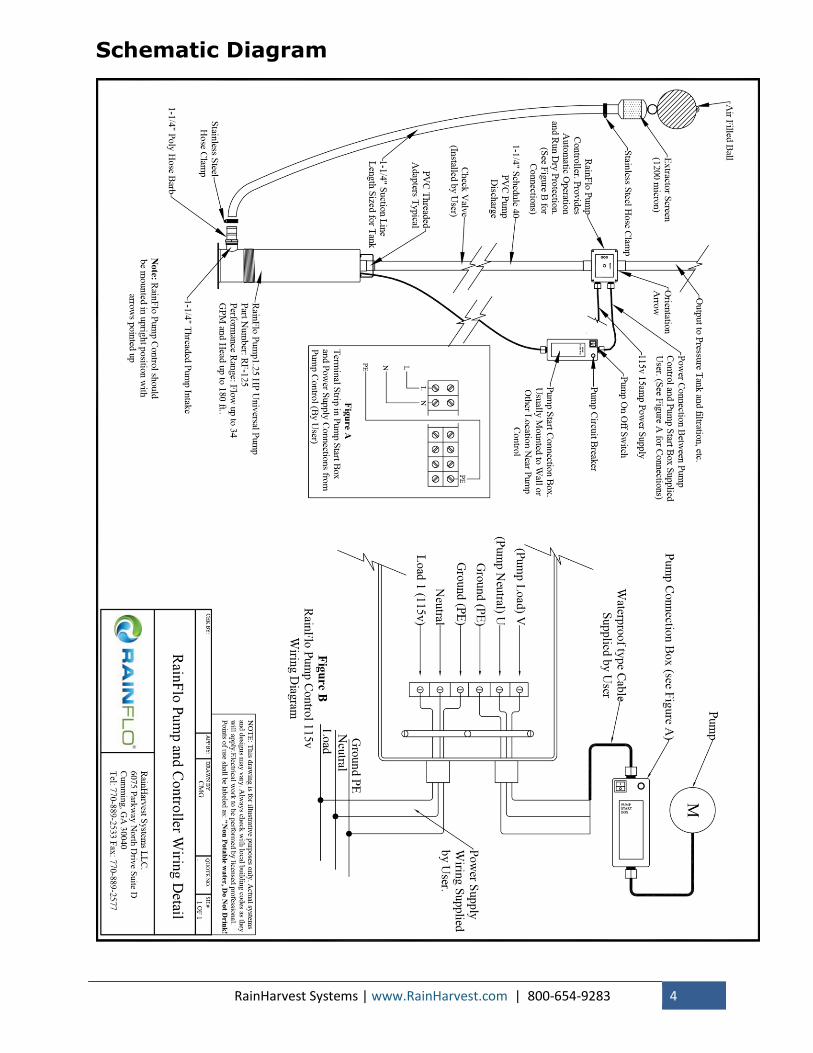
RainFlo Pump1.25 HP Universal PumpPart Number: RF-125.Performance Range: Flow up to 34GPM and Head up to 180 ft..
1-1/4" Schedule 40PVC PumpDischarge
1-1/4" Suction LineLength Sized for Tank
PUMPSTART BOX
RainFlo
Stainless SteelHose Clamp
1-1/4" Poly Hose Barb
1-1/4" Threaded Pump Intake
Pump Start Connection Box.Usually Mounted to Wall orOther Location Near Pump
Control
RainFlo PumpController.
(See Figure B forConnections)
PVC ThreadedAdapters (Typical)
Output to Irrigation, etc.
Pump On Off Switch
Air Filled Ball
Pump Circuit Breaker
115v 15amp Power Supply (Use Water ProofType Cable)
Extractor Screen(1200 micron)
Stainless Steel Hose Clamp
L N
PE
L
N
PE
Figure ATerminal Strip in Pump Start Boxand Power Supply Connections fromPump Control (By User)
Power Connection Between PumpControl and Pump Start Box Supplied byUser. (See Figure A for Connections)
Check Valve(Installed by User)
Note: RainFlo Pump Control should bemounted in upright position with arrowpointed up
FlowArrow
PVC Union
NOTE: This drawing is for illustrative purposes only. Actual systemsand designs may vary. Always check with local building codes as theywill apply.Electrical work to be performed by licensed professional.Points of use shall be labeled as: "Non Potable water, Do Not Drink!
. 1 OF 1CHK BY: APP BY: DRAWN BY QUOTE NO. SH.#
CMG
RainHarvest Systems LLC.6075 Parkway North Drive Suite DCumming, GA 30040Tel: 770-889-2533 Fax: 770-889-2577
RainFlo 1700IG GRAF Rainwater CollectionSystem

STORAGE TANK
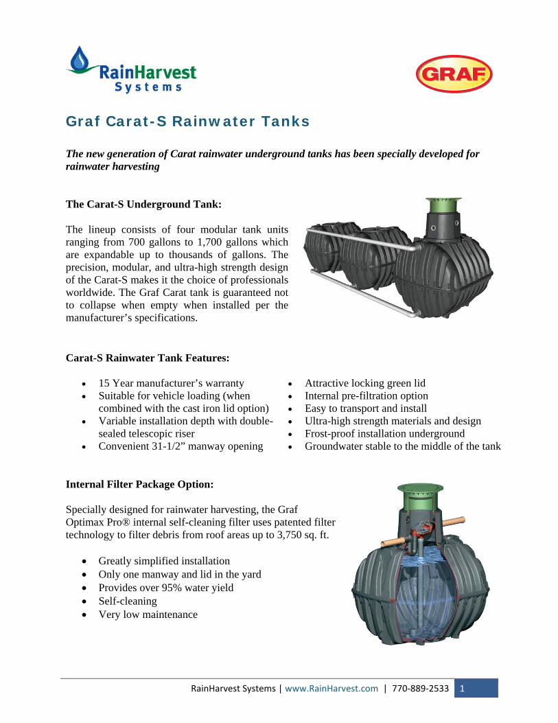
Graf Carat-S Rainwater Tanks The new generation of Carat rainwater underground tanks has been specially developed for rainwater harvesting The Carat-S Underground Tank:
The lineup consists of four modular tank units ranging from 700 gallons to 1,700 gallons which are expandable up to thousands of gallons. The precision, modular, and ultra-high strength design of the Carat-S makes it the choice of professionals worldwide. The Graf Carat tank is guaranteed not to collapse when empty when installed per the manufacturer’s specifications.
Carat-S Rainwater Tank Features:
• 15 Year manufacturer’s warranty • Suitable for vehicle loading (when
combined with the cast iron lid option) • Variable installation depth with double-
sealed telescopic riser • Convenient 31-1/2” manway opening
• Attractive locking green lid • Internal pre-filtration option • Easy to transport and install • Ultra-high strength materials and design • Frost-proof installation underground • Groundwater stable to the middle of the tank
Internal Filter Package Option:
Specially designed for rainwater harvesting, the Graf Optimax Pro® internal self-cleaning filter uses patented filter technology to filter debris from roof areas up to 3,750 sq. ft.
• Greatly simplified installation • Only one manway and lid in the yard • Provides over 95% water yield • Self-cleaning • Very low maintenance
RainHarvest Systems | www.RainHarvest.com | 770‐889‐2533 1
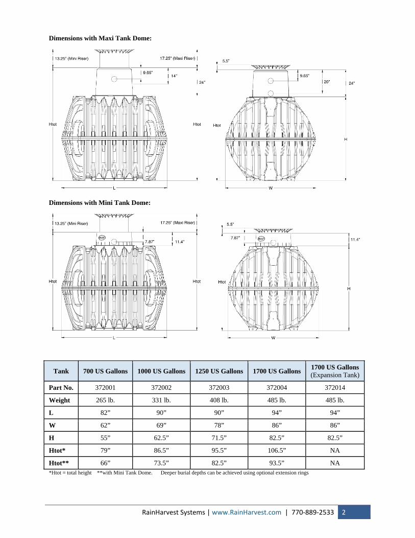
Dimensions with Maxi Tank Dome:
RainHarvest Systems | www.RainHarvest.com | 770‐889‐2533 2
Dimensions with Mini Tank Dome:
Tank 700 US Gallons 1000 US Gallons 1250 US Gallons 1700 US Gallons 1700 US Gallons(Expansion Tank)
Part No. 372001 372002 372003 372004 372014
Weight 265 lb. 331 lb. 408 lb. 485 lb. 485 lb.
L 82” 90” 90” 94” 94”
W 62” 69” 78” 86” 86”
H 55” 62.5” 71.5” 82.5” 82.5”
Htot* 79” 86.5” 95.5” 106.5” NA
Htot** 66” 73.5” 82.5” 93.5” *Htot = total height **with Mini Tank Dome. Deeper burial depths can be achieved using optional extension rings
NA
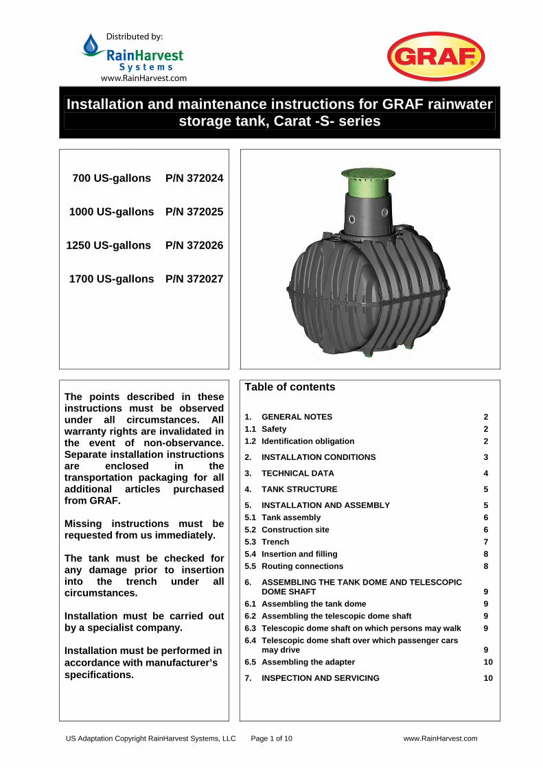
Installation and maintenance instructions for GRAF rainwater storage tank, Carat -S- series
700 US-gallons P/N 372024
1000 US-gallons P/N 372025
1250 US-gallons P/N 372026
1700 US-gallons P/N 372027
The points described in these instructions must be observed under all circumstances. All warranty rights are invalidated in the event of non-observance. Separate installation instructions are enclosed in the transportation packaging for all additional articles purchased from GRAF. Missing instructions must be requested from us immediately. The tank must be checked for any damage prior to insertion into the trench under all circumstances. Installation must be carried out by a specialist company. Installation must be performed inaccordance with manufacturer’sspecifications.
Table of contents 1. GENERAL NOTES 2 1.1 Safety 2 1.2 2 noitagilbo noitacifitnedI
3 SNOITIDNOC NOITALLATSNI .2
3. TECHNICAL DATA 4
4. TANK STRUCTURE 5
5 YLBMESSA DNA NOITALLATSNI .55.1 Tank assembly 6 5.2 Construction site 6 5.3 Trench 7 5.4 Insertion and filling 8 5.5 Routing connections 8
6. ASSEMBLING THE TANK DOME AND TELESCOPIC DOME SHAFT 9
6.1 9 emod knat eht gnilbmessA 6.2 Assembling the telescopic dome shaft 9 6.3 Telescopic dome shaft on which persons may walk 9 6.4 Telescopic dome shaft over which passenger cars
may drive 9 6.5 01 retpada eht gnilbmessA
01 GNICIVRES DNA NOITCEPSNI .7
Distributed by:
www.RainHarvest.com
US Adaptation Copyright RainHarvest Systems, LLC Page 1 of 10 www.RainHarvest.com
[email protected] www.graf.info
1. General notes
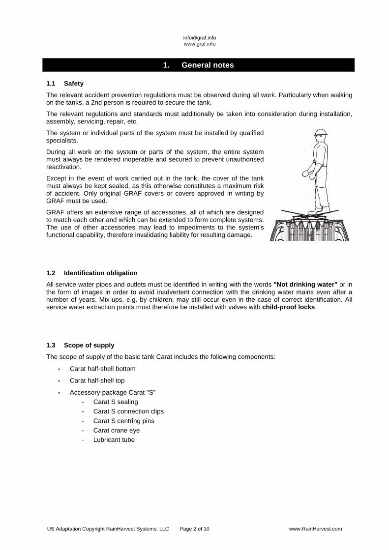
1.1 Safety
The relevant accident prevention regulations must be observed during all work. Particularly when walking on the tanks, a 2nd person is required to secure the tank.
The relevant regulations and standards must additionally be taken into consideration during installation, assembly, servicing, repair, etc.
The system or individual parts of the system must be installed by qualified specialists.
During all work on the system or parts of the system, the entire system must always be rendered inoperable and secured to prevent unauthorised reactivation.
Except in the event of work carried out in the tank, the cover of the tank must always be kept sealed, as this otherwise constitutes a maximum risk of accident. Only original GRAF covers or covers approved in writing by GRAF must be used.
GRAF offers an extensive range of accessories, all of which are designed to match each other and which can be extended to form complete systems. The use of other accessories may lead to impediments to the system's functional capability, therefore invalidating liability for resulting damage.
1.2 Identification obligation
All service water pipes and outlets must be identified in writing with the words "Not drinking water" or in the form of images in order to avoid inadvertent connection with the drinking water mains even after a number of years. Mix-ups, e.g. by children, may still occur even in the case of correct identification. All service water extraction points must therefore be installed with valves with child-proof locks.
1.3 Scope of supply
The scope of supply of the basic tank Carat includes the following components:
• Carat half-shell bottom
• Carat half-shell top
• Accessory-package Carat "S" - Carat S sealing - Carat S connection clips - Carat S centring pins - Carat crane eye - Lubricant tube
US Adaptation Copyright RainHarvest Systems, LLC Page 2 of 10 www.RainHarvest.com
[email protected] www.graf.info
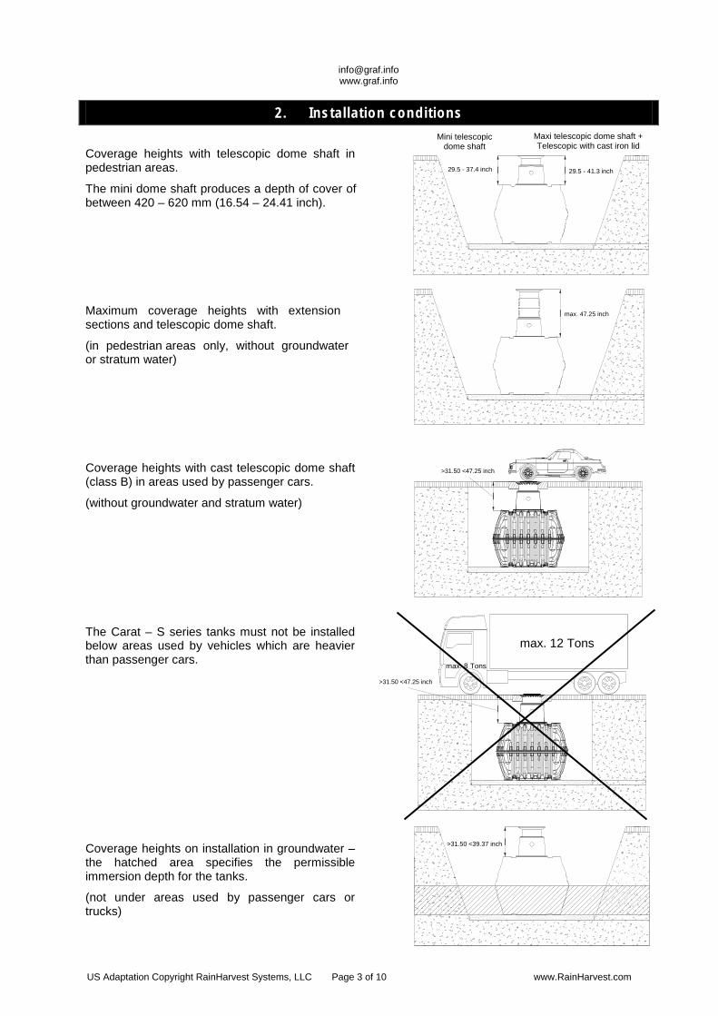
2. Installation conditions
Coverage heights with telescopic dome shaft in pedestrian areas.
The mini dome shaft produces a depth of cover of between 420 – 620 mm (16.54 – 24.41 inch).
||29.5 - 37.4 inch 29.5 - 41.3 inch
Maximum coverage heights with extensionsections and telescopic dome shaft.
(in pedestrian areas only, without groundwater or stratum water)
| max. 47.25 inch
Coverage heights with cast telescopic dome shaft (class B) in areas used by passenger cars.
(without groundwater and stratum water) |
>31.50 <47.25 inch
The Carat – S series tanks must not be installed below areas used by vehicles which are heavier than passenger cars.
|
max. 12 Tons
max. 8 Tons
>31.50 <47.25 inch
Coverage heights on installation in groundwater – the hatched area specifies the permissible immersion depth for the tanks.
(not under areas used by passenger cars or trucks)
|>31.50 <39.37 inch
Maxi telescopic dome shaft + Telescopic with cast iron lid
Mini telescopic dome shaft
US Adaptation Copyright RainHarvest Systems, LLC Page 3 of 10 www.RainHarvest.com
[email protected] www.graf.info
Htot
|
|
L
|
|
Htot
||
|
W
H
Htot
|
Htot
|
Htot
||
H
|
Htot
|
L
|
W
290 mm11.42 inch
245 mm9.65 inch
245 mm9.65 inch
245 mm9.65 inch 610 mm
24.02 inch610 mm24.02 inch
355 mm13.98 inch 520 mm
20.47 inch
|
|
|340 mm (Mini)
13.38 inch (Mini)440 mm (Maxi)
17.32 inch (Maxi)
140 mm5.51 inch
290 mm11.42 inch
200 mm7.87 inch
200 mm7.87 inch
200 mm7.87 inch
340 mm (Mini)13.38 inch (Mini)
440 mm (Maxi)17.32 inch (Maxi)
140 mm5.51 inch
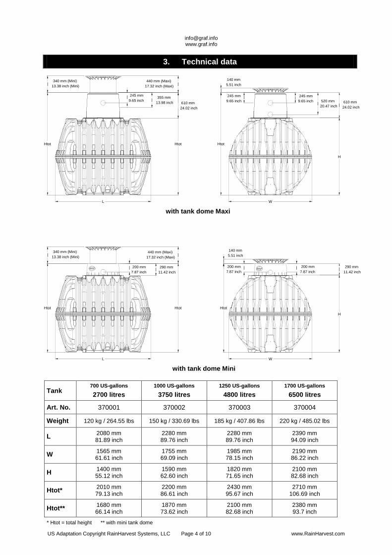
3. Technical data
Tank 700 US-gallons 2700 litres
1000 US-gallons 3750 litres
1250 US-gallons 4800 litres
1700 US-gallons 6500 litres
Art. No. 370001 370002 370003 370004
Weight 120 kg / 264.55 lbs 150 kg / 330.69 lbs 185 kg / 407.86 lbs 220 kg / 485.02 lbs
L 2080 mm 81.89 inch
2280 mm 89.76 inch
2280 mm 89.76 inch
2390 mm 94.09 inch
W 1565 mm 61.61 inch
1755 mm 69.09 inch
1985 mm 78.15 inch
2190 mm 86.22 inch
H 1400 mm 55.12 inch
1590 mm 62.60 inch
1820 mm 71.65 inch
2100 mm 82.68 inch
Htot* 2010 mm 79.13 inch
2200 mm 86.61 inch
2430 mm 95.67 inch
2710 mm 106.69 inch
Htot** 1680 mm 66.14 inch
1870 mm 73.62 inch
2100 mm 82.68 inch
2380 mm 93.7 inch
* Htot = total height ** with mini tank dome
with tank dome Mini
with tank dome Maxi
US Adaptation Copyright RainHarvest Systems, LLC Page 4 of 10 www.RainHarvest.com
[email protected] www.graf.info
5
3
4
5
2
2
3
6
6
4
1
1
5
2
3
6
7
4
1
ß
ß according to DIN 4124
6 3
1 4 2 57
≥ 4 inch
≥ 6 inch
≤ 12 inch
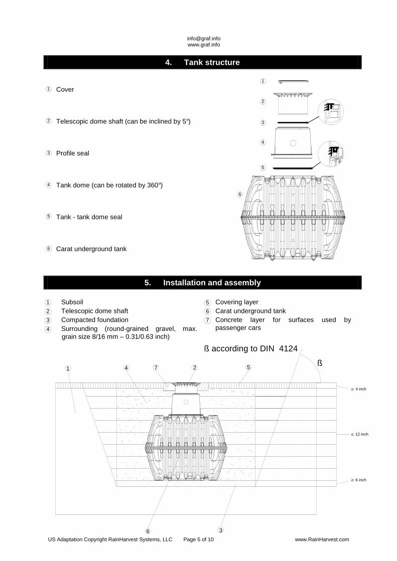
4. Tank structure
Cover
Telescopic dome shaft (can be inclined by 5° )
Profile seal
Tank dome (can be rotated by 360° )
Tank - tank dome seal
Carat underground tank
5. Installation and assembly
Subsoil Telescopic dome shaft Compacted foundation Surrounding (round-grained gravel, max.
grain size 8/16 mm – 0.31/0.63 inch)
Covering layer Carat underground tank Concrete layer for surfaces used by
passenger cars
US Adaptation Copyright RainHarvest Systems, LLC Page 5 of 10 www.RainHarvest.com
[email protected] www.graf.info
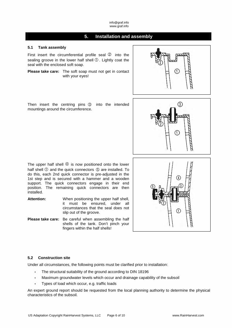
5. Installation and assembly
5.1 Tank assembly
First insert the circumferential profile seal into the sealing groove in the lower half shell . Lightly coat the seal with the enclosed soft soap.
Please take care: The soft soap must not get in contact with your eyes!
Then insert the centring pins into the intended mountings around the circumference.
The upper half shell is now positioned onto the lower half shell and the quick connectors are installed. To do this, each 2nd quick connector is pre-adjusted in the 1st step and is secured with a hammer and a wooden support. The quick connectors engage in their end position. The remaining quick connectors are then installed.
Attention: When positioning the upper half shell, it must be ensured, under all circumstances that the seal does not slip out of the groove.
Please take care: Be careful when assembling the half shells of the tank. Don’t pinch your fingers within the half shells!
5.2 Construction site
Under all circumstances, the following points must be clarified prior to installation:
• The structural suitability of the ground according to DIN 18196 • Maximum groundwater levels which occur and drainage capability of the subsoil • Types of load which occur, e.g. traffic loads
An expert ground report should be requested from the local planning authority to determine the physical characteristics of the subsoil.
US Adaptation Copyright RainHarvest Systems, LLC Page 6 of 10 www.RainHarvest.com
[email protected] www.graf.info
|>800 <1000 mm
>31.50 <39.37 inch
5. Installation and assembly
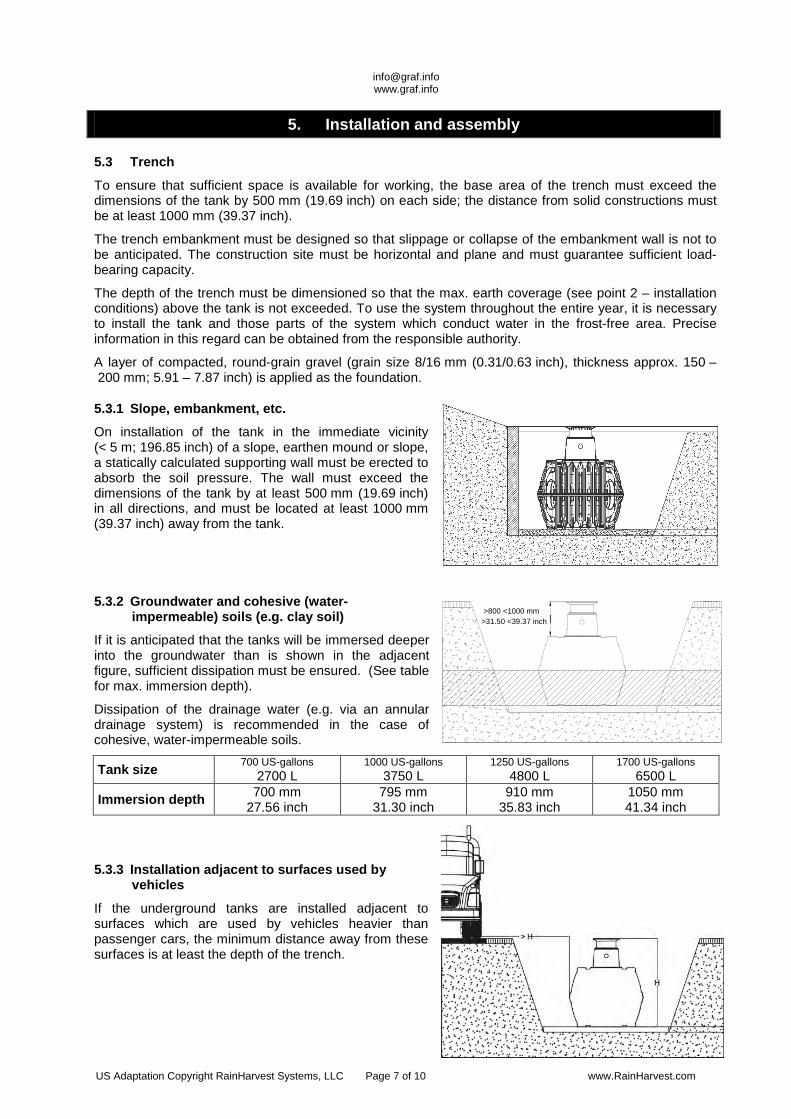
5.3 Trench
To ensure that sufficient space is available for working, the base area of the trench must exceed the dimensions of the tank by 500 mm (19.69 inch) on each side; the distance from solid constructions must be at least 1000 mm (39.37 inch).
The trench embankment must be designed so that slippage or collapse of the embankment wall is not to be anticipated. The construction site must be horizontal and plane and must guarantee sufficient load-bearing capacity.
The depth of the trench must be dimensioned so that the max. earth coverage (see point 2 – installation conditions) above the tank is not exceeded. To use the system throughout the entire year, it is necessary to install the tank and those parts of the system which conduct water in the frost-free area. Precise information in this regard can be obtained from the responsible authority.
A layer of compacted, round-grain gravel (grain size 8/16 mm (0.31/0.63 inch), thickness approx. 150 – 200 mm; 5.91 – 7.87 inch) is applied as the foundation.
5.3.1 Slope, embankment, etc.
On installation of the tank in the immediate vicinity (< 5 m; 196.85 inch) of a slope, earthen mound or slope, a statically calculated supporting wall must be erected to absorb the soil pressure. The wall must exceed the dimensions of the tank by at least 500 mm (19.69 inch) in all directions, and must be located at least 1000 mm (39.37 inch) away from the tank.
5.3.2 Groundwater and cohesive (water-impermeable) soils (e.g. clay soil)
If it is anticipated that the tanks will be immersed deeper into the groundwater than is shown in the adjacent figure, sufficient dissipation must be ensured. (See table for max. immersion depth).
Dissipation of the drainage water (e.g. via an annular drainage system) is recommended in the case of cohesive, water-impermeable soils.
Tank size 700 US-gallons 2700 L
1000 US-gallons 3750 L
1250 US-gallons 4800 L
1700 US-gallons 6500 L
Immersion depth 700 mm 27.56 inch
795 mm 31.30 inch
910 mm 35.83 inch
1050 mm 41.34 inch
5.3.3 Installation adjacent to surfaces used by vehicles
If the underground tanks are installed adjacent to surfaces which are used by vehicles heavier than passenger cars, the minimum distance away from these surfaces is at least the depth of the trench.
US Adaptation Copyright RainHarvest Systems, LLC Page 7 of 10 www.RainHarvest.com
[email protected] www.graf.info
-
>600 mm>23.62 inch
-
1/31.
2. 3/3
500 mm 19.69 inch
- >1000 mm
>39.37 inch
Sewer
>1%
>1%>1%
5. Installation and assembly
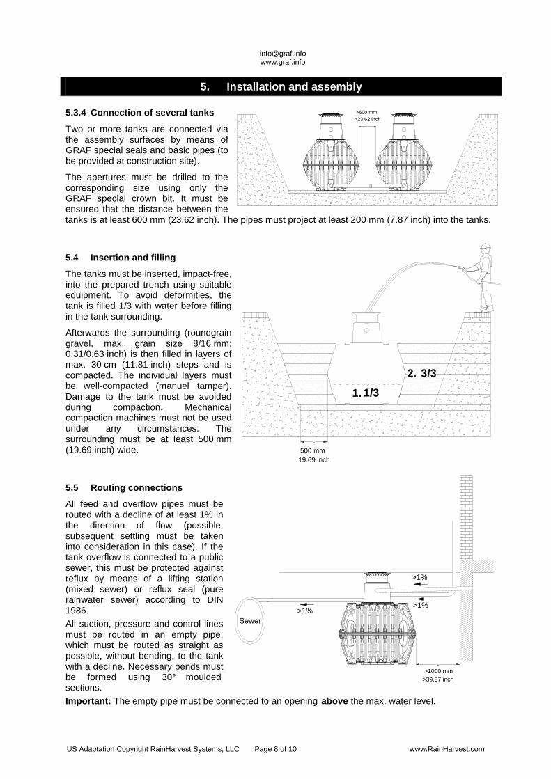
5.3.4 Connection of several tanks
Two or more tanks are connected via the assembly surfaces by means of GRAF special seals and basic pipes (to be provided at construction site).
The apertures must be drilled to the corresponding size using only the GRAF special crown bit. It must be ensured that the distance between the tanks is at least 600 mm (23.62 inch). The pipes must project at least 200 mm (7.87 inch) into the tanks.
5.4 Insertion and filling
The tanks must be inserted, impact-free, into the prepared trench using suitable equipment. To avoid deformities, the tank is filled 1/3 with water before filling in the tank surrounding.
Afterwards the surrounding (roundgrain gravel, max. grain size 8/16 mm; 0.31/0.63 inch) is then filled in layers of max. 30 cm (11.81 inch) steps and is compacted. The individual layers must be well-compacted (manuel tamper). Damage to the tank must be avoided during compaction. Mechanical compaction machines must not be used under any circumstances. The surrounding must be at least 500 mm (19.69 inch) wide.
5.5 Routing connections
All feed and overflow pipes must be routed with a decline of at least 1% in the direction of flow (possible, subsequent settling must be taken into consideration in this case). If the tank overflow is connected to a public sewer, this must be protected against reflux by means of a lifting station (mixed sewer) or reflux seal (pure rainwater sewer) according to DIN 1986. All suction, pressure and control lines must be routed in an empty pipe, which must be routed as straight as possible, without bending, to the tank with a decline. Necessary bends must be formed using 30° moulded sections. Important: The empty pipe must be connected to an opening above the max. water level.
US Adaptation Copyright RainHarvest Systems, LLC Page 8 of 10 www.RainHarvest.com
[email protected] www.graf.info
6. Assembling the tank dome and telescopic dome shaft
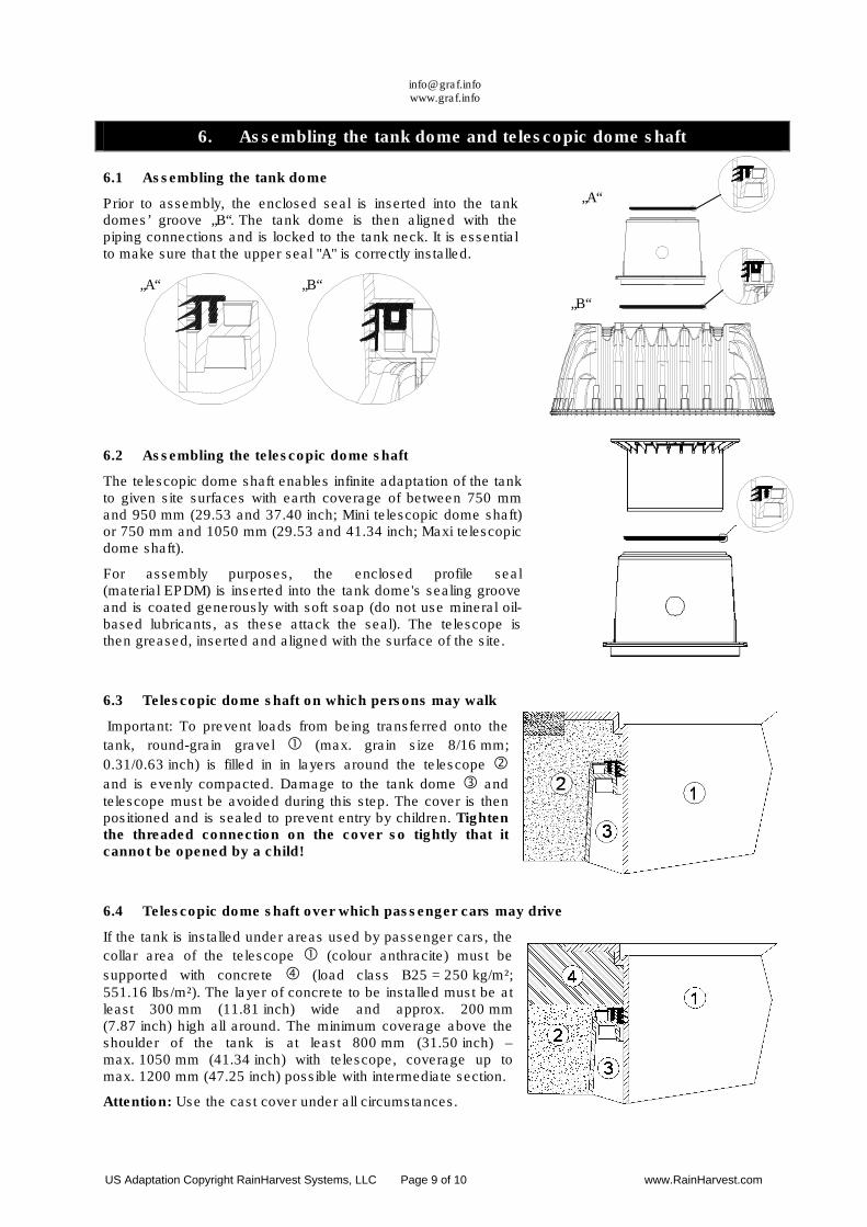
6.1 Assembling the tank dome
Prior to assembly, the enclosed seal is inserted into the tank domes’ groove „B“. The tank dome is then aligned with the piping connections and is locked to the tank neck. It is essential to make sure that the upper seal "A" is correctly installed.
6.2 Assembling the telescopic dome shaft
The telescopic dome shaft enables infinite adaptation of the tank to given site surfaces with earth coverage of between 750 mm and 950 mm (29.53 and 37.40 inch; Mini telescopic dome shaft) or 750 mm and 1050 mm (29.53 and 41.34 inch; Maxi telescopic dome shaft).
For assembly purposes, the enclosed profile seal (material EPDM) is inserted into the tank dome's sealing groove and is coated generously with soft soap (do not use mineral oil-based lubricants, as these attack the seal). The telescope is then greased, inserted and aligned with the surface of the site.
6.3 Telescopic dome shaft on which persons may walk
Important: To prevent loads from being transferred onto the
tank, round-grain gravel � (max. grain size 8/16 mm;
0.31/0.63 inch) is filled in in layers around the telescope �
and is evenly compacted. Damage to the tank dome � and telescope must be avoided during this step. The cover is then positioned and is sealed to prevent entry by children. Tighten the threaded connection on the cover so tightly that it cannot be opened by a child!
6.4 Telescopic dome shaft over which passenger cars may drive
If the tank is installed under areas used by passenger cars, the
collar area of the telescope � (colour anthracite) must be
supported with concrete � (load class B25 = 250 kg/m²; 551.16 lbs/m²). The layer of concrete to be installed must be at least 300 mm (11.81 inch) wide and approx. 200 mm (7.87 inch) high all around. The minimum coverage above the shoulder of the tank is at least 800 mm (31.50 inch) – max. 1050 mm (41.34 inch) with telescope, coverage up to max. 1200 mm (47.25 inch) possible with intermediate section.
Attention: Use the cast cover under all circumstances.
„B“
„A“
„A“ „B“
US Adaptation Copyright RainHarvest Systems, LLC Page 9 of 10 www.RainHarvest.com
[email protected] www.graf.info
6. Assembling the tank dome and telescopic dome shaft
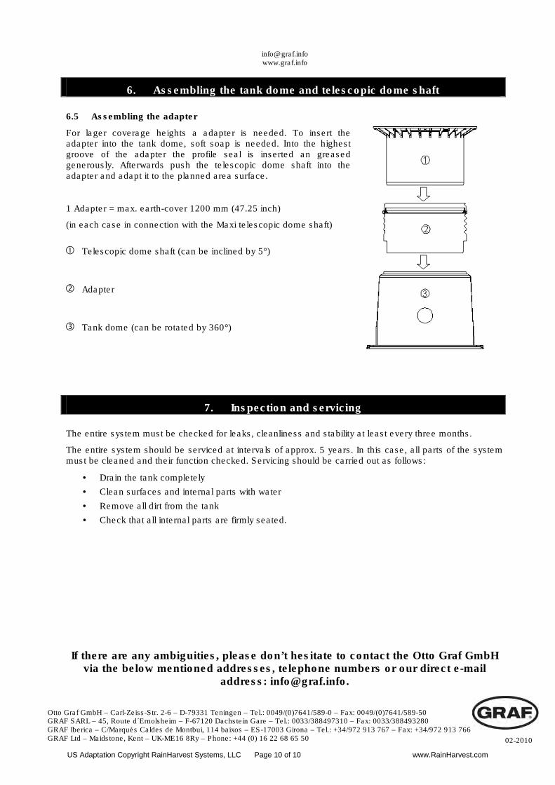
6.5 Assembling the adapter
For lager coverage heights a adapter is needed. To insert the adapter into the tank dome, soft soap is needed. Into the highest groove of the adapter the profile seal is inserted an greased generously. Afterwards push the telescopic dome shaft into the adapter and adapt it to the planned area surface.
1 Adapter = max. earth-cover 1200 mm (47.25 inch)
(in each case in connection with the Maxi telescopic dome shaft)
7. Inspection and servicing
The entire system must be checked for leaks, cleanliness and stability at least every three months.
The entire system should be serviced at intervals of approx. 5 years. In this case, all parts of the system must be cleaned and their function checked. Servicing should be carried out as follows:
• Drain the tank completely
• Clean surfaces and internal parts with water
• Remove all dirt from the tank
• Check that all internal parts are firmly seated.
If there are any ambiguities, please don’t hesitate to contact the Otto Graf GmbH via the below mentioned addresses, telephone numbers or our direct e-mail
address: [email protected].
� Telescopic dome shaft (can be inclined by 5°)
� Adapter
� Tank dome (can be rotated by 360°)
Otto Graf GmbH – Carl-Zeiss-Str. 2-6 – D-79331 Teningen – Tel.: 0049/(0)7641/589-0 – Fax: 0049/(0)7641/589-50 GRAF SARL – 45, Route d´Ernolsheim – F-67120 Dachstein Gare – Tel.: 0033/388497310 – Fax: 0033/388493280 GRAF Iberica – C/Marquès Caldes de Montbui, 114 baixos – ES-17003 Girona – Tel.: +34/972 913 767 – Fax: +34/972 913 766 GRAF Ltd – Maidstone, Kent – UK-ME16 8Ry – Phone: +44 (0) 16 22 68 65 50 02-2010
US Adaptation Copyright RainHarvest Systems, LLC Page 10 of 10 www.RainHarvest.com
RAINWATER
PRE-FILTER
Optimax® Pro Internal Filter340037
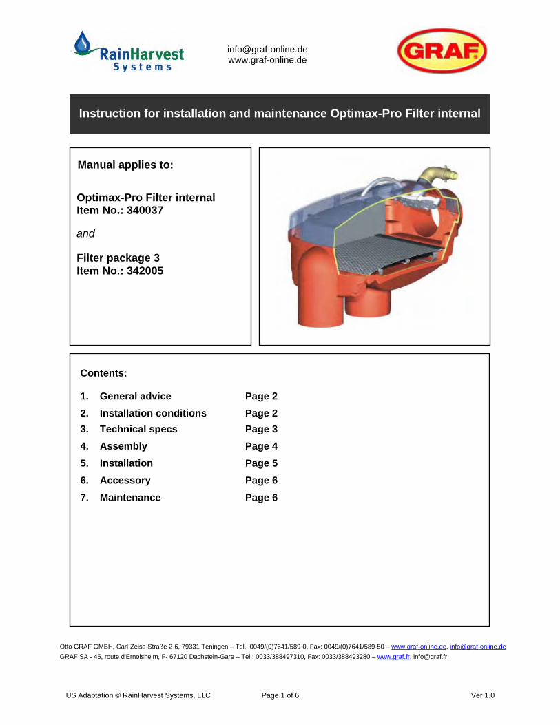
Optimax-Pro Filter internal Item No.: 340037
Filter package 3 Item No.: 342005
Instruction for installation and maintenance Optimax-Pro Filter internal
Contents:
1. General advice Page 22. Installation conditions Page 2 3. Technical specs Page 3 4. Assembly Page 4 5. Installation Page 5 6. Accessory Page 6 7. Maintenance Page 6
Otto GRAF GMBH, Carl-Zeiss-Straße 2-6, 79331 Teningen – Tel.: 0049/(0)7641/589-0, Fax: 0049/(0)7641/589-50 – www.graf-online.de, [email protected] SA - 45, route d'Ernolsheim, F- 67120 Dachstein-Gare – Tel.: 0033/388497310, Fax: 0033/388493280 – www.graf.fr, [email protected]
and
Manual applies to:
US Adaptation © RainHarvest Systems, LLC Page 1 of 6 Ver 1.0
Please read and follow all instructions provided by this manual. In case of non-compliance, any warranty claim is void. For every accessory supplied by GRAF you will receive separate installation instructions which will be enclosed in the transport packaging.
Any missing instructions have to be requested immediately.
Previous to installation and mounting, it is necessary to test all components fo rpossible damages.
1. General advice
1.1 Safety For all work performed, please observe the relevant domestic rules for accident prevention.
Furthermore all relevant rules and norms should be observed during installation, assembly, maintenance and repairing. Please find relating advice in the respective chapters of this instruction manual.
The installation of this rainwater harvesting system and its different components should beperformed in a professional manner and according to the enclosed instruction manual.
For all workings on the system and its components respectively the whole system has to bestopped and protected against unauthorized resetting.GRAF offers a wide range of accessories which are all matched to each other and which can be extended to complete systems. The use of other accessories may lead to dysfunctions and the suspension of the liability for resulting damages.
1.2 Marking responsibility
The processed water is not suitable for consumption and for body hygiene. All plumbing and tappings of process water must be marked with non-potable water stickers, writing or by illustrations according to the relevant domestic rules, in order to avoid the wrong connection with the drinking water pipework even after years of use. Improper use may even arise with correct marking, e.g. by children. Therefore all process water tappings should be installed with child-safe valves.
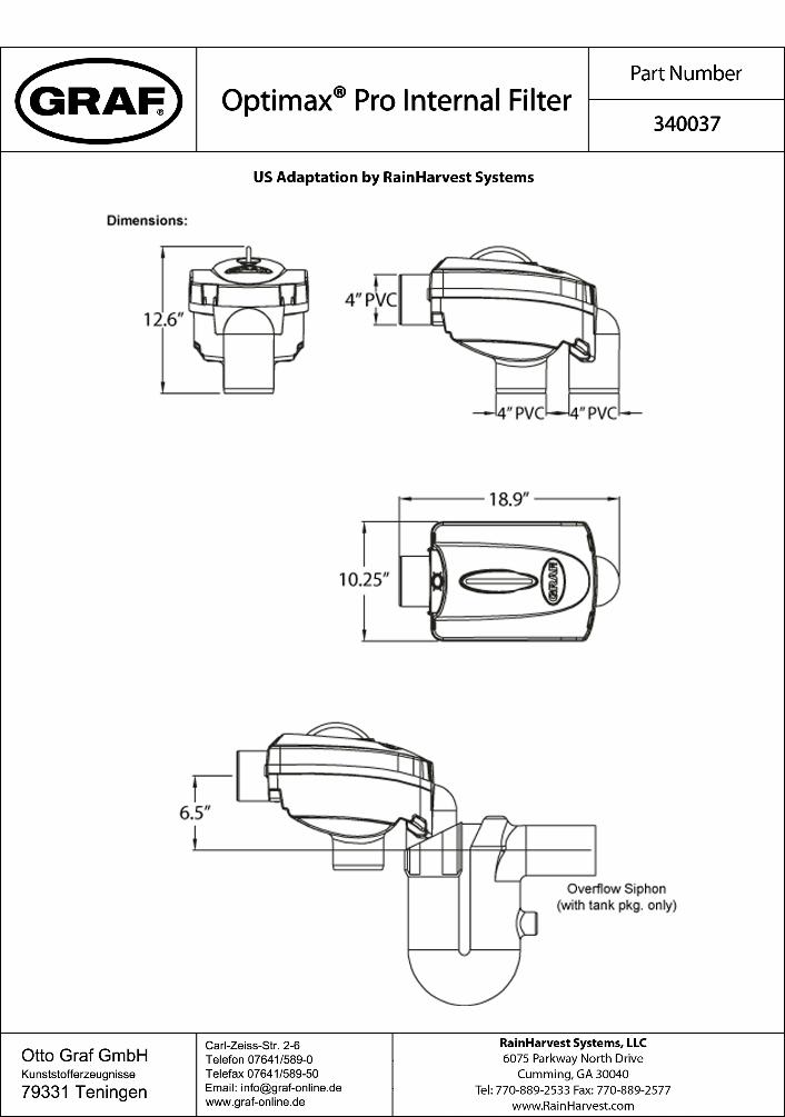
2.1 Optimax-Pro Filter internal - The Optimax-Pro Filter is suitable for installation in a manhole or underground tank. - The difference between inflow and outflow is 6.5”. - The filter is suitable for roof areas up to 3,750 ft². - The mesh width of the sieve insert is 0.35 mm.
2. Installation conditiions
US Adaptation © RainHarvest Systems, LLC Page 2 of 6 Ver 1.0
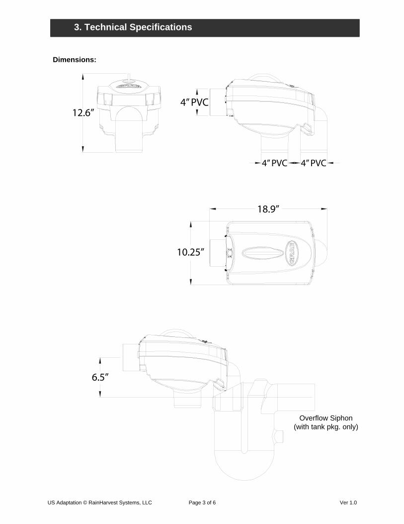
Dimensions:
3. TECHNISCHE DATEN 3. Technical Specifications
12.6”4” PVC
4” PVC4” PVC
18.9”
10.25”
6.5”
Overflow Siphon(with tank pkg. only)
US Adaptation © RainHarvest Systems, LLC Page 3 of 6 Ver 1.0
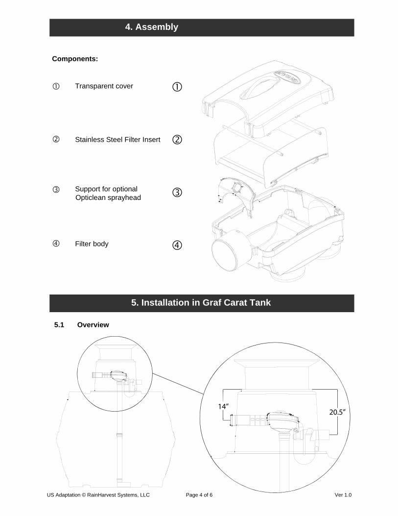
Transparent cover
Stainless Steel Filter Insert
Support for optional Opticlean sprayhead
Filter body
5. Installation in Graf Carat Tank
4. Assembly
5.1 Overview
14”
Components:
20.5”
US Adaptation © RainHarvest Systems, LLC Page 4 of 6 Ver 1.0
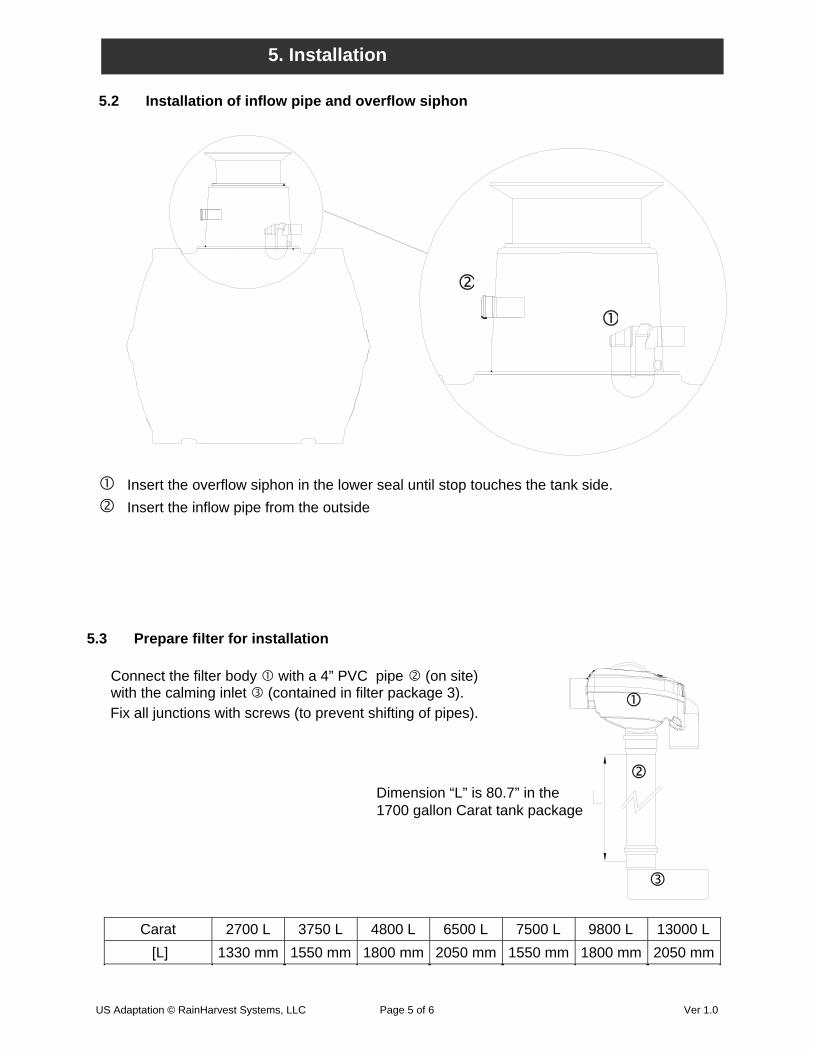
5. Installation
Insert the overflow siphon in the lower seal until stop touches the tank side.Insert the inflow pipe from the outside
5.3 Prepare filter for installation
Connect the filter body with a 4” PVC pipe (on site) with the calming inlet (contained in filter package 3).
5.2 Installation of inflow pipe and overflow siphon
Carat 2700 L 3750 L 4800 L 6500 L 7500 L 9800 L 13000 L [L] 1330 mm 1550 mm 1800 mm 2050 mm 1550 mm 1800 mm 2050 mm
Fix all junctions with screws (to prevent shifting of pipes).
Dimension “L” is 80.7” in the1700 gallon Carat tank package
US Adaptation © RainHarvest Systems, LLC Page 5 of 6 Ver 1.0
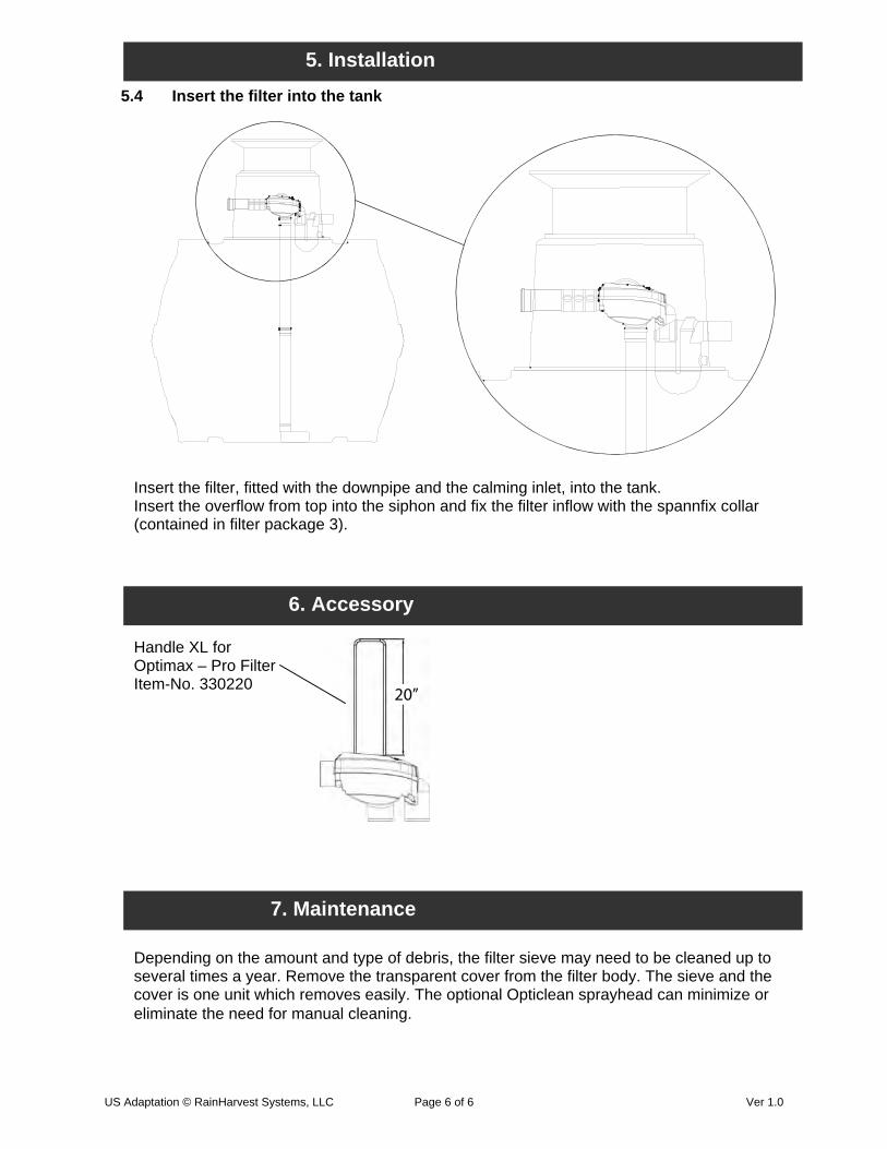
5.4 Insert the filter into the tank
Insert the filter, fitted with the downpipe and the calming inlet, into the tank. Insert the overflow from top into the siphon and fix the filter inflow with the spannfix collar (contained in filter package 3).
5. Installation
Depending on the amount and type of debris, the filter sieve may need to be cleaned up to several times a year. Remove the transparent cover from the filter body. The sieve and thecover is one unit which removes easily. The optional Opticlean sprayhead can minimize oreliminate the need for manual cleaning.
6. Accessory
Handle XL for Optimax – Pro FilterItem-No. 330220
7. Maintenance
20”
US Adaptation © RainHarvest Systems, LLC Page 6 of 6 Ver 1.0

PUMPING
SYSTEM
RainHarvest Systems | www.RainHarvest.com | 800-654-9283 1
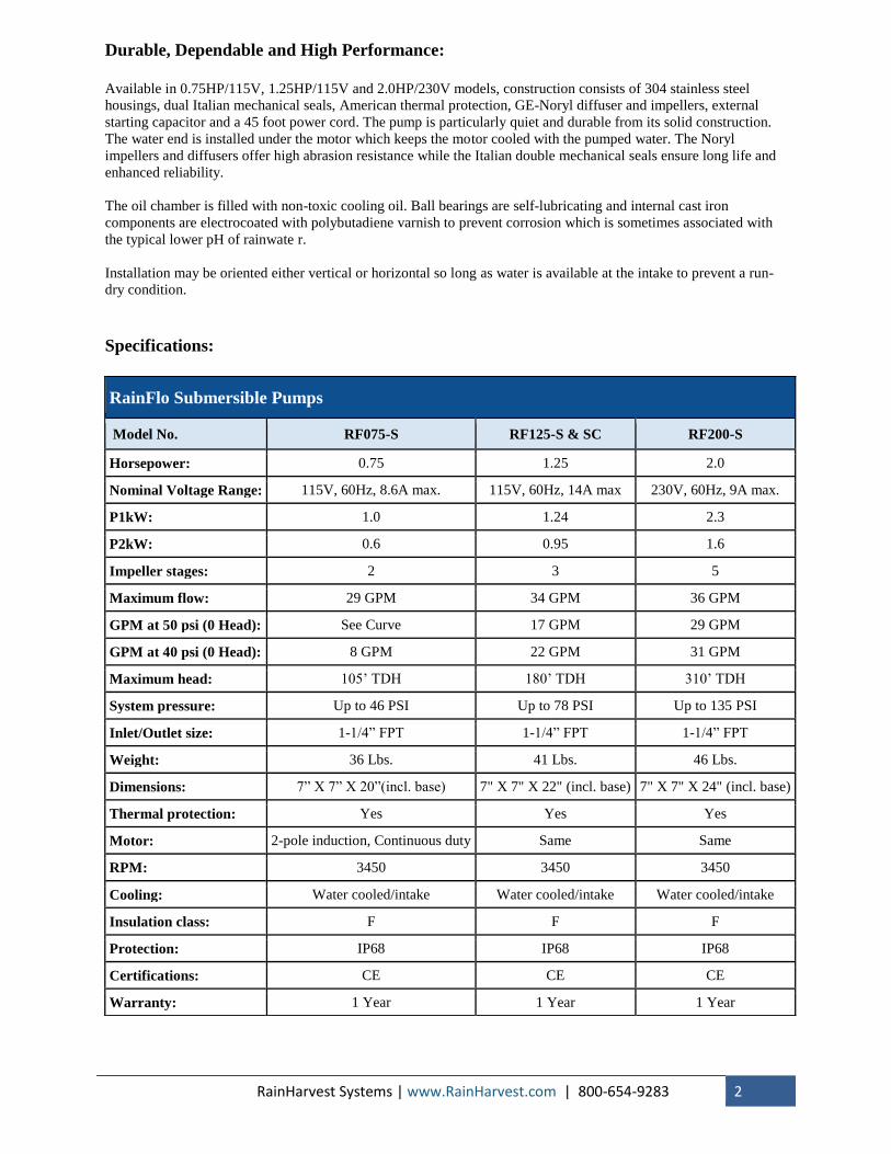
Universal Rainwater Pumps
High performance multi-stage rainwater pumps for residential, commercial, and light-
industrial rainwater collection systems.
Submersible and External Mounted Capability:
RainFlo universal pumps are specially designed
for the unique requirements of rainwater collection
systems. Equipped with a large threaded bottom
inlet large for internal flow-based cooling and
connection to a floating filter, these pumps can be
installed vertically or horizontally and they can
either be submersed inside a tank or mounted
externally on the ground or other platform. Other
features include a stainless steel base, adjustable
float switch for run-dry protection, external
capacitor housed in a wiring box with circuit
breaker and master on/off switch for long life and
ease of maintenance.
Pump Performance:
RainHarvest Systems | www.RainHarvest.com | 800-654-9283 2
Durable, Dependable and High Performance:
Available in 0.75HP/115V, 1.25HP/115V and 2.0HP/230V models, construction consists of 304 stainless steel
housings, dual Italian mechanical seals, American thermal protection, GE-Noryl diffuser and impellers, external
starting capacitor and a 45 foot power cord. The pump is particularly quiet and durable from its solid construction.
The water end is installed under the motor which keeps the motor cooled with the pumped water. The Noryl
impellers and diffusers offer high abrasion resistance while the Italian double mechanical seals ensure long life and
enhanced reliability.
The oil chamber is filled with non-toxic cooling oil. Ball bearings are self-lubricating and internal cast iron
components are electrocoated with polybutadiene varnish to prevent corrosion which is sometimes associated with
the typical lower pH of rainwate r.
Installation may be oriented either vertical or horizontal so long as water is available at the intake to prevent a run-
dry condition.
Specifications:
RainFlo Submersible Pumps
Model No. RF075-S RF125-S & SC RF200-S
Horsepower: 0.75 1.25 2.0
Nominal Voltage Range: 115V, 60Hz, 8.6A max. 115V, 60Hz, 14A max 230V, 60Hz, 9A max.
P1kW: 1.0 1.24 2.3
P2kW: 0.6 0.95 1.6
Impeller stages: 2 3 5
Maximum flow: 29 GPM 34 GPM 36 GPM
GPM at 50 psi (0 Head): See Curve 17 GPM 29 GPM
GPM at 40 psi (0 Head): 8 GPM 22 GPM 31 GPM
Maximum head: 105’ TDH 180’ TDH 310’ TDH
System pressure: Up to 46 PSI Up to 78 PSI Up to 135 PSI
Inlet/Outlet size: 1-1/4” FPT 1-1/4” FPT 1-1/4” FPT
Weight: 36 Lbs. 41 Lbs. 46 Lbs.
Dimensions: 7” X 7” X 20”(incl. base) 7" X 7" X 22" (incl. base) 7" X 7" X 24" (incl. base)
Thermal protection: Yes Yes Yes
Motor: 2-pole induction, Continuous duty Same Same
RPM: 3450 3450 3450
Cooling: Water cooled/intake Water cooled/intake Water cooled/intake
Insulation class: F F F
Protection: IP68 IP68 IP68
Certifications: CE CE CE
Warranty: 1 Year 1 Year 1 Year
RainHarvest Systems | www.RainHarvest.com | 800-654-9283 3
Installation Instructions
Mounting location:
The pump may be mounted vertically or horizontally and may be fully or partially submersed or mounted externally
on the ground or other sturdy platform. When mounted externally, the pump must be safely and securely mounted in
manner which prevents exposure to electrical connections and in a location which prevents damage and exposure to
freezing temperatures.
Environmental considerations:
If the pump may be exposed to freezing temperatures, the pump must be fully drained and protected with a food-
grade antifreeze. The pump start box offers water resistance but should be mounted in a location away from direct
exposure to rain, humidity, snow, excessive heat and direct sunlight.
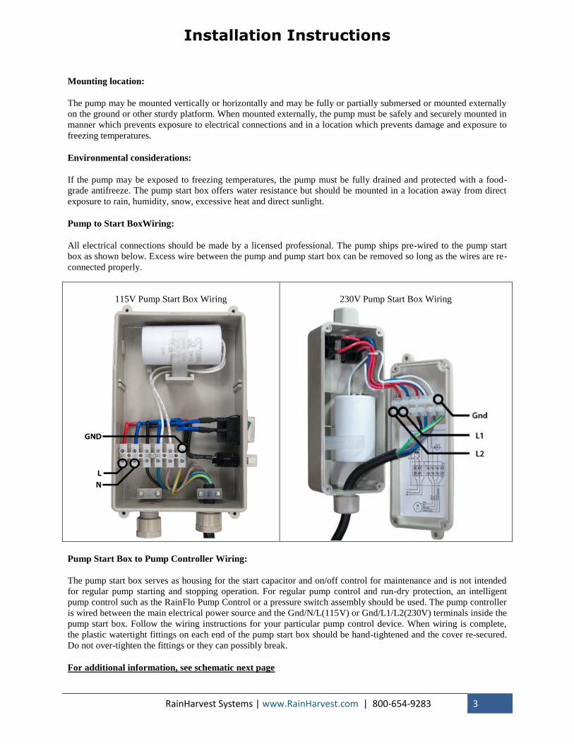
Pump to Start BoxWiring:
All electrical connections should be made by a licensed professional. The pump ships pre-wired to the pump start
box as shown below. Excess wire between the pump and pump start box can be removed so long as the wires are re-
connected properly.
115V Pump Start Box Wiring
230V Pump Start Box Wiring
Pump Start Box to Pump Controller Wiring:
The pump start box serves as housing for the start capacitor and on/off control for maintenance and is not intended
for regular pump starting and stopping operation. For regular pump control and run-dry protection, an intelligent
pump control such as the RainFlo Pump Control or a pressure switch assembly should be used. The pump controller
is wired between the main electrical power source and the Gnd/N/L(115V) or Gnd/L1/L2(230V) terminals inside the
pump start box. Follow the wiring instructions for your particular pump control device. When wiring is complete,
the plastic watertight fittings on each end of the pump start box should be hand-tightened and the cover re-secured.
Do not over-tighten the fittings or they can possibly break.
For additional information, see schematic next page
RainHarvest Systems | www.RainHarvest.com | 800-654-9283 4
Schematic Diagram

It is the installer’s responsibility to read, understand and comply with these instructions.
®
Installation instructions for the PC115A Pump Controller
page 2
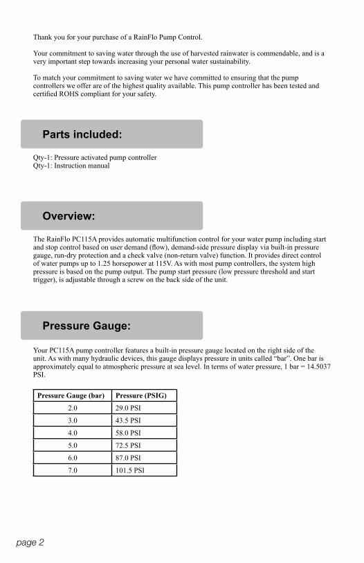
Thank you for your purchase of a RainFlo Pump Control.
Your commitment to saving water through the use of harvested rainwater is commendable, and is a very important step towards increasing your personal water sustainability.
To match your commitment to saving water we have committed to ensuring that the pump controllers we offer are of the highest quality available. This pump controller has been tested and certified ROHS compliant for your safety.
The RainFlo PC115A provides automatic multifunction control for your water pump including start and stop control based on user demand (flow), demand-side pressure display via built-in pressure gauge, run-dry protection and a check valve (non-return valve) function. It provides direct control of water pumps up to 1.25 horsepower at 115V. As with most pump controllers, the system high pressure is based on the pump output. The pump start pressure (low pressure threshold and start trigger), is adjustable through a screw on the back side of the unit.
Your PC115A pump controller features a built-in pressure gauge located on the right side of the unit. As with many hydraulic devices, this gauge displays pressure in units called “bar”. One bar is approximately equal to atmospheric pressure at sea level. In terms of water pressure, 1 bar = 14.5037 PSI.
Pressure Gauge (bar) Pressure (PSIG)
2.0 29.0 PSI
3.0 43.5 PSI
4.0 58.0 PSI
5.0 72.5 PSI
6.0 87.0 PSI
7.0 101.5 PSI
Qty-1: Pressure activated pump controllerQty-1: Instruction manual
Overview:
Pressure Gauge:
Parts included:
page 3
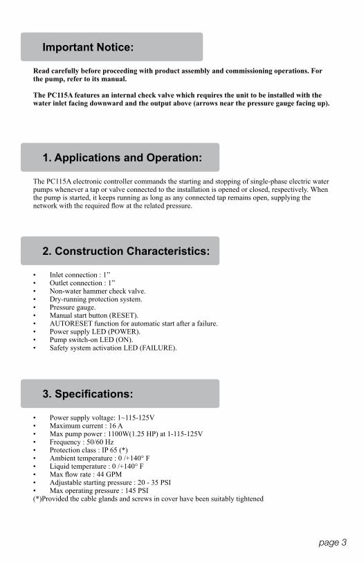
Important Notice:
1. Applications and Operation:
2. Construction Characteristics:
3. Specifications:
Read carefully before proceeding with product assembly and commissioning operations. For the pump, refer to its manual.
The PC115A features an internal check valve which requires the unit to be installed with the water inlet facing downward and the output above (arrows near the pressure gauge facing up).
The PC115A electronic controller commands the starting and stopping of single-phase electric water pumps whenever a tap or valve connected to the installation is opened or closed, respectively. When the pump is started, it keeps running as long as any connected tap remains open, supplying the network with the required flow at the related pressure.
• Inlet connection : 1”• Outlet connection : 1”• Non-water hammer check valve.• Dry-running protection system.• Pressure gauge.• Manual start button (RESET).• AUTORESET function for automatic start after a failure.• Power supply LED (POWER).• Pump switch-on LED (ON).• Safety system activation LED (FAILURE).
• Power supply voltage: 1~115-125V• Maximum current : 16 A• Max pump power : 1100W(1.25 HP) at 1-115-125V• Frequency : 50/60 Hz• Protection class : IP 65 (*)• Ambient temperature : 0 /+140° F• Liquid temperature : 0 /+140° F• Max flow rate : 44 GPM• Adjustable starting pressure : 20 - 35 PSI• Max operating pressure : 145 PSI(*)Provided the cable glands and screws in cover have been suitably tightened
page 4
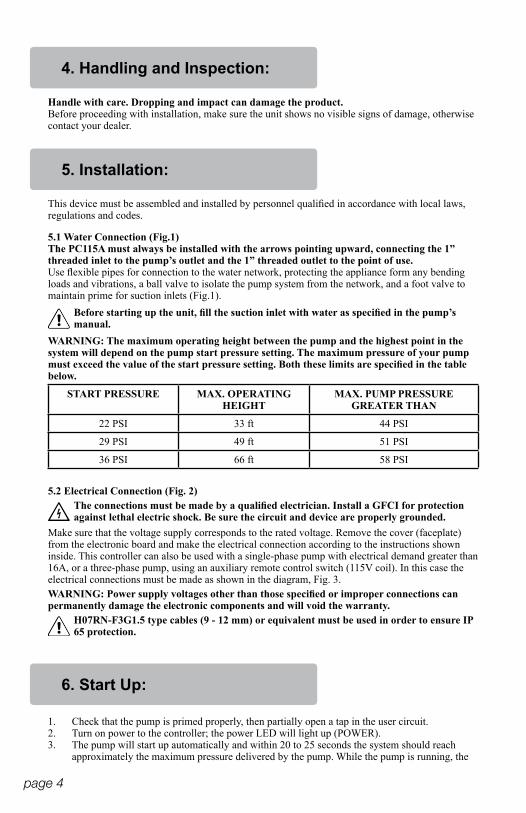
4. Handling and Inspection:
5. Installation:
6. Start Up:
Handle with care. Dropping and impact can damage the product.Before proceeding with installation, make sure the unit shows no visible signs of damage, otherwise contact your dealer.
Make sure that the voltage supply corresponds to the rated voltage. Remove the cover (faceplate)from the electronic board and make the electrical connection according to the instructions shown inside. This controller can also be used with a single-phase pump with electrical demand greater than 16A, or a three-phase pump, using an auxiliary remote control switch (115V coil). In this case the electrical connections must be made as shown in the diagram, Fig. 3.
5.2 Electrical Connection (Fig. 2)
5.1 Water Connection (Fig.1)The PC115A must always be installed with the arrows pointing upward, connecting the 1” threaded inlet to the pump’s outlet and the 1” threaded outlet to the point of use.Use flexible pipes for connection to the water network, protecting the appliance form any bending loads and vibrations, a ball valve to isolate the pump system from the network, and a foot valve to maintain prime for suction inlets (Fig.1).
START PRESSURE MAX. OPERATING HEIGHT
MAX. PUMP PRESSURE GREATER THAN
22 PSI 33 ft 44 PSI
29 PSI 49 ft 51 PSI
36 PSI 66 ft 58 PSI
WARNING: The maximum operating height between the pump and the highest point in the system will depend on the pump start pressure setting. The maximum pressure of your pump must exceed the value of the start pressure setting. Both these limits are specified in the table below.
WARNING: Power supply voltages other than those specified or improper connections can permanently damage the electronic components and will void the warranty.
This device must be assembled and installed by personnel qualified in accordance with local laws, regulations and codes.
Before starting up the unit, fill the suction inlet with water as specified in the pump’s manual.
H07RN-F3G1.5 type cables (9 - 12 mm) or equivalent must be used in order to ensure IP 65 protection.
The connections must be made by a qualified electrician. Install a GFCI for protectionagainst lethal electric shock. Be sure the circuit and device are properly grounded.
1. Check that the pump is primed properly, then partially open a tap in the user circuit.2. Turn on power to the controller; the power LED will light up (POWER).3. The pump will start up automatically and within 20 to 25 seconds the system should reach
approximately the maximum pressure delivered by the pump. While the pump is running, the
page 5
corresponding LED (ON) willremain illuminated.4. Close the tap mentioned under step (1). After 10-12 seconds the pump will stop running, but
the power supply LED (POWER) will remain lit. Any malfunctions occurring after these operations will be caused by improper priming or failure to prime.
7. Starting Pressure Adjustment: (P. Start):
8. Automatic Reset Function:
9. Troubleshooting:
The pump controller is factory set to start with a minimum pressure of 21.75 PSI (1.5 bar). This pressure can be increased up to 36.25 PSI (2.5 bar) by rotating the screw found at the back of the cone-shaped end of the device, (see Fig. 4).To set the pump start pressure:1. Read the pressure indicated by the gauge when the pump is started.2. Disconnect the power supply.3. Open a tap to discharge the pressure.4. Adjust the screw clockwise to increase (or counter-clockwise to decrease) the start pressure.5. Supply power to the the controller; if you are not satisfied with the adjustment, repeat the
operations described above until you obtain the desired pressure value.NOTE: The maximum pressure of the pump (closing contact pressure) and the minimum start pressure must comply with the values shown in the table under paragraph 5.1 otherwise the controller will go into FAILURE mode.
If the device goes into failure mode, the automatic reset function will execute a series of automatic starts to attempt to restore operation without any manual intervention via the RESET button.The system operates as follows: The appliance is in failure mode due to water failure, for example; after 5 minutes in this condition the system will do a 25-second RESET, attempting to prime the pump. If the system is able to prime the pump, the failure will disappear and the pump will be ready to operate. However, if the failure persists, the system will do another RESET after 30 minutes, and will continue in this manner systematically every 30 minutes for 24 hours. If the failure still persists after all these attempts, the system will remain in this condition until the problem has been resolved by manual intervention or when power is recycled.
1.- THE PUMP DOES NOT STOP:A) Water loss exceeding 0.8 gpm. Make sure that all the taps along the pipeline are closed and that there are no leaks.B) The electrical connection is incorrect: refer to the instructions in Fig. 2. C) Electronic board malfunction: replace the electronic board.2.- THE PUMP DOES NOT START:A) The pump is not primed; dry-run protection is active and the FAILURE LED is on: prime the water pipe and check by pressing the manual start button (RESET).B) The pump has shut down: the safety system has stepped in and the FAILURE LED is on. If you press the manual start button (RESET) and the LED (ON) lights up; if the pump does not start test the output with another device such as a lamp.C) Electronic board malfunction: disconnect the pump from the electrical mains and re-connect it; the pump should start, if it does not replace the controller.D) No power supply: check the electrical connections, the POWER LED must be illuminated.E) The pump delivers insufficient pressure, the safety system has stepped in and the corresponding LED (FAILURE) is illuminated: make sure that the pump pressure corresponds to the pressure value specified in the relevant table in section 5.1.F) Air is entering the pump through the suction side: the pressure is well below normal, with
page 6
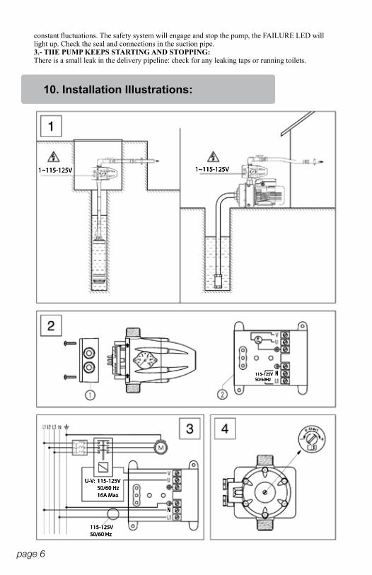
constant fluctuations. The safety system will engage and stop the pump, the FAILURE LED will light up. Check the seal and connections in the suction pipe.3.- THE PUMP KEEPS STARTING AND STOPPING:There is a small leak in the delivery pipeline: check for any leaking taps or running toilets.
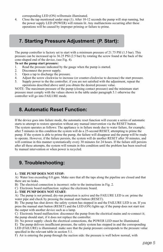
115-125V50/60 Hz
115-125V50/60 Hz16A Max
U-V:
115-125V50/60Hz
1~115-125V 1~115-125V
N
N
10. Installation Illustrations:
page 7
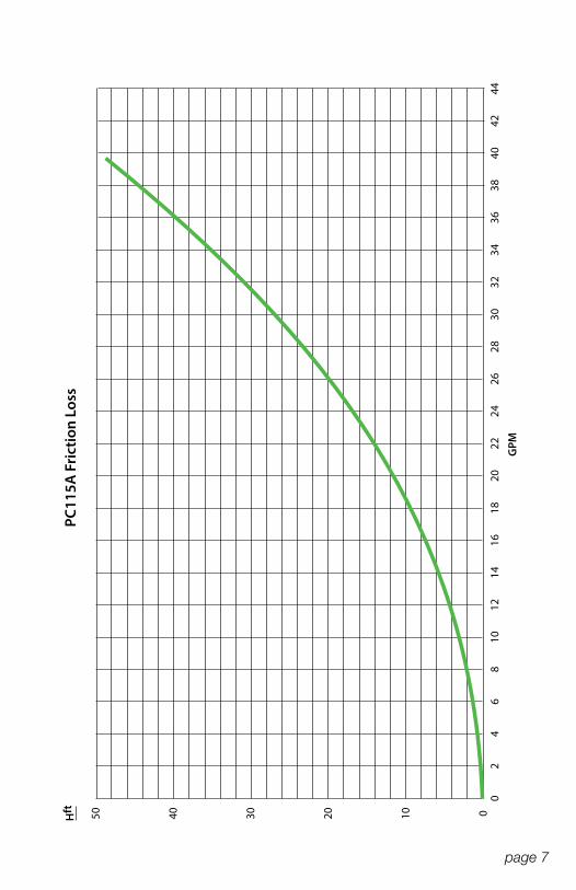
3432
3028
2644
4240
3836
2422
2018
1614
1210
86
42
0
GPM
3050 40 20 10 0Hft
PC11
5A F
rict
ion
Loss

Rev. 012115
®
PC115A Pump Controller