Embed Size (px)
Citation preview
P-DUKE Technology Co., Ltd.
www.pduke.com 2017.03.27 Page 1
Railway Automation Datacom
IPC Industry Measurement
Telecom Automobile Boat
Charger Medical PV
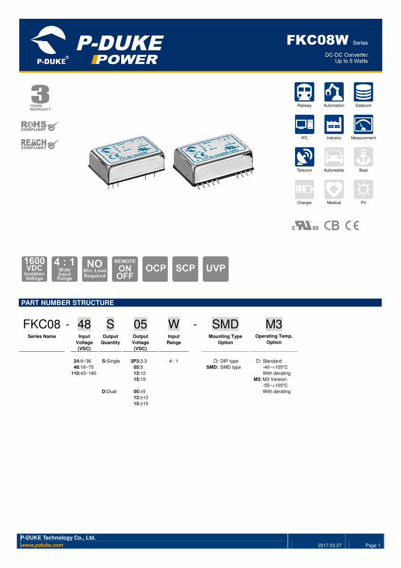
PART NUMBER STRUCTURE
FKC08 - 48 S 05 W - SMD M3 Series Name Input Output Output Input Mounting Type Operating Temp.
Voltage Quantity Voltage Range Option Option
(VDC) (VDC) 24:9~36 S:Single 3P3:3.3 4 : 1 ����: DIP type ����: Standard
48:18~75 05:5 SMD: SMD type -40~+105℃
110:43~160 12:12 With derating
15:15 M3: M3 Version
-55~+105℃
D:Dual 05:±5 With derating
12:±12
15:±15
FKC08W Series
P-DUKE Technology Co., Ltd.
www.pduke.com 2017.03.27 Page 2
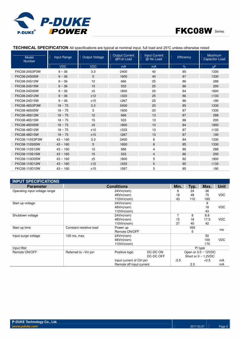
TECHNICAL SPECIFICATION All specifications are typical at nominal input, full load and 25℃ unless otherwise noted
Input Range Output Voltage Output Current
@Full Load Input Current @ No Load
Efficiency Maximum
Capacitor Load Model
Number
VDC VDC mA mA % μF
FKC08-24S3P3W 9 ~ 36 3.3 2400 40 85 1330
FKC08-24S05W 9 ~ 36 5 1600 40 87 1330
FKC08-24S12W 9 ~ 36 12 666 25 86 288
FKC08-24S15W 9 ~ 36 15 533 25 86 200
FKC08-24D05W 9 ~ 36 ±5 ±800 20 84 ±900
FKC08-24D12W 9 ~ 36 ±12 ±333 25 86 ±133
FKC08-24D15W 9 ~ 36 ±15 ±267 25 86 ±90
FKC08-48S3P3W 18 ~ 75 3.3 2400 20 85 1330
FKC08-48S05W 18 ~ 75 5 1600 20 87 1330
FKC08-48S12W 18 ~ 75 12 666 13 87 288
FKC08-48S15W 18 ~ 75 15 533 13 88 200
FKC08-48D05W 18 ~ 75 ±5 ±800 10 84 ±900
FKC08-48D12W 18 ~ 75 ±12 ±333 13 87 ±133
FKC08-48D15W 18 ~ 75 ±15 ±267 13 87 ±90
FKC08-110S3P3W 43 ~ 160 3.3 2400 8 84 1330
FKC08-110S05W 43 ~ 160 5 1600 8 85 1330
FKC08-110S12W 43 ~ 160 12 666 4 86 288
FKC08-110S15W 43 ~ 160 15 533 4 86 200
FKC08-110D05W 43 ~ 160 ±5 ±800 5 82 ±900
FKC08-110D12W 43 ~ 160 ±12 ±333 5 85 ±133
FKC08-110D15W 43 ~ 160 ±15 ±267 5 85 ±90
INPUT SPECIFICATIONS
Parameter Conditions Min. Typ. Max. Unit Operating input voltage range
24Vin(nom)
48Vin(nom)
110Vin(nom)
9
18
43
24
48
110
36
75
160
VDC
Start up voltage 24Vin(nom)
48Vin(nom)
110Vin(nom)
9
18
43
VDC
Shutdown voltage 24Vin(nom)
48Vin(nom)
110Vin(nom)
7
15
37
8
16
40
8.8
17.5
42
VDC
Start up time Constant resistive load Power up
Remote ON/OFF
450
5 ms
Input surge voltage 100 ms, max. 24Vin(nom)
48Vin(nom)
110Vin(nom)
50
100
170
VDC
Input filter Pi type
Referred to –Vin pin Positive logic DC-DC ON Open or 3.0 ~ 12VDC Remote ON/OFF
DC-DC OFF Short or 0 ~ 1.2VDC
Input current of Ctrl pin -0.5 +0.5 mA
Remote off input current 2.5 mA
FKC08W Series
P-DUKE Technology Co., Ltd.
www.pduke.com 2017.03.27 Page 3
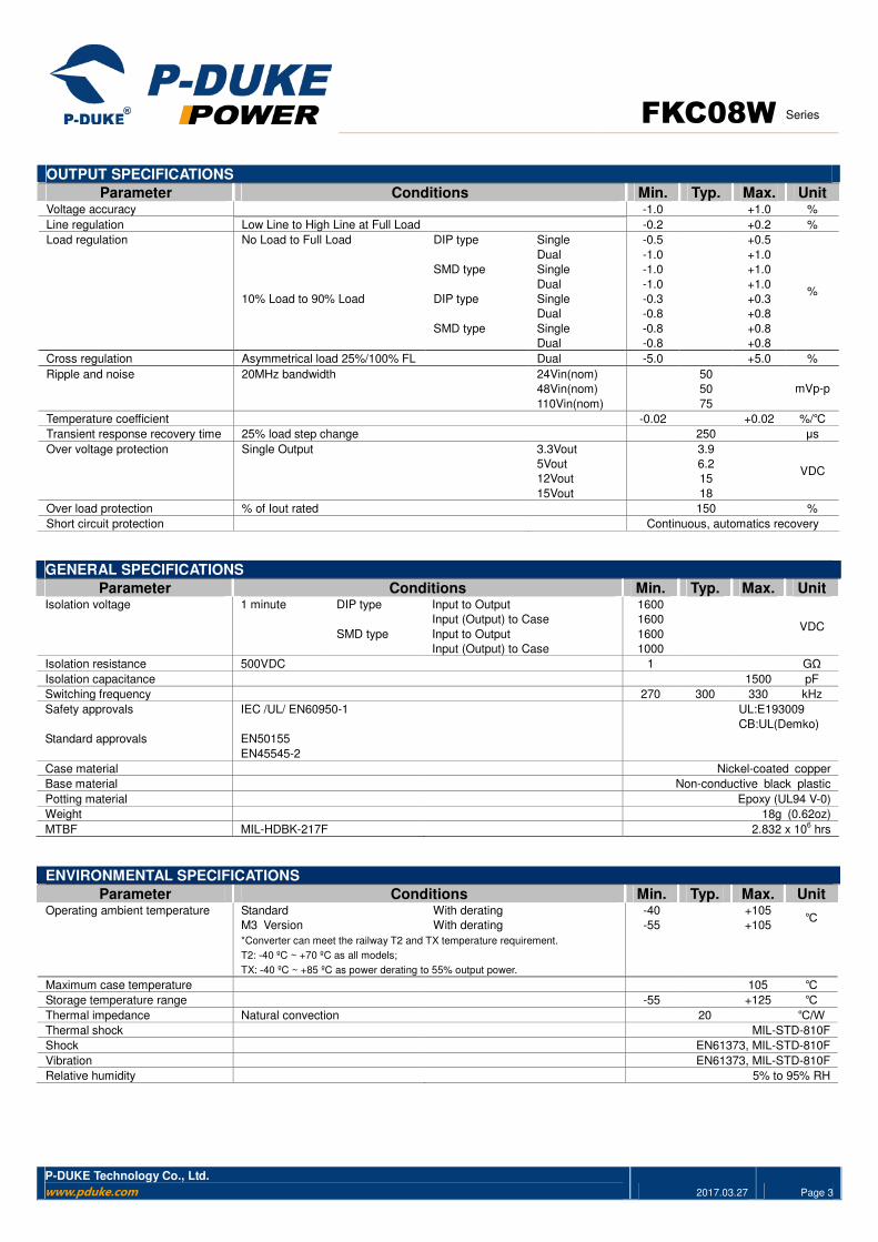
OUTPUT SPECIFICATIONS
Parameter Conditions Min. Typ. Max. Unit Voltage accuracy -1.0 +1.0 %
Line regulation Low Line to High Line at Full Load -0.2 +0.2 %
DIP type Single -0.5 +0.5
Dual -1.0 +1.0
SMD type Single -1.0 +1.0
No Load to Full Load
Dual -1.0 +1.0
DIP type Single -0.3 +0.3
Dual -0.8 +0.8
SMD type Single -0.8 +0.8
Load regulation
10% Load to 90% Load
Dual -0.8 +0.8
%
Cross regulation Asymmetrical load 25%/100% FL Dual -5.0 +5.0 %
24Vin(nom) 50
48Vin(nom) 50
Ripple and noise 20MHz bandwidth
110Vin(nom) 75
mVp-p
Temperature coefficient -0.02 +0.02 %/℃
Transient response recovery time 25% load step change 250 μs
3.3Vout 3.9
5Vout 6.2
12Vout 15
Over voltage protection Single Output
15Vout 18
VDC
Over load protection % of Iout rated 150 %
Short circuit protection Continuous, automatics recovery
GENERAL SPECIFICATIONS
Parameter Conditions Min. Typ. Max. Unit 1 minute DIP type Input to Output 1600
Input (Output) to Case 1600
SMD type Input to Output 1600
Isolation voltage
Input (Output) to Case 1000
VDC
Isolation resistance 500VDC 1 GΩ
Isolation capacitance 1500 pF
Switching frequency 270 300 330 kHz
Safety approvals IEC /UL/ EN60950-1 UL:E193009
CB:UL(Demko)
Standard approvals EN50155
EN45545-2
Case material Nickel-coated copper
Base material Non-conductive black plastic
Potting material Epoxy (UL94 V-0)
Weight 18g (0.62oz)
MTBF MIL-HDBK-217F 2.832 x 10⁶ hrs
ENVIRONMENTAL SPECIFICATIONS Parameter Conditions Min. Typ. Max. Unit
Standard With derating -40 +105
M3 Version With derating -55 +105 ℃ Operating ambient temperature
*Converter can meet the railway T2 and TX temperature requirement.
T2: -40 ºC ~ +70 ºC as all models;
TX: -40 ºC ~ +85 ºC as power derating to 55% output power.
Maximum case temperature 105 ℃ Storage temperature range -55 +125 ℃
Thermal impedance Natural convection 20 ℃/W Thermal shock MIL-STD-810F
Shock EN61373, MIL-STD-810F
Vibration EN61373, MIL-STD-810F
Relative humidity 5% to 95% RH
FKC08W Series
P-DUKE Technology Co., Ltd.
www.pduke.com 2017.03.27 Page 4
EMC SPECIFICATIONS Parameter Conditions Level
EMI EN55032, EN55011 With external components Class A,Class B
ESD EN61000-4-2 Air ± 8kV and Contact ± 6kV Perf. Criteria A
Radiated immunity EN61000-4-3 20 V/m Perf. Criteria A
EN61000-4-4 ± 2kV
24Vin
48Vin
With an external input filter capacitor (Nippon chemi-con KY series, 220μF/100V)
Fast transient
110 Vin With an external input filter capacitor
(Nippon chemi-con KXJ series, 150μF/200V)
Perf. Criteria A
EN61000-4-5 EN55024 ±2kV and EN50155 ±2kV
24Vin
48Vin
With an external input filter capacitor (Nippon chemi-con KY series, 220μF/100V)
Surge
110 Vin With an external input filter capacitor
(Nippon chemi-con KXJ series, 150μF/200V)
Perf. Criteria A
Conducted immunity EN61000-4-6 10 Vr.m.s Perf. Criteria A
Power frequency magnetic field EN61000-4-8 100A/m continuous; 1000A/m 1 second Perf. Criteria A
CAUTION: This power module is not internally fused. An input line fuse must always be used
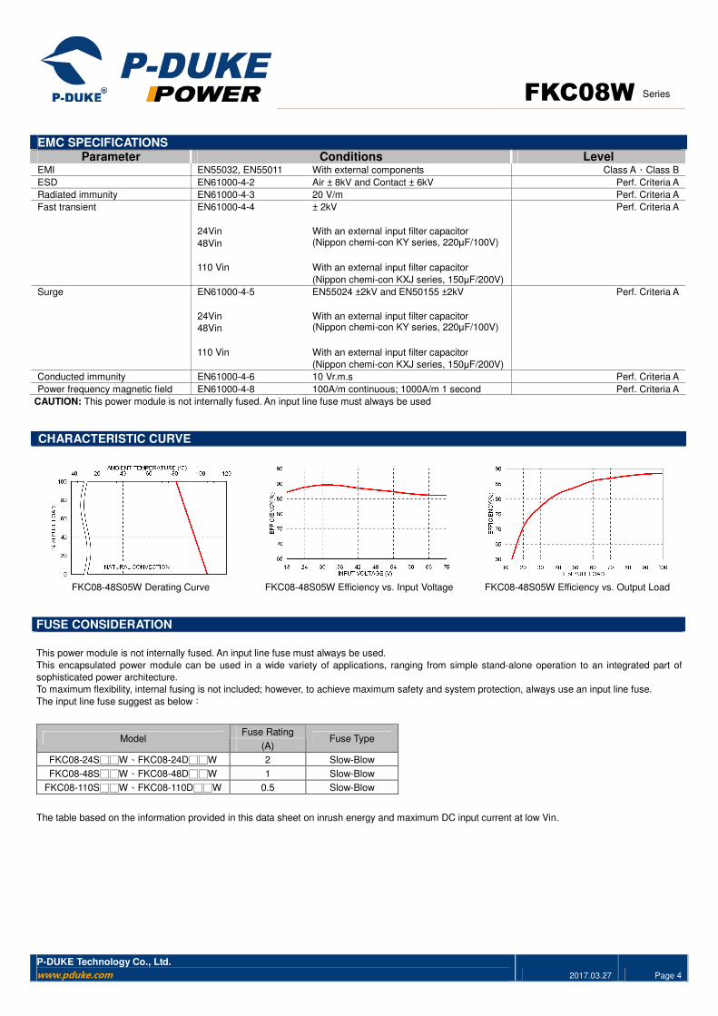
CHARACTERISTIC CURVE
FKC08-48S05W Derating Curve FKC08-48S05W Efficiency vs. Input Voltage FKC08-48S05W Efficiency vs. Output Load
FUSE CONSIDERATION
This power module is not internally fused. An input line fuse must always be used.
This encapsulated power module can be used in a wide variety of applications, ranging from simple stand-alone operation to an integrated part of
sophisticated power architecture.
To maximum flexibility, internal fusing is not included; however, to achieve maximum safety and system protection, always use an input line fuse.
The input line fuse suggest as below:
Fuse Rating Model
(A) Fuse Type
FKC08-24S□□W、FKC08-24D□□W 2 Slow-Blow
FKC08-48S□□W、FKC08-48D□□W 1 Slow-Blow
FKC08-110S□□W、FKC08-110D□□W 0.5 Slow-Blow
The table based on the information provided in this data sheet on inrush energy and maximum DC input current at low Vin.
FKC08W Series
P-DUKE Technology Co., Ltd.
www.pduke.com 2017.03.27 Page 5
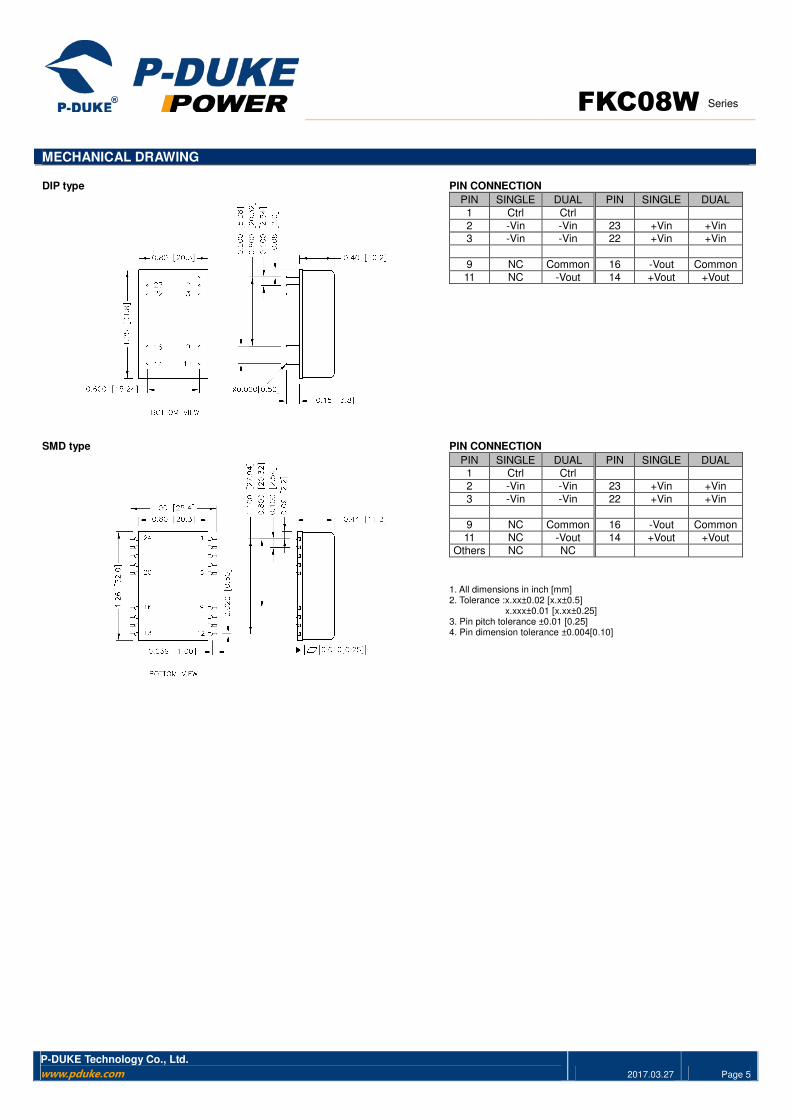
MECHANICAL DRAWING DIP type PIN CONNECTION
PIN SINGLE DUAL PIN SINGLE DUAL
1 Ctrl Ctrl
2 -Vin -Vin 23 +Vin +Vin 3 -Vin -Vin 22 +Vin +Vin
9 NC Common 16 -Vout Common
11 NC -Vout 14 +Vout +Vout
SMD type PIN CONNECTION
PIN SINGLE DUAL PIN SINGLE DUAL
1 Ctrl Ctrl
2 -Vin -Vin 23 +Vin +Vin
3 -Vin -Vin 22 +Vin +Vin
9 NC Common 16 -Vout Common
11 NC -Vout 14 +Vout +Vout
Others NC NC
1. All dimensions in inch [mm] 2. Tolerance :x.xx±0.02 [x.x±0.5]
x.xxx±0.01 [x.xx±0.25] 3. Pin pitch tolerance ±0.01 [0.25] 4. Pin dimension tolerance ±0.004[0.10]
FKC08W Series
P-DUKE Technology Co., Ltd.
Tel
Fax
Web
Add
+886-4-2359-0668
+886-4-2359-1337
www.pduke.com
No. 36, 22nd
Rd., Taichung Industrial Park,
Taichung, Taiwan, R.O.C.
2017.03.27 Page 6
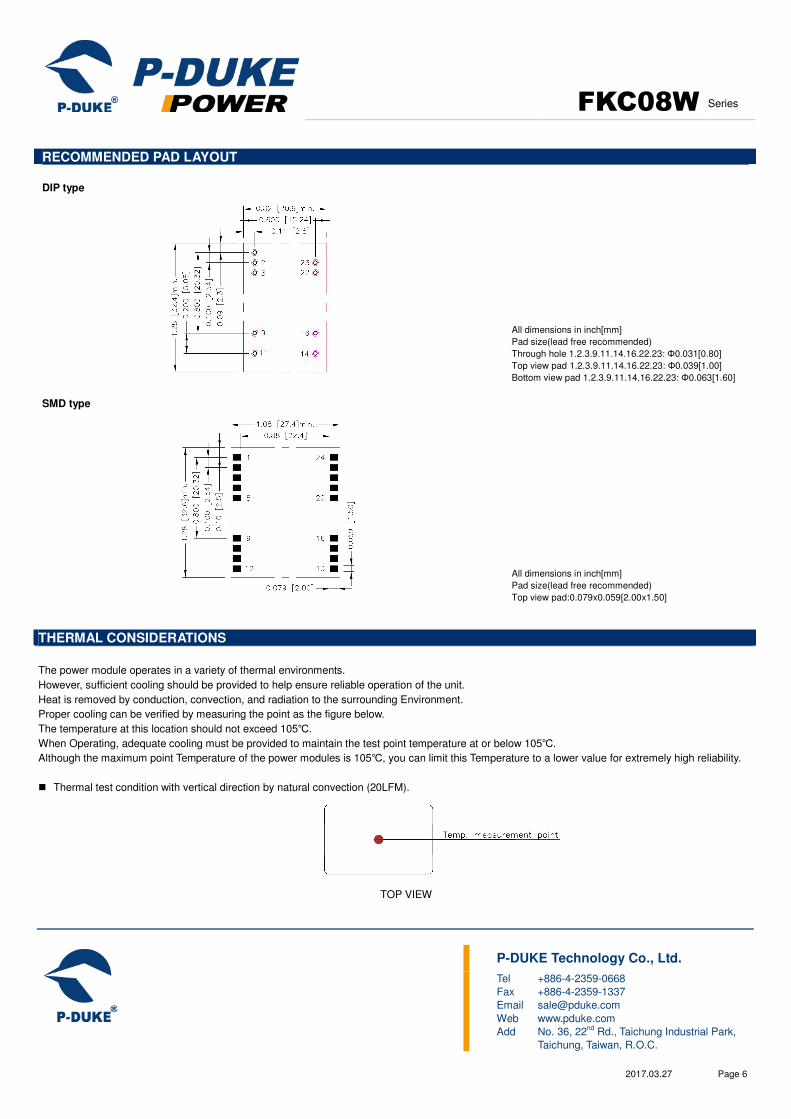
RECOMMENDED PAD LAYOUT DIP type
All dimensions in inch[mm]
Pad size(lead free recommended)
Through hole 1.2.3.9.11.14.16.22.23: Φ0.031[0.80]
Top view pad 1.2.3.9.11.14.16.22.23: Φ0.039[1.00]
Bottom view pad 1.2.3.9.11.14.16.22.23: Φ0.063[1.60]
SMD type
All dimensions in inch[mm]
Pad size(lead free recommended)
Top view pad:0.079x0.059[2.00x1.50]
THERMAL CONSIDERATIONS
The power module operates in a variety of thermal environments.
However, sufficient cooling should be provided to help ensure reliable operation of the unit.
Heat is removed by conduction, convection, and radiation to the surrounding Environment.
Proper cooling can be verified by measuring the point as the figure below.
The temperature at this location should not exceed 105℃.
When Operating, adequate cooling must be provided to maintain the test point temperature at or below 105℃.
Although the maximum point Temperature of the power modules is 105℃, you can limit this Temperature to a lower value for extremely high reliability.
� Thermal test condition with vertical direction by natural convection (20LFM).
TOP VIEW