Embed Size (px)
Citation preview

Railway Automation Datacom
IPC Industry Measurement
Telecom Charger Automobile
Boat Medical PV
PART NUMBER STRUCTURE
WAF300 - 48 S 12 W - N S DR Series Name
Input Output Output Input Remote Control Load Share Assembly
Voltage Quantity Voltage Range Option Option Option (VDC) (VDC)
48:18~75 S:Single 12:12 4:1 :Positive logic, : None : Wall mounted
110:43~160 15:15 N:Negative logic S: Load Share DR: Din rail type
24:24
28:28
48:48
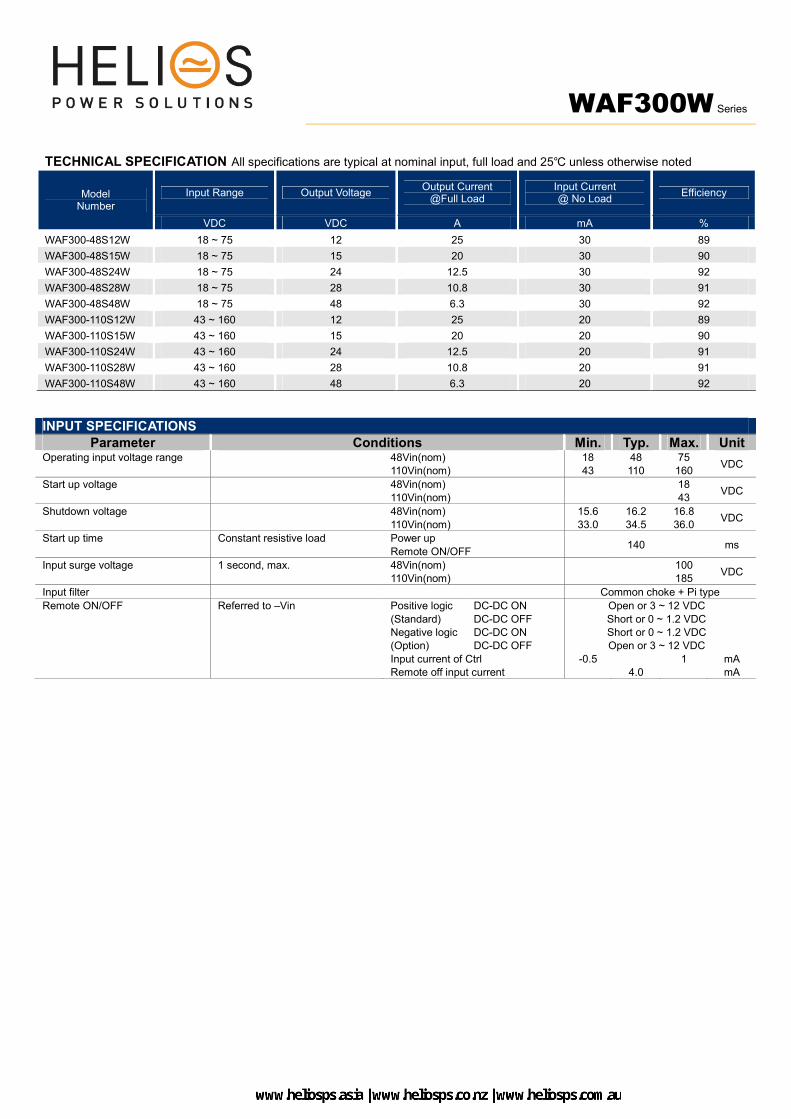
WAF300W Series
TECHNICAL SPECIFICATION All specifications are typical at nominal input, full load and 25℃ unless otherwise noted
Model Number
Input Range Output Voltage Output Current
@Full Load Input Current @ No Load
Efficiency
VDC VDC A mA %
WAF300-48S12W 18 ~ 75 12 25 30 89
WAF300-48S15W 18 ~ 75 15 20 30 90
WAF300-48S24W 18 ~ 75 24 12.5 30 92
WAF300-48S28W 18 ~ 75 28 10.8 30 91
WAF300-48S48W 18 ~ 75 48 6.3 30 92
WAF300-110S12W 43 ~ 160 12 25 20 89
WAF300-110S15W 43 ~ 160 15 20 20 90
WAF300-110S24W 43 ~ 160 24 12.5 20 91
WAF300-110S28W 43 ~ 160 28 10.8 20 91
WAF300-110S48W 43 ~ 160 48 6.3 20 92
INPUT SPECIFICATIONS Parameter Conditions Min. Typ. Max. Unit
Operating input voltage range 48Vin(nom) 110Vin(nom)
18 43
48 110
75 160
VDC
Start up voltage 48Vin(nom) 110Vin(nom)
18 43
VDC
Shutdown voltage 48Vin(nom) 110Vin(nom)
15.6 33.0
16.2 34.5
16.8 36.0
VDC
Start up time Constant resistive load Power up
Remote ON/OFF 140 ms
Input surge voltage 1 second, max. 48Vin(nom) 110Vin(nom)
100 185
VDC
Input filter Common choke + Pi type
Remote ON/OFF Referred to –Vin Positive logic
(Standard)
DC-DC ON
DC-DC OFF
Open or 3 ~ 12 VDC
Short or 0 ~ 1.2 VDC Negative logic (Option)
DC-DC ON DC-DC OFF
Short or 0 ~ 1.2 VDC Open or 3 ~ 12 VDC
Input current of Ctrl -0.5 1 mA Remote off input current 4.0 mA

WAF300W Series
OUTPUT SPECIFICATIONS
Parameter Conditions Min. Typ. Max. Unit Rated Output Power Normal Vout and Iout 300 W
Voltage accuracy -1 +1 %
Line regulation Low Line to High Line at Full Load -0.2 +0.2 %
Load regulation No Load to Full Load -0.5 +0.5 %
Voltage adjustability Maximum output deviation is inclusive of remote sense -20 +20 %
Remote sense % of Vout(nom) If remote sense is not being used, Sense terminals should be connected to corresponding polarity Vout terminals.
10 %
Ripple and noise Measured by 20MHz bandwidth
12Vout, 15Vout
24Vout, 28Vout 48Vout
100
200 300
125
250 350
mVp-p
Temperature coefficient -0.02 +0.02 %/℃
Transient response recovery time 25% load step change 250 μs
Over voltage protection % of Vout(nom); Latch mode 125 140 %
Over load protection % of Iout rated; C.C. mode
* “C.C. Mode” is “Constant Current Mode” and test by nominal input. 105 115 %
Short circuit protection C.C. mode, automatics recovery
Load Share accuracy Full Load *Connect the LS (Terminal 11) from each converter.
The converter can parallel to increase output current. It has internal load share
function in this converter. (This function only for suffix “-S” part.)
-10 +10 %
GENERAL SPECIFICATIONS Parameter Conditions Min. Typ. Max. Unit
Isolation voltage 1 minute Input to Output Input (Output) to Case
3000 1500
VAC
Isolation resistance 500VDC 1 GΩ
Isolation capacitance 14000 pF
Switching frequency 48VDC input 110VDC input
203 180
225 200
248 220
kHz
Safety approvals IEC/ UL/ EN60950-1
IEC /UL/ EN62368-1 UL508
UL:E193009
CB:UL(Demko)
Standard approvals EN50155 EN45545-2
Case material Aluminum
Potting material Silicone (UL94 V-0)
Weight 900g (31.74oz.)
MTBF MIL-HDBK-217F, Full load 1.490x 10⁵ hrs
ENVIRONMENTAL SPECIFICATIONS Parameter Conditions Min. Typ. Max. Unit
Operating case temperature -40 +100 ℃
Maximum case temperature +100 ℃
Over temperature protection +105 ℃
Storage temperature range -40 +105 ℃
Thermal impedance Mounted on the iron base-plate * The iron base-plate dimension is 19” X 5.25” X 0.063”
(The height is EIA standard 3U).
1.1 ℃/W
Thermal shock MIL-STD-810F
Shock EN61373, MIL-STD-810F
Vibration EN61373, MIL-STD-810F
Relative humidity 5% to 95% RH

WAF300W Series
EMC SPECIFICATIONS
Parameter Conditions Level EMI EN55011, EN55032 Without external component Radiation
Conduction
Class A
ESD EN61000-4-2 Air ± 8kV and Contact ± 6kV Perf. Criteria A
Radiated immunity EN61000-4-3 20V/m Perf. Criteria A
Fast transient EN61000-4-4 ± 2kV Perf. Criteria A
Surge EN61000-4-5 EN55024 ±1kV and EN50155 ±2kV Perf. Criteria A
Conducted immunity EN61000-4-6 10Vr.m.s Perf. Criteria A
Power frequency magnetic field EN61000-4-8 100A/m continuous; 1000A/m 1 second Perf. Criteria A
CAUTION: This power module is not internally fused. An input line fuse must always be used.
CHARACTERISTIC CURVE
WAF300-48S□□W Derating Curve
WAF300-48S□□W Derating Curve With 3U Iron Base-Plate
WAF300-110S□□W Derating Curve
WAF300-110S□□W Derating Curve
With 3U Iron Base-Plate WAF300-48S12W
Efficiency vs. Output Load WAF300-48S12W
Efficiency vs. Input Voltage
FUSE CONSIDERATION
This power module is not internally fused. An input line fuse must always be used. This encapsulated power module can be used in a wide variety of applications, ranging from simple stand-alone operation to an integrated part of
sophisticated power architecture. To maximum flexibility, internal fusing is not included; however, to achieve maximum safety and system protection, always use an input line fuse. The input line fuse suggest as below:
Model Fuse Rating
Fuse Type (A)
WAF300-48S□□W 25 Fast-Acting
WAF300-110S□□W 12 Fast-Acting
The table based on the information provided in this data sheet on inrush energy and maximum DC input current at low Vin.

WAF300W Series
MECHANICAL DRAWING
WALL MOUNTED TYPE
TERMINAL CONNECTION
Terminal Define Recommend
Matching Wire
1, 2 +Vin 12-16 AWG
3, 4 -Vin 12-16 AWG
5 Ctrl 12-28AWG
6, 7 + Vout 12-16 AWG
8, 9 - Vout 12-16 AWG
10 + Sense 20-28 AWG
11 LS (option) 20-28 AWG
12 - Sense 20-28 AWG * The current rating of the terminal block is 15 amps/pole.
* Using 2 poles at the same time when operating is recommended if the total current are more than 15 amps or choose optional 2-way splitter. (Please refer to the diagram
below) * Input voltage vs. Input terminal, refer to the table below.
Output power Input voltage Input terminal
300W; Full load 23V≧ 1 pole
<23V 2 poles
400W; C.C. mode 32V≧ 1 pole
<32V 2 poles
1. All dimensions in inch [mm]
2. Tolerance : x.xx±0.02 [x.x±0.5]
x.xxx±0.010 [x.xx±0.25]
3. The screw locked torque: MAX 14kgf-cm/1.37N.m
DIN RAIL TYPE
WAF300W Series
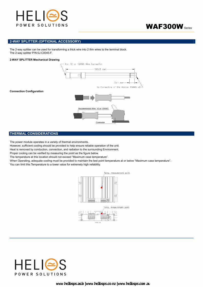
2-WAY SPLITTER (OPTIONAL ACCESSORY)
The 2-way splitter can be used for transforming a thick wire into 2 thin wires to the terminal block. The 2-way splitter P/N:5J-C0045-F.
2-WAY SPLITTER Mechanical Drawing
Connection Configuration
THERMAL CONSIDERATIONS
The power module operates in a variety of thermal environments.
However, sufficient cooling should be provided to help ensure reliable operation of the unit.
Heat is removed by conduction, convection, and radiation to the surrounding Environment.
Proper cooling can be verified by measuring the point as the figure below.
The temperature at this location should not exceed “Maximum case temperature”.
When Operating, adequate cooling must be provided to maintain the test point temperature at or below “Maximum case temperature”.
You can limit this Temperature to a lower value for extremely high reliability.