Embed Size (px)
Citation preview
RAEGE Project Update: Yebes Observatory Broadband ReceiverReady for VGOS
IGN Yebes Observatory staff
Abstract An update of the deployment and activi-ties at the Spanish/Portuguese RAEGE project (“At-lantic Network of Geodynamical and Space Stations”)is presented. While regular observations with the Yebesradio telescope are on-going, technological develop-ments about receivers for VGOS are progressing at theYebes laboratories.
Keywords VGOS, broadband
1 Introduction
The Yebes Observatory of the Spanish Centro de De-sarrollos Tecnologicos in the National GeographicalInstitute (IGN CDT) has developed an ultra-low noiseand broadband (2–14 GHz) cryogenic receiver forthe VLBI Global Observing System (VGOS) projectwhich has been installed in the new 13.2-m radiotelescope (see Figure 1).
The 13.2-m radio telescope is an elevation-over-azimuth turning-head antenna with a ring-focus opti-cal design and fast moving capabilities. It has been re-cently upgraded with a cladding in the back-up struc-ture to reduce thermal gradients and extend its operat-ing frequency.
Instituto Geografico Nacional (IGN, Spain)
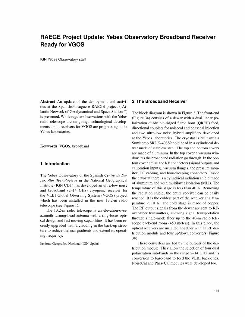
2 The Broadband Receiver
The block diagram is shown in Figure 2. The front-end(Figure 3a) consists of a dewar with a dual linear po-larization quadruple-ridged flared horn (QRFH) feed,directional couplers for noisecal and phasecal injectionand two ultra-low noise hybrid amplifiers developedat the Yebes laboratories. The cryostat is built over aSumitomo SRDK-408S2 cold head in a cylindrical de-war made of stainless steel. The top and bottom coversare made of aluminum. In the top cover a vacuum win-dow lets the broadband radiation go through. In the bot-tom cover are all the RF connectors (signal outputs andcalibration inputs), vacuum flanges, the pressure mon-itor, DC cabling, and housekeeping connectors. Insidethe cryostat there is a cylindrical radiation shield madeof aluminum and with multilayer isolation (MLI). Thetemperature of this stage is less than 40 K. Removingthe radiation shield, the entire receiver can be easilyreached. It is the coldest part of the receiver at a tem-perature < 10 K. The cold stage is made of copper.The RF output signals from the dewar are sent to RF-over-fiber transmitters, allowing signal transportationthrough single-mode fiber up to the 40-m radio tele-scope back-end room (450 meters). In this place, theoptical receivers are installed, together with an RF dis-tribution module and four up/down converters (Figure3b).
These converters are fed by the outputs of the dis-tribution module. They allow the selection of four dualpolarization sub-bands in the range 2–14 GHz and itsconversion to base-band to feed the VLBI back-ends.NoiseCal and PhaseCal modules were developed too.
135
136 IGN Yebes Observatory staff
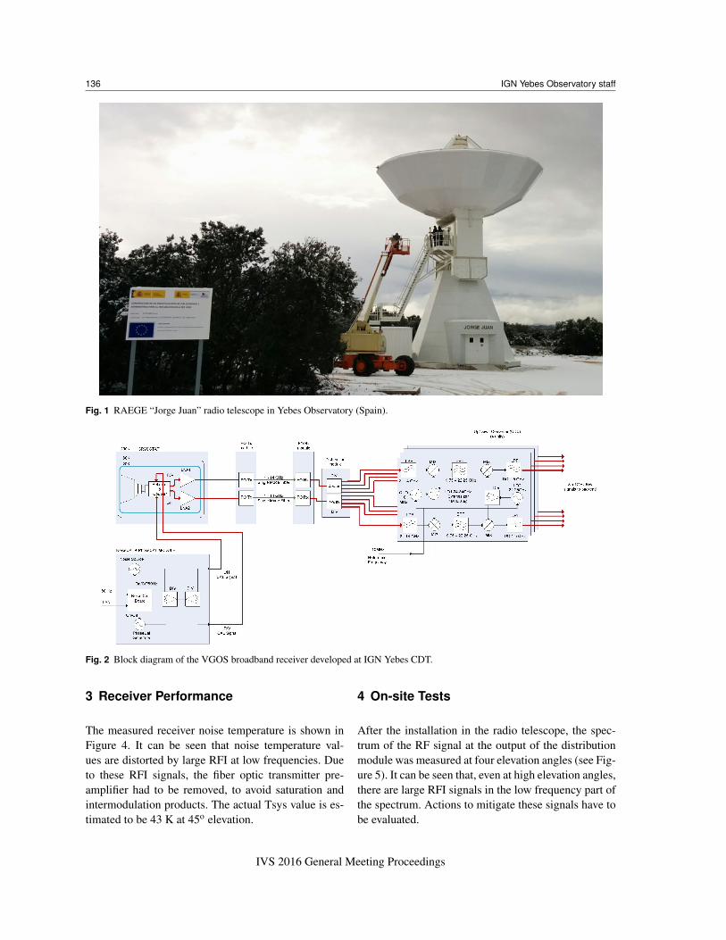
Fig. 1 RAEGE “Jorge Juan” radio telescope in Yebes Observatory (Spain).
Fig. 2 Block diagram of the VGOS broadband receiver developed at IGN Yebes CDT.
3 Receiver Performance
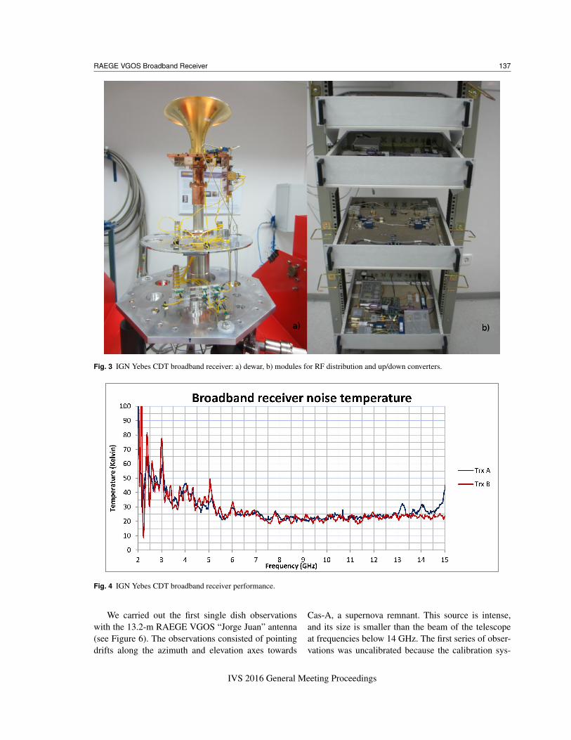
The measured receiver noise temperature is shown inFigure 4. It can be seen that noise temperature val-ues are distorted by large RFI at low frequencies. Dueto these RFI signals, the fiber optic transmitter pre-amplifier had to be removed, to avoid saturation andintermodulation products. The actual Tsys value is es-timated to be 43 K at 45o elevation.
4 On-site Tests
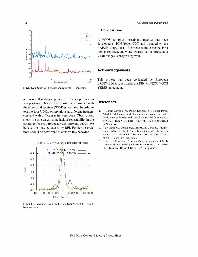
After the installation in the radio telescope, the spec-trum of the RF signal at the output of the distributionmodule was measured at four elevation angles (see Fig-ure 5). It can be seen that, even at high elevation angles,there are large RFI signals in the low frequency part ofthe spectrum. Actions to mitigate these signals have tobe evaluated.
IVS 2016 General Meeting Proceedings
RAEGE VGOS Broadband Receiver 137
Fig. 3 IGN Yebes CDT broadband receiver: a) dewar, b) modules for RF distribution and up/down converters.
Fig. 4 IGN Yebes CDT broadband receiver performance.
We carried out the first single dish observationswith the 13.2-m RAEGE VGOS “Jorge Juan” antenna(see Figure 6). The observations consisted of pointingdrifts along the azimuth and elevation axes towards
Cas-A, a supernova remnant. This source is intense,and its size is smaller than the beam of the telescopeat frequencies below 14 GHz. The first series of obser-vations was uncalibrated because the calibration sys-
IVS 2016 General Meeting Proceedings
138 IGN Yebes Observatory staff
Fig. 5 IGN Yebes CDT broadband receiver RF spectrum.
tem was still undergoing tests. No focus optimizationwas performed, but the focus position determined withthe three-band receiver (S/X/Ka) was used. In order totest the four UDCs, observations at different frequen-cies and with different units were done. Observationsshow, in some cases, some lack of repeatability in thepointings for each frequency and different UDCs. Webelieve this may be caused by RFI. Further observa-tions should be performed to confirm this behavior.
Fig. 6 First observations with the new IGN Yebes CDT broad-band receiver.
5 Conclusions
A VGOS compliant broadband receiver has beendeveloped at IGN Yebes CDT and installed on theRAEGE “Jorge Juan” 13.2-meter radio telescope. Firstlight is reported, and work towards the first broadbandVLBI fringes is progressing well.
Acknowledgements
This project has been co-funded by EuropeanERDF/FEDER funds under the IGN-MINECO VGOSYEBES agreement.
References
1. P. Garcıa-Carreno, M. Patino-Esteban, J.A. Lopez-Perez.“Medidas del receptor de banda ancha durante su insta-lacion en el radiotelescopio de 13 metros del Observatoriode Yebes”. IGN Yebes CDT Technical Report CDT 2016-4(in Spanish).
2. P. de Vicente, J. Gonzalez, L. Barbas, B. Cordoba. “Prelim-inary results from the 13.2m Yebes antenna after the VGOSupdate”. IGN Yebes CDT Technical Report CDT 2016-5.http://bit.ly/1R3AQY9
3. C. Albo, J. Fernandez. “Instalacion del compresor SUMIT-OMO en el radiotelescopio RAEGE de Yebes”. IGN YebesCDT Technical Report CDT 2016-7 (in Spanish).
IVS 2016 General Meeting Proceedings