Embed Size (px)
Citation preview

2011-03-28 Ove Edfors - ETIN15 1
Ove Edfors, Department of Electrical and Information [email protected]
RADIO SYSTEMS – ETIN15
Lecture no: 5
Digital modulation

2012-03-26 Ove Edfors - ETIN15 2
Contents
• Brief overview of a wireless communication link• Radio signals and complex notation (again)• Modulation basics• Important modulation formats

2012-03-26 Ove Edfors - ETIN15 3
STRUCTURE OF A WIRELESSCOMMUNICATION LINK

2012-03-26 Ove Edfors - ETIN15 4
A simple structure
Speechencoder
Encrypt.A/DChann.
encodingModulation
Speechdecoder
Decrypt.D/AChann.
decodingDemod.
Key
Speech
Speech
Data
Data
(Read Chapter 10 for more details)

2012-03-26 Ove Edfors - ETIN15 5
RADIO SIGNALS ANDCOMPLEX NOTATION
(from Lecture 3)

2012-03-26 Ove Edfors - ETIN15 6
Simple model of a radio signal
• A transmitted radio signal can be written
• By letting the transmitted information change the amplitude, the frequency, or the phase, we get the tree basic types of digital modulation techniques
– ASK (Amplitude Shift Keying)– FSK (Frequency Shift Keying)– PSK (Phase Shift Keying)
( ) ( )cos 2s t A ftπ φ= +Amplitude PhaseFrequency
Constant amplitude
2012-03-26 Ove Edfors - ETIN15 7
The IQ modulator
-90o
cf
( )Is t
( )Qs t
( )cos 2 cf tπ
( )sin 2 cf tπ−
I-channel
Q-channel
Transmited radio signal
Complex envelope
Take a step into the complex domain:
2 cj f te πCarrier factor
(in-phase)
(quadrature)
( ) ( ) ( )( ) ( )
cos 2
sin 2
I c
Q c
s t s t f t
s t f t
π
π
=
−
s t =s I t j sQ t s t =Re {s t e j 2 f c t }

2012-03-26 Ove Edfors - ETIN15 8
Interpreting the complex notation
I
Q
( )Is t
Complex envelope (phasor)
Polar coordinates:
s t =s I t j sQ t =At e j t
( )A t ( )tφ
( )Qs t
Transmitted radio signal
By manipulating the amplitude A(t)and the phase Φ(t) of the complexenvelope (phasor), we can create anytype of modulation/radio signal.
s t s t = Re {s t e j 2 f c t }
= Re {At e jt e j 2 f c t }= Re {At e j 2 f c tt }= At cos 2 f c tt

2012-03-26 Ove Edfors - ETIN15 9
Example: Amplitude, phase and frequency modulation
4ASK
4PSK
4FSK
( ) ( ) ( )( )cos 2 cs t A t f t tπ φ= +( )A t ( )tφ
00 01 11 00 10
00 01 11 00 10
00 01 11 00 10
- Amplitude carries information- Phase constant (arbitrary)
- Amplitude constant (arbitrary) - Phase carries information
- Amplitude constant (arbitrary)- Phase slope (frequency) carries information
Comment:
2012-03-26 Ove Edfors - ETIN15 10
MODULATIONBASICS

2012-03-26 Ove Edfors - ETIN15 11
Complex domain
Pulse amplitude modulation (PAM)The modulation process
Mapping PAMmb mc ( )LPs t
( )exp 2 cj f tπ
Re{ }
Radiosignal
PAM:Many possible pulses
“Standard” basis pulse criteria
( )g t
( )g t
t
tsT
(energy norm.)
(orthogonality)
Complex numbers
Bits
SymboltimesLPt = ∑
m=−∞
∞
cm g t−mT s
∫−∞
∞
∣g t ∣2dt=1 or =T s
∫−∞
∞
g t g* t−mT s dt=0 for m≠0

2012-03-26 Ove Edfors - ETIN15 12
Pulse amplitude modulation (PAM)Basis pulses and spectrum
Assuming that the complex numbers cm representing the dataare independent, then the power spectral density of thebase band PAM signal becomes:
which translates into a radio signal (band pass) with
( ) ( ) ( )( )1
2BP LP c LP cS f S f f S f f= − + − −
S LP f ~∣∫−∞
∞
g t e− j 2 f t dt∣2

2012-03-26 Ove Edfors - ETIN15 13
Pulse amplitude modulation (PAM)Basis pulses and spectrum
Illustration of power spectral density of the (complex) base-bandsignal, SLP(f), and the (real) radio signal, SBP(f).
f
( )LPS f
f
( )BPS f
cfcf−
Symmetry (real radio signal)Can be asymmetric,since it is a complex
signal.
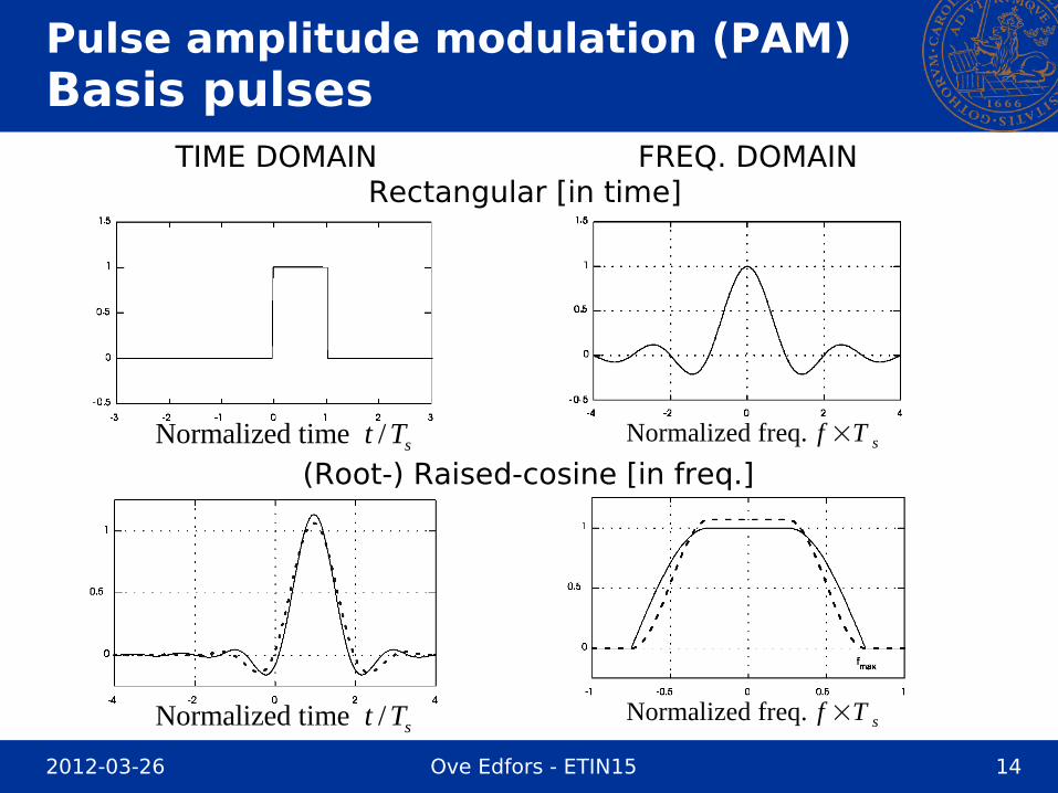
What we need are basis pulses g(t) with nice properties like:
- Narrow spectrum (low side-lobes)
- Relatively short in time (low delay)
2012-03-26 Ove Edfors - ETIN15 14
Pulse amplitude modulation (PAM)Basis pulses
Normalized time / st T
Normalized time / st T
(Root-) Raised-cosine [in freq.]
Rectangular [in time]TIME DOMAIN FREQ. DOMAIN
Normalized freq. f ×T s
Normalized freq. f ×T s

2012-03-26 Ove Edfors - ETIN15 15
Pulse amplitude modulation (PAM)Interpretation as IQ-modulator
-90o
cf
( ) ( )( )ReI LPs t s t=
( ) ( )( )ImQ LPs t s t=
( )cos 2 cf tπ
( )sin 2 cf tπ−
Radiosignal
For real valued basis functions g(t) we can view PAM as:
Pulseshapingfilters
( )g t
( )g t
Mappingmb mc
( )Re mc
( )Im mc
(Both the rectangular and the (root-) raised-cosine pulses are real valued.)
2012-03-26 Ove Edfors - ETIN15 16
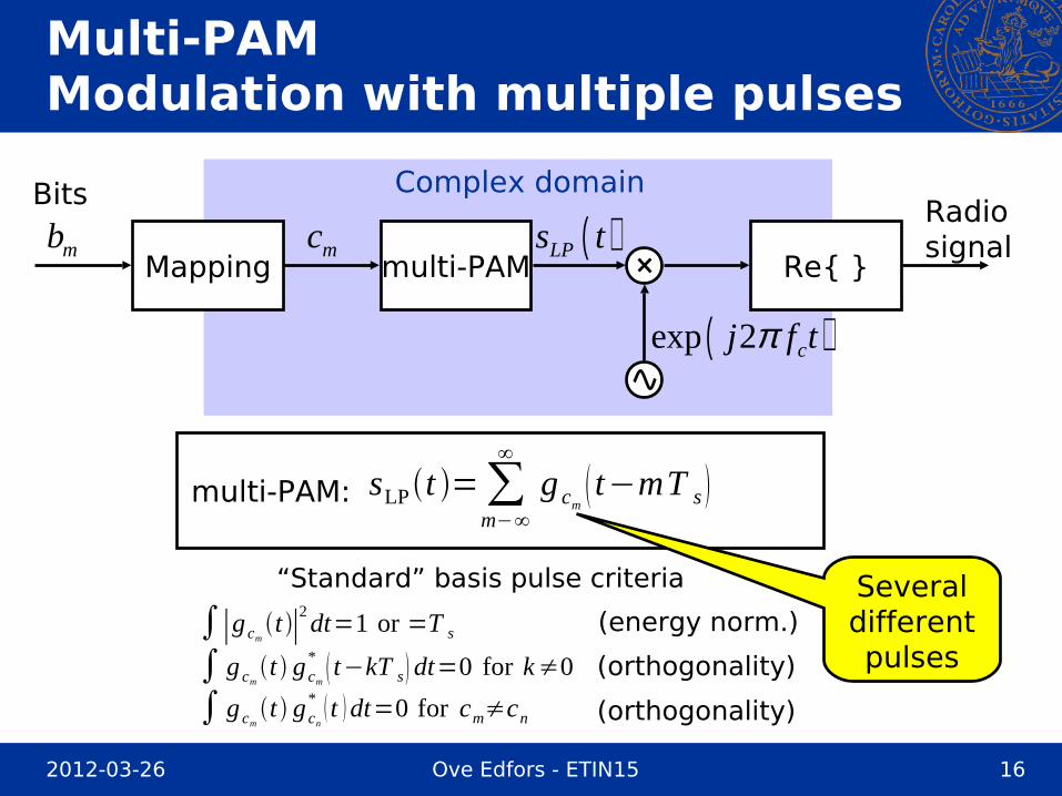
Multi-PAMModulation with multiple pulses
Complex domain
Mapping multi-PAMmb mc ( )LPs t
( )exp 2 cj f tπ
Re{ }
Radiosignal
multi-PAM:
Bits
Severaldifferentpulses
“Standard” basis pulse criteria
(energy norm.)
(orthogonality)
(orthogonality)
sLPt =∑m−∞
∞
g cm t−mT s
∫∣g cmt ∣
2dt=1 or =T s
∫ g cmt g cn
* t dt=0 for cm≠cn
∫ g cmt g cm
* t−kT s dt=0 for k≠0
2012-03-26 Ove Edfors - ETIN15 17
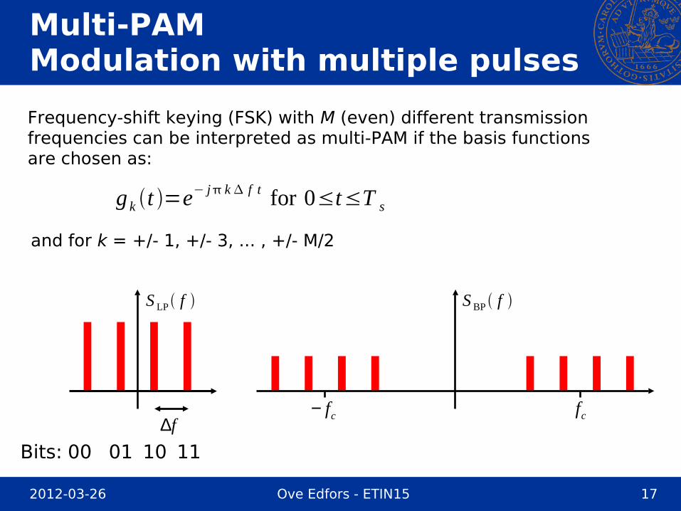
Multi-PAMModulation with multiple pulses
and for k = +/- 1, +/- 3, ... , +/- M/2
Frequency-shift keying (FSK) with M (even) different transmissionfrequencies can be interpreted as multi-PAM if the basis functionsare chosen as:
f∆cfcf−
Bits: 00 01 10 11
g k t =e− j k f t for 0≤t≤T s
S LP f S BP f
2012-03-26 Ove Edfors - ETIN15 18
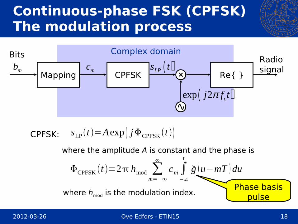
Continuous-phase FSK (CPFSK)The modulation process
Complex domain
Mapping CPFSKmb mc ( )LPs t
( )exp 2 cj f tπ
Re{ }
Radiosignal
Bits
CPFSK:
where the amplitude A is constant and the phase is
where hmod is the modulation index.Phase basis
pulse
CPFSK t =2 hmod ∑m=−∞
∞
cm∫−∞
t
g u−mT du
sLPt =Aexp jCPFSK t
2012-03-26 Ove Edfors - ETIN15 19
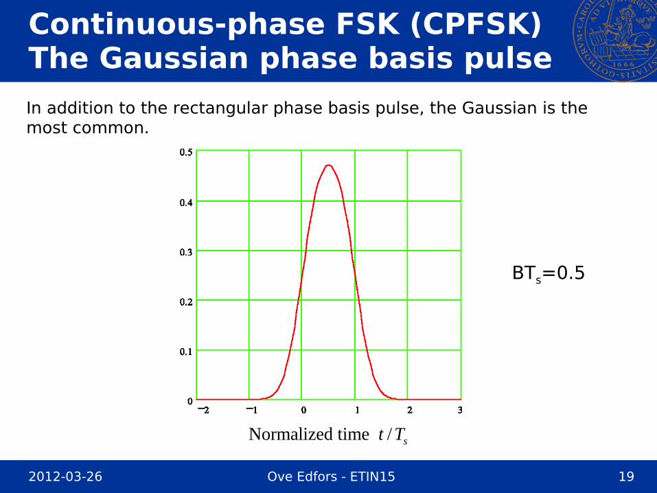
Continuous-phase FSK (CPFSK)The Gaussian phase basis pulse
Normalized time / st T
BTs=0.5
In addition to the rectangular phase basis pulse, the Gaussian is themost common.

2012-03-26 Ove Edfors - ETIN15 20
IMPORTANT MODULATIONFORMATS
2012-03-26 Ove Edfors - ETIN15 21
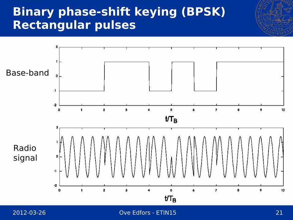
Binary phase-shift keying (BPSK)Rectangular pulses
Radiosignal
Base-band

2012-03-26 Ove Edfors - ETIN15 22
Binary phase-shift keying (BPSK)Rectangular pulses
Complex representation Signal constellation diagram

2012-03-26 Ove Edfors - ETIN15 23
Binary phase-shift keying (BPSK)Rectangular pulses
Power spectraldensity for BPSK
Normalized freq. f ×T b

2012-03-26 Ove Edfors - ETIN15 24
Binary phase-shift keying (BPSK)Raised-cosine pulses (roll-off 0.5)
Base-band
Radiosignal

2012-03-26 Ove Edfors - ETIN15 25
Binary phase-shift keying (BPSK)Raised-cosine pulses (roll-off 0.5)
Complex representation Signal constellation diagram

2012-03-26 Ove Edfors - ETIN15 26
Binary phase-shift keying (BPSK)Raised-cosine pulses (roll-off 0.5)
Power spectraldensity for BAM
Much higher spectral efficiency than BPSK (with
rectangularpulses).
Normalized freq. f ×T b

2012-03-26 Ove Edfors - ETIN15 27
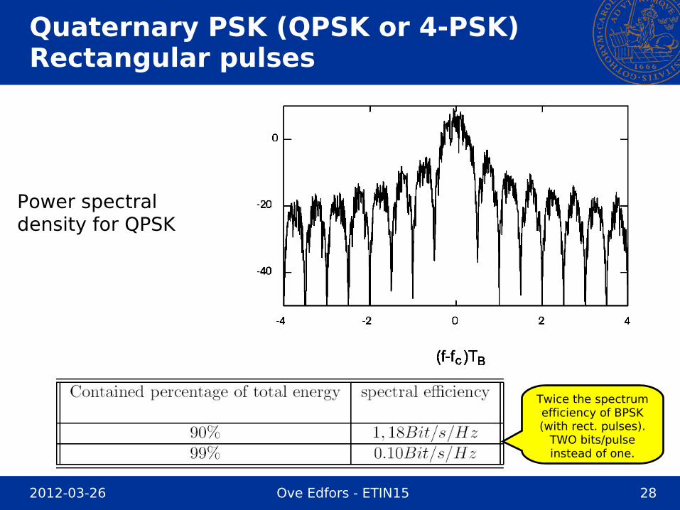
Quaternary PSK (QPSK or 4-PSK)Rectangular pulses
Complex representation
Radiosignal
2012-03-26 Ove Edfors - ETIN15 28
Quaternary PSK (QPSK or 4-PSK)Rectangular pulses
Power spectraldensity for QPSK
Twice the spectrum efficiency of BPSK (with rect. pulses).
TWO bits/pulseinstead of one.
2012-03-26 Ove Edfors - ETIN15 29
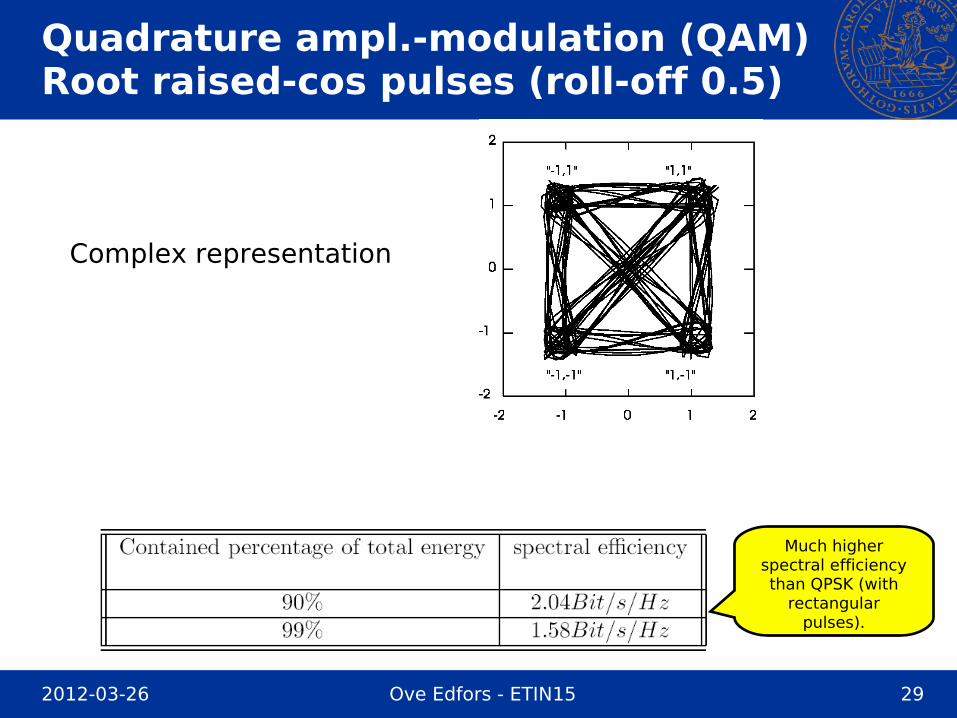
Quadrature ampl.-modulation (QAM)Root raised-cos pulses (roll-off 0.5)
Complex representation
Much higher spectral efficiency than QPSK (with
rectangularpulses).

2012-03-26 Ove Edfors - ETIN15 30
Amplitude variationsThe problem
Signals with high amplitude variations leads to less efficient amplifiers.
Complex representation of QPSK
It is a problem that the signalpasses through the origin, wherethe amplitude is ZERO.(Infinite amplitude variation.)
Can we solve this problem in a simpleway?
2012-03-26 Ove Edfors - ETIN15 31
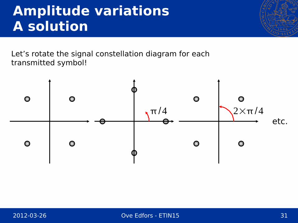
Amplitude variationsA solution
Let’s rotate the signal constellation diagram for eachtransmitted symbol!
/4 2×/4etc.

2012-03-26 Ove Edfors - ETIN15 32
Amplitude variationsA solution
Looking at the complex representation ...
QPSK without rotation QPSK with rotation
A “hole” is created in the center. No close to zero amplitudes.

2012-03-26 Ove Edfors - ETIN15 33
- Differential QPSK (DQPSK)/ 4π
Complex representation
Still uses the same rectangular pulses as QPSK - the powerspectral density and the spectral efficiency are the same.
This modulation type is used in several standards for mobilecommunications (due to it’s low amplitude variations).

2012-03-26 Ove Edfors - ETIN15 34
Offset QPSK (OQPSK)Rectangular pulses
In-phasesignal
Quadraturesignal
There is one bit-time offset between the in-pase and the quadraturepart of the signal (a delay on the Q channel). This makes the transitionsbetween pulses take place at different times!

2012-03-26 Ove Edfors - ETIN15 35
Offset QPSKRectangular pulses
Complex representation
This method also creates a hole in the
center, giving less amplitude variations.

2012-03-26 Ove Edfors - ETIN15 36
Offset QAM (OQAM)Raised-cosine pulses
Complex representation
This method also creates a hole in the center, but has larger amplitude variations
than OQPSK.

2012-03-26 Ove Edfors - ETIN15 37
Phase
32
2
12
−12
−
−32
−2
T bt
Continuous-phase modulation
Basic idea:- Keep amplitude constant- Change phase continuously
11
1 1
1
0
0 0
0
0
In this particular examplewe change the phase ina piecewise linear fashionby +/- π/2, depending onthe data transmitted.
This type of modulationcan be interpreted both as phase and frequencymodulation. It is calledMSK (minimum shift keying) orFFSK (fast frequency shift keying).
MSK/FFSK

2012-03-26 Ove Edfors - ETIN15 38
Minimum shift keying (MSK)
Simple MSK implementation
Rectangularpulsefilter
01001
0 1 0 0 1
Voltagecontrolledoscillator
(VCO)
MSK signal
2012-03-26 Ove Edfors - ETIN15 39
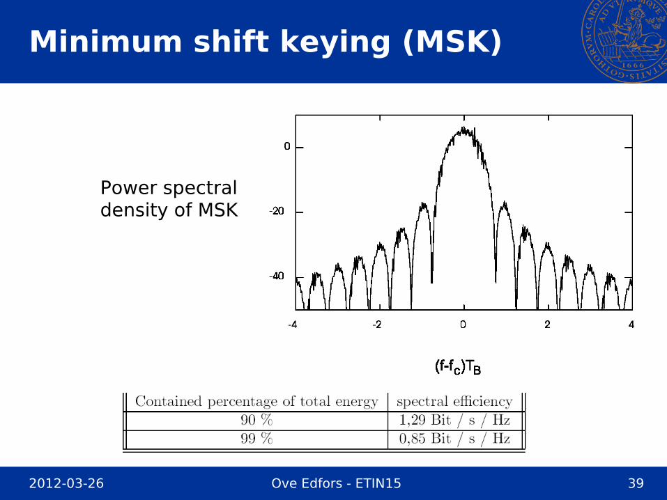
Minimum shift keying (MSK)
Power spectraldensity of MSK

2012-03-26 Ove Edfors - ETIN15 40
Gaussian filtered MSK (GMSK)
Further improvement of the phase: Remove ’corners’
MSK(Rectangular pulse filter)
Gaussian filtered MSK - GMSK(Gaussian pulse filter)
(Simplified figure)Phase
32
2
12
−12
−
−32
−2
T bt
1 1 1
1 1
1
0 0
0
1 1 1
1 1
1
0 0
0
Phase
32
2
12
−12
−
−32
−2
T bt

2012-03-26 Ove Edfors - ETIN15 41
Gaussian filtered MSK (GMSK)
Simple GMSK implementation
Gaussianpulsefilter
01001
0 1 0 0 1
Voltagecontrolledoscillator
(VCO)
GMSK signal
When implemented this “simple” way, it is usually called Gaussianfiltered frequency shift keying (GFSK).
GSFK is used in e.g. Bluetooth.

2012-03-26 Ove Edfors - ETIN15 42
Gaussian filtered MSK (GMSK)
Digital GMSK implementation
-90o
cf
( )cos 2 cf tπ
( )sin 2 cf tπ−
D/A
D/A
Digitalbaseband
GMSKmodulator
Data
AnalogDigital
This is a more precise implementation of GMSK, which is used ine.g. GSM.

2012-03-26 Ove Edfors - ETIN15 43
Gaussian filtered MSK (GMSK)
Power spectraldensity of GMSK.
BT = 0.5 here(0.3 in GSM)

2012-03-26 Ove Edfors - ETIN15 44
How do we use all these spectral efficiencies?
Example: Assume that we want to use MSK to transmit 50 kbit/sec,and want to know the required transmission bandwidth.
Take a look at the spectral efficiency table:
The 90% and 99% bandwidths become:
90% 50000 /1.29 38.8 kHzB = =
99% 50000 / 0.85 58.8 kHzB = =

2012-03-26 Ove Edfors - ETIN15 45
Summary
TABLE 11.1 in textbook.
BPSK withroot-raised
cosinepulses


![RADIO SYSTEMS - ETIN15 Lecture no: 12 · PDF fileRADIO SYSTEMS - ETIN15 Lecture no: 12 Wireless LANs/data ... Some WLANs OFDM Data rate [Mbit/sec] Year 1 10 100 0.1 ... Has some similarities](https://img.pdfslide.us/doc/110x75/5aab31aa7f8b9aa9488bb17c/radio-systems-etin15-lecture-no-12-systems-etin15-lecture-no-12-wireless-lansdata.jpg)