Embed Size (px)
Citation preview

Advances in Radio Science, 3, 111–117, 2005SRef-ID: 1684-9973/ars/2005-3-111© Copernicus GmbH 2005
Advances inRadio Science
New Standards for the Validation of EMC Test Sites particularlyabove 1 GHz
S. Battermann1, F. W. Trautnitz 2, and H. Garbe1
1Institut fur Grundlagen der Elektrotechnik und Messtechnik, University of Hannover, Appelstrasse 9A, 30167 Hannover,Germany2Albatross Projects GmbH, Daimlerstraße 17, 89564 Nattheim, Germany
Abstract. Standards for the validation of alternative test siteswith conducting groundplane exist for the frequency range30–1000 MHz since the end of the eighties. Recently theprocedure for fully anechoic rooms (FAR) has been includedin CISPR 16 after more than 10 years intensive discussionin standards committees (CENELEC, 2002; CISPR, 2004).But there are no standards available for the validation of al-ternative test sites above 1 GHz. The responsible workinggroup (WG1) in CISPR/A has drawn up the 7th commondraft (CD). A CDV will be published in spring 2005. TheGerman standards committee VDE AK 767.4.1 participatesin the drafting of the standard. All suggested measurementprocedures proposed in the last CDs have been investigatedby measurements and theoretical analysis. This contributiondescribes the basic ideas and problems of the validation pro-cedure of the test site. Furthermore measurement results andnumerical calculations will be presented especially for theuse of omni-directional antennas.
1 Introduction
1.1 FAR ideal and real - differences
In the ideal case the FAR has no reflections and measure-ments can be performed under free-space conditions withouta ground plane. But in real case a lot of components haveto be integrated in the fully anechoic room such as turntable,double floor, masts, cameras, lightning, airing openings, ca-bling. And last but not least the used absorbers in the roomhave to satisfy the relevant standards with low reflectivity forthe entire frequency range and all incident angles (Hollowayet al., 1997).
As can be seen in Fig. 1 the resulting field at the receivingantenna (2) is a superposition of the desired signal from thedirect pathsdirect and unwanted reflected signals likesref l.1andsref l.2. In addition to Fig. 1 one has to take into account
Correspondence to:S. Battermann([email protected])
the 3-D case with reflections from all 6 walls. These reflec-tions cause an interference pattern at the receiving antennathat influences the measurements. Therefore possible reflec-tions have to be measured and quantified during the valida-tion procedure.
1.2 Radiation pattern of an equipment under test
Figure 2 shows the radiation pattern of a simple two-slot ra-diator at 5 GHz fed with a phase shift (two magnetic dipoles)as exemplary equipment under test (EUT). Significant sidelobes are visible which may cause reflections at the chamberwalls. Generally most EUTs in the frequency range above1 GHz have to be dealt as a “large EUT” with their dimen-sions comparable with the wavelength. This results in a verycomplex radiation pattern. The validation procedure has totake into account these possible patterns.
It is a consequence that an isotropic source would be thebest source to illuminate the whole room and to find all un-wanted reflections during the validation procedure. Unfortu-nately it is a problem to realize this kind of electromagneticsource.
1.3 Typically used validation methods
The site qualification in the frequency range from30–1000 MHz is done by measuring the Normalized Site At-tenuation (NSA) in the EUT volume according to the “vol-ume method”. Contrary to the NSA measurement CISPR/Aproposed a different procedure for the site qualification above1 GHz. Similar to the free space VSWR measurement (IEEE,1979) the so-called “Site-VSWR” is to be measured (Appel-Hansen, 1973). During discussion in standards committeesover the last years, the main problem was the missing omni-directional antenna.
1.3.1 Validation with directional antennas
The first validations have been carried out with high direc-tional antennas (e.g. logarithmic-periodic or horn antennas).A double-ridged horn antenna covers the frequency range

112 S. Battermann et al.: Standards for Validation of EMC Test Sites particularly above 1 GHz
hFloor
sdirect
s refl.1
Antenna 1 Antenna 2
Double Floor
hCeiling
Measurement Distance
Lamp (worst case mounting)
Ceiling Absorbers
Ground Absorbers
s refl.2
Wal
l Abs
orbe
rsFig. 1. Superposition of direct and reflected signal.
CONCEPT DATA: Slot Antenna
X
Y
Z
Far field, max. magnitude
gain: 5.3466direct.: 4.8619PHI start: 0.0PHI end: 360.THETA start: 0.0THETA end: 180Frequency: 5000.0000 MHz
Fig. 2. Radiation pattern of a slot radiator.
from 1–18 GHz, therefore an antenna change can be avoided.But due to the small 3 dB beam-width of the horn the roomcharacteristics cannot be observed when the antennas arefaced to each other. The magnitude of reflected signals bythe walls can nearly be neglected (Fig. 3). Therefore thismethod is inappropriate for room validation, because it willnot test the room characteristics.
In a different interesting approach one antenna is fixed andthe other antenna will be rotated from 90◦ to 270◦ to detectreflections from different angles of the back wall (Windlerand Camell, 2003). In this case the low front to back ratioof horn antennas for the low frequency range is a problem.Thus it is impossible to separate the reflection by the back-side wall and the back lobe of the antenna, which results in alow reproducibility. This is the reason why this method wasno longer under consideration.
1.3.2 Validation with omni-directional antennas
Monopole antennas (Fig. 4 right) show a strong frequencydependent radiation pattern. Figures 5 and 6 show the verti-cal radiation pattern of a conical monopole antenna (discone)
3 dB Half-Power Beamwidth
Fig. 3. Insufficient validation with directional antennas.
Balun
Fig. 4. Biconical and monopole antennas (not to scale).
for 3 and 8 GHz. These frequency dependent characteris-tics are well known in literature (Kraus, 1950; Schelkunoff,1952).
These frequency dependent radiation patterns cannot gen-erate a homogenous illumination of the whole room. Ob-jects below the antenna ground plane will be hardly illumi-nated. To validate the whole room it is necessary to per-form at least two measurements in each polarization plane(antenna up/down and left/right). Thus four measurementshave to be performed. Nevertheless the illumination is veryinhomogeneous. The cable routing by itself is a real problemin this case. A solution would be the use of smaller conesand especially smaller metallic counterpoises for higher fre-quencies. But this is not practicable.
However biconical antennas exist, which provide an ex-cellent dipole type antenna pattern in the frequency range upto 3 GHz. Excited by this, a German company developeda small biconical antenna with a dipole type pattern for 3–18 GHz. The 3 dB beam-width decreases with increasingfrequency. This is visible in the radiation pattern in Fig. 7,which is based on a numerical simulation of the biconicalantenna. But the antenna still provides a dipole radiationpattern. Therefore it is possible to perform the site valida-tion with only two measurements (vertical and horizontal).In contrast to the monopole antenna a better illumination ofthe room is possible.

S. Battermann et al.: Standards for Validation of EMC Test Sites particularly above 1 GHz 113
0
-5
-10
-15
-20
-25
-30 0
30
60
90
120
150
180
210
240
270
300
330
Radiation Pattern, E-plane, vert. 3000 MHz
Fig. 5. Radiation pattern Monopole 3 GHz.
0
-5
-10
-15
-20
-25
-30 0
30
60
90
120
150
180
210
240
270
300
330
Radiation Pattern, E-plane, vert. 8000 MHz
Fig. 6. Radiation pattern Monopole 8 GHz.
2 Validation procedure
2.1 Basic idea
Several kinds of validations have been discussed in the dif-ferent CDs (CISPR, 2004). The site validation method tests aspecified cylindrical test volume, typically located above thecenter of the turntable, for the combination of site, receiveantenna and absorbing material placed on the ground plane(if needed to meet the criterion). The test volume has to en-close the EUT including cabling. The Site-VSWR methodmeasures the standing wave along a line in the room – causedby unwanted reflections and resulting interferences. This iscomparable to the one-dimensional standing wave on a trans-mission line, which occurs if the line is not terminated withits characteristic impedance. The VSWR is calculated fromthe maximum and minimum voltage of the standing wave onthe line. The Site-VSWR method uses the measured max-imum and minimum electric field strength. It is necessaryto keep in mind, that in reality a three dimensional standing
0
-5
-10
-15
-20
-25
-30 0
30
60
90
120
150
180
210
240
270
300
330
Radiation Pattern, E-plane, vert. 3 / 8 GHz
3 GHz8 GHz
Fig. 7. Radiation pattern of biconical antenna at 3 GHz and 8 GHz.
wave exists in the room but the Site-VSWR method measuresonly a small part of it.
The transmit antenna (biconical antenna) is located atspecified positions in the test volume (see Fig. 8). Thereceive antenna for the validation has to be the same an-tenna, which will be used for measurements later on. Dueto the larger beam-width a stacked log.-per.-antenna is rec-ommended.
Furthermore the reciprocal method is possible by movinga field probe in the test volume as receive antenna. In thiscase the normal receive antenna for EUT measurements isthe transmitting antenna. It is allowed to change the trans-mitting and receiving antenna, because the system is passiveand linear (reciprocity theorem).
For each frequency the maxima and minima of all mea-sured voltages at the defined positions have to be determinedand the Site-VSWR will be calculated with the followingequation:
sV SWR = max{Vmeas.[dB]} − min {Vmeas.[dB]} (1)
In a free-space test environment, the Site-VSWR is di-rectly related to the influence of undesired reflections (Appel-Hansen, 1973). The FAR or semi-anechoic chamber (SAC)fulfils the standard if thesV SWR is below a limit of about3.5 dB. This site acceptance criterion was developed by con-sidering the desired magnitude of site effects, combined withinfluence quantities due to the instrumentation and proce-dures used to perform the site validation. Table 1 lists theparameters and their values used to establish the 3.5 dB cri-terion.
2.2 New Draft (CD December 2004)
In the new Draft (December 2004) the arrangement of mea-surement positions has been changed. As depicted in Figs. 8and 9 at each position six measurements have to be done atnon-equidistant positions. For the front position the distances1s relative to position F6 are 2 cm, 10 cm, 18 cm, 30 cm and

114 S. Battermann et al.: Standards for Validation of EMC Test Sites particularly above 1 GHz
Table 1. Uncertainty budget of the site-VSWR validation method and resulting acceptance criteria.
Influence Probability Distribution Value (k=1)/dB
Site Imperfections (Target) Normal ±1.0Repeatability ofsV SWR validation method Normal ±1.0Source Non-Ideal Characteristics Rectangular ±1.0(Pattern Deviations, Balance, Cross Polarization)
Standard uncertainty Sum of influence Quantities ±1.65(RSS combined)=[12+12+(1.5/1.73)2]0.5
Expanded uncertaintyk=2 sV SWR tolerance value sV SWR≤3.5=V maxdB−V mindB
Receiving antenna(BiLog)
Ceiling Absorbers
h
Test
Vol
ume
1
h2
ha
Floor Absorbers
Fig. 8. Vertical section of the validated volume.
F1 to F6
L1 to L6
α
R1 to R6
α
d
Reference point
C1 to C6
Fig. 9. Horizontal section ath1 of the validated volume.
40 cm. The front positions in heighth1 andh2 are manda-tory. For floor standing equipment that cannot be raised, aheightha of 30 cm may be obstructed by absorbers placedon the ground of the SAC. The other positions depend on thereceive antenna half power beam-width, absorber placement(for SAC) and dimensions of the test volume. The necessarypoints are defined in a given flow-chart in the standard.
0.1 x 0.1 m metallic plate
(defined reflector)
0.6 x 0.6 m plane with calculated field-strength
MonopoleAntenna
BiconicalAntenna
Measurement Distance 1 m
x
yz
or
Fig. 10. Schematic of the Model.
3 Calculations and measurements
3.1 Description of the model
A numerical model has been developed to get a better in-sight into the transmit antenna pattern influence. It consistsof only one antenna (monopole or biconical) placed at theorigin (Fig. 10). The program CONCEPT has been usedfor the calculations, which is based on the Method of Mo-ments. The antenna is fed with 1 V at 50 Ohms. The fieldhas been calculated in the y-z-plane with the center position(1 m, 0 m, 0 m) and the dimension (60×60 cm). The metal-lic reflector is 10×10 cm and it is located in the z-x-plane at(0.5 m, 1 m, 0 m). The center position of the plate is movedin z-direction only.
At each frequency a different interference pattern existsand the calculations have been carried out exemplarily for thefrequency of 9 GHz. Thus it is possible to visualize the fieldpattern for the monopole and biconical antenna for specialpositions of the reflector. During the validation procedure(Site-VSWR) the interference pattern would be validated forall frequencies.
S. Battermann et al.: Standards for Validation of EMC Test Sites particularly above 1 GHz 115
-0.2 0 0.2
-0.2
-0.1
0
0.1
0.2
0.3z-
Pos
.
Ez / V/m (without reflector)
0.27
0.28
0.29
0.3
0.31
-0.2 0 0.2
-0.2
-0.1
0
0.1
0.2
0.3
z-P
os.
Ez/ V/m (with reflector z=0m)
0.25
0.3
0.35
-0.2 0 0.2
-0.2
-0.1
0
0.1
0.2
0.3
y-Pos.
z-P
os.
∆Ez/ V/m (Difference z=0m)
-0.05
0
0.05
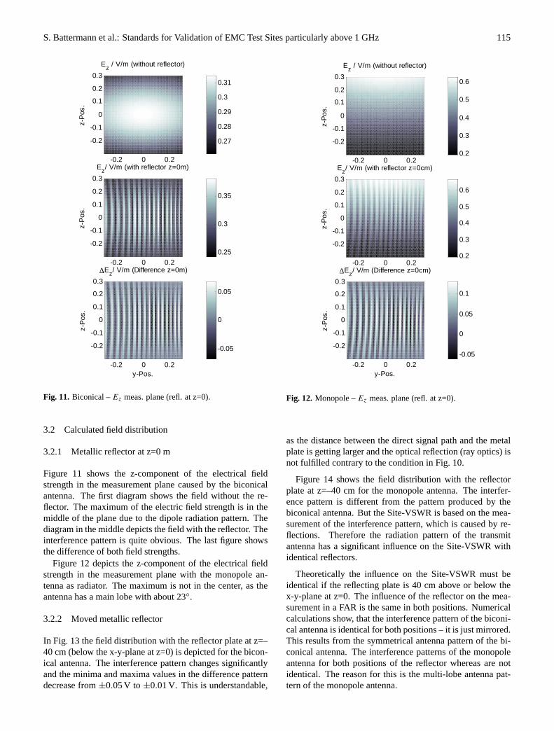
Fig. 11. Biconical –Ez meas. plane (refl. at z=0).
3.2 Calculated field distribution
3.2.1 Metallic reflector at z=0 m
Figure 11 shows the z-component of the electrical fieldstrength in the measurement plane caused by the biconicalantenna. The first diagram shows the field without the re-flector. The maximum of the electric field strength is in themiddle of the plane due to the dipole radiation pattern. Thediagram in the middle depicts the field with the reflector. Theinterference pattern is quite obvious. The last figure showsthe difference of both field strengths.
Figure 12 depicts the z-component of the electrical fieldstrength in the measurement plane with the monopole an-tenna as radiator. The maximum is not in the center, as theantenna has a main lobe with about 23◦.
3.2.2 Moved metallic reflector
In Fig. 13 the field distribution with the reflector plate at z=–40 cm (below the x-y-plane at z=0) is depicted for the bicon-ical antenna. The interference pattern changes significantlyand the minima and maxima values in the difference patterndecrease from±0.05 V to ±0.01 V. This is understandable,
-0.2 0 0.2
-0.2
-0.1
0
0.1
0.2
0.3
z-P
os.
Ez / V/m (without reflector)
0.2
0.3
0.4
0.5
0.6
-0.2 0 0.2
-0.2
-0.1
0
0.1
0.2
0.3
z-P
os.
Ez/ V/m (with reflector z=0cm)
0.2
0.3
0.4
0.5
0.6
-0.2 0 0.2
-0.2
-0.1
0
0.1
0.2
0.3
y-Pos.
z-P
os.
∆Ez/ V/m (Difference z=0cm)
-0.05
0
0.05
0.1
Fig. 12. Monopole –Ez meas. plane (refl. at z=0).
as the distance between the direct signal path and the metalplate is getting larger and the optical reflection (ray optics) isnot fulfilled contrary to the condition in Fig. 10.
Figure 14 shows the field distribution with the reflectorplate at z=–40 cm for the monopole antenna. The interfer-ence pattern is different from the pattern produced by thebiconical antenna. But the Site-VSWR is based on the mea-surement of the interference pattern, which is caused by re-flections. Therefore the radiation pattern of the transmitantenna has a significant influence on the Site-VSWR withidentical reflectors.
Theoretically the influence on the Site-VSWR must beidentical if the reflecting plate is 40 cm above or below thex-y-plane at z=0. The influence of the reflector on the mea-surement in a FAR is the same in both positions. Numericalcalculations show, that the interference pattern of the biconi-cal antenna is identical for both positions – it is just mirrored.This results from the symmetrical antenna pattern of the bi-conical antenna. The interference patterns of the monopoleantenna for both positions of the reflector whereas are notidentical. The reason for this is the multi-lobe antenna pat-tern of the monopole antenna.

116 S. Battermann et al.: Standards for Validation of EMC Test Sites particularly above 1 GHz
-0.2 -0.1 0 0.1 0.2
-0.2
-0.1
0
0.1
0.2
0.3
z-P
os.
Ez/ V/m (with reflector z=-40cm)
0.26
0.27
0.28
0.29
0.3
0.31
-0.2 -0.1 0 0.1 0.2
-0.2
-0.1
0
0.1
0.2
0.3
y-Pos.
z-P
os.
∆Ez/ V/m (Difference z=-40cm)
-0.01
-0.005
0
0.005
0.01
Fig. 13. Bicon. –Ez meas. plane (refl. at z=-40 cm).
3.2.3 Receiving antenna influence
The numerical calculations are independent of the receive an-tenna. But the validation procedure has to be carried out withthe receive antenna which will be also used for the measure-ments. Further measurements showed that a high directionalreceiving antenna neglects reflections, as the 3 dB beam-width is too small. The smaller the beam width - the lowerthe Site-VSWR. That is why the receive antenna characteris-tics have to be defined for the validation procedure. Furtherproblems with antennas above 1 GHz, which have to be con-sidered, are elucidated in (Windler and Camell, 2001).
3.3 Measurements of the Site-VSWR
The following diagrams show measurements of the Site-VSWR in a 3 m FAR with both antennas. The above-depicted effects with the frequency dependent radiation pat-tern are quite obvious with the monopole antenna in Fig. 15(right). The monopole overestimates directions at special fre-quencies, due to its radiation characteristics.
4 Conclusion
The measurements show, that the Site-VSWR method is suit-able for FAR validation above 1 GHz. Nevertheless everytest site has a certain inaccuracy. These values of the inac-curacy are taken into consideration and also defined in the
-0.2 -0.1 0 0.1 0.2
-0.2
-0.1
0
0.1
0.2
0.3
z-P
os.
Ez/ V/m (with reflector z=-40cm)
0.3
0.4
0.5
0.6
-0.2 -0.1 0 0.1 0.2
-0.2
-0.1
0
0.1
0.2
0.3
y-Pos.z-
Pos
.
∆Ez/ V/m (Difference z=-40cm)
0.02
0.025
0.03
0.035
0.04
Fig. 14. Monop. –Ez meas. plane (refl. at z=-40cm).
coming standard. To obtain comparable results between dif-ferent FARs the transmit and receive antenna characteristicshave to be taken into account during the validation. Withoutconsidering the antenna pattern it would be possible to useantennas with high directivity and the FAR will pass duringthe validation. But during measurements there will be prob-lems due to possible reflections caused by the radiation pat-tern of the EUT. Therefore the standardization is concernedin defining the necessary antenna pattern especially for thetransmit antenna.
The transmit antenna needs a dipole type radiation pattern.With vertical and horizontal polarization it is possible to illu-minate the whole room. The monopole antenna with its fre-quency dependent multi-lobe radiation pattern is not suitedfor the site validation. The biconical antenna seems to besuited, due to its dipole type radiation pattern and broadbandcharacteristics.
References
Appel-Hansen, J.: Reflectivity Level of Radio Anechoic Chambers,IEEE Trans. Antennas and Propagation, Vol. AP-21, No. 4, 490–498, July 1973.
CENELEC Report R210-010: Electromagnetic Compatibility–Emission measurements in Fully Anechoic Chambers, EuropeanCommittee for Electrotechnical Standardization, Brussels, June2002.
CISPR A/531/CD: Site Evaluation above 1 GHz, Committee Inter-national Special des Perturbation Radioelectrique, 2004.

S. Battermann et al.: Standards for Validation of EMC Test Sites particularly above 1 GHz 117
0 0.5 1 1.5 2
x 104
0
1
2
3
4
5
6
7
8
9
10Biconical antenna Site-VSWR
f / MHz
Site
-VS
WR
/ dB
0 0.5 1 1.5 2
x 104
0
1
2
3
4
5
6
7
8
9
10Monopole
f / MHz
Site
-VS
WR
/ dB
Fig. 15. Site-VSWR with biconical antenna and with monopole antenna.
DIN EN 50147-2:1996-07: Anechoic chambers – Part 2: Alterna-tive test site suitability with respect to site attenuation, 1996.
Holloway, C., DeLyser, R , German, R., McKenna, P., and Kanda,M.: Comparison of Electromagnetic Absorber Used in Anechoicand Semi-Anechoic Chamber for Emission and Immunity Test-ing of Digital Devices, IEEE Trans. EMC, Vol. 39, No. 1, 33–47,Feb. 1997.
IEEE Standard Test Procedures for Antennas, ANSI/IEEE Std 149-1979.
Kraus, J. D.: Antennas, McGraw-Hill, 1950.Schelkunoff, S. A.: Advanced Antenna Theory, New York: Wiley,
1952.Windler, M. J. and Camell, D.: Research on site qualification above
1 GHz, Proc. 15th Int. Zurich Symp. on electromagnetic Com-patibility, Switzerland, 333–336, Feb. 18-20, 2003.
Windler, M. J. and Camell, D.: Measuring Antennas above 1 GHz,Proc. 14th International Zurich Symp. on Electromagnetic Com-patibility (Supplement), Switzerland, 91–95, 2001.