Embed Size (px)
Citation preview
RESEARCH Open Access
Validation of new transmission detectortransmission factors for online dosimetry:an experimental studySo-Yeon Park1,2, Jong Min Park2,3,4, Jung-in Kim2,3,4, Sungyoung Lee4 and Chang Heon Choi2,3,4*
Abstract
Background: The demand for dose verification during treatment has risen with the increasing use of intensity-modulated radiation therapy (IMRT) and volumetric modulated arc therapy (VMAT) in modern radiation therapy.This study aims to validate the transmission factors of a new transmission detector, the Dolphin online monitoringsystem (IBA Dosimetry, Schwarzenbruck, Germany), for clinical use.
Methods: The transmission factors of the Dolphin detector were evaluated using 6 MV, 6 flattening filter free (FFF),10 MV, and 10 FFF clinical beams from a TrueBeam STx linear accelerator system. Two-dimensional (2D) dosedistributions were measured through portal dosimetry with and without Dolphin to derive the transmissionfactors. The measurements were performed using 10 IMRT and 10 VMAT treatment plans. The transmissionfactors were calculated using a non-negative least squares problem solver for the 2D dose matrix. Normalizedplans were generated using the derived transmission factors. Patient-specific quality assurance with normalizedplans was performed using portal dosimetry and an ArcCheck detector to verify the transmission factors. Thegamma passing rates were calculated for the 2%/2 mm and 1%/1 mm criteria.
Results: The transmission factors for the 6 MV, 6 FFF, 10 MV, and 10 FFF beams, were 0.878, 0.824, 0.913, and0.883, respectively. The average dose difference between the original plan without Dolphin and the normalized plan withDolphin was less than 1.8% for all measurements. The mean passing rates of the gamma evaluation were 98.1 ± 2.1 and82.9 ± 12.6 for the 2%/2 mm and 1%/1 mm criteria, respectively, for portal dosimetry of the original plan. In the case ofthe portal dosimetry of the normalized plan, the mean passing rates of the gamma evaluation were 97.2 ± 2.8 and 79.1 ±14.8 for the 2%/2 mm and 1%/1 mm criteria, respectively.
Conclusions: The Dolphin detector can be used for online dosimetry when valid transmission factors are applied to theclinical plan.
Keywords: Transmission detector, Transmission factors, Portal dosimetry, Online dosimetry
BackgroundIn modern radiation therapy, intensity-modulated radi-ation therapy (IMRT), volumetric modulated arc therapy(VMAT), and stereotactic ablative radiotherapy (SABR)are used for precise radiation delivery [1, 2]. These tech-niques can generate a sophisticated dose distribution,delivering high doses to the target with lower doses to
critical organs. Such dose distributions are delivered using abeam sequence with various degrees of freedom to addressan increasingly conformal dose distribution [3]. Therefore,they require a comprehensive quality assurance (QA) testingto verify the dose delivery [4–6]. These QA methods candetect possible errors, which can cause serious side effectsfor patients [7, 8]. Hence, pretreatment patient-specificdosimetry is essential [9].In recent decades, IMRT verification techniques have
been developed to increase the efficiency and accuracyof associated QA procedures [10]. Plan verification isgenerally performed using detector array systems, ion
* Correspondence: [email protected] of Radiation Medicine, Seoul National University Medical ResearchCenter, Seoul, Republic of Korea3Department of Radiation Oncology, Seoul National University Hospital,Seoul, Republic of KoreaFull list of author information is available at the end of the article
© The Author(s). 2018 Open Access This article is distributed under the terms of the Creative Commons Attribution 4.0International License (http://creativecommons.org/licenses/by/4.0/), which permits unrestricted use, distribution, andreproduction in any medium, provided you give appropriate credit to the original author(s) and the source, provide a link tothe Creative Commons license, and indicate if changes were made. The Creative Commons Public Domain Dedication waiver(http://creativecommons.org/publicdomain/zero/1.0/) applies to the data made available in this article, unless otherwise stated.
Park et al. Radiation Oncology (2018) 13:156 https://doi.org/10.1186/s13014-018-1106-y
chamber, or film before first treatment. However, suchpretreatment plan verifications have certain limitations[11, 12]. Verification is performed only once without thepatient and before the first fraction on the assumptionthat the dose is delivered with no change or error overthe course of treatment. However, this approach does notensure that the planned dose is delivered to the patientduring all treatment fractions because the mechanicalconditions of the treatment machine can vary.In modern radiotherapy, the focus has shifted toward
adaptive radiotherapy, and an increasing demand for onlinedose verification of dose delivery has been observed [13].Dose-distribution prediction by analyzing the machine deliv-ery log file has been introduced for online dose verification[14]. Reconstructed three-dimensional (3D) dose verificationmodels have also been developed for the same purpose[15–17]. In other ways, the 3D dose has been reconstructedfrom a computed tomography (CT) dataset based on meas-urement data and 3D dose calculation software [18].Accordingly, transmission detectors have been devel-
oped to address these demands, and several commercialproducts are now available for clinical purposes (e.g., IQM(iRT Systems GmbH, Koblenz, Germany), OCTAVIUS IIIDAVID (PTW Freiburg GmbH, Freiburg, Germany),Delta4 Discover (ScandiDos AB, Uppsala, Sweden), andthe Dolphin online monitoring system (IBA Dosimetry,Schwarzenbruck, Germany) [11, 19, 20].Dolphin is a monitoring system with transmission detec-
tors. The measurement data can be reconstructed to a 3Ddose distribution on a 3D-CT image set using COMPASSsoftware (IBA Dosimetry, Schwarzenbruck, Germany)[21, 22]. Dolphin can be used for pretreatment QA as wellas during each fraction. However, Dolphin has some short-comings, such as beam hardening scatter and electron con-tamination [11]. Dolphin has a technical potential functionfor online dosimetry, which can be performed by mountinga detector on the gantry during treatment [15]; however, itis not allowed for Dolphin. Note that in treatment planning,the dose is calculated without considering the attenuationby the detector. The transmission detector is locatedbetween the beam source and the patient [12], and the radi-ation beam is perturbed by the material and thickness ofthe transmission detector [23]. Until now, the treatmentplanning system (TPS) cannot address the beam attenu-ation factor of the transmission detector when a trans-mission detector is installed for online dosimetry. Inother words, TPS does not support plan optimizationand dose calculation for Dolphin. Therefore, the use ofDolphin in actual treatments is restricted [9].Cheung et al. recently presented the square field
transmission factors for 6 MV, 6 flattening filter free(FFF), 10 MV, and 10 FFF clinical beams. These factorswere previously available only for the static field usedin 3D conformal radiotherapy. However, online dosimetry
is more important for IMRT and VMAT [11]. Thedosimetric leaf gap (DLG) and the multileaf collimator(MLC) transmission are important parameters for theoptimization and dose calculation of intensity-modulatedfields delivered by the MLC [24].This study derived transmission factors of the Dolphin
online monitoring system for IMRT and VMAT planusing 6 MV, 6 FFF, 10 MV, and 10 FFF clinical beams.We generated a normalized plan, which was normalizedby transmission factors. To verify the transmission factors,the gamma index of the normalized plan was evaluatedusing two independent QA devices. In addition, the DLGand MLC transmission factors were individually measuredto confirm the change of their characteristics by theDolphin system for each available energy.
MethodsTransmission detectorThe Dolphin transmission detector was a 2D array with1513 plane-parallel ionization chambers. The volume ofeach chamber was 0.016 cm3 (diameter: 3.2 mm, height:2 mm). The chambers were arranged with a 5 mm spacingin the central area (i.e., within the inner 15 × 15 cm2 region)and with a 10 mm spacing in the outer detector area (i.e.,corresponding size in the isocenter plane: chamberdiameter: 4.89 mm, 7.63 mm, and 15.26 mm spacing inthe central and outer area, respectively).The physical size of the detector was 24.3 × 24.3 cm2. A
field size of up to 40 × 40 cm2 can be measured by installingthe interface mount on the gantry head (at 65.5 cm fromthe source for TrueBeam STx system (Ver. 2.5, VarianMedical Systems, Inc., Palo Alto, CA)). The device incorpo-rates a copper buildup plate with 1.5 mm thickness [11].
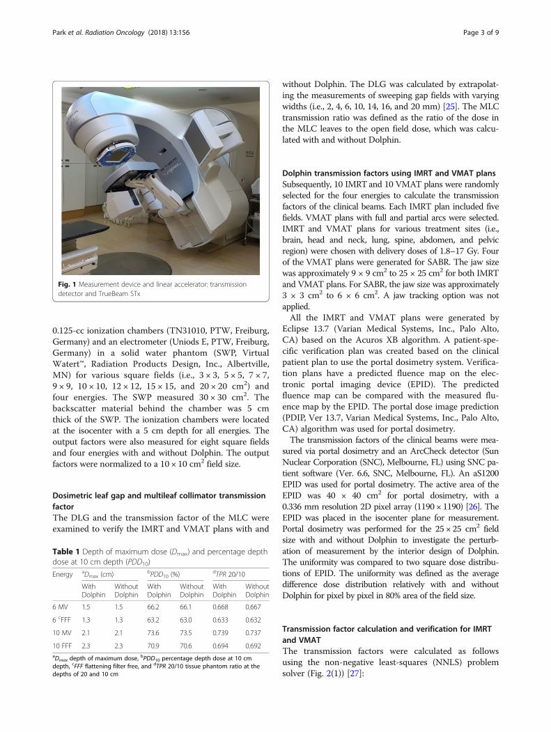
Measurement setup and energiesFigure 1 shows the basic measurement setup involving theDolphin detector and a linear accelerator. All measure-ments were conducted using the TrueBeam STx systemequipped with a high-definition 120-leaf multileaf collima-tor. The four energies (i.e., 6 MV, 6 FFF, 10 MV, and 10FFF) were used for the transmission factor measurement.The COMPASS software was not commissioned for 15MV; therefore, 15 MV was excluded from the transmis-sion factor measurement. Table 1 lists the values of thedepth of maximum dose (Dmax), the percentage depthdose at 10 cm depth (PDD10), and tissue phantomratio at the depths of 20 and 10 cm (TPR 20/10) withand with Dolphin for the four examined energies.
Transmission factor and output factor measurements forsquare fieldsThe transmission factors of regular square fields weremeasured to evaluate the field size dependency. Thetransmission factor measurement was performed with
Park et al. Radiation Oncology (2018) 13:156 Page 2 of 9
0.125-cc ionization chambers (TN31010, PTW, Freiburg,Germany) and an electrometer (Uniods E, PTW, Freiburg,Germany) in a solid water phantom (SWP, VirtualWatert™, Radiation Products Design, Inc., Albertville,MN) for various square fields (i.e., 3 × 3, 5 × 5, 7 × 7,9 × 9, 10 × 10, 12 × 12, 15 × 15, and 20 × 20 cm2) andfour energies. The SWP measured 30 × 30 cm2. Thebackscatter material behind the chamber was 5 cmthick of the SWP. The ionization chambers were locatedat the isocenter with a 5 cm depth for all energies. Theoutput factors were also measured for eight square fieldsand four energies with and without Dolphin. The outputfactors were normalized to a 10 × 10 cm2 field size.
Dosimetric leaf gap and multileaf collimator transmissionfactorThe DLG and the transmission factor of the MLC wereexamined to verify the IMRT and VMAT plans with and
without Dolphin. The DLG was calculated by extrapolat-ing the measurements of sweeping gap fields with varyingwidths (i.e., 2, 4, 6, 10, 14, 16, and 20 mm) [25]. The MLCtransmission ratio was defined as the ratio of the dose inthe MLC leaves to the open field dose, which was calcu-lated with and without Dolphin.
Dolphin transmission factors using IMRT and VMAT plansSubsequently, 10 IMRTand 10 VMAT plans were randomlyselected for the four energies to calculate the transmissionfactors of the clinical beams. Each IMRT plan included fivefields. VMAT plans with full and partial arcs were selected.IMRT and VMAT plans for various treatment sites (i.e.,brain, head and neck, lung, spine, abdomen, and pelvicregion) were chosen with delivery doses of 1.8–17 Gy. Fourof the VMAT plans were generated for SABR. The jaw sizewas approximately 9 × 9 cm2 to 25 × 25 cm2 for both IMRTand VMAT plans. For SABR, the jaw size was approximately3 × 3 cm2 to 6 × 6 cm2. A jaw tracking option was notapplied.All the IMRT and VMAT plans were generated by
Eclipse 13.7 (Varian Medical Systems, Inc., Palo Alto,CA) based on the Acuros XB algorithm. A patient-spe-cific verification plan was created based on the clinicalpatient plan to use the portal dosimetry system. Verifica-tion plans have a predicted fluence map on the elec-tronic portal imaging device (EPID). The predictedfluence map can be compared with the measured flu-ence map by the EPID. The portal dose image prediction(PDIP, Ver 13.7, Varian Medical Systems, Inc., Palo Alto,CA) algorithm was used for portal dosimetry.The transmission factors of the clinical beams were mea-
sured via portal dosimetry and an ArcCheck detector (SunNuclear Corporation (SNC), Melbourne, FL) using SNC pa-tient software (Ver. 6.6, SNC, Melbourne, FL). An aS1200EPID was used for portal dosimetry. The active area of theEPID was 40 × 40 cm2 for portal dosimetry, with a0.336 mm resolution 2D pixel array (1190 × 1190) [26]. TheEPID was placed in the isocenter plane for measurement.Portal dosimetry was performed for the 25 × 25 cm2 fieldsize with and without Dolphin to investigate the perturb-ation of measurement by the interior design of Dolphin.The uniformity was compared to two square dose distribu-tions of EPID. The uniformity was defined as the averagedifference dose distribution relatively with and withoutDolphin for pixel by pixel in 80% area of the field size.
Transmission factor calculation and verification for IMRTand VMATThe transmission factors were calculated as followsusing the non-negative least-squares (NNLS) problemsolver (Fig. 2(1)) [27]:
Fig. 1 Measurement device and linear accelerator: transmissiondetector and TrueBeam STx
Table 1 Depth of maximum dose (Dmax) and percentage depthdose at 10 cm depth (PDD10)
Energy aDmax (cm) bPDD10 (%)dTPR 20/10
WithDolphin
WithoutDolphin
WithDolphin
WithoutDolphin
WithDolphin
WithoutDolphin
6 MV 1.5 1.5 66.2 66.1 0.668 0.667
6 cFFF 1.3 1.3 63.2 63.0 0.633 0.632
10 MV 2.1 2.1 73.6 73.5 0.739 0.737
10 FFF 2.3 2.3 70.9 70.6 0.694 0.692aDmax depth of maximum dose, bPDD10 percentage depth dose at 10 cmdepth, cFFF flattening filter free, and dTPR 20/10 tissue phantom ratio at thedepths of 20 and 10 cm
Park et al. Radiation Oncology (2018) 13:156 Page 3 of 9
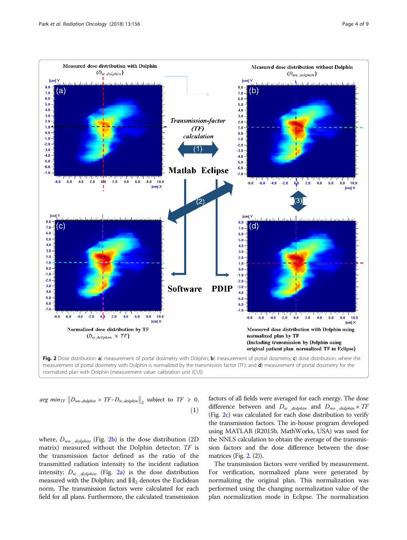
arg minTF Dwo dolphin � TF−Dw dolphin
��
��2 subject to TF ≥ 0;
ð1Þ
where, Dwo _ dolphin (Fig. 2b) is the dose distribution (2Dmatrix) measured without the Dolphin detector; TF isthe transmission factor defined as the ratio of thetransmitted radiation intensity to the incident radiationintensity; Dw _ dolphin (Fig. 2a) is the dose distributionmeasured with the Dolphin; and ‖·‖2 denotes the Euclideannorm. The transmission factors were calculated for eachfield for all plans. Furthermore, the calculated transmission
factors of all fields were averaged for each energy. The dosedifference between and Dw _ dolphin and Dwo _ dolphin ×TF(Fig. 2c) was calculated for each dose distribution to verifythe transmission factors. The in-house program developedusing MATLAB (R2015b, MathWorks, USA) was used forthe NNLS calculation to obtain the average of the transmis-sion factors and the dose difference between the dosematrices (Fig. 2. (2)).The transmission factors were verified by measurement.
For verification, normalized plans were generated bynormalizing the original plan. This normalization wasperformed using the changing normalization value of theplan normalization mode in Eclipse. The normalization
Fig. 2 Dose distribution: a) measurement of portal dosimetry with Dolphin; b) measurement of portal dosimetry; c) dose distribution, where themeasurement of portal dosimetry with Dolphin is normalized by the transmission factor (TF); and d) measurement of portal dosimetry for thenormalized plan with Dolphin (measurement value: calibration unit (CU))
Park et al. Radiation Oncology (2018) 13:156 Page 4 of 9
values were obtained by multiplying the originalnormalization value by the transmission factor of eachenergy (Fig. 2 (3)). After normalization, the monitoringunit (MU) of the normalized plans was equal to the MUof the original plans multiplying normalization values.A patient-specific QA of the normalized plans was
performed using portal dosimetry and an ArcCheckdetector. The dose difference and the gamma indexwere evaluated. The dose difference between the twoplans was calculated, excluding the below-10% dose.Two criteria were applied for the gamma analysis: 2%dose difference (DD) and 2 mm distance to agreement(DTA) and 1% DD and 1 mm DTA. The threshold wasset to 10% dose.The gamma values were calculated to compare the QA
results for the original plan and the normalized planwith the Dolphin detector for both QA devices (e.g.,portal dosimetry and ArcCheck). The gamma index evalu-ation was performed for the predicted dose of the originalplan and the measurement for the normalized plan withthe Dolphin detector.
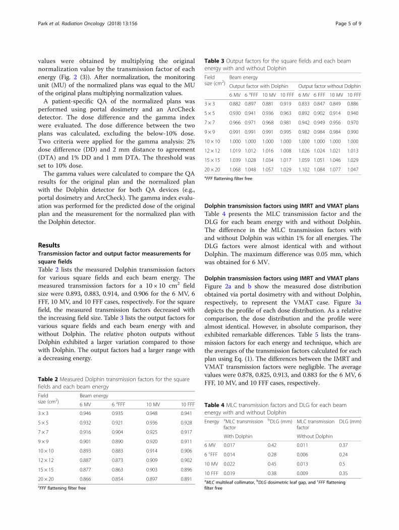
ResultsTransmission factor and output factor measurements forsquare fieldsTable 2 lists the measured Dolphin transmission factorsfor various square fields and each beam energy. Themeasured transmission factors for a 10 × 10 cm2 fieldsize were 0.893, 0.883, 0.914, and 0.906 for the 6 MV, 6FFF, 10 MV, and 10 FFF cases, respectively. For the squarefield, the measured transmission factors decreased withthe increasing field size. Table 3 lists the output factors forvarious square fields and each beam energy with andwithout Dolphin. The relative photon outputs withoutDolphin exhibited a larger variation compared to thosewith Dolphin. The output factors had a larger range witha decreasing energy.
Dolphin transmission factors using IMRT and VMAT plansTable 4 presents the MLC transmission factor and theDLG for each beam energy with and without Dolphin.The difference in the MLC transmission factors withand without Dolphin was within 1% for all energies. TheDLG factors were almost identical with and withoutDolphin. The maximum difference was 0.05 mm, whichwas obtained for 6 MV.
Dolphin transmission factors using IMRT and VMAT plansFigure 2a and b show the measured dose distributionobtained via portal dosimetry with and without Dolphin,respectively, to represent the VMAT case. Figure 3adepicts the profile of each dose distribution. As a relativecomparison, the dose distribution and the profile werealmost identical. However, in absolute comparison, theyexhibited remarkable differences. Table 5 lists the trans-mission factors for each energy and technique, which arethe averages of the transmission factors calculated for eachplan using Eq. (1). The differences between the IMRT andVMAT transmission factors were negligible. The averagevalues were 0.878, 0.825, 0.913, and 0.883 for the 6 MV, 6FFF, 10 MV, and 10 FFF cases, respectively.
Table 2 Measured Dolphin transmission factors for the squarefields and each beam energy
Fieldsize (cm2)
Beam energy
6 MV 6 aFFF 10 MV 10 FFF
3 × 3 0.946 0.935 0.948 0.941
5 × 5 0.932 0.921 0.936 0.928
7 × 7 0.916 0.904 0.925 0.917
9 × 9 0.901 0.890 0.920 0.911
10 × 10 0.893 0.883 0.914 0.906
12 × 12 0.887 0.873 0.909 0.902
15 × 15 0.877 0.863 0.903 0.896
20 × 20 0.866 0.854 0.897 0.891aFFF flattening filter free
Table 3 Output factors for the square fields and each beamenergy with and without Dolphin
Fieldsize (cm2)
Beam energy
Output factor with Dolphin Output factor without Dolphin
6 MV 6 aFFF 10 MV 10 FFF 6 MV 6 FFF 10 MV 10 FFF
3 × 3 0.882 0.897 0.881 0.919 0.833 0.847 0.849 0.886
5 × 5 0.930 0.941 0.936 0.963 0.892 0.902 0.914 0.940
7 × 7 0.966 0.971 0.968 0.981 0.942 0.949 0.956 0.970
9 × 9 0.991 0.991 0.991 0.995 0.982 0.984 0.984 0.990
10 × 10 1.000 1.000 1.000 1.000 1.000 1.000 1.000 1.000
12 × 12 1.019 1.012 1.016 1.008 1.026 1.024 1.021 1.013
15 × 15 1.039 1.028 1.034 1.017 1.059 1.051 1.046 1.029
20 × 20 1.068 1.048 1.057 1.029 1.102 1.084 1.077 1.047aFFF flattening filter free
Table 4 MLC transmission factors and DLG for each beamenergy with and without Dolphin
Energy aMLC transmissionfactor
bDLG (mm) MLC transmissionfactor
DLG (mm)
With Dolphin Without Dolphin
6 MV 0.017 0.42 0.011 0.37
6 cFFF 0.014 0.28 0.006 0.24
10 MV 0.022 0.45 0.013 0.5
10 FFF 0.019 0.38 0.009 0.35aMLC multileaf collimator, bDLG dosimetric leaf gap, and cFFF flatteningfilter free
Park et al. Radiation Oncology (2018) 13:156 Page 5 of 9
The standard deviation was in the range of 0.1–0.3%. The maximum variation between the calculatedtransmission factors was less than 0.8% for all energiesfor VMAT and IMRT.Figure 2c shows the dose distribution obtained with
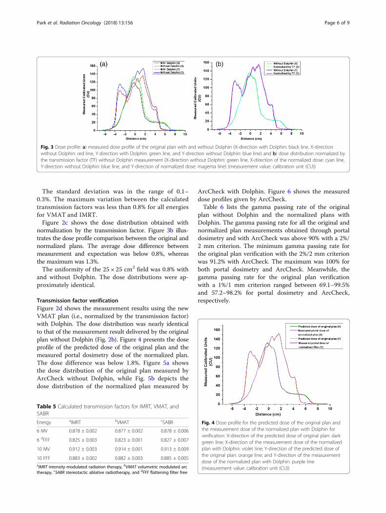
normalization by the transmission factor. Figure 3b illus-trates the dose profile comparison between the original andnormalized plans. The average dose difference betweenmeasurement and expectation was below 0.8%, whereasthe maximum was 1.3%.The uniformity of the 25 × 25 cm2 field was 0.8% with
and without Dolphin. The dose distributions were ap-proximately identical.
Transmission factor verificationFigure 2d shows the measurement results using the newVMAT plan (i.e., normalized by the transmission factor)with Dolphin. The dose distribution was nearly identicalto that of the measurement result delivered by the originalplan without Dolphin (Fig. 2b). Figure 4 presents the doseprofile of the predicted dose of the original plan and themeasured portal dosimetry dose of the normalized plan.The dose difference was below 1.8%. Figure 5a showsthe dose distribution of the original plan measured byArcCheck without Dolphin, while Fig. 5b depicts thedose distribution of the normalized plan measured by
ArcCheck with Dolphin. Figure 6 shows the measureddose profiles given by ArcCheck.Table 6 lists the gamma passing rate of the original
plan without Dolphin and the normalized plans withDolphin. The gamma passing rate for all the original andnormalized plan measurements obtained through portaldosimetry and with ArcCheck was above 90% with a 2%/2 mm criterion. The minimum gamma passing rate forthe original plan verification with the 2%/2 mm criterionwas 91.2% with ArcCheck. The maximum was 100% forboth portal dosimetry and ArcCheck. Meanwhile, thegamma passing rate for the original plan verificationwith a 1%/1 mm criterion ranged between 69.1–99.5%and 57.2–98.2% for portal dosimetry and ArcCheck,respectively.
Fig. 3 Dose profile: a) measured dose profile of the original plan with and without Dolphin (X-direction with Dolphin: black line, X-directionwithout Dolphin: red line, Y-direction with Dolphin: green line, and Y-direction without Dolphin: blue line) and b) dose distribution normalized bythe transmission factor (TF) without Dolphin measurement (X-direction without Dolphin: green line, X-direction of the normalized dose: cyan line,Y-direction without Dolphin: blue line, and Y-direction of normalized dose: magenta line) (measurement value: calibration unit (CU))
Table 5 Calculated transmission factors for IMRT, VMAT, andSABR
Energy aIMRT bVMAT cSABR
6 MV 0.878 ± 0.002 0.877 ± 0.002 0.878 ± 0.006
6 dFFF 0.825 ± 0.003 0.823 ± 0.001 0.827 ± 0.007
10 MV 0.912 ± 0.003 0.914 ± 0.001 0.913 ± 0.009
10 FFF 0.883 ± 0.002 0.882 ± 0.003 0.885 ± 0.005aIMRT intensity-modulated radiation therapy, bVMAT volumetric modulated arctherapy, cSABR stereotactic ablative radiotherapy, and dFFF flattening filter free
Fig. 4 Dose profile for the predicted dose of the original plan andthe measurement dose of the normalized plan with Dolphin forverification: X-direction of the predicted dose of original plan: darkgreen line; X-direction of the measurement dose of the normalizedplan with Dolphin: violet line; Y-direction of the predicted dose ofthe original plan: orange line; and Y-direction of the measurementdose of the normalized plan with Dolphin: purple line(measurement value: calibration unit (CU))
Park et al. Radiation Oncology (2018) 13:156 Page 6 of 9
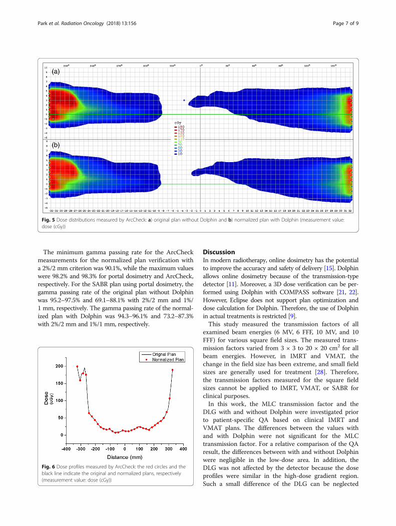
The minimum gamma passing rate for the ArcCheckmeasurements for the normalized plan verification witha 2%/2 mm criterion was 90.1%, while the maximum valueswere 98.2% and 98.3% for portal dosimetry and ArcCheck,respectively. For the SABR plan using portal dosimetry, thegamma passing rate of the original plan without Dolphinwas 95.2–97.5% and 69.1–88.1% with 2%/2 mm and 1%/1 mm, respectively. The gamma passing rate of the normal-ized plan with Dolphin was 94.3–96.1% and 73.2–87.3%with 2%/2 mm and 1%/1 mm, respectively.
DiscussionIn modern radiotherapy, online dosimetry has the potentialto improve the accuracy and safety of delivery [15]. Dolphinallows online dosimetry because of the transmission-typedetector [11]. Moreover, a 3D dose verification can be per-formed using Dolphin with COMPASS software [21, 22].However, Eclipse does not support plan optimization anddose calculation for Dolphin. Therefore, the use of Dolphinin actual treatments is restricted [9].This study measured the transmission factors of all
examined beam energies (6 MV, 6 FFF, 10 MV, and 10FFF) for various square field sizes. The measured trans-mission factors varied from 3 × 3 to 20 × 20 cm2 for allbeam energies. However, in IMRT and VMAT, thechange in the field size has been extreme, and small fieldsizes are generally used for treatment [28]. Therefore,the transmission factors measured for the square fieldsizes cannot be applied to IMRT, VMAT, or SABR forclinical purposes.In this work, the MLC transmission factor and the
DLG with and without Dolphin were investigated priorto patient-specific QA based on clinical IMRT andVMAT plans. The differences between the values withand with Dolphin were not significant for the MLCtransmission factor. For a relative comparison of the QAresult, the differences between with and without Dolphinwere negligible in the low-dose area. In addition, theDLG was not affected by the detector because the doseprofiles were similar in the high-dose gradient region.Such a small difference of the DLG can be neglected
Fig. 5 Dose distributions measured by ArcCheck: a) original plan without Dolphin and b) normalized plan with Dolphin (measurement value:dose (cGy))
Fig. 6 Dose profiles measured by ArcCheck: the red circles and theblack line indicate the original and normalized plans, respectively(measurement value: dose (cGy))
Park et al. Radiation Oncology (2018) 13:156 Page 7 of 9
[29]. Therefore, the same DLG value was used for thedose calculation.This study derived the transmission factors provided
by Dolphin for actual treatment plans and selected vari-ous plans for the measurements. For a relative comparison,the dose distributions were almost identical for measure-ments with and without the transmission detector. In con-trast, an absolute comparison revealed large differences inthe dose value because of the attenuation of the detector.Table 5 shows that the transmission factors were af-
fected by the beam energy only. The delivery technique,MU, and arc range did not influence the transmissionfactor. Our results showed a maximum difference of0.8% for the four energies in each transmission factor.In deriving the transmission factors, the non-negative
least-squares problem solver calculated approximately150,000–850,000 points for each field. The transmissionfactors of all fields were similar for the same energy. Thedose distributions normalized by the transmission factorswere also similar to the dose distributions transmitted byDolphin.The detector design and the electronic parts inside
Dolphin were not uniform [11]. However, each pointhad similar transmission factors. The maximum dosedifference was below 1.7%. Portal dosimetry had a higherresolution than Dolphin because of the detector size ofthe EPID panel. The interior design of Dolphin did notaffect the transmission factors.The gamma passing rates of the patient-specific verifi-
cation demonstrated that the plans normalized by thetransmission factor can be applied for clinical purposeswhen a clinically acceptable criterion (i.e., 2%/2 mm) isused [10]. For the SABR plan, the gamma passing ratesof the original and normalized plans were poor with the1%/1 mm criterion because SABR had small fields andhigh-gradient dose profiles. However, the gamma passingrates of both original and normalized plans were above90% for all cases when 2%/2 mm criteria were applied.The gamma passing rates of the SABR plans were alsowithin an acceptable range (i.e., above 90%) for clinicalpurposes.
ConclusionsThis study derived the transmission factor of the Dolphindetector through the measurement of clinical IMRT andVMAT plans. The transmission factors were determined
for four energies. However, these factors can vary fornominal energies. This study verified only the transmis-sion factors for the beams of our machine; hence, werecommend the verification of the transmission factors forthe beams of each individual machine before clinical use.The Dolphin detector can be an excellent device foronline dosimetry if verified transmission factors are used.
AbbreviationsDD: dose difference; DLG: dosimetric leaf gap; Dmax: depth of maximumdose; DTA: distance to agreement; EPID: electronic portal imaging device;FFF: flattening filter free; IMRT: intensity-modulated radiation therapy;MLC: multileaf collimator; PDD10: percentage depth dose at 10 cm depth;PDIP: portal dose image prediction; QA: quality assurance; SABR: stereotacticablative radiotherapy; TF: transmission factor; TPR 20/10: tissue phantom ratioat the depths of 20 and 10 cm; VMAT: volumetric modulated arc therapy
FundingThis work was supported by the National Research Foundation of Korea (NRF)grant funded by the Korean government (MSIP) (no. NRF-2017R1C1B1006636)and the National R&D Program for Cancer Control, Ministry of Health & Welfare,Republic of Korea (no. 1631200).
Availability of data and materialsData sharing not applicable to this article because no datasets weregenerated or analyzed during the current study.
Authors’ contributionsCHC conceived the study concept, compiled and analyzed the data, draftedthe manuscript, and participated in all aspects of the study. SYL helpedmeasure the data. JMP and SYP analyzed the data from a clinical perspectiveand engaged in discussions to improve the significance of this study. CHCoversaw and verified the study completion. All authors read and approvedthe final manuscript.
Ethics approval and consent to participateNot applicable.
Consent for publicationNot applicable.
Competing interestsThe authors declare that they have no competing interests.
Publisher’s NoteSpringer Nature remains neutral with regard to jurisdictional claims inpublished maps and institutional affiliations.
Author details1Department of Radiation Oncology, Veterans Health Service Medical Center,Seoul, Republic of Korea. 2Institute of Radiation Medicine, Seoul NationalUniversity Medical Research Center, Seoul, Republic of Korea. 3Department ofRadiation Oncology, Seoul National University Hospital, Seoul, Republic ofKorea. 4Biomedical Research Institute, Seoul National University Hospital,Seoul, Republic of Korea.
Table 6 Gamma passing rates of the transmission factor verification measurements in the clinical plans (unit: %)
Criteria Original plan without DolphinAverage ± standard deviation (range)
Normalized plan with DolphinAverage ± standard deviation (range)
Portal dosimetry ArcCheck Portal dosimetry ArcCheck
2%/2 mm 98.1 ± 2.1 (95.2 ~ 100) 97.3 ± 3.2 (91.2 ~ 100) 97.2 ± 2.8 (94.3 ~ 98.2) 96.9 ± 2.9 (90.1 ~ 98.3)
1%/1 mm 82.9 ± 12.6 (69.1 ~ 99.5) 81.4 ± 15.3 (57.2 ~ 98.2) 79.1 ± 14.8 (73.2 ~ 98.3) 75.8 ± 18.8 (61.9 ~ 94.3)
Park et al. Radiation Oncology (2018) 13:156 Page 8 of 9
Received: 29 March 2018 Accepted: 20 August 2018
References1. Georg D, Thwaites D. Medical physics in radiation oncology: new
challenges, needs and roles. Radiother Oncol. 2017;125:375–8.2. Choi CH, Park S-Y, Kim J-i, Kim JH, Kim K, Carlson J, et al. Quality of tri-co-60
MR-IGRT treatment plans in comparison with VMAT treatment plans forspine SABR. Br J Radiol. 2016;90:20160652.
3. Kim J-i, Choi CH, Wu H-G, Kim JH, Kim K, Park JM. Correlation analysisbetween 2D and quasi-3D gamma evaluations for both intensity-modulatedradiation therapy and volumetric modulated arc therapy. Oncotarget. 2017;8(3):5449–59.
4. Vieillevigne L, Molinier J, Brun T, Ferrand R. Gamma index comparison ofthree VMAT QA systems and evaluation of their sensitivity to delivery errors.Phys Med. 2015;31:720–5.
5. Stevens S, Dvorak P, Spevacek V, Pilarova K, Bray-Parry M, Gesner J, et al. Anassessment of a 3D EPID-based dosimetry system using conventionaltwo-and three-dimensional detectors for VMAT. Phys Med. 2018;45:25–34.
6. Liang B, Liu B, Zhou F, F-f Y, Wu Q. Comparisons of volumetric modulatedarc therapy (VMAT) quality assurance (QA) systems: sensitivity analysis tomachine errors. Radiat Oncol. 2016;11:146.
7. Park S-Y, Park JM, Choi CH, Chun M, Han JH, Cho JD, et al. Optimal densityassignment to 2D diode array detector for different dose calculationalgorithms in patient specific VMAT QA. J Radiat Prot Res. 2017;42:9–15.
8. Crowe S, Kairn T, Middlebrook N, Sutherland B, Hill B, Kenny J, et al.Examination of the properties of IMRT and VMAT beams and evaluationagainst pre-treatment quality assurance results. Phys Med Biol. 2015;60:2587.
9. Nakaguchi Y, Ono T, Maruyama M, Shimohigashi Y, Kai Y. Validation of amethod for in vivo 3D dose reconstruction in SBRT using a newtransmission detector. J Appl Clin Med Phys. 2017;18:69–75.
10. Kim J-i, Choi CH, Park S-Y, An H, Wu H-G, Park JM. Gamma evaluation with portalDosimetry for volumetric modulated arc therapy and intensity-modulatedradiation therapy. Prog Med Phys. 2017;28:61–6.
11. Cheung JP, Perez-Andujar A, Morin O. Characterization of the effect of anew commercial transmission detector on radiation therapy beams. PractRadiat Oncol. 2017;7:e559–e67.
12. Ricketts K, Navarro C, Lane K, Blowfield C, Cotten G, Tomala D, et al. Clinicalexperience and evaluation of patient treatment verification with a transitdosimeter. Int J Radiat Oncol Biol Phys. 2016;95:1513–9.
13. van der Bijl E, van Oers RF, Olaciregui-Ruiz I, Mans A. Comparison ofgamma-and DVH-based in vivo dosimetric plan evaluation for pelvic VMATtreatments. Radiother Oncol. 2017;125:405–10.
14. Kamerling CP, Fast MF, Ziegenhein P, Menten MJ, Nill S, Oelfke U. Onlinedose reconstruction for tracked volumetric arc therapy: real-timeimplementation and offline quality assurance for prostate SBRT. Med Phys.2017;44(11):5997–6007.
15. Thoelking J, Fleckenstein J, Sekar Y, Boggula R, Lohr F, Wenz F, et al. Patient-specific online dose verification based on transmission detectormeasurements. Radiother Oncol. 2016;119:351–6.
16. Pasler M, Michel K, Marrazzo L, Obenland M, Pallotta S, Björnsgard M, et al.Error detection capability of a novel transmission detector: a validationstudy for online VMAT monitoring. Phys Med Biol. 2017;62:7440.
17. Rankine LJ, Mein S, Cai B, Curcuru A, Juang T, Miles D, et al. Three-dimensionaldosimetric validation of a magnetic resonance guided intensity modulatedradiation therapy system. Int J Radiat Oncol Biol Phys. 2017;97:1095–104.
18. McCowan P, Asuni G, van Beek T, van Uytven E, Kujanpaa K, McCurdy B. Amodel-based 3D patient-specific pre-treatment QA method for VMAT usingthe EPID. Phys Med Biol. 2017;62:1600.
19. Miori G, Martignano A, Menegotti L, Valentini A. Evaluation of an integral qualitymonitor device for monitoring real-time delivery. Phys Med. 2016;32:42–3.
20. Gonod M, Giordan V, ScandiDos, Aubignac L. 6. ScandiDos’s discover systemevaluation. Phys Med. 2017;44(S1):30.
21. Valve A, Keyriläinen J, Kulmala J. Compass model-based quality assurancefor stereotactic VMAT treatment plans. Phys Med. 2017;44:42–50.
22. Tomsej M, Monseux A, Baltieri V, Leclercq C, Sottiaux A. Assessment ofportal dosimetry accuracy as a QA tool for VMAT clinical treatment plansusing dolphin/compass tools. Phys Med. 2016;32:265.
23. Miri N, Keller P, Zwan BJ, Greer P. EPID-based dosimetry to verify IMRTplanar dose distribution for the aS1200 EPID and FFF beams. J Appl ClinMed Phys. 2016;17:292–304.
24. Yao W, Farr JB. Determining the optimal dosimetric leaf gap setting forrounded leaf-end multileaf collimator systems by simple test fields. J ApplClin Med Phys. 2015;16:65–77.
25. Middlebrook ND, Sutherland B, Kairn T. Optimization of the dosimetric leafgap for use in planning VMAT treatments of spine SABR cases. J Appl ClinMed Phys. 2017;18:133–9.
26. Fuangrod T, Rowshanfarzad P, Greer PB, Middleton RH. A cine-EPID basedmethod for jaw detection and quality assurance for tracking jaw in IMRT/VMAT treatments. Phys Med. 2015;31:16–24.
27. Ding L, Deán-Ben XL, Lutzweiler C, Razansky D, Ntziachristos V. Efficientnon-negative constrained model-based inversion in optoacoustictomography. Phys Med Biol. 2015;60:6733.
28. Oh S, Lewis B, Watson A, Kim S, Kim T. The effect of beam interruptionduring FFF-VMAT plans for SBRT. Australas Phys Eng Sci Med. 2017;40:931–8.
29. Mullins J, DeBlois F, Syme A. Experimental characterization of the dosimetricleaf gap. Biomed Phys Eng Express. 2016;2:065013.
Park et al. Radiation Oncology (2018) 13:156 Page 9 of 9


![Power hardware in the loop validation of fault ride ... · advantages over the HVAC transmission system [3–6]. The choice between a HVAC and a HVDC transmission system depends upon](https://img.pdfslide.us/doc/110x75/5ebf935af4163c04dc17b09f/power-hardware-in-the-loop-validation-of-fault-ride-advantages-over-the-hvac.jpg)