Embed Size (px)
Citation preview
FM 24-19
RADIO OPERATOR’S HANDBOOK
DISTRIBUTION RESTRICTION: Distribution authorized to U.S. Government agencies and their contractors only to protect technical or operational information from automatic dissemination under the International Exchange Program or by other means. This determination was made on 15 October 1990. Other requests for this document will be referred to Commander, U.S. Army Signal Center and Fort Gordon, ATTN: ATZH-DHL, Fort Gordon, GA 30905-5075. DESTRUCTION NOTICE: Destroy by any method that will prevent disclosure of contents or reconstruction of the document.
HEADQUARTERS, DEPARTMENT OF THE ARMY
Field Manual *FM 24-19No 24-19 Headquarters,
Department of the ArmyWashington, DC, 24 May 1991
DISTRIBUTION RESTRICTION: Approved for public release ; distr ibut ion is unl imited.
*This publication supersedes TC 24-19, 24 June 1985.
i
FM 24-19
ii
FM 24-19
i i i
FM 24-19
i v
FM 24-19
v
FM 24-19
v i
FM 24-19
v i i
viii
i x
x

x i
FM 24-19
x i i
FM 24-19
P r e f a c e
P u r p o s e a n d S c o p eThis field manual gives the single-channel radio operator
a reference for cabling, operating, remoting, and trouble-shooting single-channel radio teletypewriter sets and thepower generating sets used with them. This manual is ar e a d y r e f e r e n c e f o r s o m e b a s i c r a d i o c o m m u n i c a t i o n sprocedures. It is designed for carrying in the pocket. Theinformation is detailed only to the extent needed as a quickreference for day-to-day operat ions . For more completedetails, refer to the respective TM, ACP, or FM.
U s e r I n f o r m a t i o nThe proponent of this publication is HQ TRADOC. Your
comments on this publ icat ion are encouraged. Submitchanges for improving this publication on DA Form 2028(Recommended Changes to Publications and Blank Forms)and key them to pages and lines of text to which they apply.If DA Form 2028 is not available, a letter is acceptable.Provide reasons for your comments to ensure completeu n d e r s t a n d i n g a n d p r o p e r e v a l u a t i o n . F o r w a r d y o u rcomments to Commander, United States Army Signal Centerand Fort Gordon, ATTN: ATZH-DTL, Fort Gordon, Georgia30905-5075.
x i i i
FM 24-19
CHAPTER 1Radio and RadioTeletypewriter Sets
Section I. Radio Set AN/GRC-106
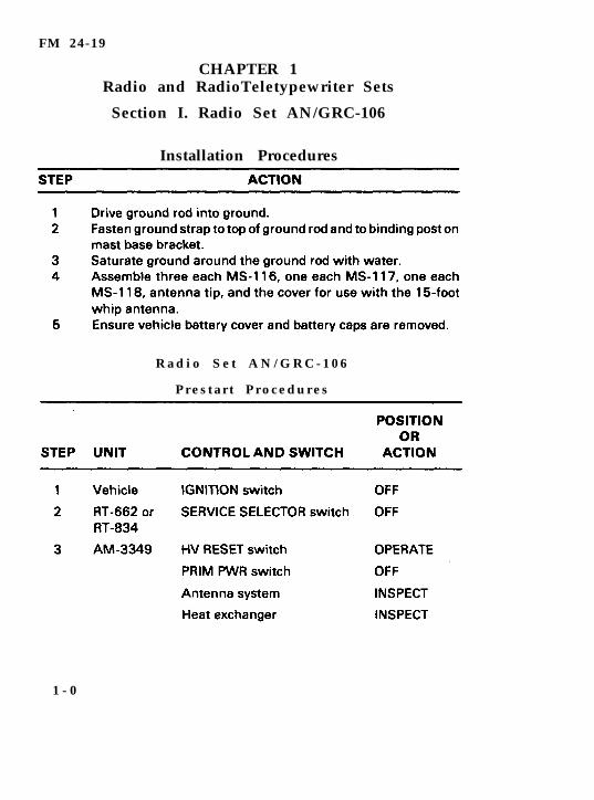
Installation Procedures
R a d i o S e t A N / G R C - 1 0 6
P r e s t a r t P r o c e d u r e s
1 - 0
FM 24-19
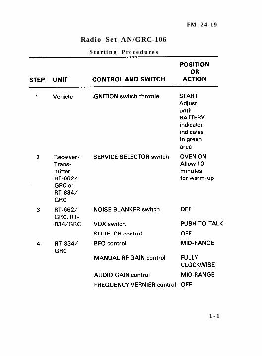
Radio Set AN/GRC-106
S t a r t i n g P r o c e d u r e s
1 - 1
FM 24-19
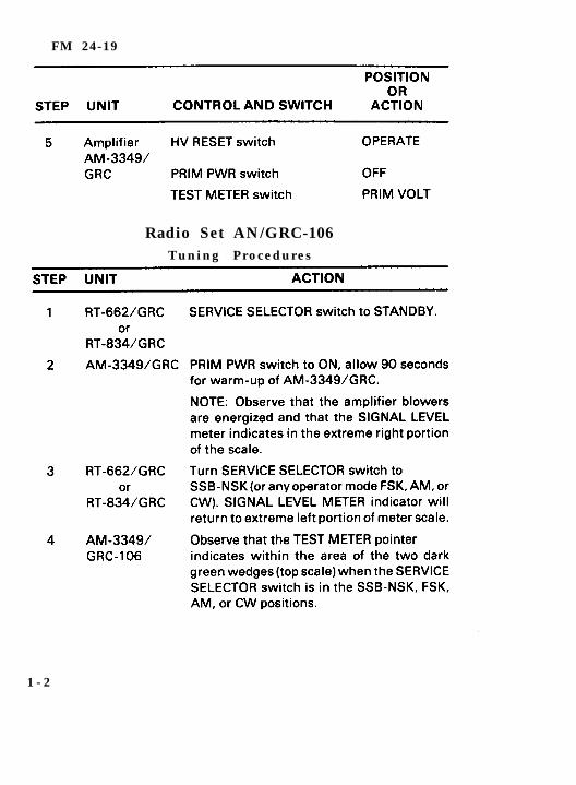
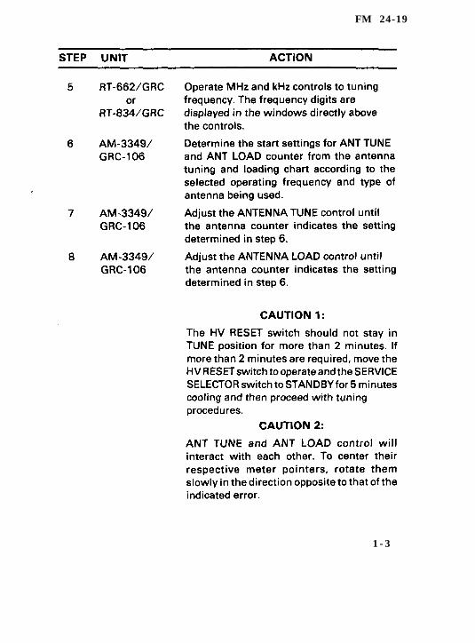
Radio Set AN/GRC-106Tuning Procedures
1 - 2
FM 24-19
1 - 3
FM 24-19
1 - 4
FM 24-19
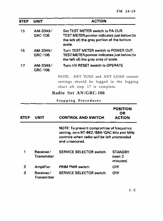
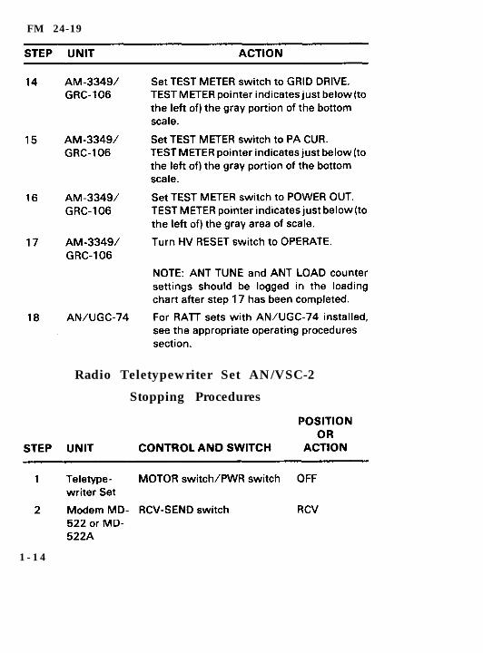
NOTE: ANT TUNE and ANT LOAD countersettings should be logged in the loggingchart aft step 17 is complete.
Radio Set AN/GRC-106
S t o p p i n g P r o c e d u r e s
1 - 5

FM 24-19
1 - 6
FM 24-19
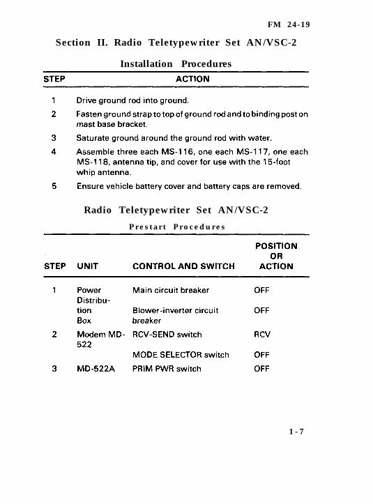
Section II. Radio Teletypewriter Set AN/VSC-2
Installation Procedures
Radio Teletypewriter Set AN/VSC-2
P r e s t a r t P r o c e d u r e s
1 - 7
FM 24-19
1 - 8
FM 24-19
1-9
FM 24-19
1 - 1 0

FM 24-19
Radio Teletypewriter Set AN/VSC-2Tuning Procedures
1 - 1 1
F M 2 4 - 1 9
1-12
FM 24-19
1-13
FM 24-19
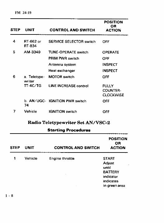
Radio Teletypewriter Set AN/VSC-2
Stopping Procedures
1 - 1 4
FM 24-19
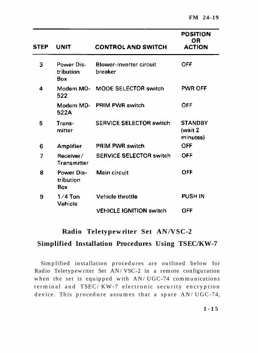
Radio Teletypewriter Set AN/VSC-2
Simplified Installation Procedures Using TSEC/KW-7
Simplified installation procedures are outlined below forRadio Teletypewriter Set AN/VSC-2 in a remote configurationwhen the set is equipped with AN/UGC-74 communicationsterminal and TSEC/KW-7 e lectronic securi ty encrypt iondevice. This procedure assumes that a spare AN/UGC-74,
1 - 1 5
FM 24-19
data cable, and TSEC/KW-7 are not available. If monitoringthe radio teletypewriter set is desired, these items must befurnished separately. If these items are furnished separatelyand monitoring is desired, skip step 1 below.
S T E P 1 .
S T E P 2 .
S T E P 3 .
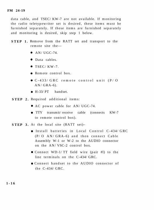
Remove from the RATT set and transport to theremote site the—
AN/UGC-74.
Data cables.
TSEC/KW-7.
Remote control box.
C - 4 3 3 / G R C r e m o t e c o n t r o l u n i t ( P / OAN/GRA-6).
H-33/PT handset.
Required additional items:
AC power cable for AN/UGC-74.
TTY transmit/receive cable (connects KW-7to remote control box).
At the local site (RATT set)–
Insta l l bat ter ies in Local Control C-434/GRC (P/O AN/GRA-6) and then connect CableAssembly W-1 or W-2 to the AUDIO connectoron the AN/VSC-2 control box.
Connect WD-1/TT field wire (pair #l) to theline terminals on the C-434/GRC.
Connect handset to the AUDIO connector ofthe C-434/GRC.
1 - 1 6
FM 24-19
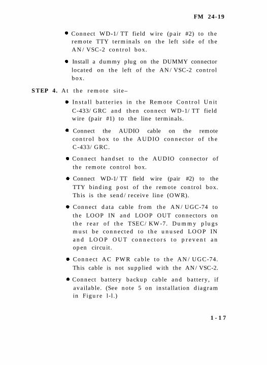
Connect WD-1/TT field wire (pair #2) to theremote TTY terminals on the left side of theAN/VSC-2 control box.
Install a dummy plug on the DUMMY connectorlocated on the left of the AN/VSC-2 controlbox.
STEP 4. At the remote site–
Install batteries in the Remote Control UnitC-433/GRC and then connect WD-1/TT fieldwire (pair #1) to the line terminals.
Connect the AUDIO cable on the remotecontrol box to the AUDIO connector of theC-433/GRC.
Connect handset to the AUDIO connector ofthe remote control box.
Connect WD-1/TT field wire (pair #2) to theTTY binding post of the remote control box.This is the send/receive line (OWR).
Connect data cable from the AN/UGC-74 tothe LOOP IN and LOOP OUT connectors onthe rear of the TSEC/KW-7. Dummy plugsmust be connected to the unused LOOP INand LOOP OUT connectors to prevent anopen circuit.
Connect AC PWR cable to the AN/UGC-74.This cable is not supplied with the AN/VSC-2.
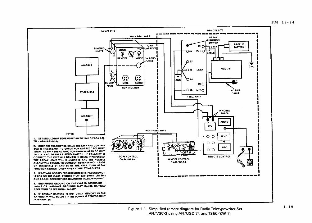
Connect battery backup cable and battery, ifavailable. (See note 5 on installation diagramin Figure l-l.)
1 - 1 7
FM 24-19
Instal l equipment grounds on AN/UGC-74and TSEC/KW-7. Good equipment groundsare essential for operation and safety.
CAUTION
Do not attempt to operate equipment withoutgrounds.
1 - 1 8
F M 1 9 - 2 4
1 - 1 9
FM 24-19
Radio Teletypewriter Set AN/VSC-2
Simplified Installation Procedural Using TSEC/KG-84A
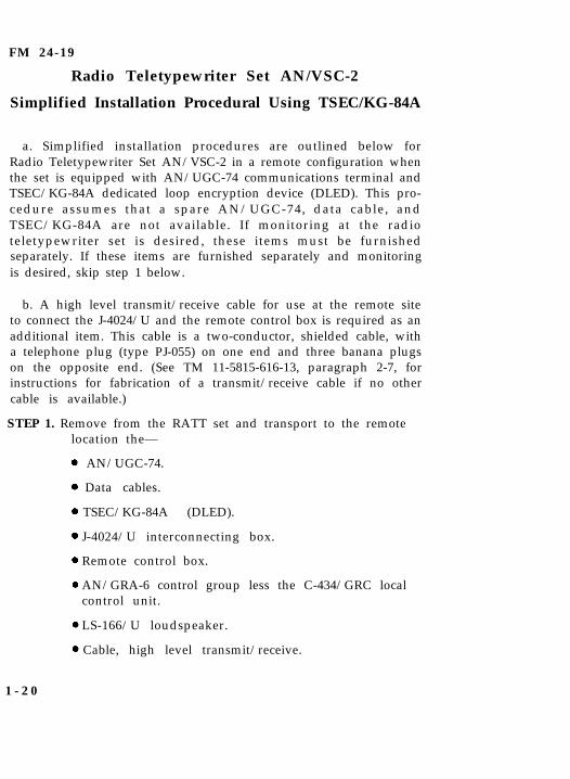
a. Simplified installation procedures are outlined below forRadio Teletypewriter Set AN/VSC-2 in a remote configuration whenthe set is equipped with AN/UGC-74 communications terminal andTSEC/KG-84A dedicated loop encryption device (DLED). This pro-cedure assumes that a spare AN/UGC-74, data cable, andTSEC/KG-84A are not available. If monitoring at the radioteletypewriter set is desired, these items must be furnishedseparately. If these items are furnished separately and monitoringis desired, skip step 1 below.
b. A high level transmit/receive cable for use at the remote siteto connect the J-4024/U and the remote control box is required as anadditional item. This cable is a two-conductor, shielded cable, witha telephone plug (type PJ-055) on one end and three banana plugson the opposite end. (See TM 11-5815-616-13, paragraph 2-7, forinstructions for fabrication of a transmit/receive cable if no othercable is available.)
STEP 1. Remove from the RATT set and transport to the remotelocation the—
AN/UGC-74.
Data cables.
TSEC/KG-84A (DLED).
J-4024/U interconnecting box.
Remote control box.
AN/GRA-6 control group less the C-434/GRC localcontrol unit.
LS-166/U loudspeaker.
Cable, high level transmit/receive.
1 - 2 0
FM 24-19
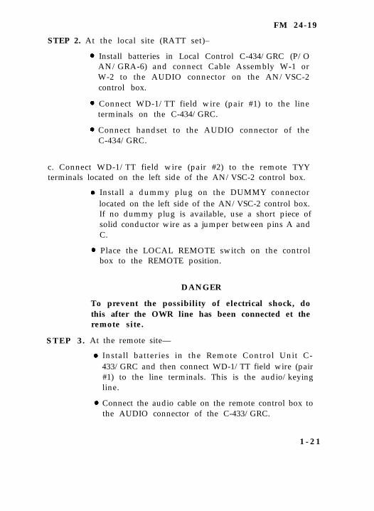
STEP 2. At the local site (RATT set)–
Install batteries in Local Control C-434/GRC (P/OAN/GRA-6) and connect Cable Assembly W-1 orW-2 to the AUDIO connector on the AN/VSC-2control box.
Connect WD-1/TT field wire (pair #1) to the lineterminals on the C-434/GRC.
Connect handset to the AUDIO connector of theC-434/GRC.
c. Connect WD-1/TT field wire (pair #2) to the remote TYYterminals located on the left side of the AN/VSC-2 control box.
Install a dummy plug on the DUMMY connectorlocated on the left side of the AN/VSC-2 control box.If no dummy plug is available, use a short piece ofsolid conductor wire as a jumper between pins A andC.
Place the LOCAL REMOTE switch on the controlbox to the REMOTE position.
STEP 3 .
DANGER
To prevent the possibility of electrical shock, dothis after the OWR line has been connected et theremote site.
At the remote site—
Install batteries in the Remote Control Unit C-433/GRC and then connect WD-1/TT field wire (pair#1) to the line terminals. This is the audio/keyingline.
Connect the audio cable on the remote control box tothe AUDIO connector of the C-433/GRC.
1 - 2 1

FM 24-19
Connect J-654/G interconnecting box to the AUDIOconnector of the remote control box. Connect thehandset and speaker to the J-654/G.
Connect WD-1/TT field wire (pair #2) to the TTYbinding post of the remote control box. This is thesend-receive line (OWR).
Connect the transmit/receive cable banana plugs toJ-4024/U terminals L1 (send) and L3 (receive). Connecta jumper wire between terminals L2 and L4. Connectthe banana plug that is attached to the shield wire tothe ground terminal.
Connect the transmit/receive cable telephone plugto the remote control box terminal J1.
Connect DLED power cable (CX-13315/U) fromTSEC/KG-84A (J1) to J-4024/U (J4).
Connect DLED black cable (CX-13317/U) fromTSEC/KG-84A (J2) to J-4024/U (Jl).
Connect DLED red cable (CX-13316/U) fromTSEC/KG-84A (J3) to J-4024/U (J2).
Connect data cable (SC-D-960024) from theAN/UGC-74 to the J5 and J7 (TTY 1) connectors onthe J-4024/U.
Connect AC power cable to AN/UGC-74. (This cableis not supplied with the AN/VSC-2. Requisitionpower cable assembly, 5995-00-271-9444, fromTM 11-5815-602-10.)
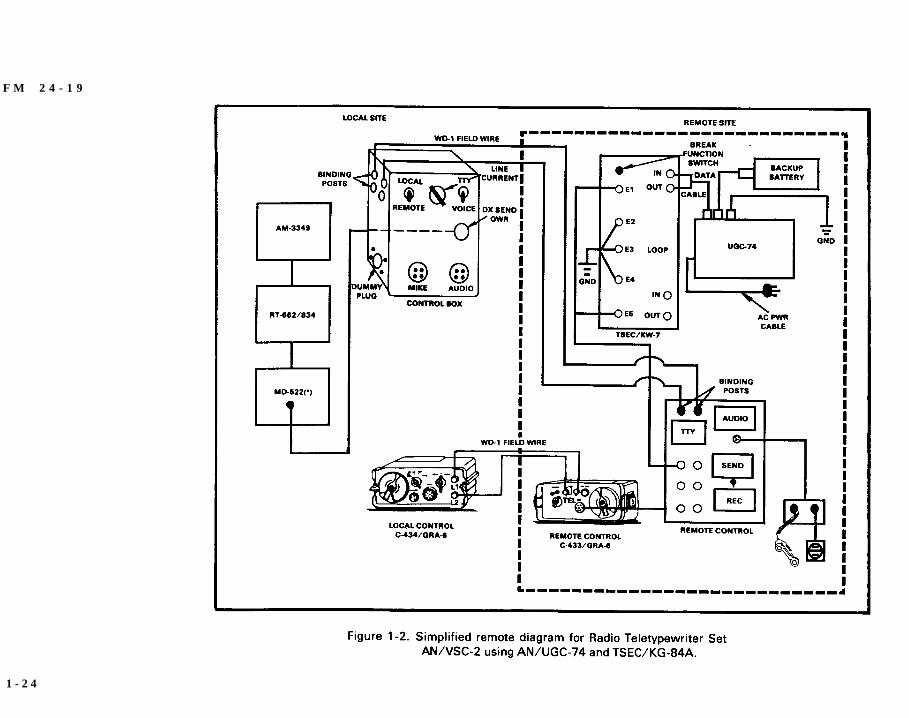
Connect battery backup cable and battery, ifavailable. (See note 5 on the installation diagram inFigure 1-2.)
Install quipment grounds on AN/UGC-74, J-4024/U,and TSEC/KG-84A. Good equipment grounds areessential for operation and safety.
1 - 2 2

FM 24-19
Operational procedures are the same for theAN/VSC-2.
CAUTIONDo not attempt to operate equipment without grounds.
1 - 2 3
F M 2 4 - 1 9
1 - 2 4
FM 24-19
Section III. Radio Teletypewriter Set AN/VSC-3
Operating Instructions
The following procedures cover local AN/VSC-3 operationincluding the Intercommunications Set AN/VIC-l(V).
CAUTION 1Before applying primary power to the AN/VSC-3, start the M577A1engine or auxiliary power unit. Failure to do this may cause seriousdamage to the radio equipment.
CAUTION 2When teletypewriter is not transmitting, the auxiliary REC-SENDswitch, the MD-522 (*)/GRC SEND-REC switch, and the remote controlREC-SEND switch must be set to REC to prevent transmitter from beingcontinuously keyed.
Radio Teletypewriter Set AN/VSC-3
Prestart Operating Procedures
Before starting any of the equipment, perform the followingprocedures:
a. Control Box.
(1) Set main circuit breaker to OFF.
(2) Set inverter circuit breaker to OFF.
b. MX-7778/GRC. Set circuit breakera to OFF.
c. Radio Set AN/GRC-106(*). Set PRIM PWR switch on theAM-3349/GRC-106 to OFF. Set SERVICE SELECTORswitch on RT-662/GRC or RT-834/GRC to OFF.
d. Radio Teletypewriter Modem MD-522(*)/GRC. Set ON-OFFswitch to OFF.
1 - 2 5
FM 24-19
e. Teletypewriter Set TT-98(*)/FG.
(1) Set MOTOR switch to OFF.
(2) Set LIGHT switch to OFF.
(3) Adjust TT-98(*)/FG LINE CURRENT control fullyclockwise (for minimum resistance).
(4) Set LINE SELECTOR switch to 20 MA position.
f. Teletypewriter, Reperforator-Transmitter TT-76(*)/GGC.
(1) Set PWR switch to OFF.
(2) Set MOTOR switch to OFF.
(3) Set LIGHT switch to OFF.
(4) Check the current in the bias circuit by following theinstructions in TM 11-5815-238-10.
(5) Open the TT-76(*)/GGC cover and perform the followingprocedures if TTY security equipment is to be installed. Ifnot, skip (5), (6), and (7).
Ensure a 5600-ohm resistor is connected to the powersupply and terminal unit BIAS TEST MA terminals, inplace of the shorting strap.
Ensure the SIGNAL/BIAS switch on the power supplyand terminal unit is in the 60 MA position (60 MA is thecorrect position when using the 5600-ohm resistor in (a)even though the system is set for 20 MA).
Ensure the plug from the selector magnet cable is in thesocket marked 20 MA.
(6) Close the set cover.
(7 ) Ensure that Device , Low Level S ignal ing TT-523(*)/GGC is correctly installed on the set behind thetransmitter-distributor. Ensure the plugs are connected
1 - 2 6

FM 24-19
and the bracket is secured under the binding post on theside of the set cover.
Radio Teletypewriter Set AN/VSC-3
Starting Procedures
Start the M577A1 engine or auxiliary power and perform theprocedures below.
a. On the control box, perform the following:
Set the main circuit breakers to ON, and observe that the 27.5VDC indicator lights and the DC voltmeter indicates 27.5VDC.
Set the inverter breaker to ON, and observe that the inverteris operating.
Set the VOICE-CW/TTY switch to TTY.
If the AN\VSC-3 is to be operated in a NONSECURE mode,set the BLACK-RED switch to BLACK. If the AN/VSC-3 is tobe operated in a SECURE mode, set the BLACK-RED switchto RED.
Set the LOCAL-REMOTE switch to LOCAL.
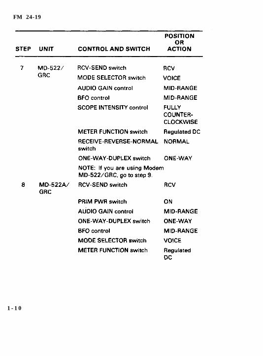
b. On the MD-522(*)/GRC, open the control cover to exposeadditional controls and complete the following:
Set the ONE-WAY-DUPLEX switch to ONE WAY.
Set the RECEIVE switch to NORM.
Set the METER FUNCTION switch to DC LOOP 1.
Set the DC LOOP 1 switch to 20 MA.
Set the SCOPE INTENSITY control FULLYCOUNTERCLOCKWISE.
Set the BFO control to ita midscale position.
1 - 2 7
FM 24-19
Set the AUDIO GAIN control FULLYCOUNTERCLOCKWISE.
Set the MODE SELECTOR switch to VOICE.
Set the RCV-SEND switch to RCV.
Set the AUTO MARK HOLD switch to ON.
Set the SQUELCH SENS control to the FULLYCLOCKWISE position.
Set the ON-OFF switch to ON.
c. Set the MX-7778/GRC circuit breakers to ON.
d. Set the auxiliary RCV-SEND switch (on the shelf) to RCV.
e. On the TT-98(*)/FG, set the MOTOR switch to ON, LIGHTswitch to ON, and SEND-LOCK switch to SEND.
f. On the TT-76(*)/GGC, set the POWER ON/OFF switch toON, MOTOR ON/OFF switch to ON, LIGHT ON/OFFswitch to ON, KEYBOARD SEND/LOCK switch to SEND,and SELECTOR switch to POSITION 1.
g. Send a line of RYs on the TT-98(*)/FG keyboard, and ensurethe TT-98(*)/FG and the TT-76(*)/GGC are printing andperforating tape in response.
h. Send a line of RYs on the TT-76(*)/GGC keyboard. Ensure theTT-76(*)/GGC is printing and perforating tape, and the TT-98(*)/FG is printing in response.
i. Insert a prepunched tape into the TT-76(*)/GGC transmitter-distributor. Set the transmitter-distributor, and set thetransmitter-distributor START-STOP lever to START. Ensurethe TT-76(*)/GGC is printing and perforating tape, and theTT-98(*)/FG is printing in response. Set the transmitter-distributor START-STOP lever to STOP.
j. Set the TT-76(*)/GGC SELECTOR switch to position 2. Setthe transmitter-distributor START-STOP switch to START.
1 - 2 8
FM 24-19
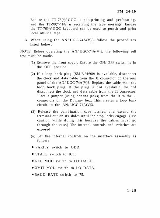
Ensure the TT-76(*)/GGC is not printing and perforating,and the TT-98(*)/FG is receiving the tape message. Ensurethe TT-76(*)/GGC keyboard can be used to punch and printlocal off-line tape.
k. When using the AN/UGC-74A(V)3, follow the procedureslisted below.
NOTE: Before operating the AN/UGC-74A(V)3, the following selftest must be made.
(1) Remove the front cover. Ensure the ON/OFF switch is inthe OFF position.
(2) If a loop back plug (SM-B-91600) is available, disconnectthe clock and data cable from the J1 connector on the rearpanel of the AN/UGC-74A(V)3. Replace the cable with theloop back plug. If the plug is not available, do notdisconnect the clock and data cable from the J1 connector.Place a jumper (using banana jacks) from the B to the Cconnectors on the Dummy box. This creates a loop backcircuit to the AN/UGC-74A(V)3.
(3) Release the combination case latches, and extend theterminal out on its slides until the stop locks engage. (Usecaution while doing this because the cables must gothrough the case.) The internal controls and switches areexposed.
(a) Set the internal controls on the interface assembly asfollows.
PARITY switch to ODD.
STATE switch to ICT.
REC MOD switch to LO DATA.
XMIT MOD switch to LO DATA.
BAUD RATE switch to 75.
1 - 2 9
FM 24-19
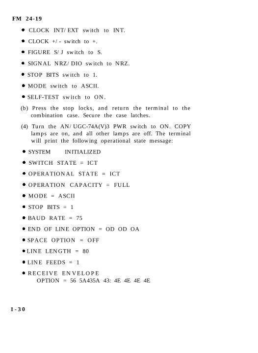
CLOCK INT/EXT switch to INT.
CLOCK +/- switch to +.
FIGURE S/J switch to S.
SIGNAL NRZ/DIO switch to NRZ.
STOP BITS switch to 1.
MODE switch to ASCII.
SELF-TEST switch to ON.
(b) Press the stop locks, and return the terminal to thecombination case. Secure the case latches.
(4) Turn the AN/UGC-74A(V)3 PWR switch to ON. COPYlamps are on, and all other lamps are off. The terminalwill print the following operational state message:
SYSTEM INITIALIZED
SWITCH STATE = ICT
OPERATIONAL STATE = ICT
OPERATION CAPACITY = FULL
MODE = ASCII
STOP BITS = 1
BAUD RATE = 75
END OF LINE OPTION = OD OD OA
SPACE OPTION = OFF
LINE LENGTH = 80
LINE FEEDS = 1
R E C E I V E E N V E L O P EOPTION = 56 5A435A 43: 4E 4E 4E 4E
1 - 3 0
FM 24-19
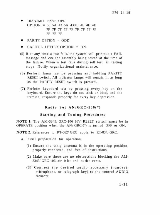
TRANSMIT ENVELOPEOPTION = 56 5A 43 5A 43:4E 4E 4E 4E
7F 7F 7F 7F 7F 7F 7F 7F 7F7F 7F 7F
PARITY OPTION = ODD
CAPITOL LETTER OPTION = ON
(5) If at any time a test fails, the system will printout a FAILmessage and cite the assembly being tested at the time ofthe failure. When a test fails during self test, all testingstops. Notify organizational maintenance.
(6) Perform lamp test by pressing and holding PARITYRESET switch. All indicator lamps will remain lit as longas the PARITY RESET switch is pressed.
(7) Perform keyboard test by pressing every key on thekeyboard. Ensure the keys do not stick or bind, and theterminal responds properly for every key depression.
R a d i o S e t A N / G R C - 1 0 6 ( * )
Start ing and Tuning Procedures
NOTE 1: The AM-3349/GRC-106 HV RESET switch must be inOPERATE position when the AN/GRC-(*) is turned OFF or ON.
NOTE 2: References to RT-662/GRC apply to RT-834/GRC.
a. Initial preparation for operation.
(1) Ensure the whip antenna is in the operating position,properly connected, and free of obstructions.
(2) Make sure there are no obstructions blocking the AM-3349/GRC-106 air inlet and outlet vents.
(3) Connect the des ired audio accessory (handset ,microphone, or telegraph key) to the control AUDIOconnector.
1 - 3 1
FM 24-19
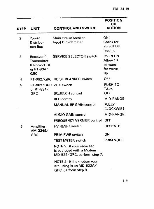
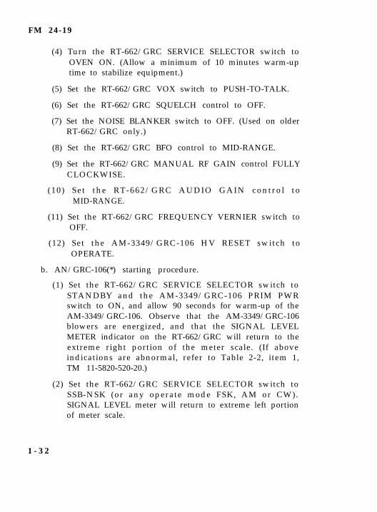
(4) Turn the RT-662/GRC SERVICE SELECTOR switch toOVEN ON. (Allow a minimum of 10 minutes warm-uptime to stabilize equipment.)
(5) Set the RT-662/GRC VOX switch to PUSH-TO-TALK.
(6) Set the RT-662/GRC SQUELCH control to OFF.
(7) Set the NOISE BLANKER switch to OFF. (Used on olderRT-662/GRC only.)
(8) Set the RT-662/GRC BFO control to MID-RANGE.
(9) Set the RT-662/GRC MANUAL RF GAIN control FULLYCLOCKWISE.
(10) Set the RT-662/GRC AUDIO GAIN control toMID-RANGE.
(11) Set the RT-662/GRC FREQUENCY VERNIER switch toOFF.
(12) Set the AM-3349/GRC-106 HV RESET switch toOPERATE.
b. AN/GRC-106(*) starting procedure.
(1) Set the RT-662/GRC SERVICE SELECTOR switch toSTANDBY and the AM-3349/GRC-106 PRIM PWRswitch to ON, and allow 90 seconds for warm-up of theAM-3349/GRC-106. Observe that the AM-3349/GRC-106blowers are energized, and that the SIGNAL LEVELMETER indicator on the RT-662/GRC will return to theextreme right portion of the meter scale. (If aboveindications are abnormal, refer to Table 2-2, item 1,TM 11-5820-520-20.)
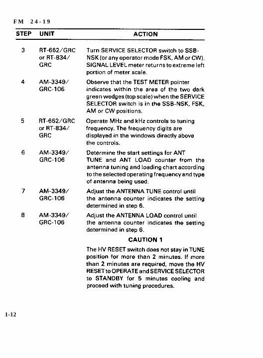
(2) Set the RT-662/GRC SERVICE SELECTOR switch toSSB-NSK (or any operate mode FSK, AM or CW).SIGNAL LEVEL meter will return to extreme left portionof meter scale.
1 - 3 2
FM 24-19
(3) Set the AM-3349/GRC-106 TEST METER switch to PRIMVOLT. Observe that the TEST METER pointer indicateswithin the area of the two dark green wedges (top scale)when the SERVICE SELECTOR switch is in the SSB-NSK, FSK, AM, or CW positions. (If above indication isabnormal, refer to Table 2-2, item 2, TM 11-5820-520-20.)
c. Final tuning procedures for AN/GRC-106(*).
(1) Set the RT-662/GRC MHz and kHz controls to assignedoperating frequency. The frequency digits are displayedin the windows directly above the controls.
(2) Note the AM-3349/GRC-106 ANT TUNE and ANT LOADpredetermined setting on the antenna tuning and loadingchart or the logging chart.
(3) Adjust the AM-3349/GRC-106 ANT TUNE control tomatch the numbers on the chart used.
(4) Adjust the AM-3349/GRC-106 ANT LOAD control tomatch the numbers on the chart used.
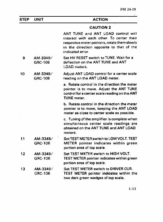
CAUTIONThe HV RESET switch should not stay in TUNE position for more than 2minutes. If more than 2 minutes are required, move the AM-3349/GRC-106 HV RESET switch to OPERATE and the RT-662/GRCSERVICE SELECTOR switch to STANDBY for 5 minutes cooling. After5 minutes cooling, set the SERVICE SELECTOR switch to the previousposition and the HV RESET switch to TUNE, and proceed with the tuningprocedure. ANT TUNE and ANT LOAD controls will interact with eachother. To center their respective meter pointers, rotate them slowly inthe direction opposite that of the indicated error. Be sure the antenna isattached for proper loading to prevent damage to the equipment whileperforming (5) through (12).
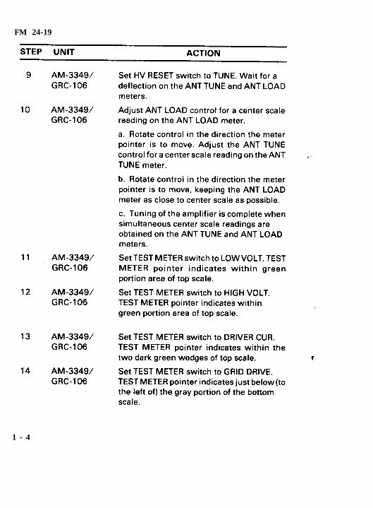
(5) Set the AM-3349/GRC-106 HV RESET switch to TUNE.Wait for a deflection on the ANT TUNE and ANT LOADmeters.
1 - 3 3
FM 24-19
(6) Adjust the AM-3349/GRC-106 ANT LOAD control for acenter scale reading on the ANT LOAD meter.
(a) Rotate control in the direction the meter pointer is tomove. Adjust the ANT TUNE control for a center scalereading on the ANT TUNE meter.
(b) Rotate control in the direction that the meter pointer is tomove, keeping the ANT LOAD meter as close to centerscale as possible.
(c) Tuning of the AM-3349/GRC-106 is complete whensimultaneous center scale readings are obtained on theANT TUNE and ANT LOAD meters. (If indication isabnormal, refer to Table 2-2, item 5, TM 11-5820-520-20.)Place the HV RESET switch of the AM-3349/GRC-106 tothe OPERATE posi t ion. Place the TEST METERFUNCTION switch of the AM-3349/GRC-106 to thePRIM VOLT position. Place the HV RESET switch on theAM-3349/GRC-106 to the TUNE position and observethat the TEST METER pointer indicates within the twodark green wedges (top scale) of the test meter.
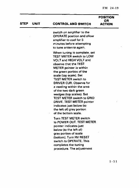
(7) Set the AM-3349/GRC-106 TEST METER switch to LOWVOLT. TEST METER pointer indicates within greenportion of top scale. (For abnormal indication, refer toTable 2-2, item 3, TM 11-5820-520-20.)
(8) Set the AM-3349/GRC-106 TEST METER switch toHIGH VOLT. TEST METER pointer indicates withingreen portion of top scale. (For abnormal indication, referto Table 2-2, item 4, TM 11-5820-520-20.)
(9) Set the AM-3349/GRC-106 TEST METER switch toDRIVE CUR. TEST METER pointer indicates within thetwo dark green wedges of top scale. (For abnormalindication, refer to Table 2-2, item 6, TM 11-5820-520-20.)
(10) Set the AM-3349/GRC-106 TEST METER switch to GRIDDRIVE. TEST METER pointer indicates just below (to
1 - 3 4
FM 24-19
the left of) gray portion of the bottom scale. (For abnormalindication, refer to Table 2-2, item 6, TM 11-5820-520-20.)
(11) Set the AM-3349/GRC-106 TEST METER switch to PACUR. TEST METER pointer indicates just below (to theleft of) the gray portion of the bottom scale. (For abnormalindication, refer to Table 2-2, item 6, TM 11-5820-520-20.)
(12) Set the AM-3349/GRC-106 TEST METER switch toPOWER OUT. TEST METER pointer indicates just below(to the left of) gray portion of scale. (For abnormalindication, refer to Table 2-2, item 6, TM 11-5820-520-20.)
CAUTIONThe HV RESET switch should not stay in TUNE position for more than2 minutes.
(13) Turn the AM-3349/GRC-106 HV RESET switch toOPERATE.
NOTE: ANT TUNE and ANT LOAD counter settings should be logged inthe logging chart with a pencil after (13) above has been completed.These settings may be used for future tuning references unless ANTTUNE and ANT LOAD meter pointers indicate in the red (left or right ofcenter scale) portion of the scale during operation. If the settings cannotbe used, repeat tuning procedures(1) through (13).
I n t e r c o m m u n i c a t i o n s S e t A N / V I C - 1 ( V )
S t a r t i n g P r o c e d u r e s
Turn on and prepare the AN/VIC-1(V) for intercommunicationand AN/GRC-106(*) operation as follows:
Set the AM-1780/VRC POWER CRT BKR ON/OFF switch toON, and observe that the POWER indicator lights.
Set the AM-1780/VRC MAIN PWR switch to INT ONLY.
Set the AM-1780/VRC INT ACCENT ON/OFF switch to ON.
1 - 3 5
FM 24-19
Set the AM-1780/VRC RADIO TRANSMISSION switch toCDR + CREW.
Set the AM-1780/VRC INSTALLATION SWITCH toOTHER.
Operate each crew box (C-2298/VRC) on interphone to checkAN/VIC-1(V) system.
I n t e r c o m m u n i c a t i o n s S e t A N / V I C - 1 ( V )
Local Operation
a. Radio Teletypewriter Reception.
NOTE: MD-522(*)/GRC is provided with an automatic MARKHOLD. With the AUTO MARK HOLD switch in the ON position,the teletypewriter will not open during the period of no signals orwhen signals are too weak for interchangeability.
(1) On the RT-662/GRC, set the SERVICE SELECTORswitch to SSB/NSK or FSK as required. Set theMANUAL RF GAIN control fully clockwise and theAUDIO GAIN control at midposition.
(2) Set the MD-522(*)/GRC MODE SELECTOR switch to850 Hz, 85 Hz, or 85 Hz DIV, as required.
(3) Set the MD-522(*)/GRC AUDIO GAIN control for acomfortable level of audio on the incoming tones from thedistant station.
(4) Adjust MD-522(*)/GRC BFO control (on 850 Hz only) fortwo clean ellipses on the cathode ray tube when a signalhaving proper speed and shift is being received.
(5) When signal is received, set TT-98(*)/FG MOTORON/OFF switch to ON and/or set the TT-76(*)/GGCSELECTOR switch to position 1, as desired, to receivemessage on the respective teletypewriter. Adjust MD-522(*)/GRC BFO control (on 850 Hz only) slightly toeliminate errors in received copy.
1 - 3 6
FM 24-19
b. Radio Teletypewriter Transmission.
(1) Set the RCV-SEND switch on MD-522(*)/GRC to SEND.Set the auxiliary RCV-SEND switch (on the shelf) toSEND.
(2) Operate the TT-76(*)/GGC or TT-98(*)/FG to sendmessage.
(3) Immediately after sending message, set the auxiliaryRCV-SEND switch back to RCV.
c. Voice or CW Communications.
(1) On the RT-662/GRC, set the SERVICE SELECTORswitch to SSB/NSK or CW as required. Set MANUAL RFGAIN and AUDIO GAIN controls as cited in a (l).
(2) Set the MD-522(*)GRC MODE SELECTOR to VOICE.
(3) Set the MD-522(*)GRC AUDIO GAIN control for acomfortable level of audio on the incoming voice or CWsignal.
(4) Set the VOICE-CW/TTY switch on the AN/VSC-3 controlbox to VOICE-CW. Turn the control box INVERTERswitch to OFF.
(5) Observe that the control box NONSECURE VOICEindicator lamp is on.
(6) Operate the controls at the appropriate operator position.
(7) When the AN/GRC-106(*) is to be operated in the CWmode, disconnect cable W21 from the control box AUDIOconnector and connect Telegraph Key KY-116/U to theconnector.
(8) When the AN/GRC-106(*) is to be operated in the VOICEmode without the AN/VIC-1(V), connect Headset H-33/PT or Microphone M-29/U to the control box AUDIOconnector.
1 - 3 7
FM 24-19
I n t e r c o m m u n i c a t i o n s S e t A N / V I C - 1 ( V )
S t o p p i n g P r o c e d u r e s
a. Set PWR switches on the AN/VIC-1(V), MD-522(*)/GRC,TT-76(*)/GGC, and TT-98(*)/FG to OFF.
b. Set the RT-662/GRC or RT-834/GRC SERVICE SELECTORswitch to STANDBY. Allow 2 minutes for the AN/GRC-106(*)to cool. Keep the HV RESET switch on the AM-3349/GRC-106at OPERATE position when AN/GRC-106(*) is turned OFFor ON. After 2 minutes cooling, set the AM-3349/GRC-106PRIM PWR switch and the RT-662/GRC or RT-834/GRCSERVICE SELECTOR switch to OFF.
c. Set the inverter and main circuit breakers on the AN/VSC-3control box to OFF.
d. Perform the stopping procedures to shut down.
NOTE: For troubleshooting the VSC-3, see troubleshooting chartson the AN/GRC-122/142. The only difference is the control boxAM-1780.
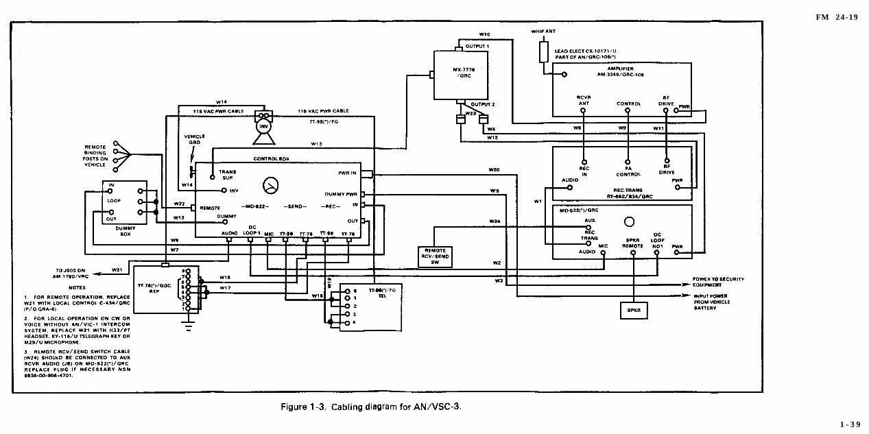
R a d i o T e l e t y p e w r i t e r S e t A N / V S C - 3 ( * )
Cabling Diagrams
Basic operation of the radio teletypewriter set is the same as forthe Radio Teletypewriter Set AN/GRC-142. For detailed instruc-tions on operation, refer to TM 11-5815-332-15. Figures 1-3 and 1-4show a cabling diagram for the AN/VSC-3(*).
1 - 3 8
FM 24-19
1 - 3 9

FM 24-19
1 - 4 0
FM 24-19
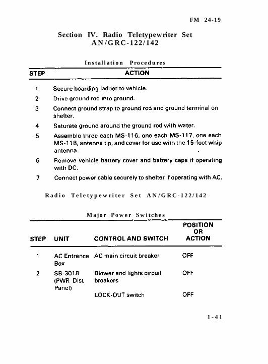
Section IV. Radio Teletypewriter SetAN/GRC-122/142
Instal lat ion Procedures
R a d i o T e l e t y p e w r i t e r S e t A N / G R C - 1 2 2 / 1 4 2
Major Power Switches
1 - 4 1

FM 24-19
1 - 4 2
FM 24-19
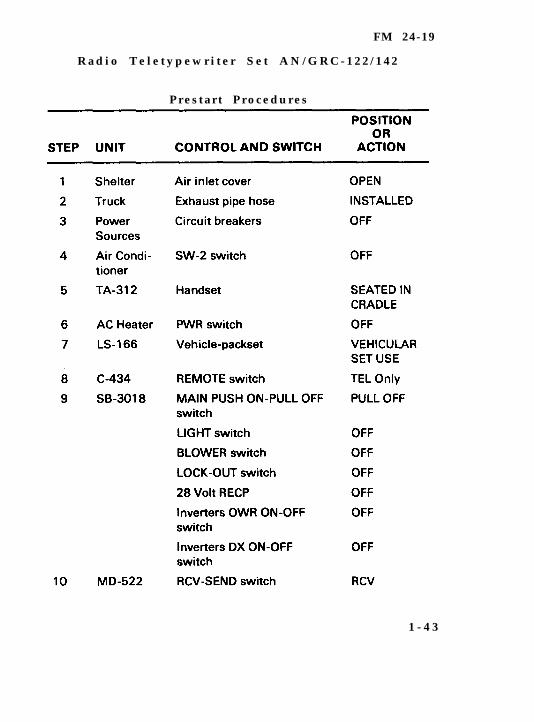
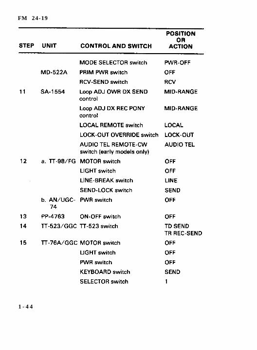
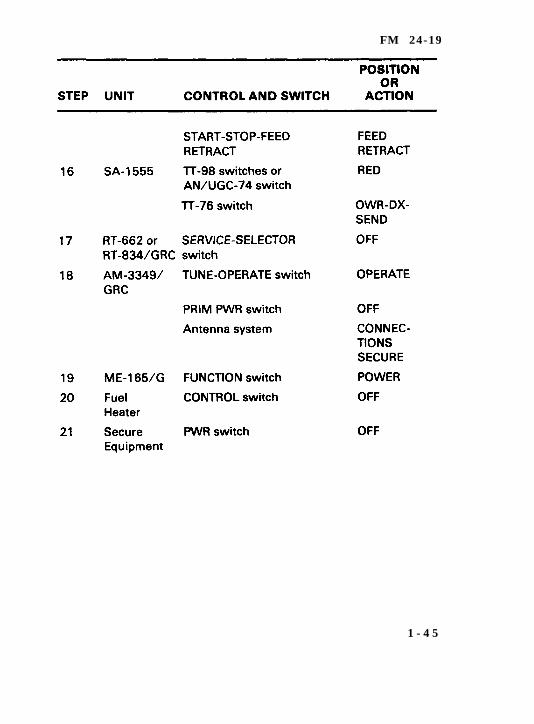
R a d i o T e l e t y p e w r i t e r S e t A N / G R C - 1 2 2 / 1 4 2
P r e s t a r t P r o c e d u r e s
1 - 4 3
FM 24-19
1 - 4 4
FM 24-19
1 - 4 5
FM 24-19
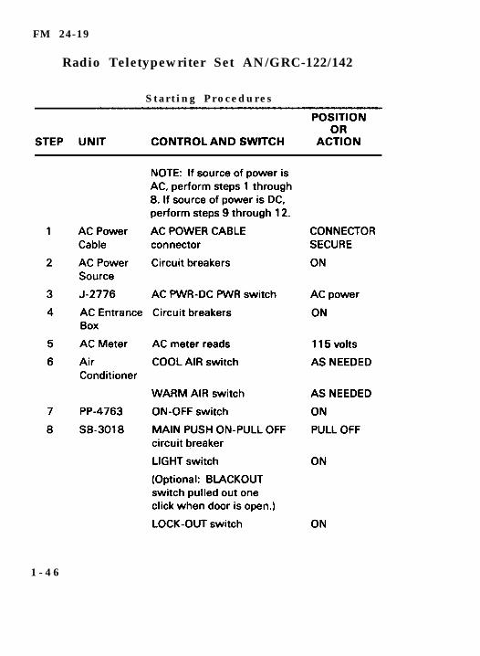
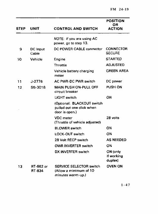
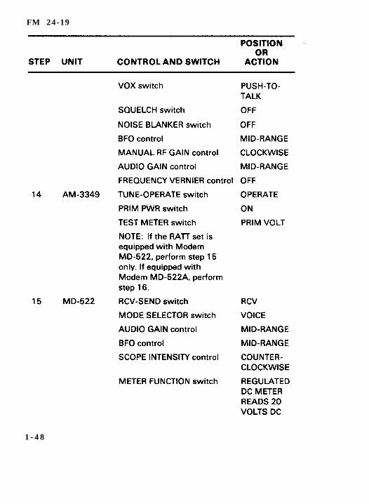
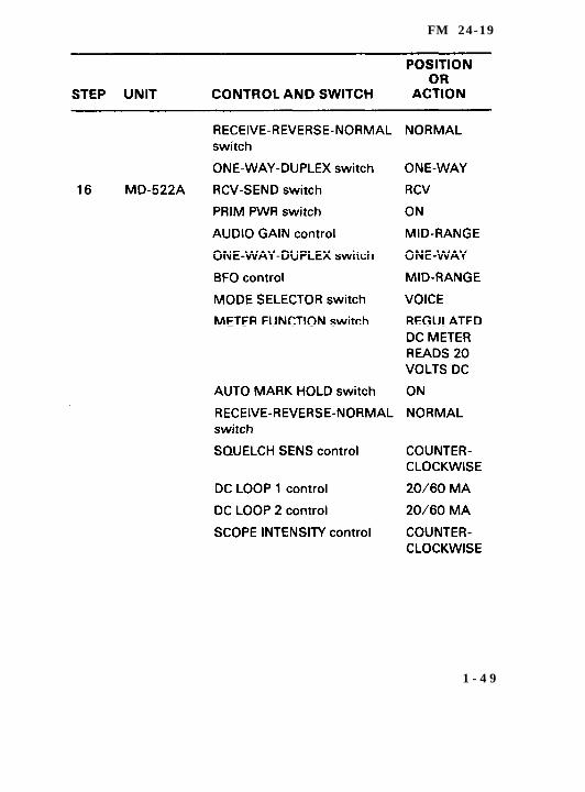
Radio Teletypewriter Set AN/GRC-122/142
S t a r t i n g P r o c e d u r e s
1 - 4 6
FM 24-19
1 - 4 7
FM 24-19
1 - 4 8
FM 24-19
1 - 4 9
FM 24-19
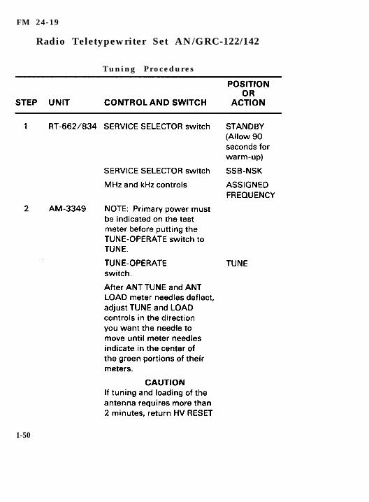
Radio Teletypewriter Set AN/GRC-122/142
Tuning Procedures
1-50
FM 24-19
1 - 5 1
FM 24-19
1 - 5 2
FM 24-19
1 - 5 3
FM 24-19
Radio Teletypewriter Set AN/GRC-122/142
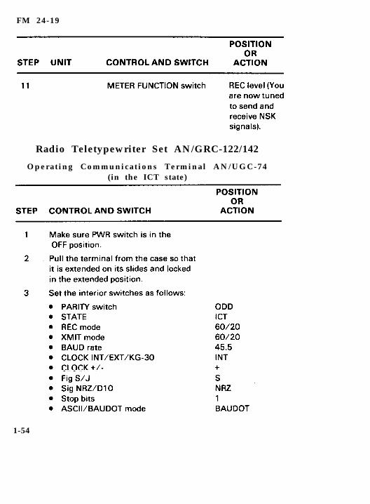
Operating Communications Terminal AN/UGC-74(in the ICT state)
1-54
FM 24-19
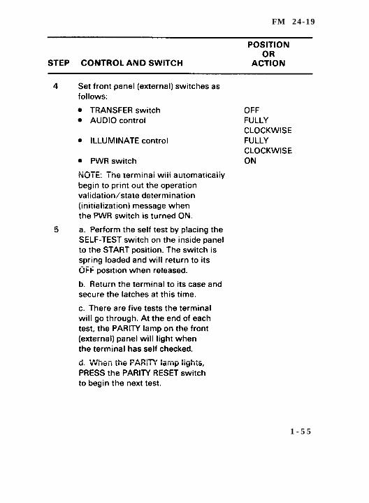
1 - 5 5
FM 24-19
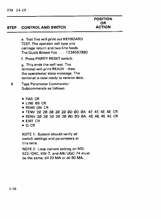
1-56
FM 24-19
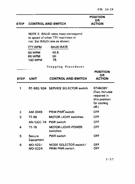
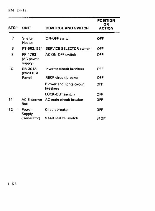
S t o p p i n g P r o c e d u r e s
1 - 5 7
FM 24-19
1 - 5 8
FM 24-19
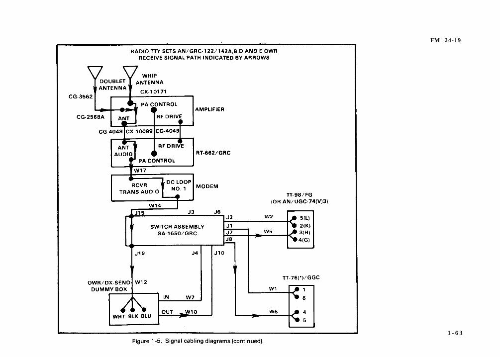
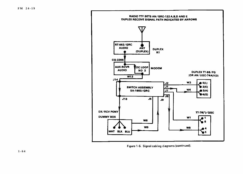
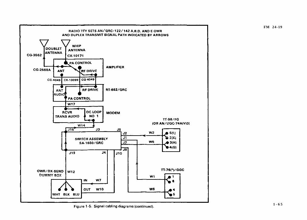
Radio Teletypewriter Set AN/GRC-122/142
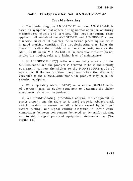
T r o u b l e s h o o t i n g
a. Troubleshooting the AN/GRC-122 and the AN/GRC-142 isbased on symptoms that appear during normal operation or duringmaintenance checks and services. The troubleshooting chartapplies to all models of the AN/GRC-122 and AN/GRC-142 unlessotherwise indicated. It assumes the vehicular generating system isin good working condition. The troubleshooting chart helps theoperator localize the trouble to a particular unit, such as theAN/GRC-106 or the MD-522/GRC. If the corrective measures do notresolve the trouble, refer to a higher level of maintenance.
b. If AN/GRC-122/142(*) radio sets are being operated in theSECURE mode and the problem is believed to be in the securityequipment, convert the shelter to the NONSECURE mode ofoperation. If the malfunction disappears when the shelter isconverted to the NONSECURE mode, the problem may be in thesecurity equipment.
c. When operating AN/GRC-122(*) radio sets in DUPLEX modeof operation, turn off duplex equipment to determine the sheltercomponent related to the problem.
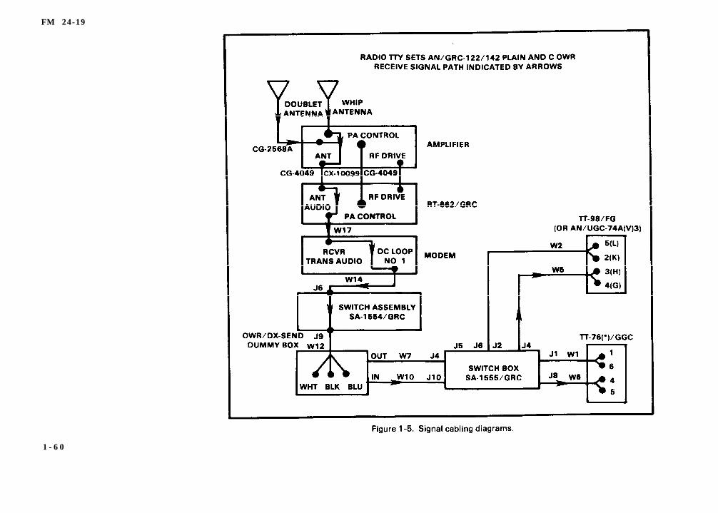
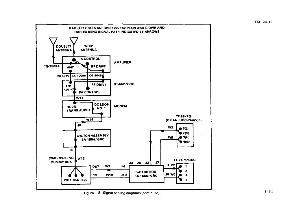
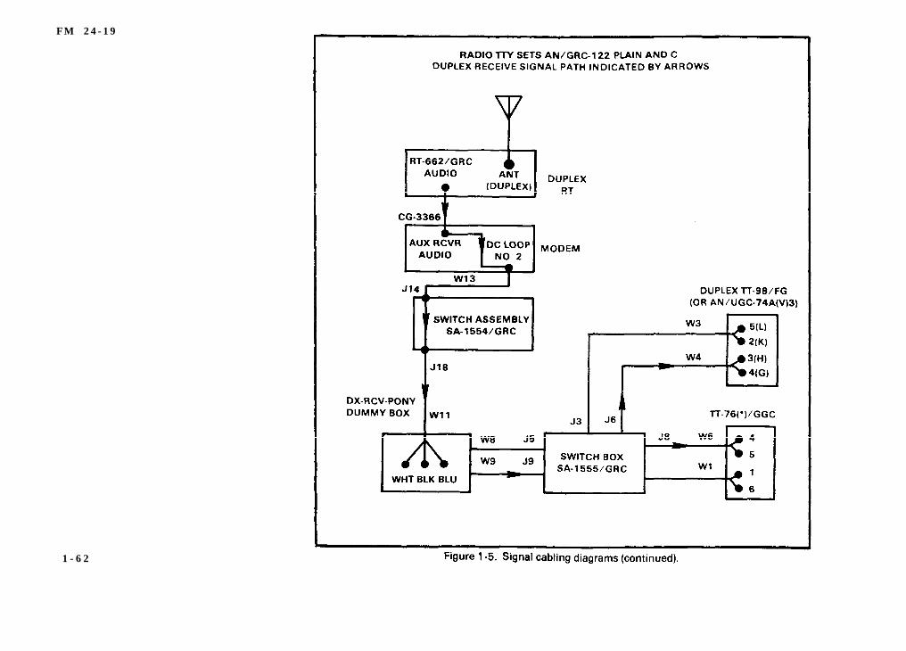
d. All troubleshooting procedures assume the equipment ispreset properly and the radio set is tuned properly. Always checkswitch positions to ensure the failure is not caused by improperswitch setting. Use signal cabling diagrams to locate cableconnections between components believed to be malfunctioningand to aid in signal path and equipment interconnections. (SeeFigure 1-5.)
1 - 5 9
FM 24-19
1 - 6 0
FM 24-19
1 - 6 1
F M 2 4 - 1 9
1 - 6 2
FM 24-19
1 - 6 3
F M 2 4 - 1 9
1 - 6 4
FM 24-19
1 - 6 5
FM 24-19
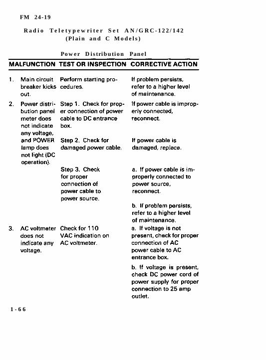
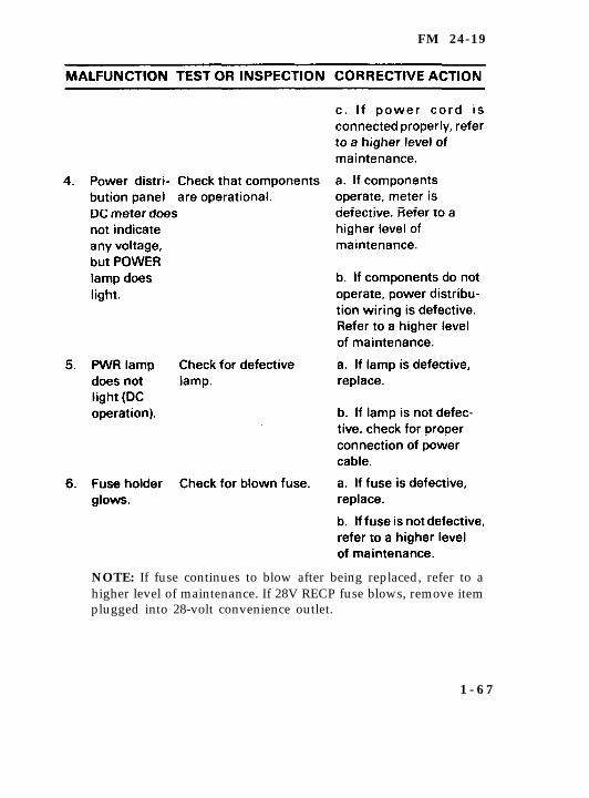
R a d i o T e l e t y p e w r i t e r S e t A N / G R C - 1 2 2 / 1 4 2(Plain and C Models)
Power Distribution Panel
1 - 6 6
FM 24-19
NOTE: If fuse continues to blow after being replaced, refer to ahigher level of maintenance. If 28V RECP fuse blows, remove itemplugged into 28-volt convenience outlet.
1 - 6 7
FM 24-19
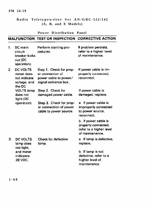
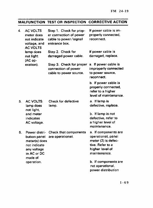
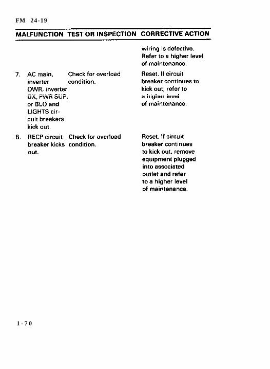
R a d i o T e l e t y p e w r i t e r S e t A N / G R C - 1 2 2 / 1 4 2(A, B, and E Models)
Power Distribution Panel
1 - 6 8
FM 24-19
1 - 6 9
FM 24-19
1 - 7 0
FM 24-19
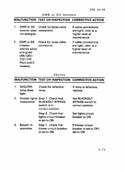
OWR or DX Inverters
S h e l t e r
1 - 7 1
FM 24-19
1 - 7 2
FM 24-19
O p e r a t i o n
1 - 7 3
FM 24-19
1 - 7 4
FM 24-19
1 - 7 5
FM 24-19
1 - 7 6

FM 24-79
1 - 7 7
FM 24-19
1 - 7 8
FM 24-19
1 - 7 9
FM 24-19
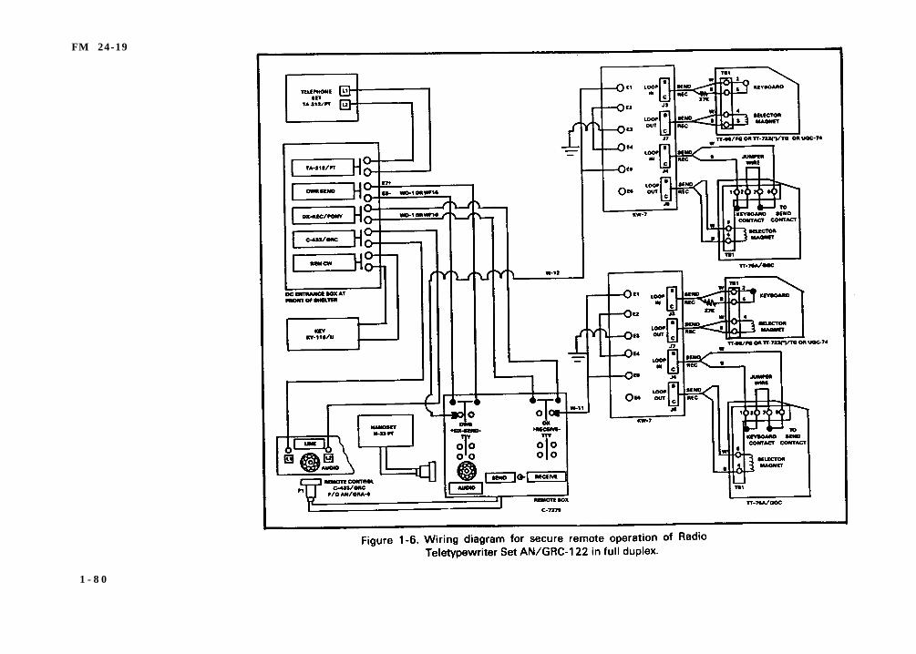
1 - 8 0
F M 2 4 - 1 9
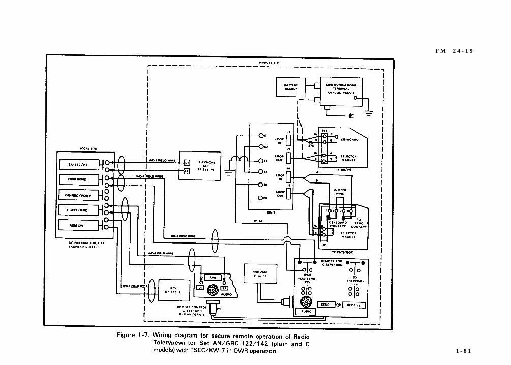
1 - 8 1
FM 24-19
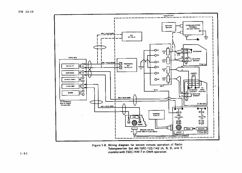
1 - 8 2
F M 2 4 - 1 9
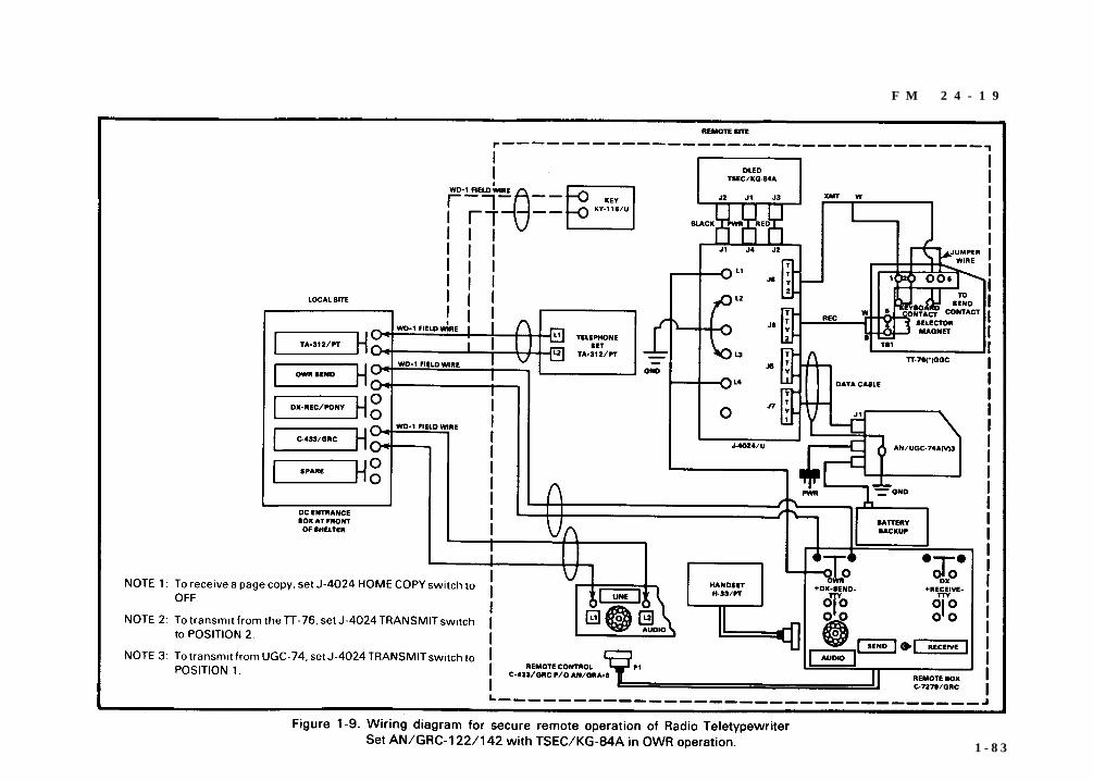
1 - 8 3
FM 24-19
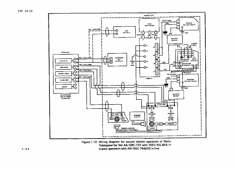
1 - 8 4
F M 2 4 - 1 9
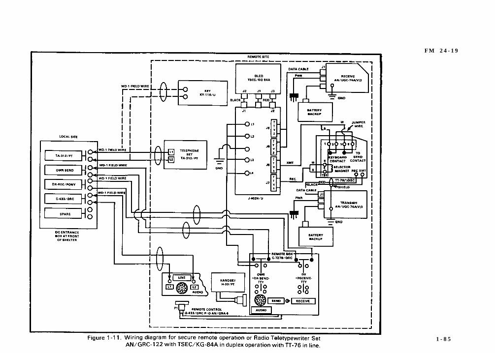
1 - 8 5
FM 24-19
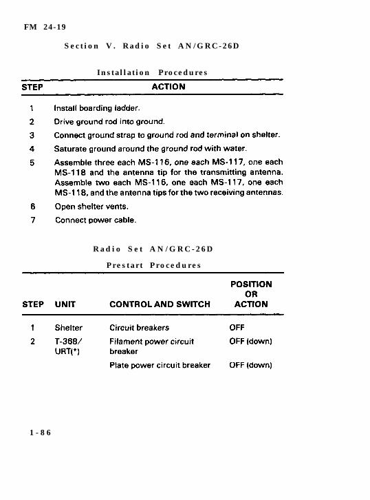
S e c t i o n V . R a d i o S e t A N / G R C - 2 6 D
Instal lat ion Procedures
R a d i o S e t A N / G R C - 2 6 D
P r e s t a r t P r o c e d u r e s
1 - 8 6
FM 24-19
1 - 8 7
FM 24-19
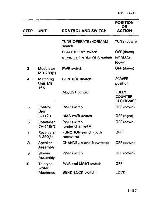
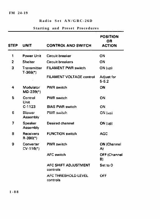
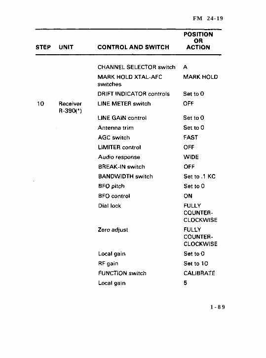
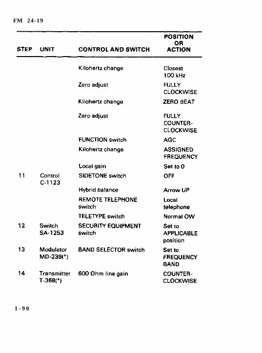
R a d i o S e t A N / G R C - 2 6 D
Start ing and Preset Procedures
1 - 8 8
FM 24-19
1 - 8 9
FM 24-19
1 - 9 0

FM 24-19
NOTE: When operating in the 10-20 MHz range, the LOWFREQUENCY INCREASE control for the 2-10 MHz range must be set to30.
1 - 9 1
FM 24-19
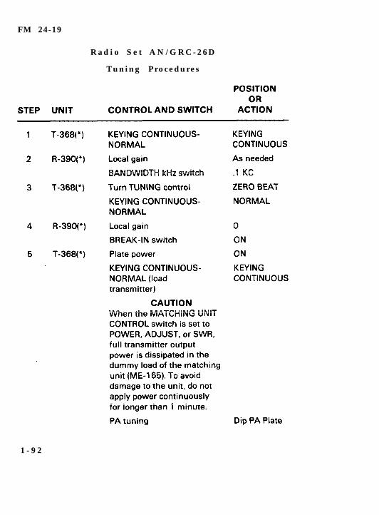
R a d i o S e t A N / G R C - 2 6 D
Tuning Procedures
1 - 9 2
FM 24-19
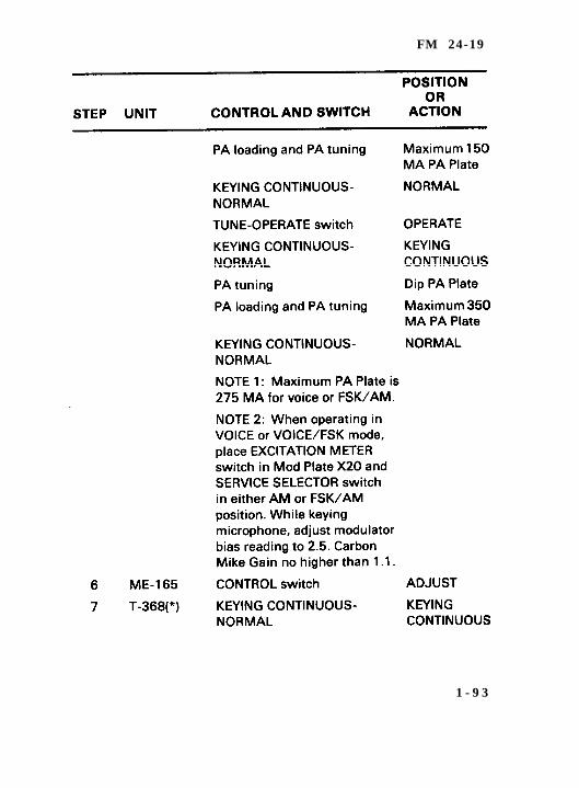
1 - 9 3
FM 24-19
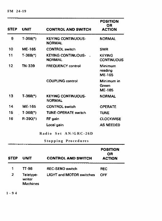
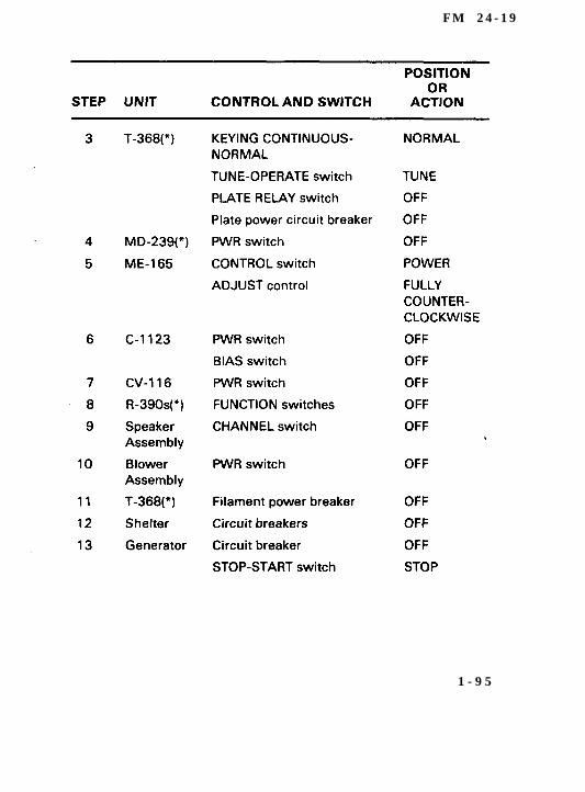
R a d i o S e t A N / G R C - 2 6 D
S t o p p i n g P r o c e d u r e s
1 - 9 4
F M 2 4 - 1 9
1 - 9 5
FM 24-19
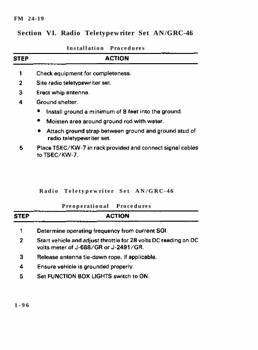
Section VI. Radio Teletypewriter Set AN/GRC-46
Instal lat ion Procedures
R a d i o T e l e t y p e w r i t e r S e t A N / G R C - 4 6
Preoperat ional Procedures
1 - 9 6
FM 24-19
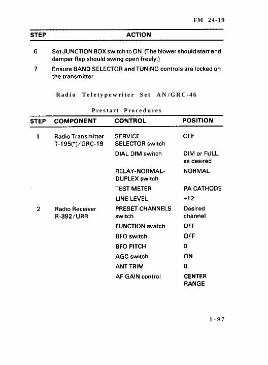
R a d i o T e l e t y p e w r i t e r S e t A N / G R C - 4 6
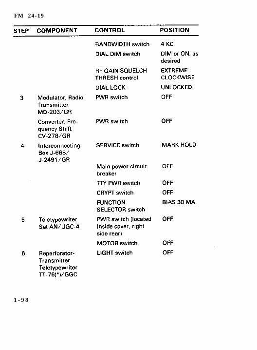
P r e s t a r t P r o c e d u r e s
1 - 9 7
FM 24-19
1 - 9 8
FM 24-19
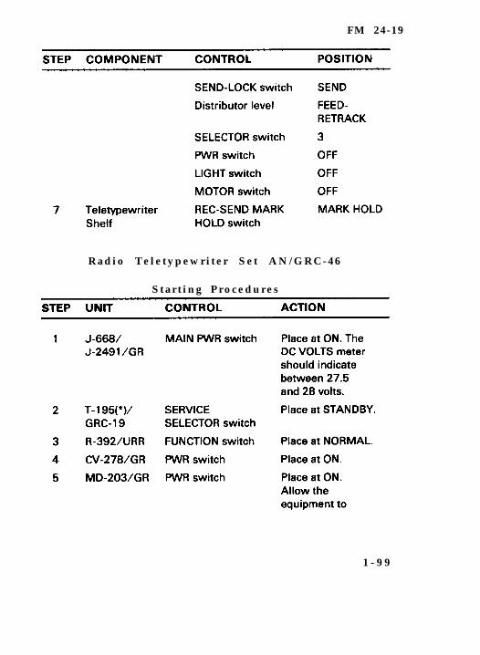
R a d i o T e l e t y p e w r i t e r S e t A N / G R C - 4 6
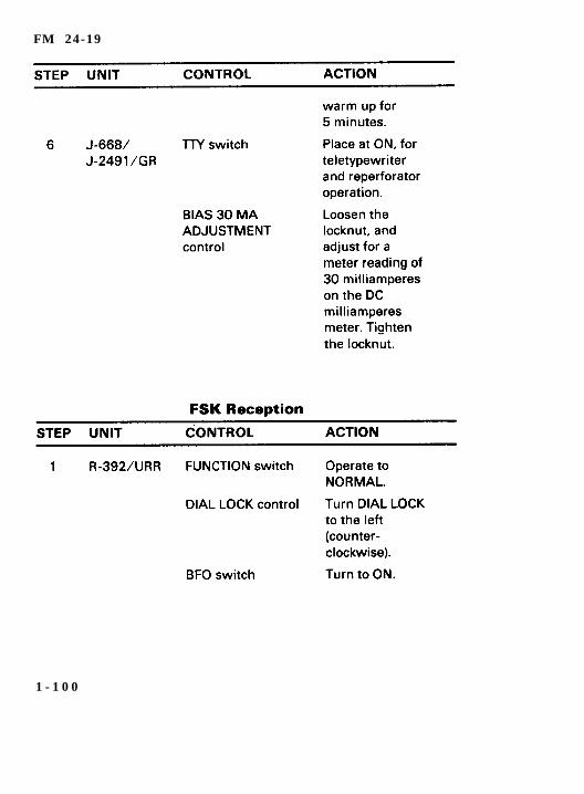
S t a r t i n g P r o c e d u r e s
1 - 9 9
FM 24-19
1 - 1 0 0
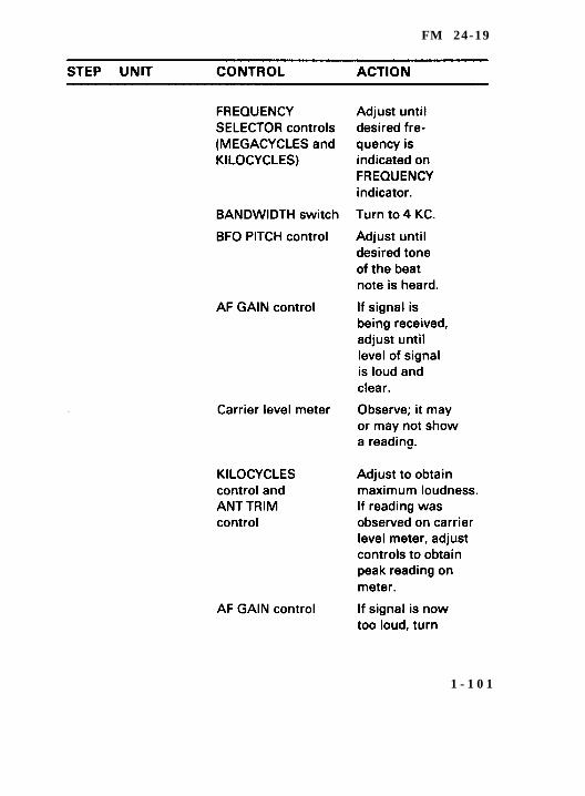
FM 24-19
1 - 1 0 1
FM 24-19
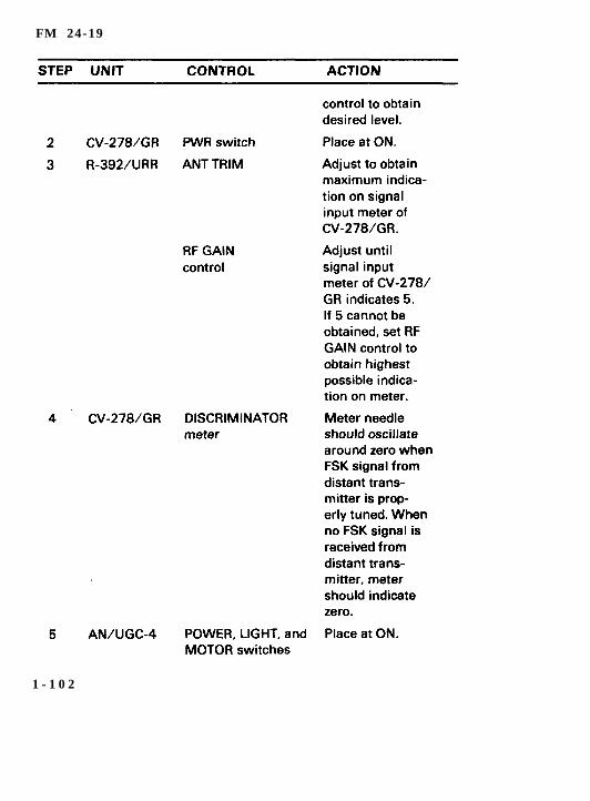
1 - 1 0 2

FM 24-19
1 - 1 0 3
F M 2 4 - 1 9
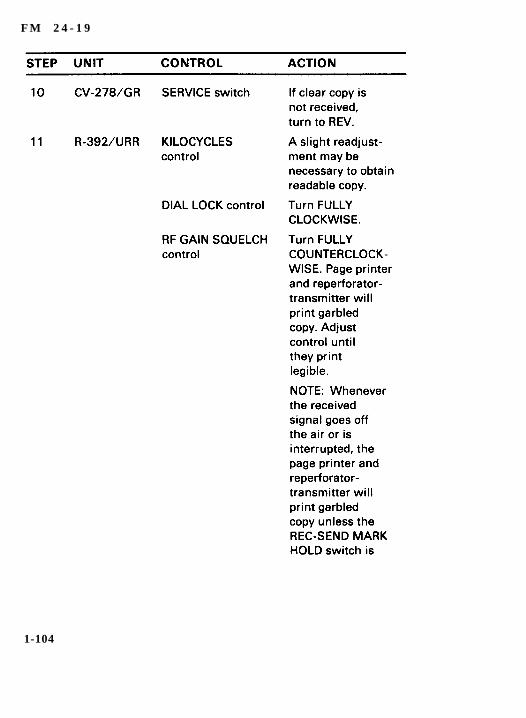
1-104
FM 24-19
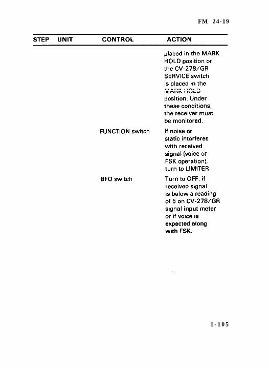
1 - 1 0 5
FM 24-19
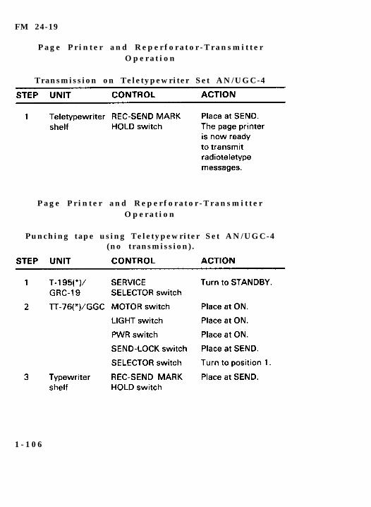
P a g e P r i n t e r a n d R e p e r f o r a t o r - T r a n s m i t t e rO p e r a t i o n
Transmission on Teletypewriter Set AN/UGC-4
P a g e P r i n t e r a n d R e p e r f o r a t o r - T r a n s m i t t e rO p e r a t i o n
Punching tape using Teletypewriter Set AN/UGC-4(no transmission) .
1 - 1 0 6

FM 24-19
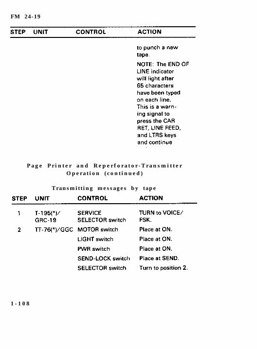
P a g e P r i n t e r a n d R e p e r f o r a t o r - T r a n s m i t t e rO p e r a t i o n ( c o n t i n u e d )
Punching Tape using reperforator- transmitterkeyboard (no transmission) .
1 - 1 0 7
FM 24-19
P a g e P r i n t e r a n d R e p e r f o r a t o r - T r a n s m i t t e rO p e r a t i o n ( c o n t i n u e d )
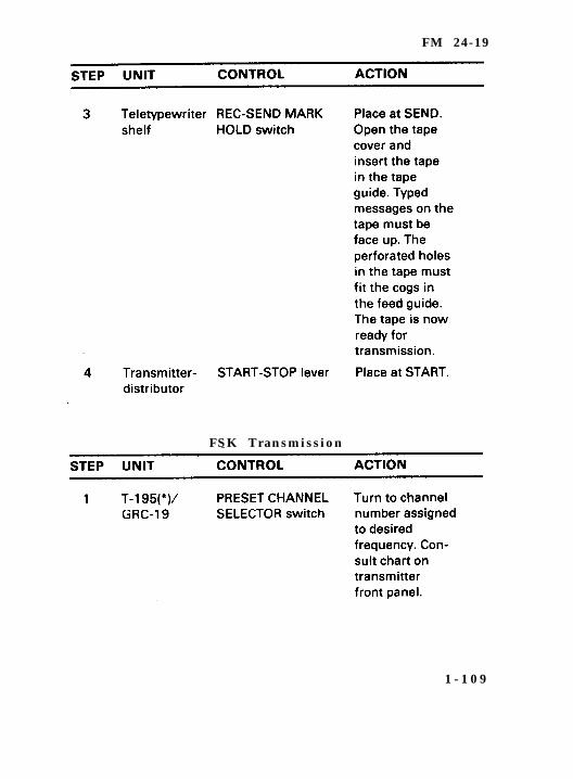
Transmitt ing messages by tape
1 - 1 0 8
FM 24-19
FSK Transmission
1 - 1 0 9

FM 24-19
1 - 1 1 0
FM 24-19
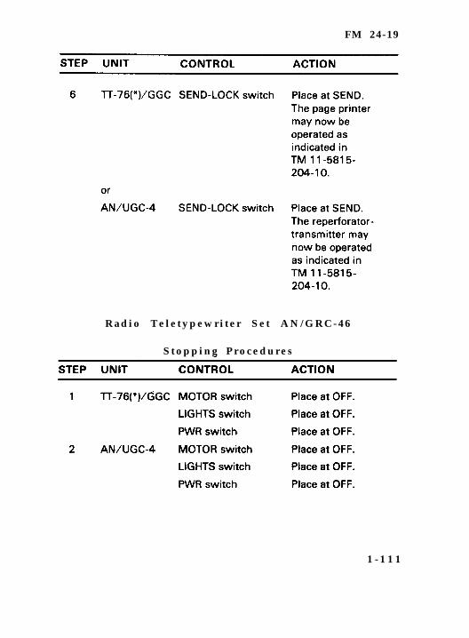
R a d i o T e l e t y p e w r i t e r S e t A N / G R C - 4 6
S t o p p i n g P r o c e d u r e s
1 - 1 1 1
FM 24-19
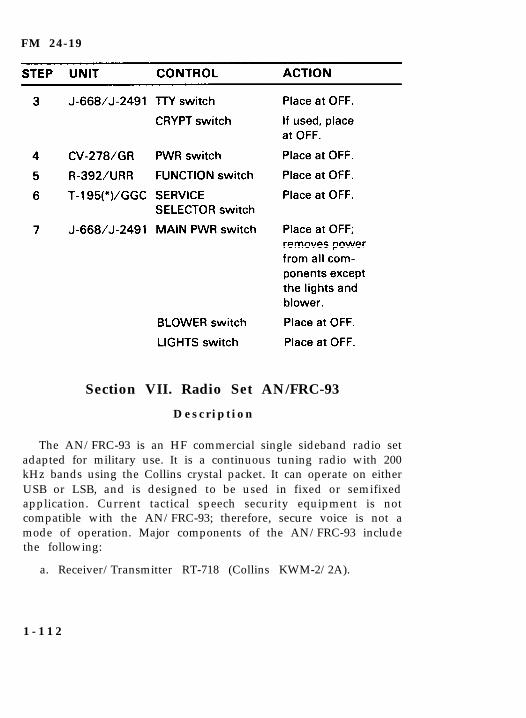
Section VII. Radio Set AN/FRC-93
D e s c r i p t i o n
The AN/FRC-93 is an HF commercial single sideband radio setadapted for military use. It is a continuous tuning radio with 200kHz bands using the Collins crystal packet. It can operate on eitherUSB or LSB, and is designed to be used in fixed or semifixedapplication. Current tactical speech security equipment is notcompatible with the AN/FRC-93; therefore, secure voice is not amode of operation. Major components of the AN/FRC-93 includethe following:
a. Receiver/Transmitter RT-718 (Collins KWM-2/2A).
1 - 1 1 2
FM 24-19
b.
c.
d.
e.
f.
a.
b.
c.
d.
e.
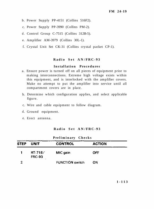
Power Supply PP-4151 (Collins 516F2).
Power Supply PP-3990 (Collins PM-2).
Control Group C-7515 (Collins 312B-5).
Amplifier AM-3979 (Collins 30L-1).
Crystal Unit Set CK-31 (Collins crystal packet CP-1).
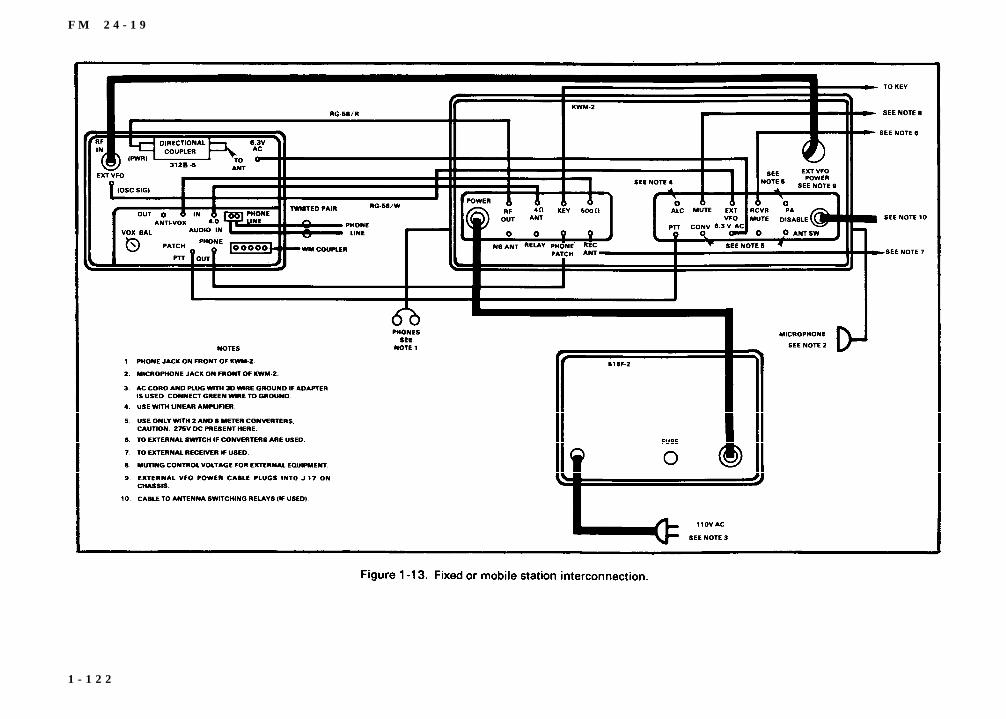
R a d i o S e t A N / F R C - 9 3
Instal lat ion ProceduresEnsure power is turned off on all pieces of equipment prior tomaking interconnections. Extreme high voltage exists withinthis equipment, and is interlocked with the amplifier covers.Make no attempt to put the amplifier into service until allcompartment covers are in place.
Determine which configuration applies, and select applicablefigure.
Wire and cable equipment to follow diagram.
Ground equipment.
Erect antenna.
R a d i o S e t A N / F R C - 9 3
Preliminary Checks
1 - 1 1 3
FM 24-19
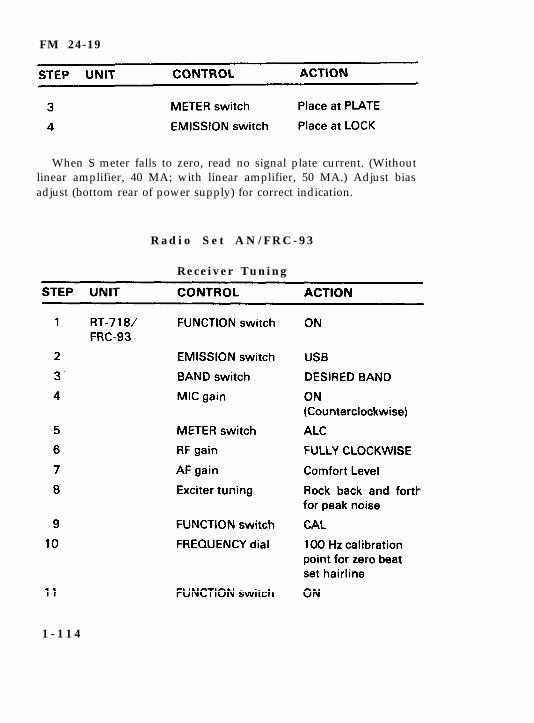
When S meter falls to zero, read no signal plate current. (Withoutlinear amplifier, 40 MA; with linear amplifier, 50 MA.) Adjust biasadjust (bottom rear of power supply) for correct indication.
R a d i o S e t A N / F R C - 9 3
Receiver Tuning
1 - 1 1 4
FM 24-19
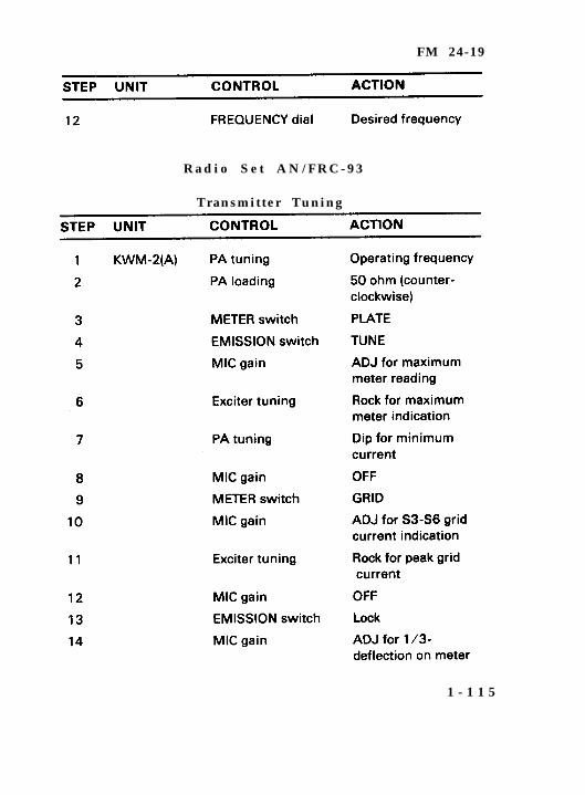
R a d i o S e t A N / F R C - 9 3
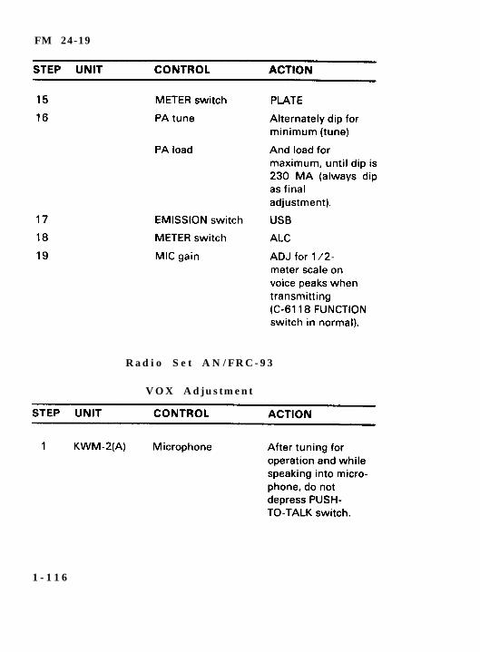
Transmitter Tuning
1 - 1 1 5
FM 24-19
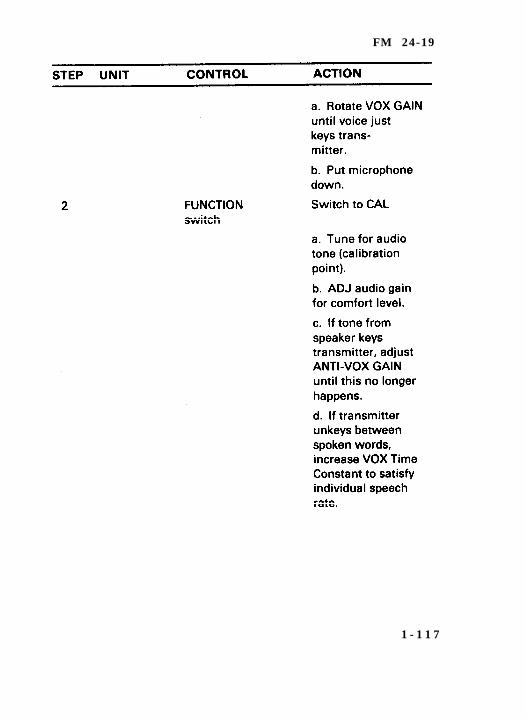
R a d i o S e t A N / F R C - 9 3
VOX Adjustment
1 - 1 1 6
FM 24-19
1 - 1 1 7
FM 24-19
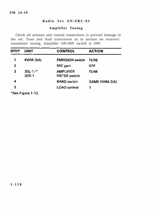
R a d i o S e t A N / F R C - 9 3
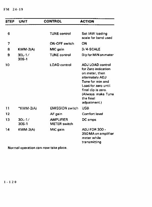
Amplifier Tuning
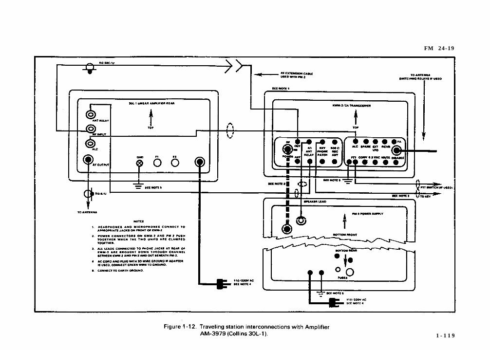
Check all antenna and coaxial connections to prevent damage tothe set. Tune and load transceiver as in section on receiver/transmitter tuning. Amplifier ON-OFF switch is OFF.
1 - 1 1 8
FM 24-19
1 - 1 1 9
F M 2 4 - 1 9
1 - 1 2 0
FM 24-19
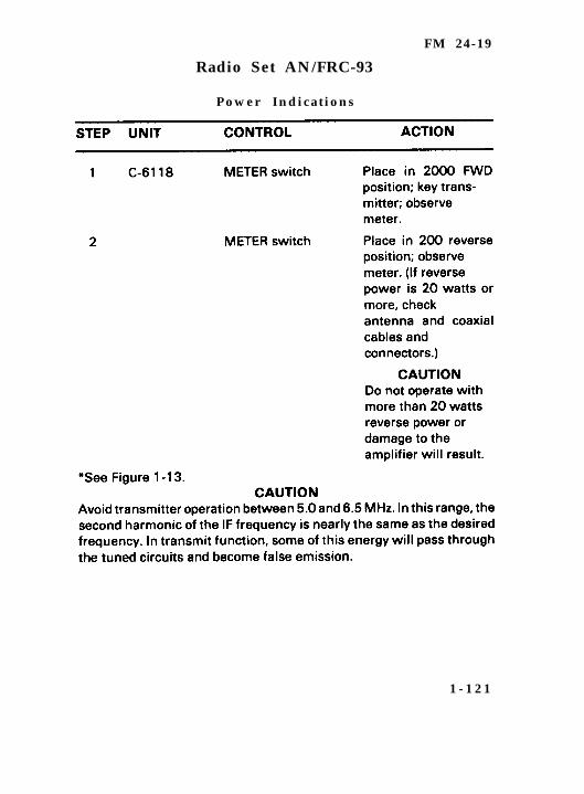
Radio Set AN/FRC-93
Power Indicat ions
1 - 1 2 1
F M 2 4 - 1 9
1 - 1 2 2
FM 24-19
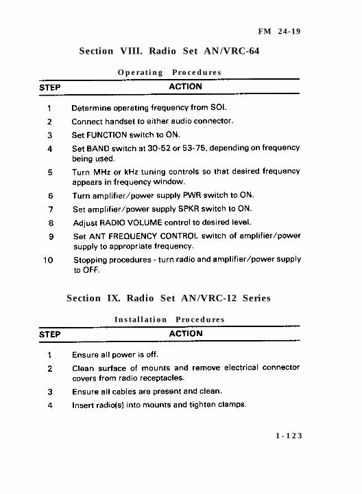
Section VIII. Radio Set AN/VRC-64
Operating Procedures
Section IX. Radio Set AN/VRC-12 Series
Instal lat ion Procedures
1 - 1 2 3
FM 24-19
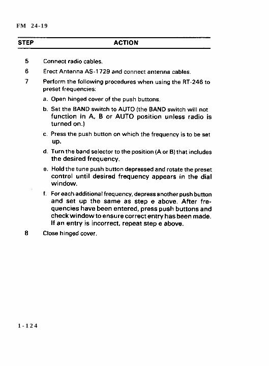
1 - 1 2 4
FM 24-19
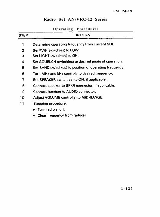
Radio Set AN/VRC-12 Series
Operating Procedures
1 - 1 2 5
FM 24-19
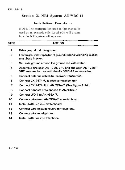
Section X. NRI System AN/VRC-12
Instal lat ion Procedures
NOTE: The configuration used in this manual isused as an example only. Local SOP will dictatehow the NRI system will operate.
1 - 1 2 6
FM 24-19
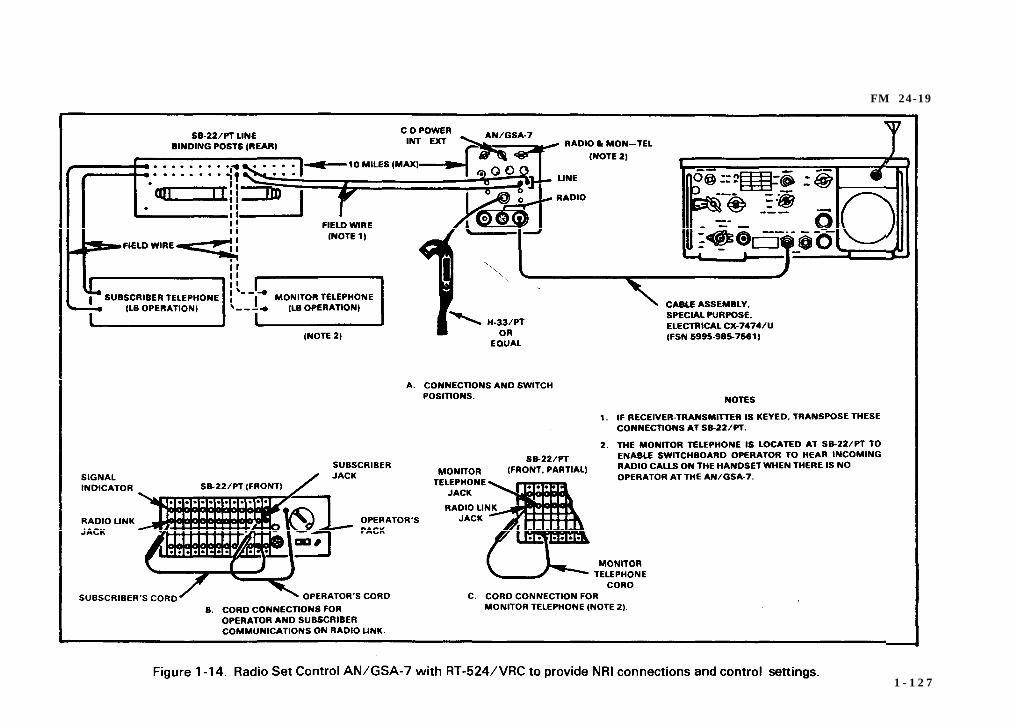
1 - 1 2 7
FM 24-19
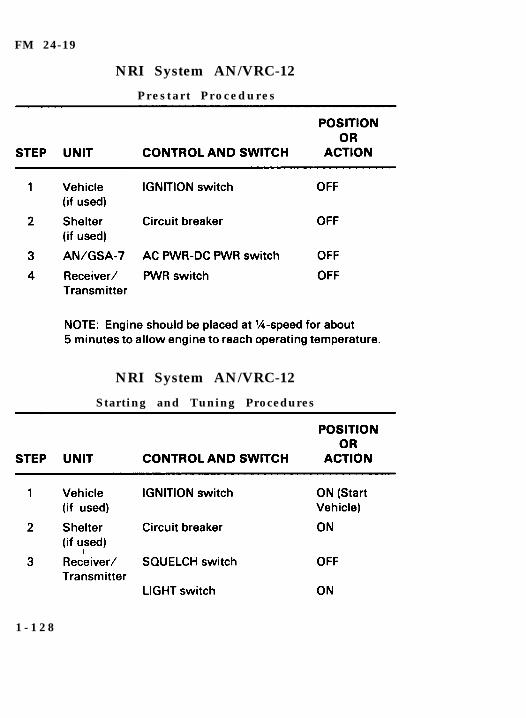
NRI System AN/VRC-12
P r e s t a r t P r o c e d u r e s
NRI System AN/VRC-12
Starting and Tuning Procedures
1 - 1 2 8
FM 24-19
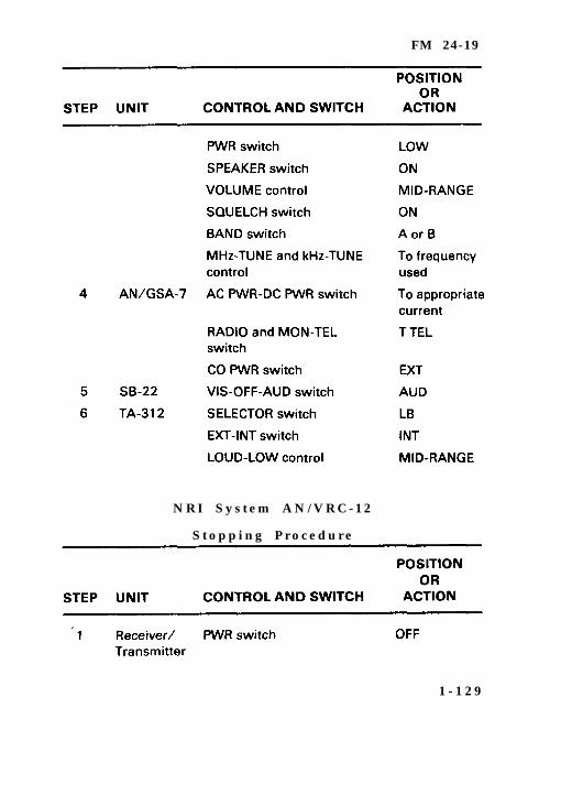
N R I S y s t e m A N / V R C - 1 2
S t o p p i n g P r o c e d u r e
1 - 1 2 9
FM 24-19
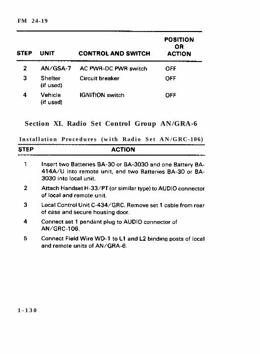
Section XI. Radio Set Control Group AN/GRA-6
Instal lat ion Procedures (with Radio Set AN/GRC-106)
1 - 1 3 0
FM 24-19
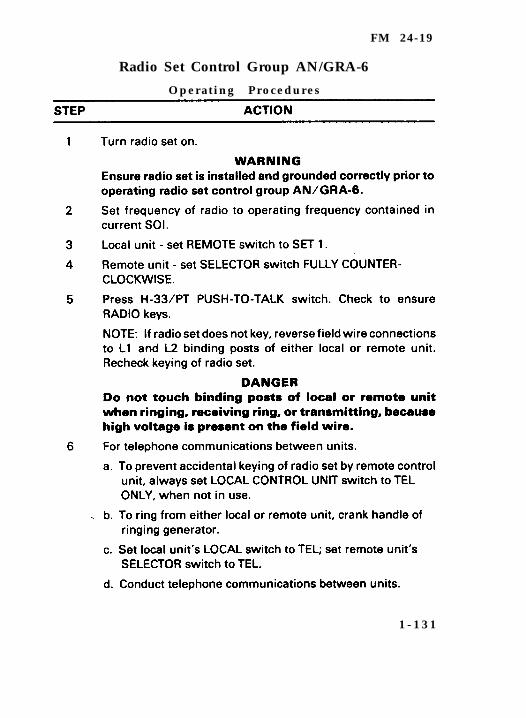
Radio Set Control Group AN/GRA-6
Operating Procedures
1 - 1 3 1
FM 24-19
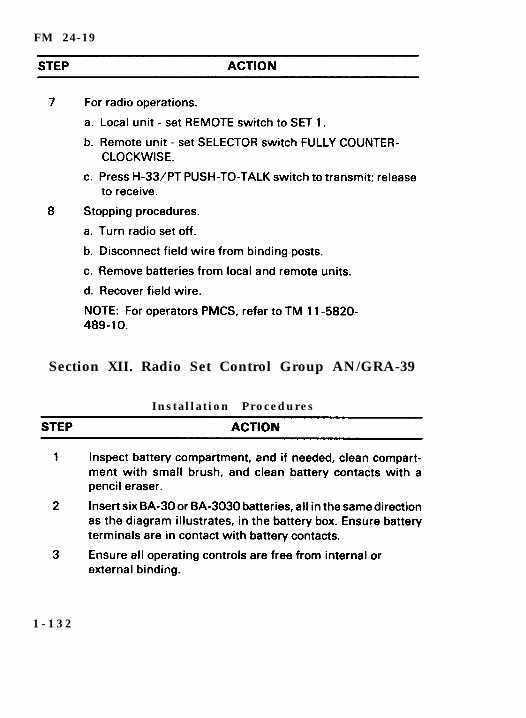
Section XII. Radio Set Control Group AN/GRA-39
Instal lat ion Procedures
1 - 1 3 2
FM 24-19
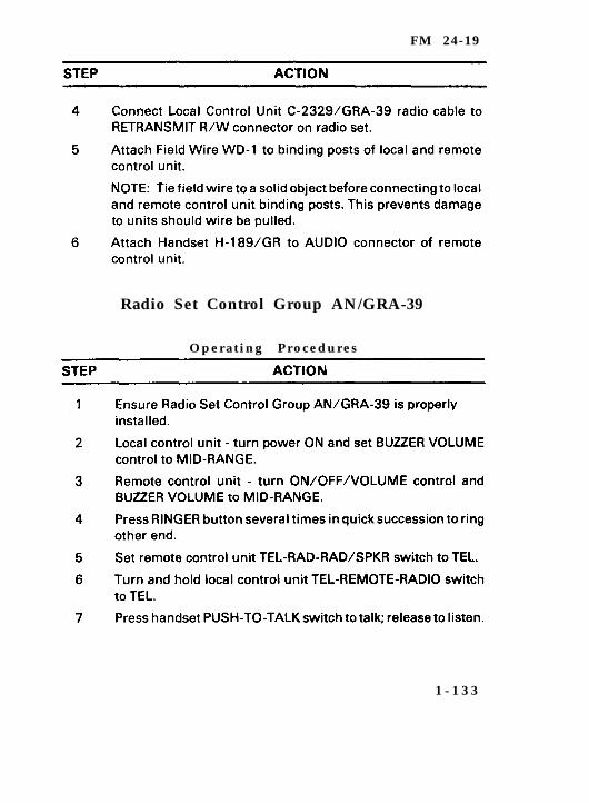
Radio Set Control Group AN/GRA-39
Operating Procedures
1 - 1 3 3
FM 24-19
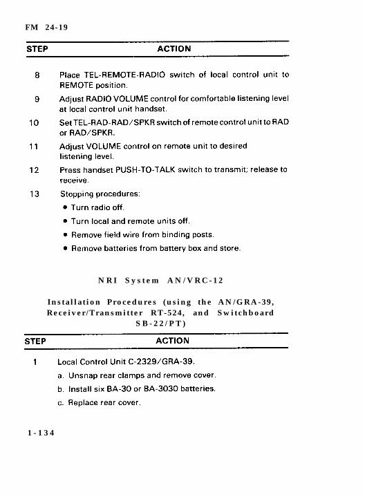
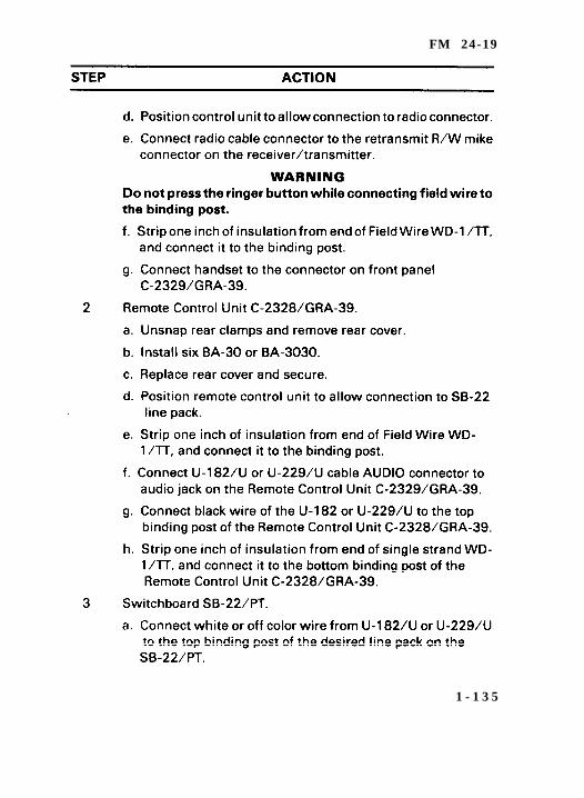
N R I S y s t e m A N / V R C - 1 2
Instal lat ion Procedures (using the AN/GRA-39,Receiver/Transmitter RT-524, and Switchboard
S B - 2 2 / P T )
1 - 1 3 4
FM 24-19
1 - 1 3 5
FM 24-19
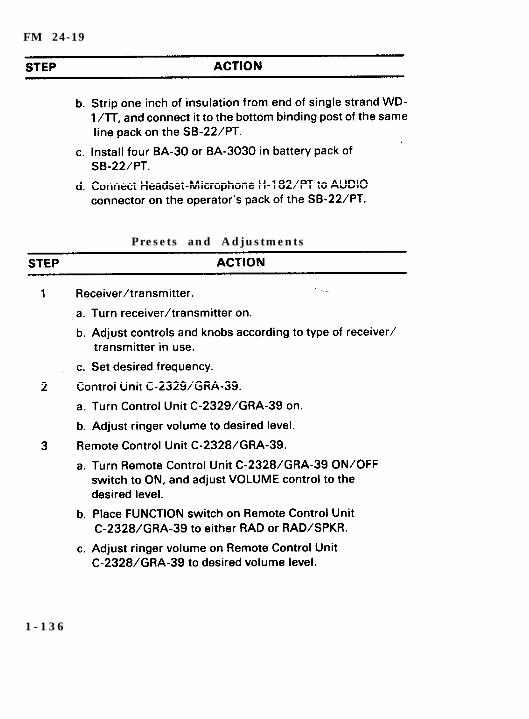
Presets and Adjustments
1 - 1 3 6
FM 24-19
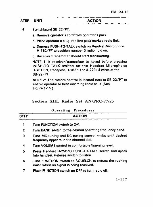
Section XIII. Radio Set AN/PRC-77/25
Operating Procedures
1 - 1 3 7
F M 2 4 - 1 9
1 - 1 3 8
FM 24-19
Section XIV. Radio Set AN/PRC-104A
Instal lat ion and Operating Procedures
a. Transportation and storage. The AN/PRC-104A is an ultralightweight, HF, manpack radio. The radio set and its componentsare contained, transported and stored in Radio Set Case CY-8291/PRC-104 (transit case). The transit case normally should bekept closed. To unpack the equipment, unfasten the four latches andremove the transit case cover. Each of the pieces of equipment fitsinto a molded space. Upon receiving this radio set, ensure theequipment is complete. Inspect the equipment for any shippingdamage.
b. The components must be assembled (installed) for operation.Figure 1-16 shows how the components of the AN/PRC-104A areassembled to make the set operational.
Press the pressure release valve button to equalize pressurebefore unlatching the transit cover. Then unfasten the fourlatches securing the cover to the transit case and remove thecover.
Remove the receiver/transmitter and amplifier/coupler fromthe transit case. Ensure the connectors on the two pieces arecompletely engaged by pressing the two together from the ends.Secure the two by using the quick-connect/disconnect latcheson the front and rear of the amplifier/coupler. Tighten thelatches until snug.
Attach the battery pack to the bottom of the receiver/exciterand the amplifier/coupler. It is critical to ensure the connectorson the battery pack and the amplifier/coupler are lined up. Thisis where the electrical connections are made by the battery.Secure the assembly by using the two quick-disconnect latcheson the battery pack.
1 - 1 3 9
FM 24-19
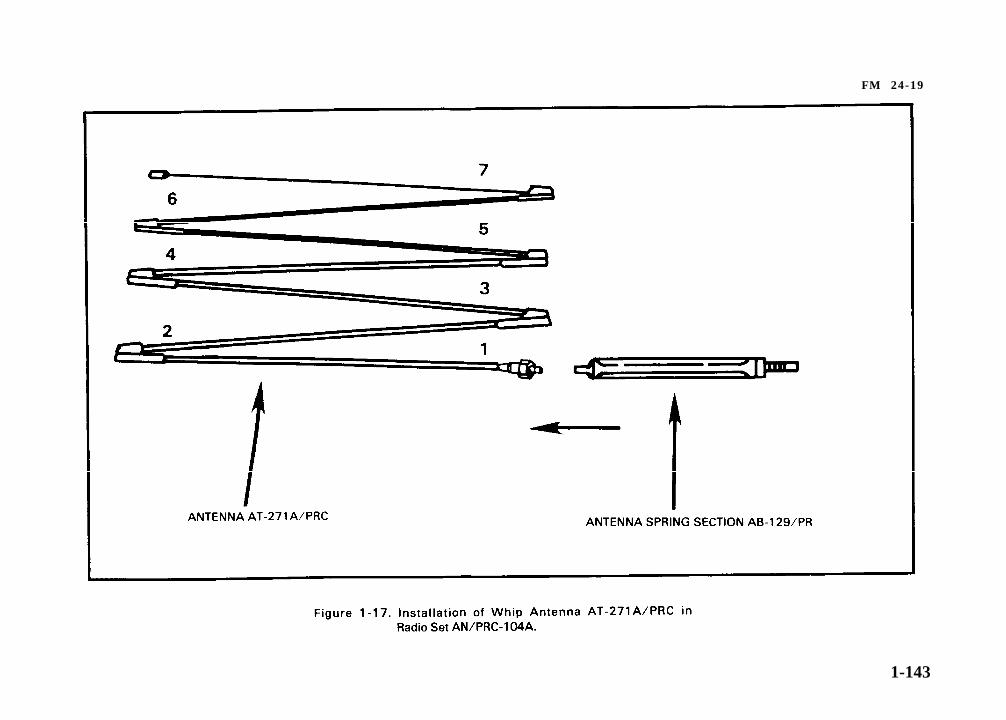
c. The Whip Antenna AT-271A/PRC has seven sections (Figure1-17). Each section fits into the end of a wider section. A stainlesssteel, plastic covered cable (or braided plastic cord), under springtension, is threaded through the sections to keep them together inthe operating condition. When the sections are folded, the cablekeeps them together as a group and prevents the loss of individualsections. Spring tension is provided by a spiral spring in the basesection. Spring section, Antenna Base AT-129/PR (Figure 1-17) isused to keep the antenna stable.
1 - 1 4 0
FM 24-19
Remove antenna shock mount from the transit case.
Screw Antenna Spring Section AB-129/PR into the bottomsection of the whip antenna.
Pull on section 2, 3, 4, 5, 6, and 7. Insert section 2 into section 1.Continue to assemble all sections in this manner.
CAUTIONDo not try to assemble this antenna from the smallest section (7) to thelargest (1). Doing so will put too much strain on the nylon cord inside theantenna and cause it to break. Start assembly from the largest end(1).
Screw the entire assembly into the antenna socket on the radio(Figure 1-16).
Connect a handset to the radio set upper AUDIO connector.
The set is now ready to operate.
1 - 1 4 1

FM 24-19
1 - 1 4 2
FM 24-19
1-143
FM 24-19
Radio Set AN/PRC-104A
Preoperat ional Checks
Radio Set AN/PRC-104A
P r e s e t s
1 - 1 4 4
FM 24-19
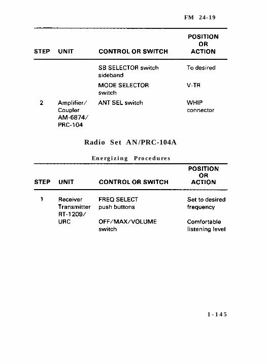
Radio Set AN/PRC-104A
Energizing Procedures
1 - 1 4 5

FM 24-19
R a d i o S e t A N / P R C - 1 0 4 A
Tuning Procedures
R a d i o S e t A N / P R C - 1 0 4 A
T e s t P r o c e d u r e s
When the radio has concluded its tuning procedure, perform anoperational test on the radio. The test procedures are as follows:
Change frequency by at least 1 kHz; then momentarily pressthe handset PTT switch.
Listen for a l-kHz tune tone. (Tuning is brief. It maybe 3 to 12seconds.)
NOTE: Tune tone should terminate within 12 seconds. Thisindicates the automatic antenna tuner is operating normally. Acontinuous, rapid beeping sound in the handset indicates the radiohas failed to tune properly (a tuning fault exists).
Transmit using the handset. Press the PTT switch, andcommunicate with another radio set on the test frequency. Asidetone in the handset earpiece indicates transmission issatisfactory. (For fault tone, refer to the radio troubleshootingprocedure.)
1 - 1 4 6
FM 24-19
Repeat the above procedures for test frequencies spacedthrough the 2 to 30 MHz part of the radio spectrum to test theauto tune feature. Your frequency manager has thesefrequencies.
Se lect a f requency for the t ime s tandard broadcast(multiples of 5 MHz; for example, 5, 10, 15, 20 MHz). For thistest, one frequency may be better than another, depending onthe time of day and station. You may not hear these stationsoutside the United States.
Monitor the time standard broadcast and switch sidebands.Verify no change in the pitch of the audible signals. Thisindicates the frequency accuracy of the radio set is withinspecifications.
Turn the radio off. The test is complete. The radio set is good.
R a d i o S e t A N / P R C - 1 0 4 A
Operat ing Procedures
Turn MODE switch to V-TR.
Turn SIDEBAND switch to USB or LSB (see SOI).
Set frequency to your net operating frequency (see SOI).
Turn ANT SEL switch to WHIP ANTENNA.
Turn VOLUME control to desired listening level. Power isapplied at this time through the VOLUME control.
NOTE: If a clicking sound is heard, the battery is a weak (20volts or less) and needs to be replaced.
Momentarily press and release the handset PTT switch.
1 - 1 4 7

FM 24-19
Listen for l-kHz tune tone. Tuning is brief (3 to 12 seconds).
NOTE: Tune tone should terminate within 12 seconds. Thisindicates the radio is tuned and ready for operation. Acontinuous, rapid beeping in the handset indicates the radiohas failed to tune properly (a tune fault exists). Refer to thetroubleshooting procedures or to organization maintenance.
To communicate with the AN/PRC-104A, use the handset asfollows:
Press the PTT switch, transmit to another station, and releasethe PTT switch to hear (receive) the other station.
Press to transmit, and release to listen.
Listen for sidetone in the handset earpiece. Sidetone indicatesyou are transmitting.
R a d i o S e t A N / P R C - 1 0 4 A
Modes of Operation
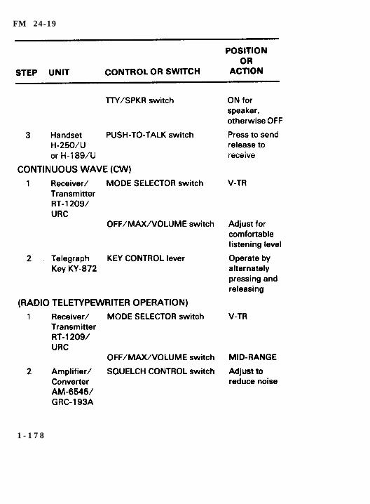
a. Voice.
Turn MODE SELECTOR switch to V-TR.
Adjust OFF/MAX/VOLUME switch to comfortable listeninglevel.
Press handset PTT switch and talk, release it to receive.
b. CW.
Turn MODE SELECTOR switch to V-TR.
Adjust OFF/MAX/VOLUME switch to comfortable listeninglevel.
Connect Leg Key KY-872 to upper AUDIO connector.
1 - 1 4 8

F M 2 4 - 1 9
1 - 1 4 9
FM 24-19
e. The Radio Set Control Group AN/GRA-39 controls the remoteoperation of the tactical radio set. It includes the RemoteControl Unit C-2328/GRA-39, the Local Control Unit C-2329/GRA-39, Handset H-189/GR, and carrying Bag CW-598/GRA-39 (a bag and a carrying sling).
NOTE: The AN/GRA-39 is not issued with the AN/PRC-104A.
Disconnect the H-250/U handset control cable from the upperAUDIO connector on the receiver/transmitter.
Connect the control cable of the local unit, the C-2329/GRA-39,to the upper AUDIO connector of the receiver/transmitter.
Connect the H-250/U control cable to the AUDIO connector onLocal Control Unit C-2329/GRA-39.
The remote unit C-2328/GRA-39 may be up to two miles fromthe radio set. It is connected to the line terminals of the localunit by 600 ohm wire that is connected to the line terminals ofthe remote unit.
NOTE: Any wire may be connected to any line terminal on thelocal and remote control units.
Connect the control cable of the Handset H-189/GR, suppliedwith the AN/GRA-39, to the audio jack of the Remote ControlUnit C-2328/GRA-39.
f. Voice communications can be received and transmittedthrough the radio set and can be controlled either locally or atthe option of the operators.
g. The remote unit has a loudspeaker to monitor all received radiosignals. The volume is controlled by the VOLUME controlknob on the receiver/transmitter.
1 - 1 5 0
FM 24-19
R a d i o S e t A N / P R C - 1 0 4 A
S t o p p i n g P r o c e d u r e s
Turn the OFF/MAX/VOLUME switch to OFF.
R a d i o S e t A N / P R C - 1 0 4 A
Disassemble and Transport Procedures
To disassemble and transport the radio set—
Turn power off.
Remove the antenna and antenna shock mount (base) from theradio set.
Remove the antenna shock mount (base) from the antenna andplace the base in the space provided in the transit case.
Start at the tip (top end), fold the seven-section antenna, andplace it in the transit case.
Remove the handset and place it in the transit case.
Remove the battery pack from the receiver/transmitter-amplifier/coupler. Put the battery pack in the transit case.Remove batteries from the battery case and transport themseparately.
WARNINGOnly battery packs that are not activatad may be placed in thetransit casa. An activated battery pack must be transportedand stored separately.
Place the receiver/transmitter-amplifier/coupler combinationinto the transit case.
Replace the transit case cover, and fasten the four latches.
NOTE: The radio set is now ready for transport or storage.
1-151
FM 24-19
R a d i o S e t A N / P R C - 1 0 4 A
Operator Daily and Weekly PMCS
a. The operator must perform daily and weekly PMCS.Although it is not specifically a part of daily or weekly PMCS,the radio set must be cleaned. PMCS keeps the radio setoperational; keeping the radio set clean is just as important.
b. Clean the radio set when needed by—
Removing dirt, dust, grease, or other debris from externalsurfaces using a cloth or brush moistened in clear water. Drythe equipment with a soft, lint-free cloth.
Cleaning any dust or dirt from the connectors and pins with asoft-bristled brush.
c. Check for corrosion or fungus on the radio set when preparing itfor operation or when you are operating it. During PMCS,separate the three units if they are installed. Also, check theexterior surface controls and connectors for signs of corrosionor fungus. Remove corrosion or fungus with a cloth and/orbrush moistened in cleaning solvent. Repaint any surfaces thatneed painting.
d. The following pages discuss the daily and weekly PMCS. Theoperator performs daily PMCS when the equipment isoperated. The operator performs weekly PMCS when theequipment is not operated daily. However, daily PMCS also isperformed whenever weekly PMCS is performed. Whenperforming PMCS, report items that are broken or damagedbeyond repair to the next higher maintenance level. Anydeficiencies you cannot correct must be reported onDA Form 2404.
1-152
FM 24-19
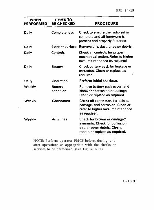
NOTE: Perform operator PMCS before, during, andafter operations as appropriate with the checks orservices to be performed. (See Figure 1-19.)
1 - 1 5 3
FM 24-19
1 - 1 5 4
FM 24-19
Section XV. Radio Set AN/GRC-213
D e s c r i p t i o n
a. The AN/GRC-213 is a lightweight (50 pounds), low power(20-watt) output, HF radio set capable of short- to long-rangecommunications. It uses the same receiver-transmitter (RT-1209/URC) as the AN/PRC-104A, but has no battery pack. Itoperates from the vehicle power supply using amplifier/power supply AM-7152/GRC-213 to filter and condition thevehicle power for the radio set. The amplifier/power supplyalso amplifies and squelches (cut out the rushing noise) theaudio output to drive an external speaker and providesconnection for an AIN/VIC-l.
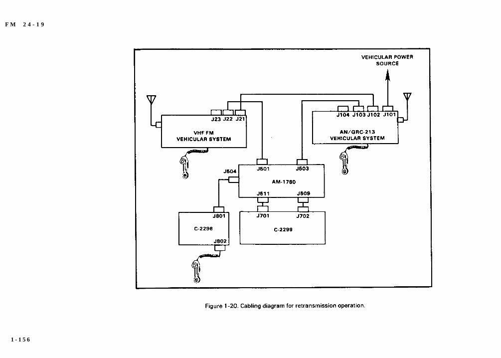
b. The radio set can be mounted in a wheeled or tracked vehicle,or installed in a fixed location, such as a building or tent.When installed in a fixed location, a power supply capable ofproviding 24 to 32 volts DC (26.5 VDC nominal) must be used(for example, Generator Set 3 kW, 29 VDC, or Battery ChargerPP-1451/G or similar power supply). In vehicles equippedwith the Intercommunications Set (Intercom) AN/VIC-1,automatic retransmission is possible from any singlesideband radio, such as the AN/GRC-213, to any FM radio,such as the AN/VRC-12 series (Figure 1-20).
1 - 1 5 5
F M 2 4 - 1 9
.
1 - 1 5 6
FM 24-19
R a d i o S e t A N / G R C - 2 1 3
Instal lat ion Procedures
a. Before operating Radio Set AN/GRC-213, check to make sureit is properly installed in the mount. Ensure it is grounded andhas an antenna connected to it.
b. Connections for grounding the radio set to the mount are atthe rear of the radio set. Quick connect ground straps connectthe components together and ground the radio set to themount. Make sure the ground straps are connected properly toprovide a proper ground. Do not depend on the metal to metalcontact between the components to ground the radio set.When operating from a stationary position, connect a groundstrap between the vehicle and a ground rod that has beendriven into the ground. This will prevent electrical shockwhen touching the vehicle. (Refer to TC 11-6 for propergrounding techniques.)
c. The AN/GRC-213 uses any antenna designed for HFcommunications. The most common are the 15-foot whipantenna, the half-wave (doublet) antenna, the quarter-waveantenna and the NVIS antenna. Refer to Chapter 3 for a list ofthe characteristics of these antennas.
d. Before operating your radio, ensure an antenna is installedand connected to the radio set. Operating a radio with noantenna may cause serious damage to the equipment. Whenusing the whip antenna, be sure the correct number ofsections are installed (normally five each, three-foot sections).
1 - 1 5 7
FM 24-19
R a d i o S e t A N / G R C - 2 1 3
Operat ing Procedures
Turn MODE switch to V-TR.
Turn SIDEBAND switch to USB or LSB (see SOI).
Set FREQUENCY to your net operating frequency (see SOI).
Turn ANT SEL switch to MIDDLE (BNC connector) position.
Turn VOLUME control to desired listening level. Power isapplied at this time through the VOLUME control.
NOTE: A clicking sound indicates low vehicle battery voltage (20volts or less). The vehicle should be running during operation of theAN/GRC-213 to prevent draining the vehicle’s battery. Beforestarting the vehicle, be sure the radio is off to prevent damage to theradio.
Momentarily press and release the handset PTT switch.
Listen for a 1-kHz tune tone. Tuning is brief. It may be 3 to 12seconds.
NOTE: Tune tone should terminate within 12 seconds. Thisindicates the radio is tuned and ready for operation. A continuous,rapid beeping in the handset indicates the radio has failed to tuneproperly (a tune fault exists). Refer to the troubleshooting proce-dures or to organization maintenance.
To communicate with the AN/GRC-213–
Press the handset PTT switch, and speak into the mouthpieceof the handset. Release the PTT switch to listen (receive) to theother station.
Press to transmit, and release to listen.
Listen for sidetone in the handset earpiece. Sidetone indicatesyou are transmitting.
1 - 1 5 8
F M 2 4 - 1 9
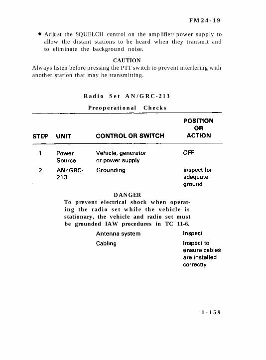
Adjust the SQUELCH control on the amplifier/power supply toallow the distant stations to be heard when they transmit andto eliminate the background noise.
CAUTIONAlways listen before pressing the PTT switch to prevent interfering withanother station that may be transmitting.
R a d i o S e t A N / G R C - 2 1 3
Preoperat ional Checks
DANGERTo prevent electrical shock when operat-ing the radio set while the vehicle isstationary, the vehicle and radio set mustbe grounded IAW procedures in TC 11-6.
1 - 1 5 9
FM 24-19
R a d i o S e t A N / G R C - 2 1 3
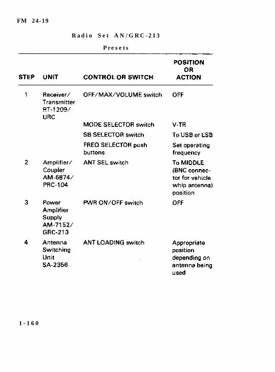
P r e s e t s
1 - 1 6 0
FM 24-19
R a d i o S e t A N / G R C - 2 1 3
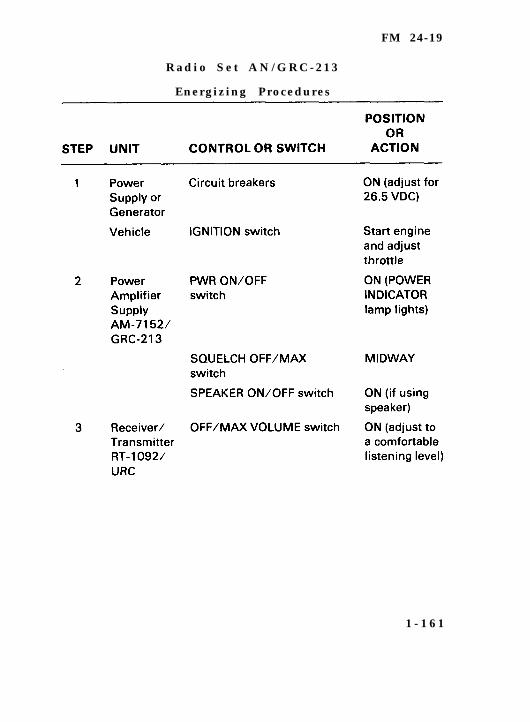
Energizing Procedures
1 - 1 6 1
FM 24-19
R a d i o S e t A N / G R C - 2 1 3
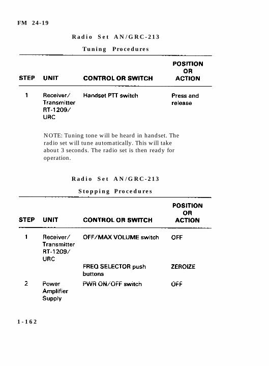
Tuning Procedures
NOTE: Tuning tone will be heard in handset. Theradio set will tune automatically. This will takeabout 3 seconds. The radio set is then ready foroperation.
R a d i o S e t A N / G R C - 2 1 3
S t o p p i n g P r o c e d u r e s
1 - 1 6 2
FM 24-19
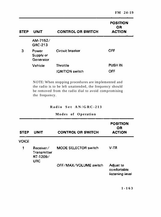
NOTE: When stopping procedures are implemented andthe radio is to be left unattended, the frequency shouldbe removed from the radio dial to avoid compromisingthe frequency.
R a d i o S e t A N / G R C - 2 1 3
Modes of Operation
1 - 1 6 3

FM 24-19
NOTE: The procedures for remote operation of Radio SetAN/GRC-213 are the same as for Radio Set AN/PRC-104A. See section on remote operation for Radio SetAN/PRC-104A in this manual.
1 - 1 6 4

FM 24-19
R a d i o S e t A N / G R C - 2 1 3
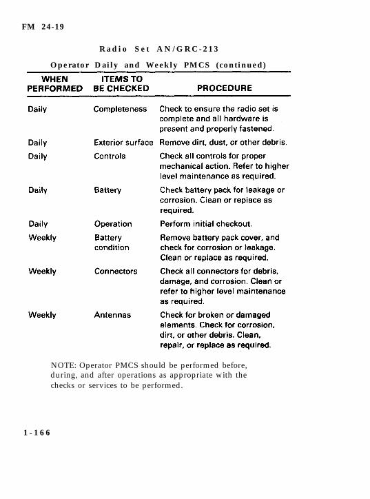
Operator Daily and Weekly PMCS
a. The operator must perform daily and weekly PMCS. Although itis not specifically a part of daily or weekly PMCS, the radio set mustbe cleaned. PMCS keeps the radio set operational; keeping the radioset clean is just as important.
b. Clean the radio set when needed by—
Removing dirt, dust, grease, or other debris from externalsurfaces using a cloth or brush moistened in clear water. Drythe equipment with a soft, lint-free cloth.
Cleaning any dust or dirt from the connectors and pins with asoft-bristled brush.
c. Check for corrosion or fungus on the radio set when preparing itfor operation or when you are operating it. During PMCS, separatethe three units if they are installed. Also, check the exterior surfacecontrols and connectors for signs of corrosion or fungus. Removecorrosion or fungus with a cloth and/or brush moistened incleaning solvent. Repaint any surfaces that need painting.
d. The following pages discuss the daily and weekly PMCS. Theoperator performs daily PMCS when the equipment is operated.The operator performs weekly PMCS when the equipment is notoperated daily. However, daily PMCS also is performed wheneverweekly PMCS is performed. When performing PMCS, report itemsthat are broken or damaged beyond repair to the next higher main-tenance level. Any deficiencies you cannot correct must be reportedon DA Form 2404.
1 - 1 6 5
FM 24-19
R a d i o S e t A N / G R C - 2 1 3
Operator Daily and Weekly PMCS (continued)
NOTE: Operator PMCS should be performed before,during, and after operations as appropriate with thechecks or services to be performed.
1 - 1 6 6
FM 24-19
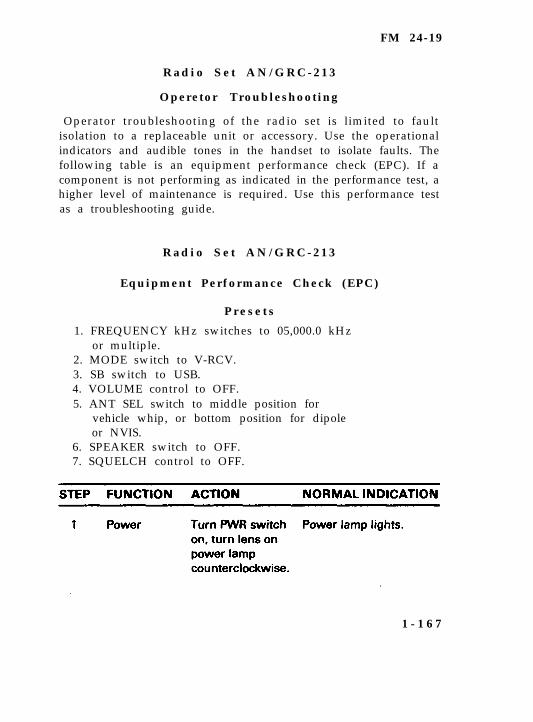
R a d i o S e t A N / G R C - 2 1 3
Operetor Troubleshooting
Operator troubleshooting of the radio set is limited to faultisolation to a replaceable unit or accessory. Use the operationalindicators and audible tones in the handset to isolate faults. Thefollowing table is an equipment performance check (EPC). If acomponent is not performing as indicated in the performance test, ahigher level of maintenance is required. Use this performance testas a troubleshooting guide.
R a d i o S e t A N / G R C - 2 1 3
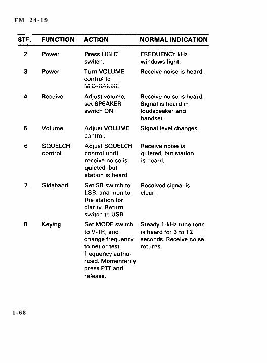
Equipment Performance Check (EPC)
P r e s e t s
1. FREQUENCY kHz switches to 05,000.0 kHzor multiple.
2. MODE switch to V-RCV.3. SB switch to USB.4. VOLUME control to OFF.5. ANT SEL switch to middle position for
vehicle whip, or bottom position for dipoleor NVIS.
6. SPEAKER switch to OFF.7. SQUELCH control to OFF.
1 - 1 6 7
F M 2 4 - 1 9
1 - 6 8
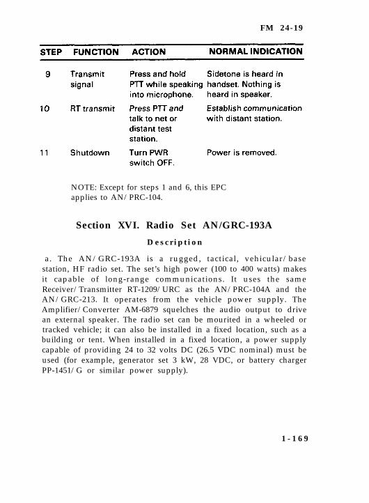
FM 24-19
NOTE: Except for steps 1 and 6, this EPCapplies to AN/PRC-104.
Section XVI. Radio Set AN/GRC-193A
D e s c r i p t i o n
a. The AN/GRC-193A is a rugged, tactical, vehicular/basestation, HF radio set. The set’s high power (100 to 400 watts) makesit capable of long-range communications. It uses the sameReceiver/Transmitter RT-1209/URC as the AN/PRC-104A and theAN/GRC-213. It operates from the vehicle power supply. TheAmplifier/Converter AM-6879 squelches the audio output to drivean external speaker. The radio set can be mourited in a wheeled ortracked vehicle; it can also be installed in a fixed location, such as abuilding or tent. When installed in a fixed location, a power supplycapable of providing 24 to 32 volts DC (26.5 VDC nominal) must beused (for example, generator set 3 kW, 28 VDC, or battery chargerPP-1451/G or similar power supply).
1 - 1 6 9
FM 24-19
b. For the most part, the technical characteristics of the radio setare the same as the AN/PRC-104A and the AN/GRC-213. However,the AN/GRC-193A has an additional component, Amplifier/Converter AM-6879/GRC-193A. This component makes it capableof radio teletypewriter operations. Additional equipment not issuedwith the AN/GRC-193A (for example, AN/UGC-74(*) and TSEC/KG-84A) is needed for radio teletypewriter operations. A tacticalantenna remoting kit enhances the operational flexibility of theAN/GRC-193A. The kit allows remoting of the Antenna CouplerCU-2064/193A and the antenna 200 feet from the radio set. Formore information, see TM 11-5820-924-13.
R a d i o S e t A N / G R C - 1 9 3 A
Instal lat ion Procedures
a. Before operating Radio Set AN/GRC-193A, ensure it is properlyinstalled in the mount. Make sure it is grounded and has anantenna connected to the radio.
b. Attach the ground strap to one of the ground terminals on frontof the antenna coupler. The other end is connected to the mount.Install a ground rod and attach one end of a ground strap to theremaining terminal on the antenna coupler and the other end to theground rod. This will prevent electrical shock when touching thevehicle. (See TC 11-6 for proper grounding techniques.)
c. Before operating the AN/GRC-193A, be sure an antenna hasbeen connected to the radio set. The AN/GRC-193Ais issued with a15-foot whip antenna and two 50 ohm antenna kits (DoubletAntenna AN/GRA-50 and NVIS AS-2259/GR Antenna).
DANGERThere are 10,000 volts at the antanna tarminal J4 when ueingtha whip antenna or J3 terminal when using the 50 ohmantenna. Do not remove during operation. Extreme cautionmust be taken to ensure thase terminals are at least 6 inchesfrom nearby objects such as cables, guy wires, brackets orground leads.
1 - 1 7 0
FM 24-19
R a d i o S e t A N / G R C - 1 9 3 A
Operat ing Procedures
Make preoperational checks.
Make control presets.
Turn VOLUME control to desired listening level. Power isapplied at this time through the VOLUME control.
NOTE: A clicking sound indicates low vehicle battery voltage(20 volts or less). Start the vehicle before powering up the radioset. Leave it running while operating the AN/GRC-193A toprevent draining the vehicle’s battery power.
Connect a handset to the UPPER audio receptacle of the RT-1209/URC or the AM-6545/GRC-193A.
Momentarily press and release the handset PTT switch.
Listen for a 1-kHz tune tone. Tuning is brief. It may be 3 to 12seconds.
NOTE: Tune tone should terminate within 12 seconds. Thisindicates the radio is tuned and ready for operation. Acontinuous, rapid beeping in the handset indicates failure ofthe radio to properly tune (a tune fault exists). Refer to thetroubleshooting procedures or to organization maintenance.
To communicate with the AN/GRC-193A–
Press the handset PTT switch, and speak into the mouthpieceof the handset. Release the PTT switch to listen (receive) theother station.
Press to transmit, and release to listen.
Listen for sidetone in the handset earpiece. Sidetone indicatesyou are transmitting.
1 - 1 7 1
FM 24-19
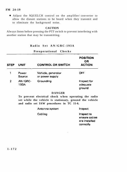
Adjust the SQUELCH control on the amplifier/converter toallow the distant stations to be heard when they transmit andto eliminate the background noise.
CAUTIONAlways listen before pressing the PTT switch to prevent interfering withanother station that may be transmitting.
R a d i o S e t A N / G R C - 1 9 3 A
Preoperat ional Checks
DANGERTo prevent electrical shock when operating the radioset while the vehicle is stationary, ground the vehicleand radio set IAW procedures in TC 11-6.
1 - 1 7 2
FM 24-19
R a d i o S e t A N / G R C - 1 9 3 A
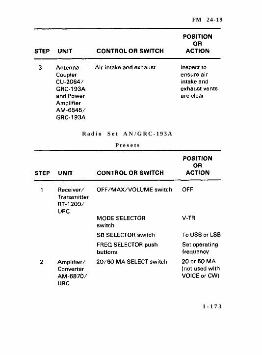
P r e s e t s
1 - 1 7 3
FM 24-19
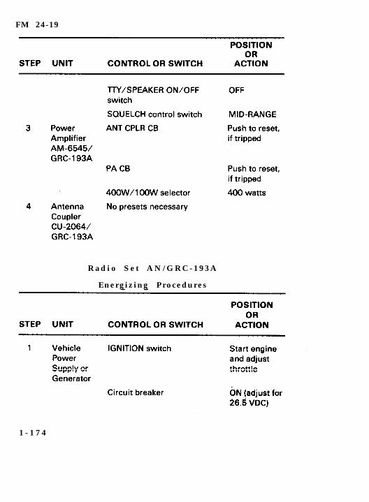
R a d i o S e t A N / G R C - 1 9 3 A
Energizing Procedures
1 - 1 7 4
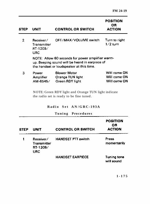
FM 24-19
NOTE: Green RDY light and Orange TUN light indicatethe radio set is ready to be fine tuned.
R a d i o S e t A N / G R C - 1 9 3 A
Tuning Procedures
1 - 1 7 5
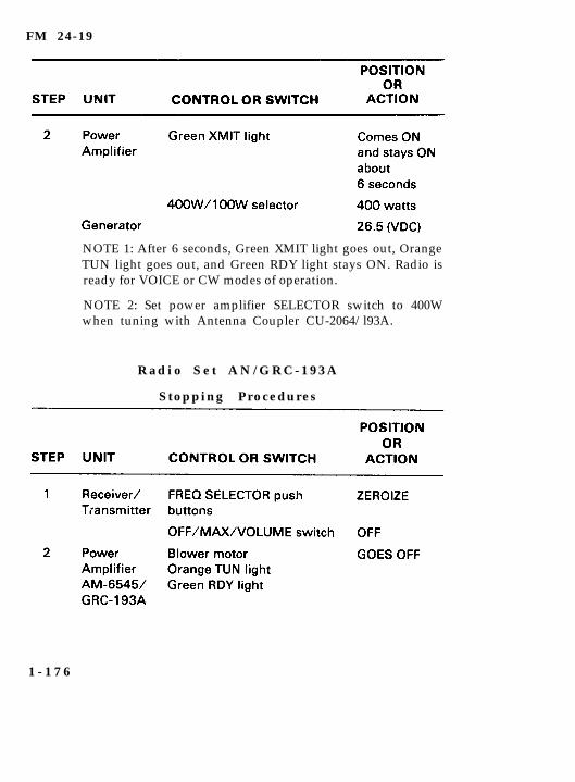
FM 24-19
NOTE 1: After 6 seconds, Green XMIT light goes out, OrangeTUN light goes out, and Green RDY light stays ON. Radio isready for VOICE or CW modes of operation.
NOTE 2: Set power amplifier SELECTOR switch to 400Wwhen tuning with Antenna Coupler CU-2064/l93A.
R a d i o S e t A N / G R C - 1 9 3 A
Stopping Procedures
1 - 1 7 6
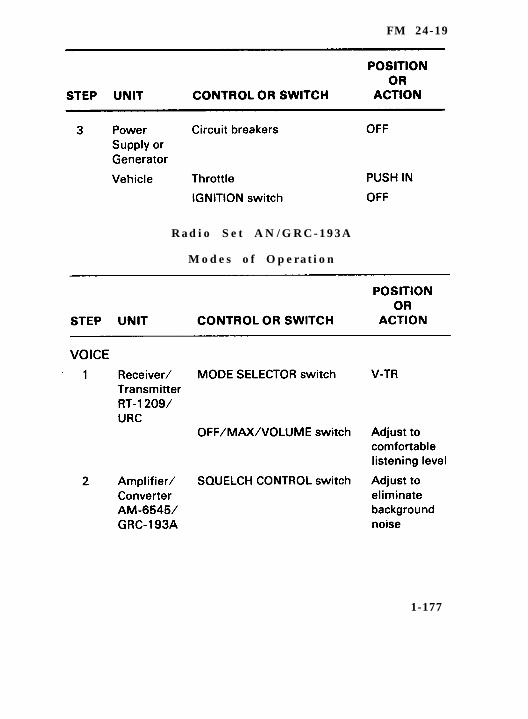
FM 24-19
R a d i o S e t A N / G R C - 1 9 3 A
M o d e s o f O p e r a t i o n
1-177
FM 24-19
1 - 1 7 8

FM 24-19
NOTE: The procedures for remote operation of Radio SetAN/GRC-l 93Aarethe same as for RadioSetsAN/PRC-104A and AN/GRC-213.
(RADIO SILENCE)
NOTE: The procedures for radio silence are the same forall the radios. The MODE switch on the receiver/transmitter is placed in the RCV position. Do not breakradio silence without proper authority.
R a d i o S e t A N / G R C - 1 9 3 A
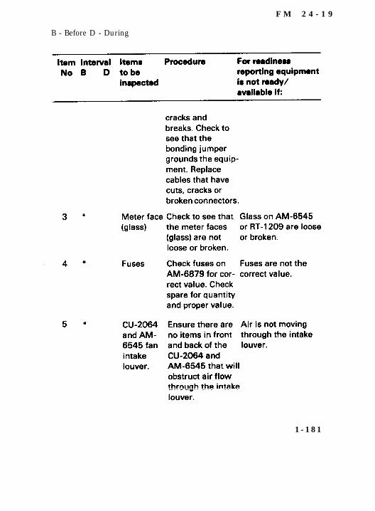
Preventive Maintanance Checks and Sarvices (PMCS)
a. PMCS of the AN/GRC-193A are required to keep the equipmentin good operating condition. They include before operation, duringoperation and after operation checks. If the equipment is operateddaily, perform maintenance each day. If the equipment is
1 - 1 7 9

FM 24-19
maintained in a STANDBY condition (not used), perform PMCSweekly.
DANGERBefore you operate, always keep in mind the cautions andwarnings. This equipment can seriously injure or kill if it is notoperated safely and properly.
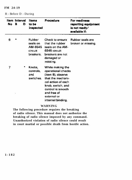
b. The PMCS charts do not list routine checks, such as equipmentinventory, cleaning components, checking for frayed and damagedcables, replacing items not in use, checking for loose hardware andsafety wires, and corrosion or receptacles and connectors. Do thesethings any time they need to be done. This is a matter of goodpreventive maintenance.
B - Before D - During
1 - 1 8 0
F M 2 4 - 1 9
B - Before D - During
1 - 1 8 1
FM 24-19
B - Before D - During
WARNINGThe following procedure requires the breakingof radio silence. This manual does not authorize thebreaking of radio silence imposed by any command.Unauthorized violation of radio silence could resultin court martial or possible death from hostile action.
1 - 1 8 2
FM 24-19
B - Before D - During
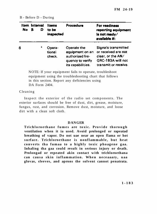
NOTE: If your equipment fails to operate, troubleshootequipment using the troubleshooting chart that followsin this section. Report any deficiencies usingDA Form 2404.
Cleaning
Inspect the exterior of the radio set components. Theexterior surfaces should be free of dust, dirt, grease, moisture,fungus, rust, and corrosion. Remove dust, moisture, and loosedirt with a clean soft cloth.
DANGERTrichloroethane fumes are toxic . Provide thoroughventilation when it ia used. Avoid prolonged or rapeatadbreathing of vapor. Do not uae near an open flama or hotsurface. Trichloroethane is nonflammable, but heatconverts tha fumaa to a highly toxic phoagene gaa.Inhaling tha gaa could result in serious injury or death.Prolongad or repeated akin contact with trichloroethanacan causa skin inflammation. When neceaaary, uaaglovas, sleeves, and aprons the solvent cannot penatrata.
1 - 1 8 3
FM 24-19
Remove grease, fungus, and ground-in dirt from the equipmentcovers. Use a dampened cloth (but not wet) with trichloroethane.
Remove dust or dirt from plugs and jacks with a brush.
CAUTIONDo not press the glass of the meter on the AM-6545 or the RT-1209when cleaning.
Clean the meter, front panels, and control knobs. Use a soft cleancloth. If dirt is difficult to remove, dampen the cloth with water.Mild soap may be used for more effective cleaning.
R a d i o S e t A N / G R C - 1 9 3 A
Operator Troubleshooting
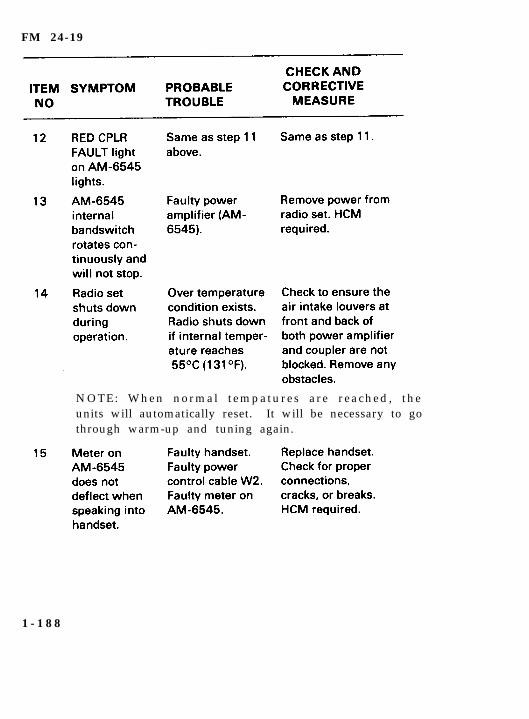
Troubleshooting of this equipment is based upon the operationalcheck in the daily operator PMCS. To troubleshoot the equipment,perform an operational check. Proceed through this check until anabnormal condition or result is observed. When an abnormalcondition or result is observed, turn to the troubleshooting proce-dure on the following pages and determine if there is a similarcondition in the symptom column. If the corrective measuresindicated do not correct the trouble, a higher category of mainte-nance is required. It is assumed the Amplifier/Converter AM-6879front panel fuse has been checked by the operator, and the vehiculargenerating system or external power source is in working order.These items are not listed in the check and corrective measurecolumn of the troubleshooting chart.
1 - 1 8 4
FM 24-19
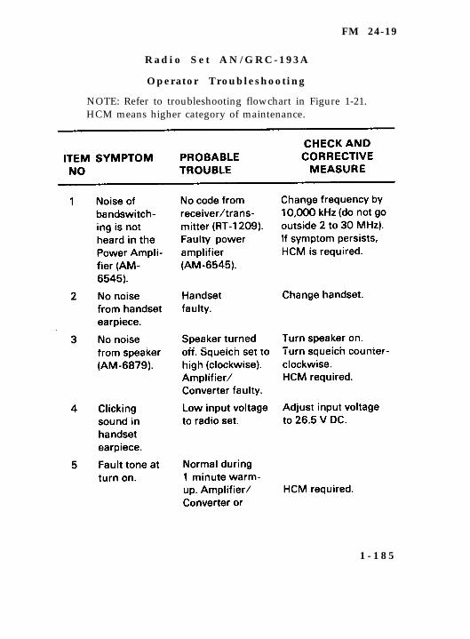
R a d i o S e t A N / G R C - 1 9 3 A
Operator Troubleshooting
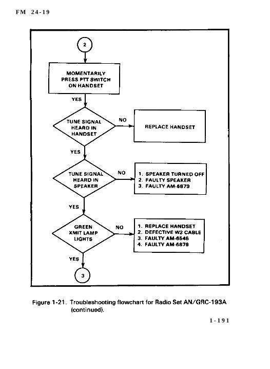
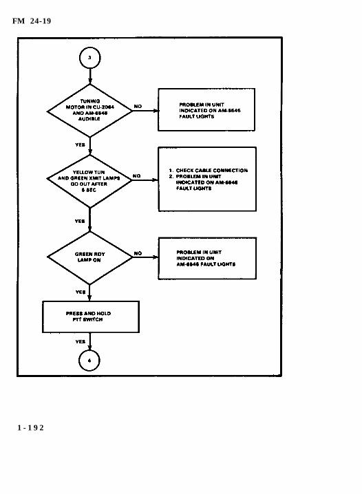
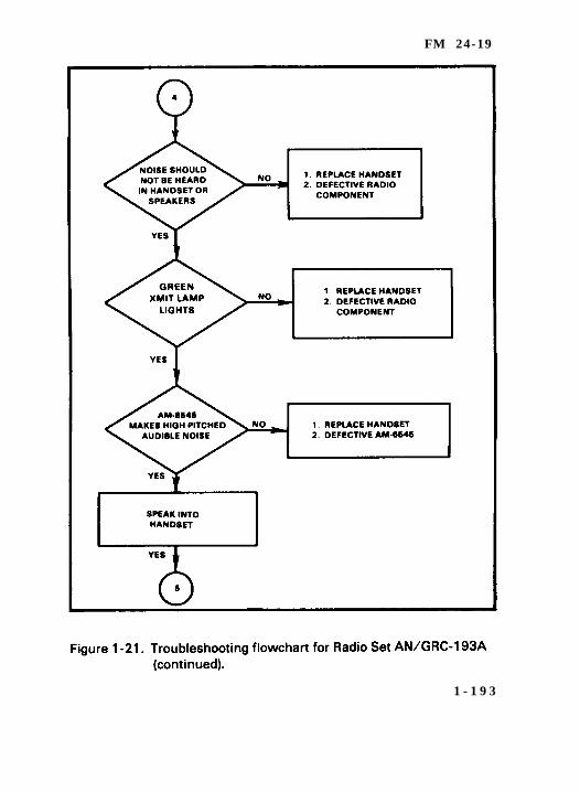
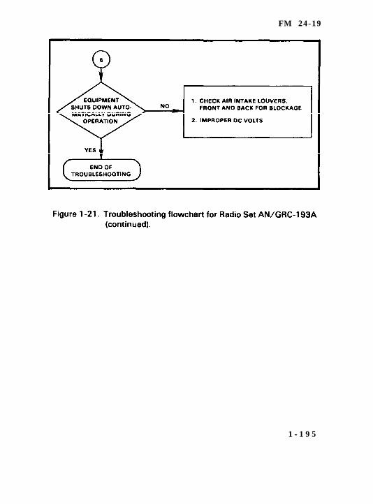
NOTE: Refer to troubleshooting flowchart in Figure 1-21.HCM means higher category of maintenance.
1 - 1 8 5
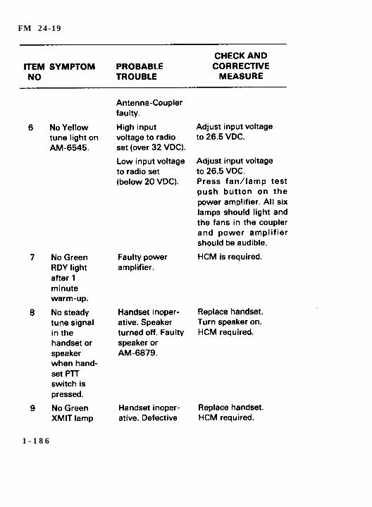
FM 24-19
1 - 1 8 6
F M 2 4 - 1 9
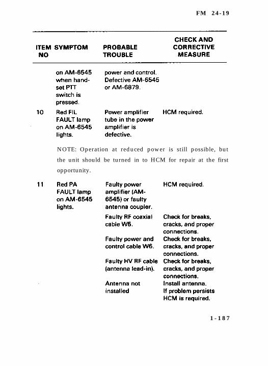
NOTE: Operation at reduced power is still possible, but
the unit should be turned in to HCM for repair at the first
opportunity.
1 - 1 8 7
FM 24-19
NOTE: When normal tempatures are reached, theunits will automatically reset. It will be necessary to gothrough warm-up and tuning again.
1 - 1 8 8

FM 24-19
1 - 1 8 9

FM 24-19
1 - 1 9 0
F M 2 4 - 1 9
1 - 1 9 1
FM 24-19
1 - 1 9 2
FM 24-19
1 - 1 9 3

FM 24-19
1 - 1 9 4
FM 24-19
1 - 1 9 5
FM 24-19
Section XVII. Single-Channel Ground and AirborneRadio System (SINCGARS) and AN/TSC-124
(SCOTT)
SINCGARS
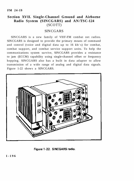
SINCGARS is a new family of VHF-FM combat net radios.SINCGARS is designed to provide the primary means of commandand control (voice and digital data up to 16 kb/s) for combat,combat support, and combat service support units. To help thecommunications system survive, SINCGARS provides a resistanceto jam (ECCM) capability using single-channel offset or frequencyhopping. SINCGARS also has a built in data adapter to allowtransmission of a wide range of analog and digital data signals.Figure 1-22 shows a SINCGARS.
1 - 1 9 6
FM 24-19
A N / T S C - 1 2 4 ( S C O T T )
a. The AN/TSC-124 is a single-channel, tactical satellite com-munications terminal. It provides highly survivable, antijam andhigh altitude electromagnetic pulse-protected (HAEMP) satellitecommunications for nonstrategic forces, contingency units, specialoperations units, and theater forces. It will provide critical commandand control communications and replace existing terrestrial com-munications nets. The AN/TSC-124 will survive when the enemyhas degraded or destroyed other communications, although voicecommunications will be possible. (See Figure 1-23.)
b. The AN/TSC-124–
Consists of the terminal mounted in S-250 shelter, prime mover,and trailer-mounted power generator. Backup power isprovided by the prime mover.
Accepts up to four datdvoice inputs from UCID 2500 feet awayfrom the terminal.
Operates in both DAMA and TMDA modes.
Provides electronic ECCM capability.
Can accept over-the-air rekeying of TRANSEC devices.
1 - 1 9 7

FM 24-19
1 - 1 9 8
FM 24-19
Regency Net System
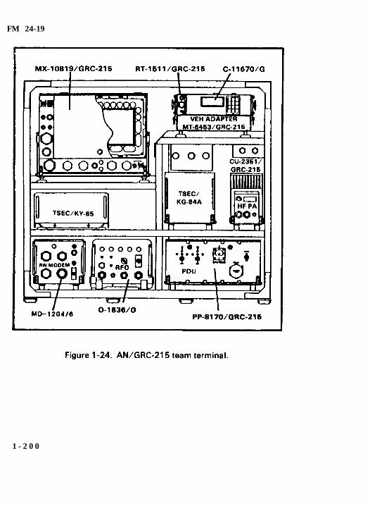
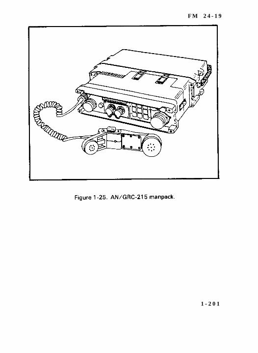
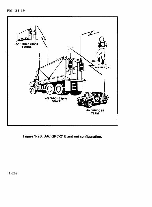
a. The Regency Net System provides survivable HF radiocommand, control, and communications which pass messagesaccurately and rapidly for US Commander-in-Chief, Europe andPacific and internal unit communications within their majorsubordinate commands. The Regency Net System includes the forceterminal which is a multichannel terminal housed in a S-280 shelterand a team terminal which is a single-channel terminal mounted ina ¼-ton vehicle. For the purpose of this manual, only team terminal(Figures 1-24 through 1-26) will be discussed.
b. The AN/GRC-215 team terminal—
Consists of a single channel 100-watt HF transceiver whichis vehicular mountable or manportable.
Provides secure data and voice communications to assignedforce terminals.
Is compatible with force terminals in all modes exceptradioteletype.
Utilizes three microprocessors at data receipt ports tocontrol regency net connectivity, provides radio control,processes messages, and isolates faults.
Has printer port for intirface with either a force terminalthermal printer or the AN/UGC-144 control terminal.
Operates on the move or at halt utilizing 12/24 V DC vehiclepower.
Possesses active ECCM.
Is interoperable with currently fielded single-channel HFradios.
1 - 1 9 9
FM 24-19
1 - 2 0 0
F M 2 4 - 1 9
1 - 2 0 1
FM 24-19
1-202
FM 24-19
Chapter 2Generator Sets
Section I. Generator Set 10 kW (PU-619)
Instal lat ion Procedures
WARNING
Wheels must be blocked, brakes set, and rear lag prop downin support position before attempting to roll up the tarpaulinand before starting to set up or assemble the equipmentfor operation.
CAUTION
It is extremely important to have free air circulation around thegenerator sets at all times. Inadequate ventilation is a majorcause of damage to the equipment.
2 - 1
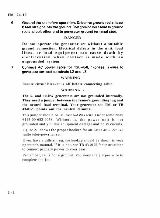
FM 24-19
DANGER
Do not operate the generator set without a suitableground connection. Electrical defects in the unit, loadl i n e s , o r l o a d e q u i p m e n t c a n c a u s e d e a t h b ye l e c t r o c u t i o n w h e n c o n t a c t i s m a d e w i t h a nungrounded system.
WARNING 1
Ensure circuit breaker is off before connecting cable.
WARNING 2
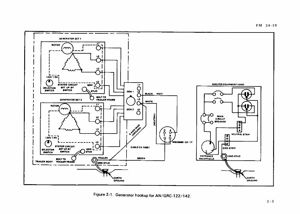
The 5- and 10-kW generators are not grounded internally.They need a jumper between the frame’s grounding lug andthe neutral load terminal. Your generator set TM or TB43-0125 points out the neutral terminal.
This jumper should be at least 6-AWG wire. Order some NSN6145-00-652-9058. Without it, the power unit is notgrounded and you risk equipment damage and noisy circuits.
Figure 2-1 shows the proper hookup for an AN/GRC-122/142radio teletypewriter set.
If you have a different rig, the hookup should be shown in youroperator’s manual. If it is not, see TB 43-0125 for instructionsto connect primary power to your gear.
Remember, L0 is not a ground. You need the jumper wire tocomplete the job.
2 - 2
F M 2 4 - 1 9
2 - 3
FM 24-19
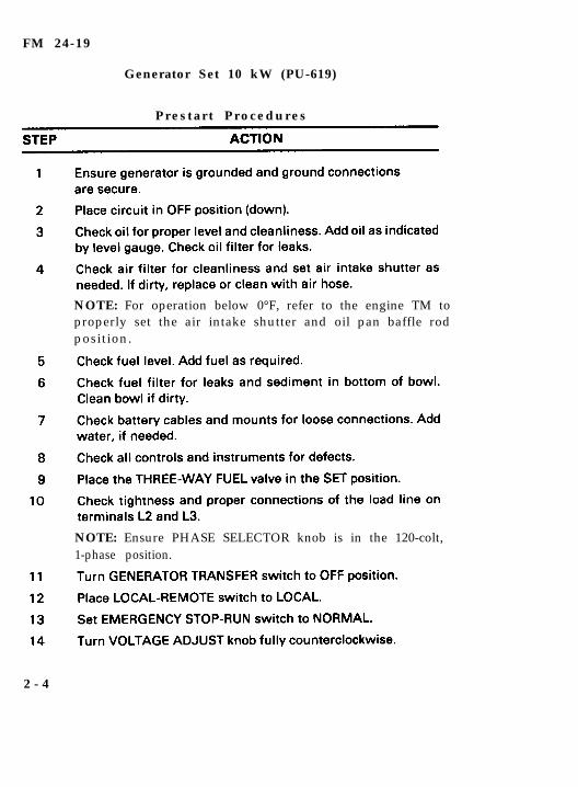
Generator Set 10 kW (PU-619)
P r e s t a r t P r o c e d u r e s
NOTE: For operation below 0°F, refer to the engine TM toproperly set the air intake shutter and oil pan baffle rodposition.
NOTE: Ensure PHASE SELECTOR knob is in the 120-colt,1-phase position.
2 - 4
FM 24-19
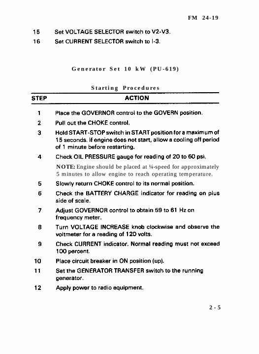
G e n e r a t o r S e t 1 0 k W ( P U - 6 1 9 )
S t a r t i n g P r o c e d u r e s
NOTE: Engine should be placed at ¼-speed for approximately5 minutes to allow engine to reach operating temperature.
2 - 5
FM 24-19
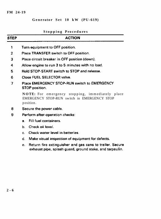
Generator Set 10 kW (PU-619)
S t o p p i n g P r o c e d u r e s
NOTE: For emergency stopping, immediately placeEMERGENCY STOP-RUN switch in EMERGENCY STOPposition.
2 - 6
FM 24-19
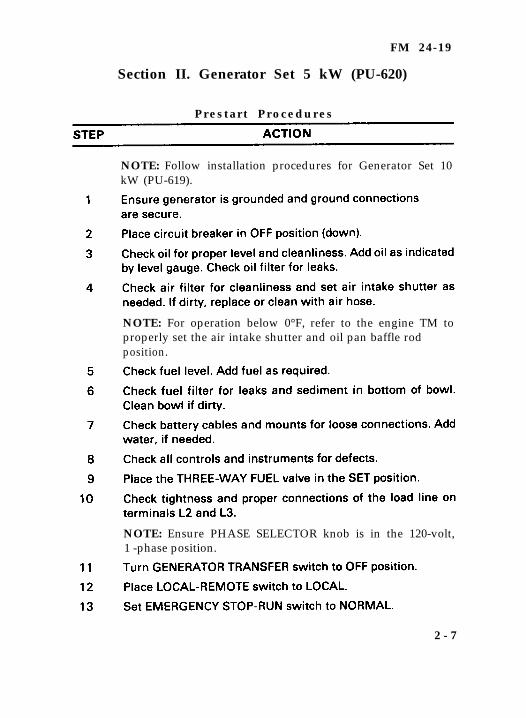
Section II. Generator Set 5 kW (PU-620)
P r e s t a r t P r o c e d u r e s
NOTE: Follow installation procedures for Generator Set 10kW (PU-619).
NOTE: For operation below 0°F, refer to the engine TM toproperly set the air intake shutter and oil pan baffle rodposition.
NOTE: Ensure PHASE SELECTOR knob is in the 120-volt,1 -phase position.
2 - 7
FM 24-19
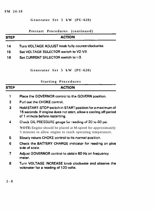
Generator Set 5 kW (PU-620)
Prestart Procedures (continued)
Generator Set 5 kW (PU-620)
S t a r t i n g P r o c e d u r e s
2 - 8
NOTE: Engine should be placed at M-speed for approximately5 minutes to allow engine to reach operating temperature.
FM 24-19
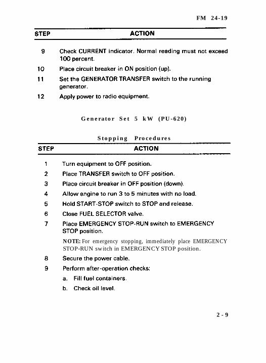
Generator Set 5 kW (PU-620)
Stopping Procedures
NOTE: For emergency stopping, immediately place EMERGENCYSTOP-RUN switch in EMERGENCY STOP position.
2 - 9
FM 24-19
Section III. Generator Set 3 kW (MEP-026A)
Instal lat ion Procedures
WARNING
Wheels must be blocked, brakes set, and rear leg prop downin support position before attempting to roll up the tarpaulinand before starting to set up or assemble the equipmentfor operation.
2 - 1 0
FM 24-19
CAUTION
It is extremely important to have free air circulation around thegenerator sets at all times. Inadequate ventilation is a majorcause of damage to the equipment.
DANGER
Do not operate the generator set without a suitableground connection. Electrical defects in the unit, loadl i n e s , o r l o a d e q u i p m e n t c a n c a u s e d e a t h b ye l e c t r o c u t i o n w h e n c o n t a c t i s m a d e w i t h a nungrounded system.
G e n e r a t o r S e t 3 k W ( M E P - 0 2 6 A )
P r e s t a r t P r o c e d u r e s
2 - 1 1
FM 24-19
G e n e r a t o r S e t 3 k W ( M E P - 0 2 6 A )
Electrical Start ing Procedures
2 - 1 2
FM 24-19
G e n e r a t o r S e t 3 k W ( M E P - 0 2 6 A )
Manual Start ing Procedures
2 - 1 3
FM 24-19
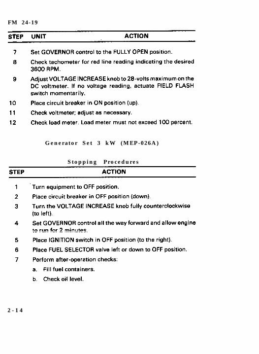
Generator Set 3 kW (MEP-026A)
Stopping Procedures
2 - 1 4

FM 24-19
2 - 1 5
FM 24-19
Chapter 3
Antennas
One of the most important considerations when operating aradio is the type of antenna to be used. For good communicationswith a radio operating in the HF range (2.000 kHz to 29.999 MHz),you must consider the—
Type of antenna.
Operating frequency.
Terrain around the radio site.
Time of day.
Location of and distance between radios.
Atmospheric conditions.
The operator can sometimes control the first four or five factors. Theantenna and frequency are the most important considerationsunder his control. Both should be selected to suit the distancebetween the radios and the propagation characteristics. The opera-tor will most likely have two or three different frequencies assignedfor the operation or exercise. These will be found in the SOI underthe net in which he is operating.
Section I. Antenna Selection
a. The field environment, tactical situation, and distancebetween radio sites determine the type of antenna used. If the radioset is used while on the move, the whip antenna supplied with theequipment is normally used. The whip antenna, using the groundwave, is satisfactory for most short-range missions.
3 - 0
F M 2 4 - 1 9
b. If the tactical situation permits, a simple half-wave dipoleantenna (doublet) or the NVIS antenna is used to extend the rangeof the radio by using the skip phenomenon. Skip means the radiowaves are bounced off the ionosphere and back to earth givingcoverage of 300 miles or more. Figure 3-1 shows the ground waveand sky wave using the skip phenomenon. The NVIS can be used atfrequencies above 12 MHz but automatic tuning of the radio(AN/PRC-104A and/or AN/GRC-213) may not be possible at allfrequencies.
c. When using an antenna with directional characteristics,orient the antenna so that it is most sensitive in the direction of theother station(s). Figure 3-2 shows the radiation pattern of theantennas.
d. Standard and optional antennas that can be used with IHFRsare listed below.
WHIP ANTENNA Omnidirectional (360-degreeradiation pattern).
AS-2259/GR(NVIS)
Easily and quickly assembledand erected.
Lightweight and easy to carry.
Limited range (10 miles or less)over land.
Omnidirectional.
Requires large clear area (80feet square) for proper erection.
Long range (0 to 300 miles).
3 - 1
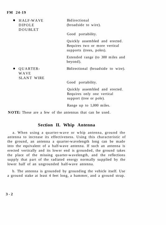
FM 24-19
HALF-WAVEDIPOLEDOUBLET
QUARTER-WAVESLANT WIRE
Bidirectional(broadside to wire).
Good portability.
Quickly assembled and erected.Requires two or more verticalsupports (trees, poles).
Extended range (to 300 miles andbeyond).
Bidirectional (broadside to wire).
Good portability.
Quickly assembled and erected.Requires only one verticalsupport (tree or pole).
Range up to 1,000 miles.
NOTE: These are a few of the antennas that can be used.
Section II. Whip Antenna
a. When using a quarter-wave or whip antenna, ground theantenna to increase its effectiveness. Using this characteristic ofthe ground, an antenna a quarter-wavelength long can be madeinto the equivalent of a half-wave antenna. If such an antenna iserected vertically and its lower end is grounded, the ground takesthe place of the missing quarter-wavelength, and the reflectionssupply that part of the radiated energy normally supplied by thelower half of an ungrounded half-wave antenna.
b. The antenna is grounded by grounding the vehicle itself. Usea ground stake at least 4 feet long, a hammer, and a ground strap.
3 - 2
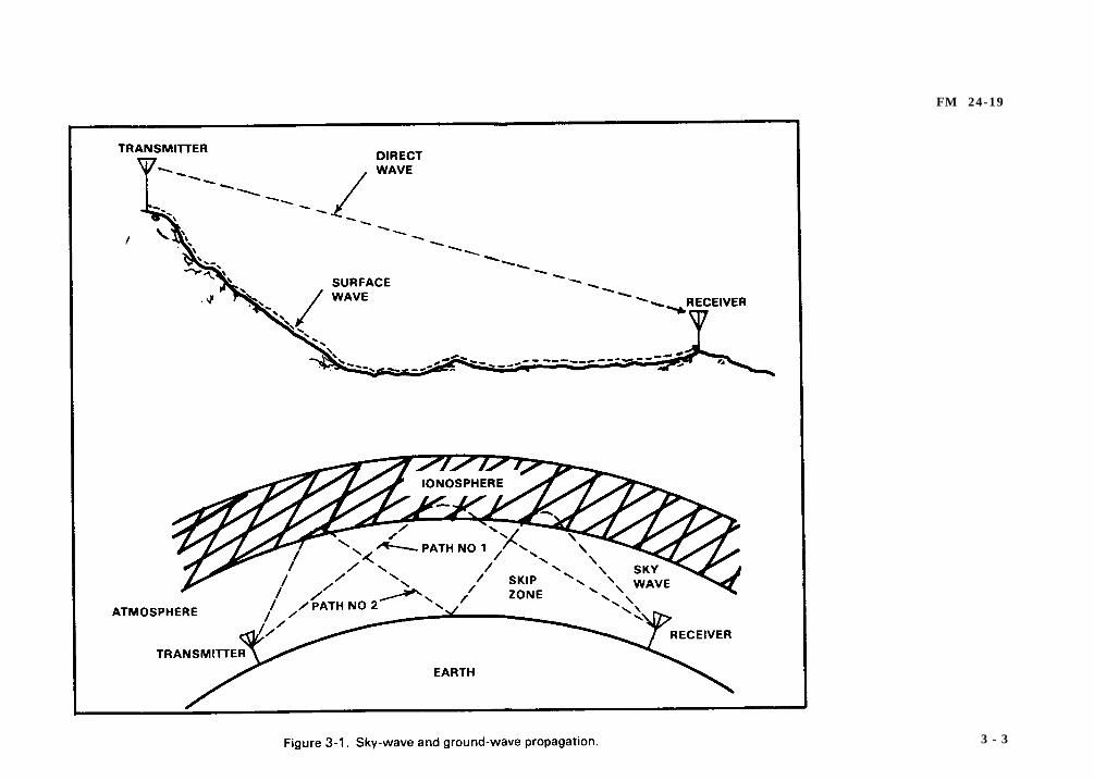
FM 24-19
3 - 3
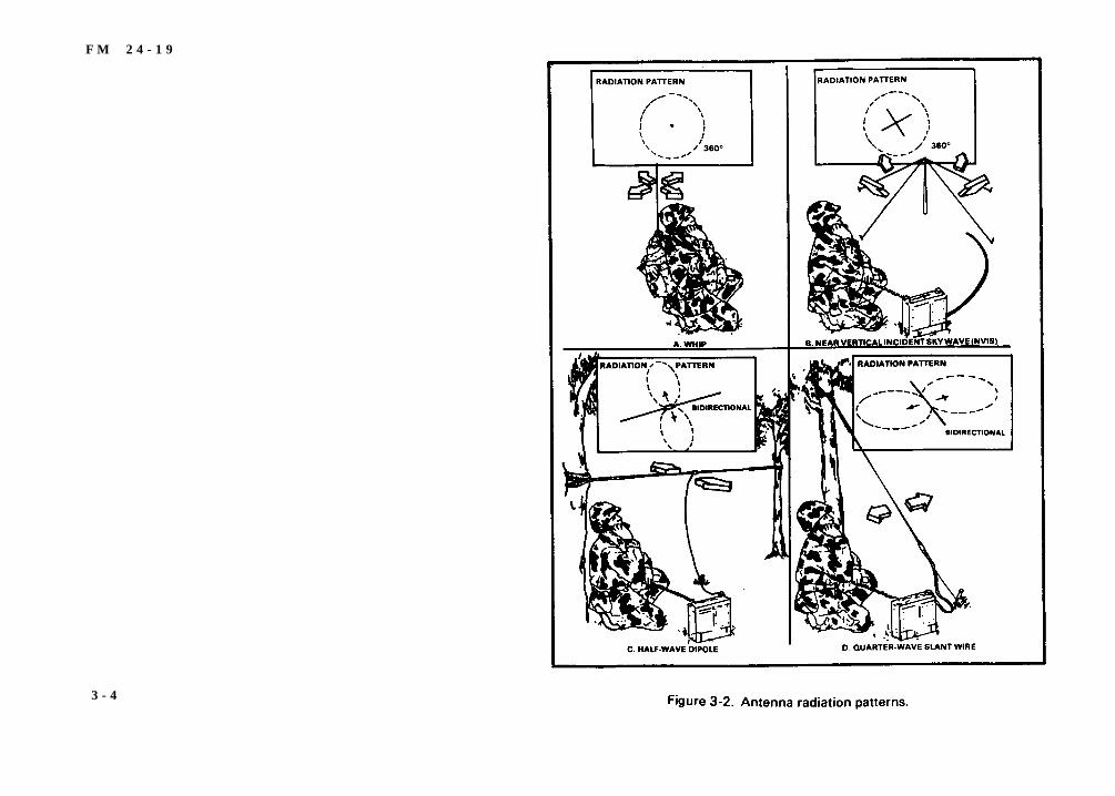
F M 2 4 - 1 9
3 - 4
F M 2 4 - 1 9
You may substitute a steel reinforcing rod, a steel fence poet, or ametal water or gas pipe cut to the right length for the ground stake.Ensure paint and rust are removed from such items. Substitutes forthe ground strap include battery cables or any heavy gauge wire. Donot use Field Wire WD-1 because it does not provide a suitableground. Drive the ground stake into the ground until the top of thestake is 2 to 4 inches above the ground. Attach one end of the groundstrap to the stake and the other end to the vehicle body. Ensure allpaint and rust are removed from connecting point of the vehiclebody to allow a good metal-to-metal contact.
c. When a whip antenna is mounted on a vehicle, the metal of thevehicle will affect the operation of the antenna. As a result, thedirection in which the vehicle is facing may also affect trans-mission and reception, particularly of distant or weak signals. Avehicle with a whip antenna mounted on its left rear side transmitsits strongest signal in a line running diagonally from the antennathrough the right front side of the vehicle. Similarly, an antennamounted on the right rear side of the vehicle radiates its strongestsignal in a direction diagonally toward the left front side. In somecases, the best direction can be determined by driving the vehicle ina small circle until the best reception is obtained.
Section III. Antenna RC-292
Antenna RC-292 is used to extend the distance range of the oldand new generation of FM field radio sets. The antenna consists ofone vertical radiating element and three ground plane elements.The lengths of these elements are determined by the operatingfrequency of the radio set. Refer to the antenna element selectionchart at Table 3-1. The antenna is elevated on a 30-foot sectionalmast which in turn is held erect by guy ropes and stakes. When theoperating frequency is changed, check the antenna elementselection chart. If the new frequency requires a change in elementlength, lower the antenna and add or subtract the required numberof elements.
3 - 5

FM 24-19
Section IV. Antenna Group OE-254/GRC
Description
Antenna Group OE-254/GRC is used to extend the range of theold and new generation of FM field radio sets. The antenna consistsof three upward and three downward extended radials. Theseradials remain the same length for all frequencies from 30 to 88MHz. The antenna is elevated on a 30-foot sectional mast held erectwith guy ropes and stakes.
NOTE: No change needs to be made in the number ofradials when a change of frequency is necessary.
3 - 6
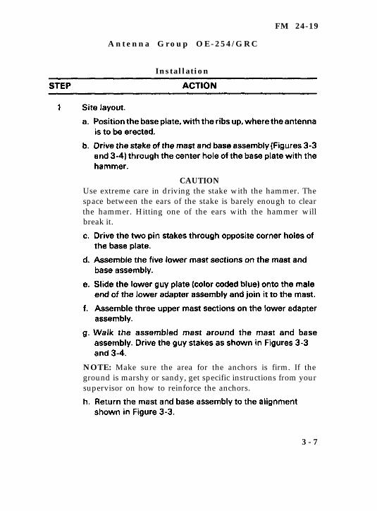
FM 24-19
A n t e n n a G r o u p O E - 2 5 4 / G R C
Installation
CAUTIONUse extreme care in driving the stake with the hammer. Thespace between the ears of the stake is barely enough to clearthe hammer. Hitting one of the ears with the hammer willbreak it.
NOTE: Make sure the area for the anchors is firm. If theground is marshy or sandy, get specific instructions from yoursupervisor on how to reinforce the anchors.
3 - 7
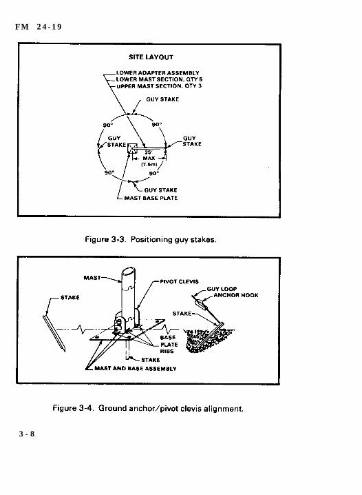
F M 2 4 - 1 9
3 - 8
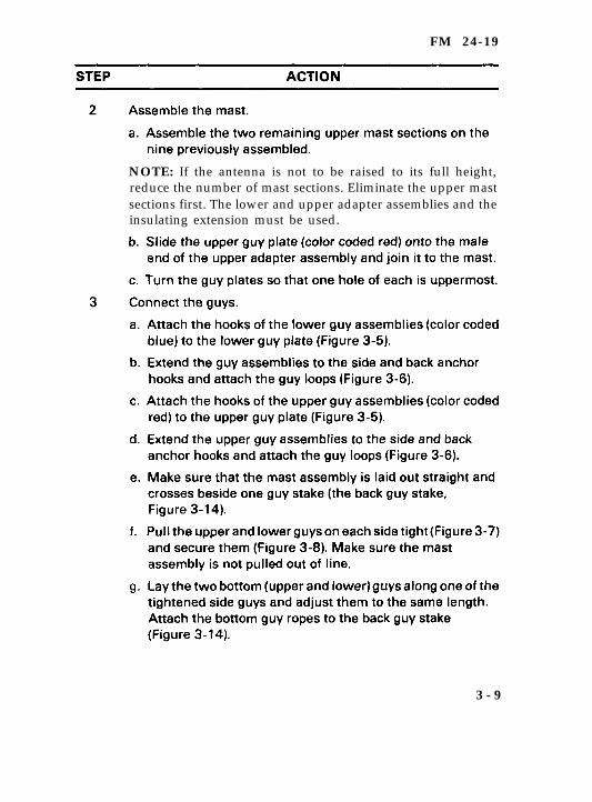
FM 24-19
NOTE: If the antenna is not to be raised to its full height,reduce the number of mast sections. Eliminate the upper mastsections first. The lower and upper adapter assemblies and theinsulating extension must be used.
3 - 9
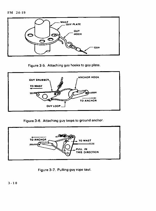
FM 24-19
3 - 1 0

F M 2 4 - 1 9
NOTE: Additional weatherproofing of the antenna assemblymay be made at this time by wiping the excess siliconecompound from the antenna assembly and wrapping eachjoint with electrical tape.
3 - 1 1
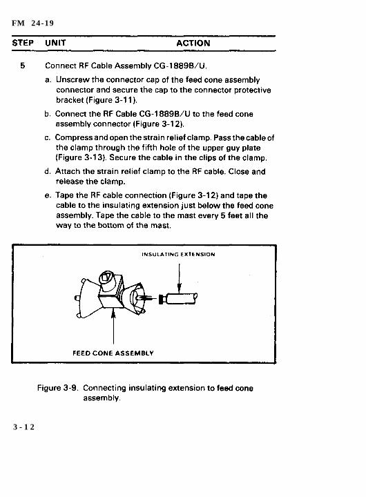
FM 24-19
3 - 1 2
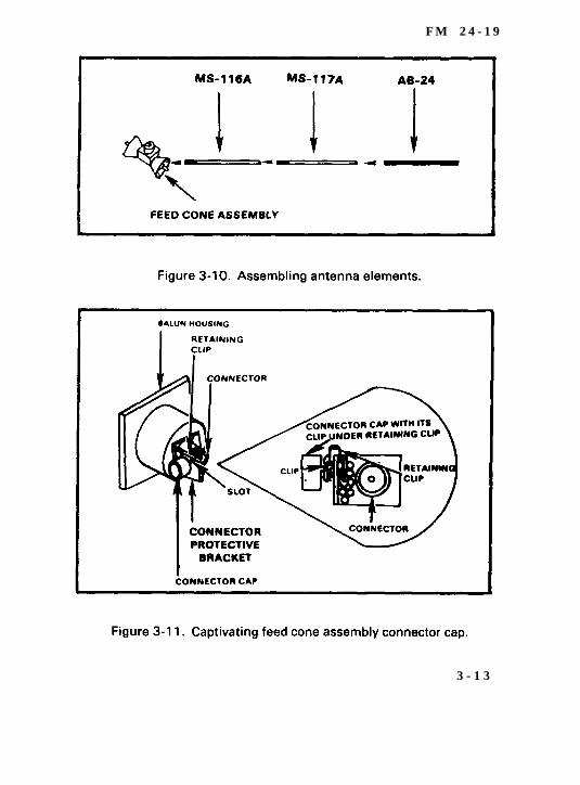
F M 2 4 - 1 9
3 - 1 3
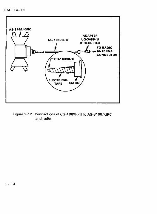
F M 2 4 - 1 9
3 - 1 4
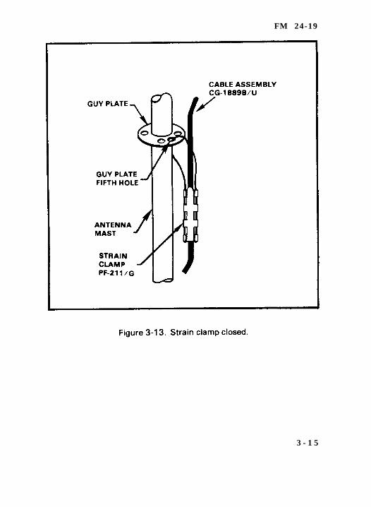
FM 24-19
3 - 1 5
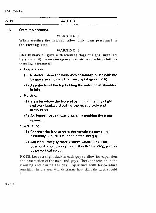
FM 24-19
WARNING 1When erecting the antenna, allow only team personnel inthe erecting area.
WARNING 2Clearly mark all guys with warning flags or signs (suppliedby your unit). In an emergency, use strips of white cloth aswarning streamers.
NOTE: Leave a slight slack in each guy to allow for expansionand contraction of the mast and guys. Check the tension in themorning and during the day. Experience with temperatureconditions in the area will determine how tight the guys shouldbe.
3 - 1 6
FM 24-19
WARNINGIf the weather in your area can cause ice to form on theantenna and guys, add extra guys to support the system.Rope off the area and post it with warning signs, such asbeware of falling ice. Keep a sharp aye on the anchors andguys. Check them daily and immediately before and afterbad weather.
NOTE: For AN/VRC-12 family FM radios with BNC typeantenna connectors, use the UG-349B/U adapter on the endof the CG-1886B/U RF cable (Figure 3-12).
3 - 1 7
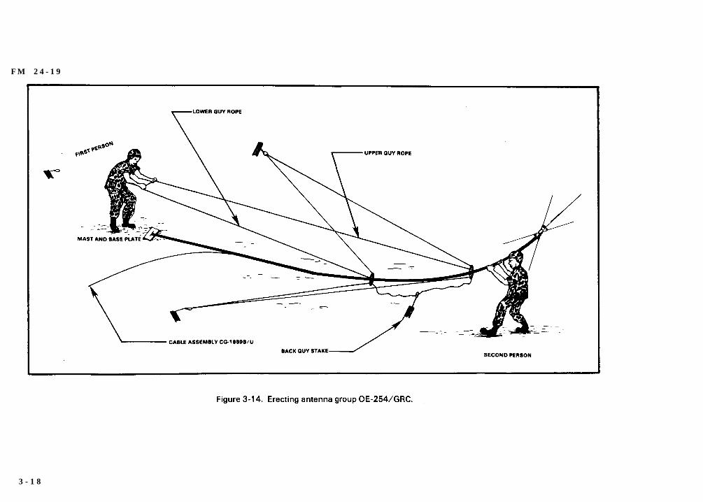
F M 2 4 - 1 9
3 - 1 8
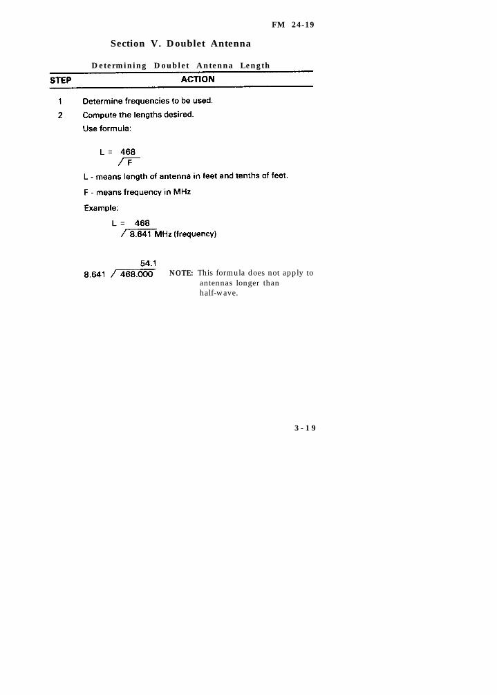
FM 24-19
Section V. Doublet Antenna
Determining Doublet Antenna Length
NOTE: This formula does not apply toantennas longer thanhalf-wave.
3 - 1 9

FM 24-19
Doublet Antenna
Determining Doublet Antenna Height
The height of the doublet antenna above the ground determinesthe radiation pattern, or take-off angle. The radiation pattern for adistance of 0 to 250 miles should be straight up. To determine theheight of your doublet antenna, use OTF. For daytime uses of 4.8 to9.7 MHz for a distance of 100 miles, use the formula for a quarter-wave. For nighttime uses of the same frequency of 4.8 to 9.7 MHz,use the formula for a tenth of a wave.
3 - 2 0
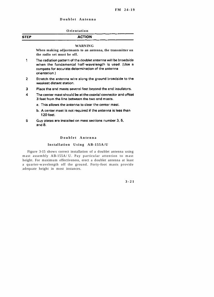
F M 2 4 - 1 9
D o u b l e t A n t e n n a
Orientation
WARNINGWhen making adjustmants to an antenna, the transmitter onthe radio set must be off.
D o u b l e t A n t e n n a
Installation Using AB-155A/U
Figure 3-15 shows correct installation of a doublet antenna usingmast assembly AB-155A/U. Pay particular attention to mastheight. For maximum effectiveness, erect a doublet antenna at leasta quarter-wavelength off the ground. Forty-foot masts provideadequate height in most instances.
3 - 2 1
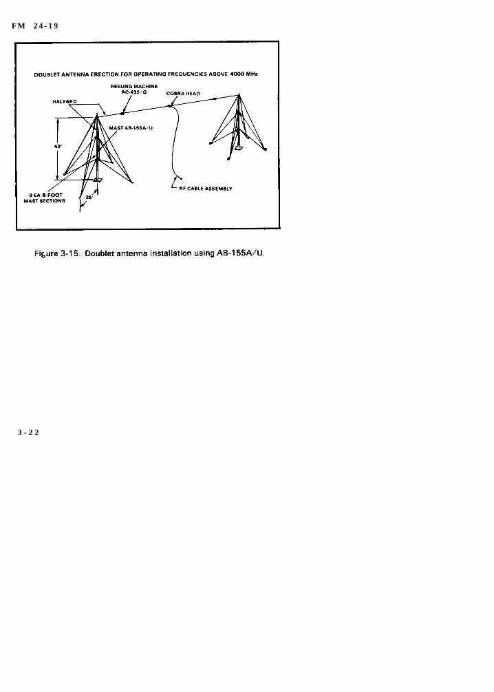
F M 2 4 - 1 9
3 - 2 2

FM 24-19
3 - 2 3
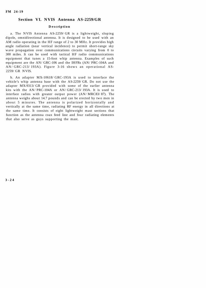
FM 24-19
Section VI. NVIS Antenna AS-2259/GR
Description
a. The NVIS Antenna AS-2259/GR is a lightweight, slopingdipole, omnidirectional antenna. It is designed to be used with anAM radio operating in the HF range of 2 to 30 MHz. It provides highangle radiation (near vertical incidence) to permit short-range skywave propagation over communications circuits varying from 0 to300 miles. It can be used with tactical HF radio communicationsequipment that tunes a 15-foot whip antenna. Examples of suchequipment are the AN/GRC-106 and the IHFRs (AN/PRC-104A andAN/GRC-213/193A). Figure 3-16 shows an operational AS-2259/GR NVIS.
b. An adapter MX-10618/GRC-193A is used to interface thevehicle’s whip antenna base with the AS-2259/GR. Do not use theadapter MX-9313/GR provided with some of the earlier antennakits with the AN/PRC-104A or AN/GRC-213/193A. It is used tointerface radios with greater output power (AN/MRC83/87). Theantenna weighs about 14.7 pounds and can be erected by two men inabout 5 minutes. The antenna is polarized horizontally andvertically at the same time, radiating RF energy in all directions atthe same time. It consists of eight lightweight mast sections thatfunction as the antenna coax feed line and four radiating elementsthat also serve as guys supporting the mast.
3 - 2 4
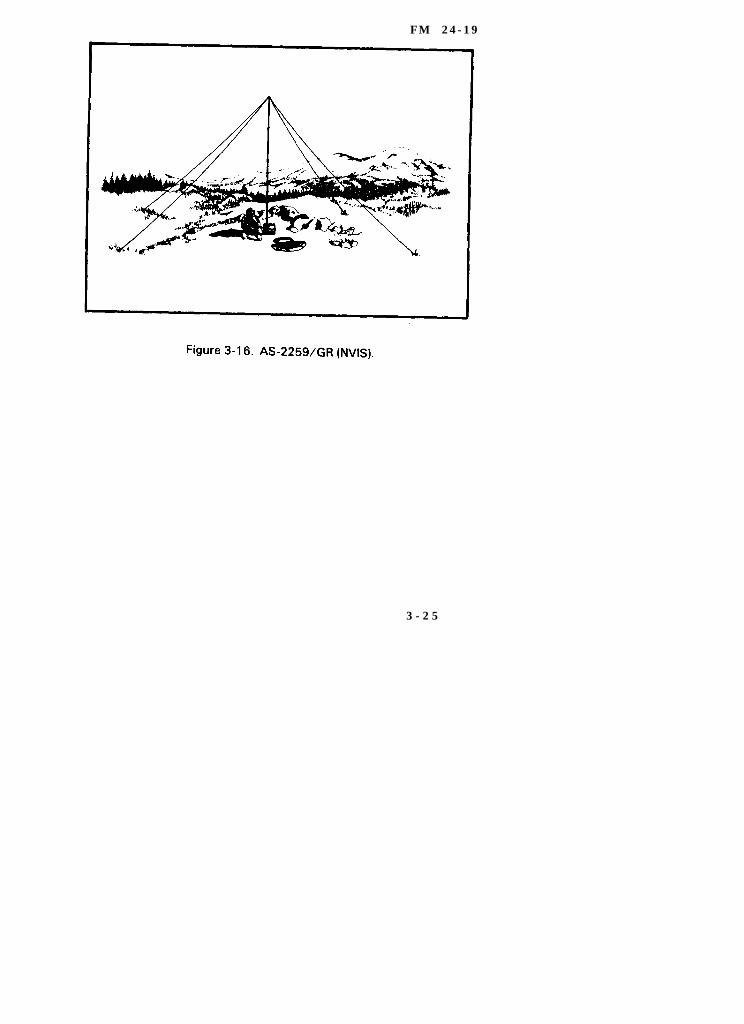
F M 2 4 - 1 9
3 - 2 5
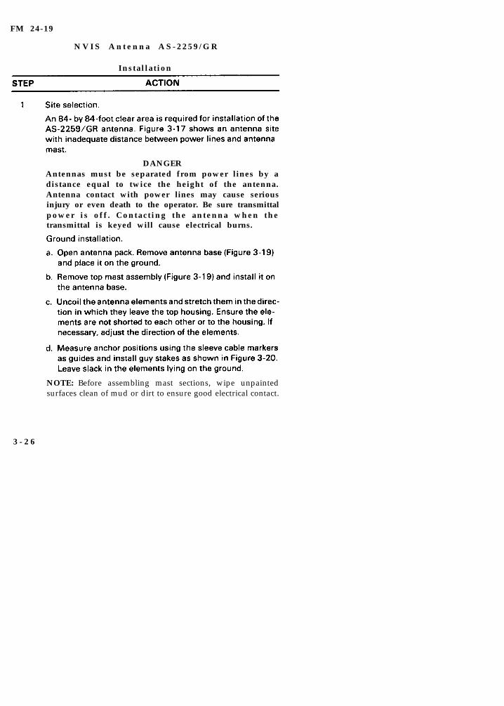
FM 24-19
N V I S A n t e n n a A S - 2 2 5 9 / G R
Installation
DANGERAntennas must be separated from power lines by adistance equal to twice the height of the antenna.Antenna contact with power lines may cause seriousinjury or even death to the operator. Be sure transmittalpower is off . Contacting the antenna when thetransmittal is keyed will cause electrical burns.
NOTE: Before assembling mast sections, wipe unpaintedsurfaces clean of mud or dirt to ensure good electrical contact.
3 - 2 6
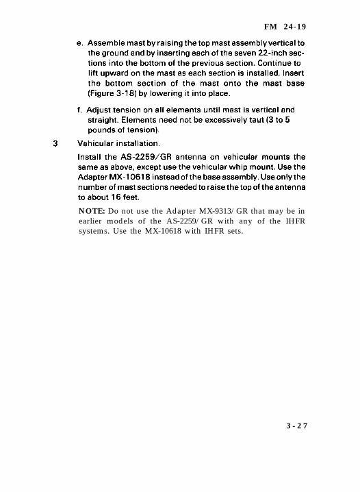
FM 24-19
NOTE: Do not use the Adapter MX-9313/GR that may be inearlier models of the AS-2259/GR with any of the IHFRsystems. Use the MX-10618 with IHFR sets.
3 - 2 7
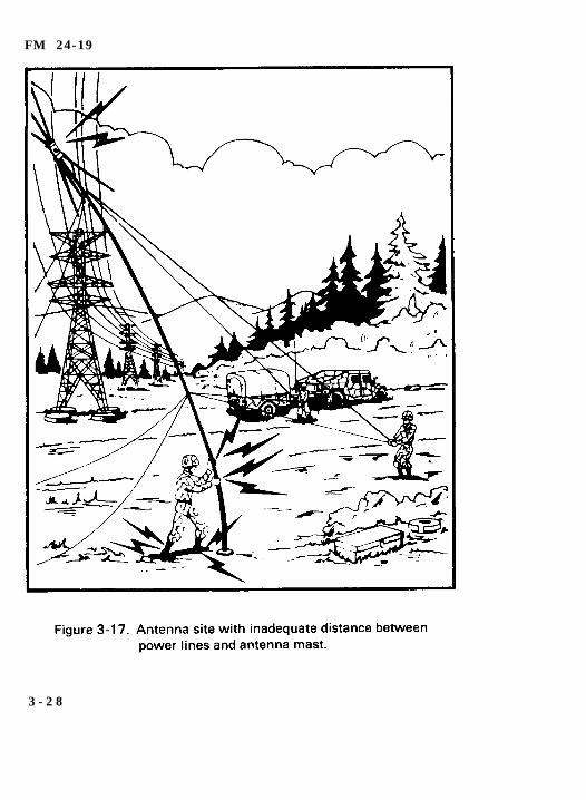
FM 24-19
3 - 2 8
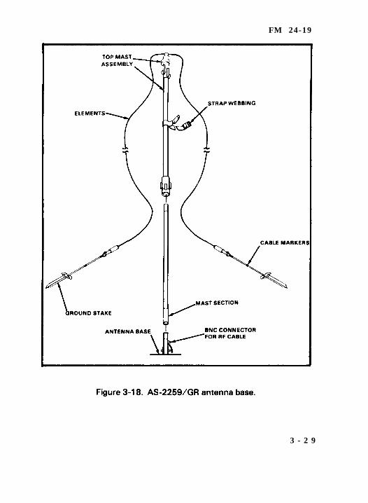
FM 24-19
3 - 2 9
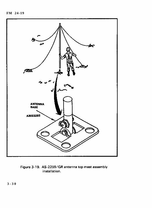
FM 24-19
3 - 3 0
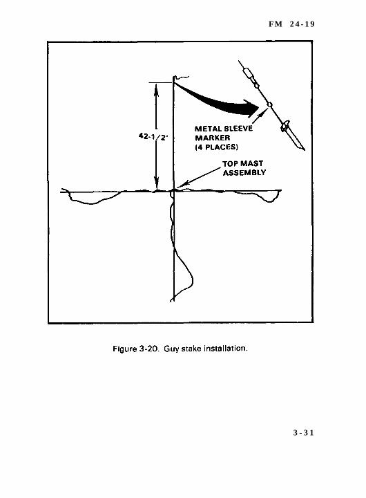
F M 2 4 - 1 9
3 - 3 1
FM 24-19
Section VII. Field Expedients for Antennas
a. Antennas are sometimes broken or damaged resulting infailed or poor communications. If a spare is available, replace thedamaged antenna. When there is no spare, fabricate an emergencyantenna. For more information on how to repair and fabricateantennas refer to FM 24-18. The following suggest ways toconstruct an emergency antenna.
(1) The best wire for antennas is copper or aluminum. In anemergency, however, use any wire available. WD-1/TT is suitablefor this purpose.
(2) The exact length of many antennas is critical. Therefore, thelength of the emergency antenna should be the same as the lengthof the antenna it replaces.
(3) Antennas supported by trees can usually survive heavywindstorms if the trunk of a tree or a stout limb is used for support.To keep the antenna taut and to prevent it from breaking orstretching, attach a spring or a strip of old inner tube to one end ofthe antenna, or pass a rope through a pulley or eye hook, attach therope to the end of the antenna, and load the rope with a heavyweight to keep the antenna taut.
(4) Guys used to hold antenna supports are made of rope or wire.To ensure that wire guys will not affect the operation of theantenna, cut the wire into several short lengths and connect thepieces with insulators. Small pieces of dry wood, bottles, or evensuitably shaped stones may be used.
b. An improvised antenna may change the performance of aradio set. Use either of the two following expedient methods todetermine whether the improvised antenna is operating properly.
(1) The distant receiver may be used to test the antenna. If thesignal received from a station is strong, the antenna is operatingsatisfactorily. If the signal is weak, adjust the height and length ofthe antenna and transmission line to receive the strongest signal at
3 - 3 2
FM 24-19
a given setting of the volume control of the receiver. If your set isequipped with a power or SWR meter, use this device to adjust yourantenna.
(2) In some radio sets, the transmitter is used to adjust theantenna. First, set the controls of the transmitter in the properposition for normal operation; then, tune the system by adjustingthe antenna height, length, and the transmission line length toobtain the best transmission output.
c. When a whip antenna is broken into two sections, the portionof the antenna that is broken off can be connected to the portionattached to the base fitting by joining the sections together. Whenboth parts of the broken whip are available and usable, connect thetwo broken ends together and wrap with wire, ensuring thatwrapping is clean and tight. Lash pole or branch to antenna untilantenna will stand alone. When the portion of whip that is broken ismissing or unusable, add a piece of wire that is nearly the samelength as the broken section. Then, lash a pole the length of theantenna securely to the base section of the antenna and tie wire tothe top of pole. If possible, solder the connections.
d. Emergency repair of wire antennas can be grouped into twocategories: repair or replacement of the wire used as an antenna ortransmission line; and repair or replacement of the assembly usedto support the antenna wires.
(1) When one or more wires on an antenna are broken, theantenna can be repaired by reconnecting the broken wires. To dothis, lower the antenna to the ground, clean the surface of the wire,and twist the wires together. Whenever possible, solder theconnections.
(2) If the antenna is damaged beyond repair, substitute anotherantenna. If antenna sections are not available, WD-1 (field wire)can be used as a substitute. Ensure the length of the wire is the samelength as the original antenna and you have a good wire to antennacontact.
3 - 3 3
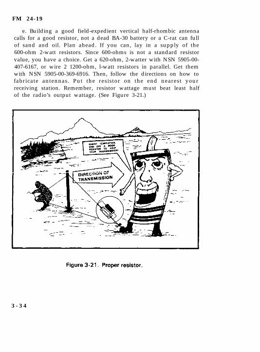
FM 24-19
e. Building a good field-expedient vertical half-rhombic antennacalls for a good resistor, not a dead BA-30 battery or a C-rat can fullof sand and oil. Plan ahead. If you can, lay in a supply of the600-ohm 2-watt resistors. Since 600-ohms is not a standard resistorvalue, you have a choice. Get a 620-ohm, 2-watter with NSN 5905-00-407-6167, or wire 2 1200-ohm, l-watt resistors in parallel. Get themwith NSN 5905-00-369-6916. Then, follow the directions on how tofabricate antennas. Put the resistor on the end nearest yourreceiving station. Remember, resistor wattage must beat least halfof the radio’s output wattage. (See Figure 3-21.)
3 - 3 4

FM 24-19
Section VIII. Grounding Systems
WARNINGIf underground pipes or tanks are used, ensure they do notcontain gasoline, oil, or other flammable liquids or gas.
3 - 3 5

F M 2 4 - 1 9
NOTE: Use the “wrap method” if a terminal screw or a groundclamp is not available. Bind the ground strap to the rod by usingstrong, flexible bare wire. Wrap about 24 turns of the wirearound the strap and the rod, then solder the wire and strap tothe rod. If solder is not available, twist the ends of the wire astight as you can, then tape the connection to keep outmoisture.
3 - 3 6
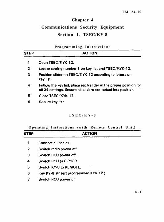
FM 24-19
Chapter 4
Communications Security Equipment
Section I. TSEC/KY-8
P r o g r a m m i n g I n s t r u c t i o n s
T S E C / K Y - 8
Operating Instructions (with Remote Control Unit)
4 - 1
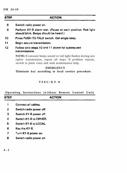
FM 24-19
NOTE: If constant beeps sound or red light flashes during anycipher transmission, repeat all steps. If problem repeats,switch to plain voice and seek maintenance help.
EMERGENCYEliminate key according to local zeroize procedure.
T S E C / K Y - 8
Operating Instructions (without Remote Control Unit)
4 - 2
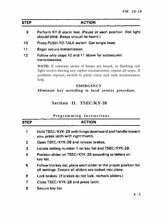
FM 24-19
NOTE: If constant series of beeps are heard, or flashing redlight occurs during any cipher transmission, repeat all steps. Ifproblem repeats, switch to plain voice and seek maintenancehelp.
EMERGENCYEliminate key according to local zeroize procedure.
Section II. TSEC/KY-38
P r o g r a m m i n g I n s t r u c t i o n s
4 - 3
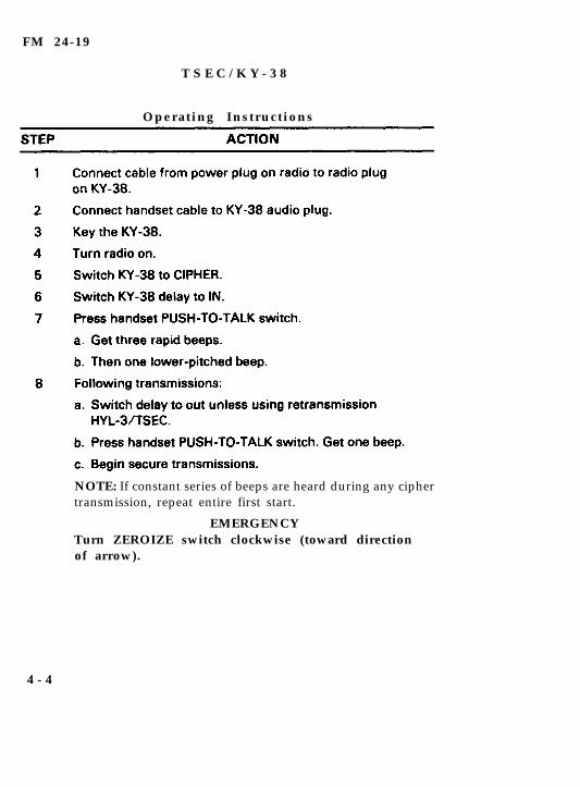
FM 24-19
T S E C / K Y - 3 8
Operating Instructions
NOTE: If constant series of beeps are heard during any ciphertransmission, repeat entire first start.
EMERGENCYTurn ZEROIZE switch clockwise (toward directionof arrow).
4 - 4
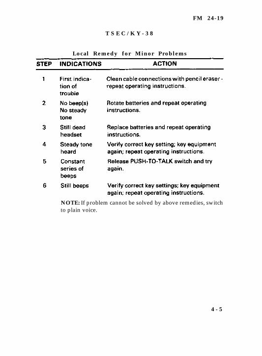
FM 24-19
T S E C / K Y - 3 8
Local Remedy for Minor Problems
NOTE: If problem cannot be solved by above remedies, switchto plain voice.
4 - 5

FM 24-19
Section III. HYL-3/TSEC
Prestart Operating Procedures (al l Modes)
H Y L - 3 / T S E C
R e t r a n s m i s s i o n P r o c e d u r e s
4 - 6
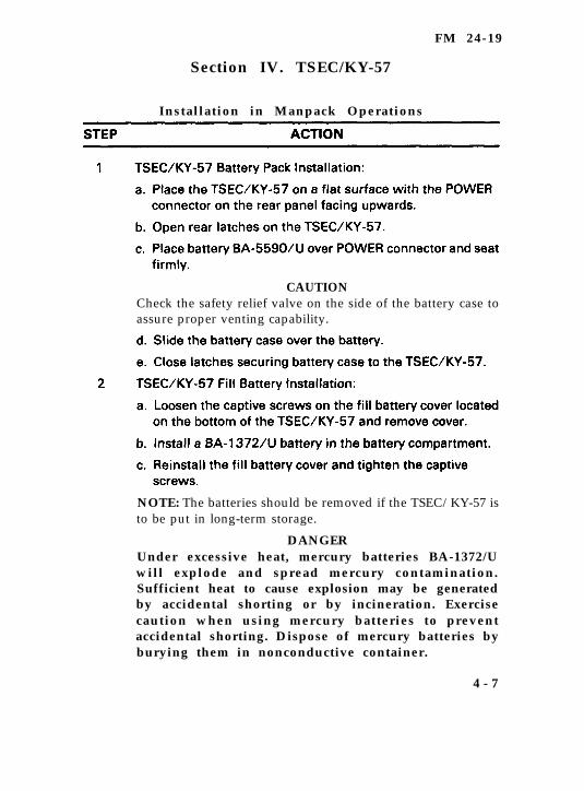
FM 24-19
Section IV. TSEC/KY-57
Installation in Manpack Operations
CAUTIONCheck the safety relief valve on the side of the battery case toassure proper venting capability.
NOTE: The batteries should be removed if the TSEC/KY-57 isto be put in long-term storage.
DANGERUnder excessive heat, mercury batteries BA-1372/Uwill explode and spread mercury contamination.Sufficient heat to cause explosion may be generatedby accidental shorting or by incineration. Exercisecaution when using mercury batteries to preventaccidental shorting. Dispose of mercury batteries byburying them in nonconductive container.
4 - 7
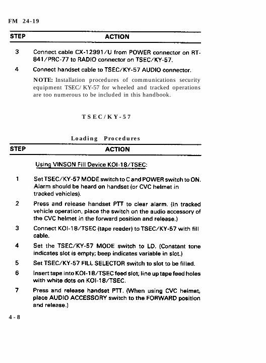
FM 24-19
NOTE: Installation procedures of communications securityequipment TSEC/KY-57 for wheeled and tracked operationsare too numerous to be included in this handbook.
T S E C / K Y - 5 7
Loading Procedures
4 - 8
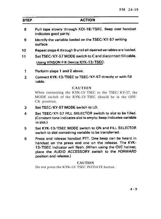
FM 24-19
CAUTIONWhen connecting the KYK-13/TSEC to the TSEC/KY-57, theMODE switch of the KYK-13/TSEC should be in the OFF/CK position.
CAUTIONDo not press the KYK-13/TSEC INITIATE button.
4 - 9
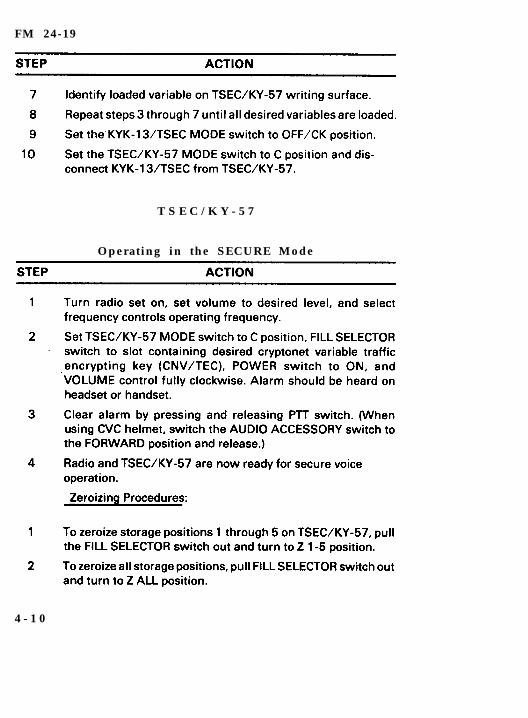
FM 24-19
T S E C / K Y - 5 7
Operating in the SECURE Mode
4 - 1 0
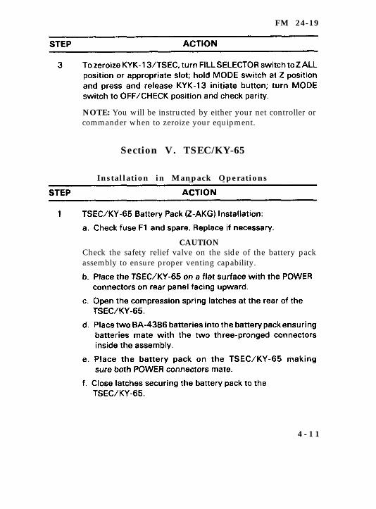
FM 24-19
NOTE: You will be instructed by either your net controller orcommander when to zeroize your equipment.
Section V. TSEC/KY-65
Installation in Manpack Operations
CAUTIONCheck the safety relief valve on the side of the battery packassembly to ensure proper venting capability.
4 - 1 1
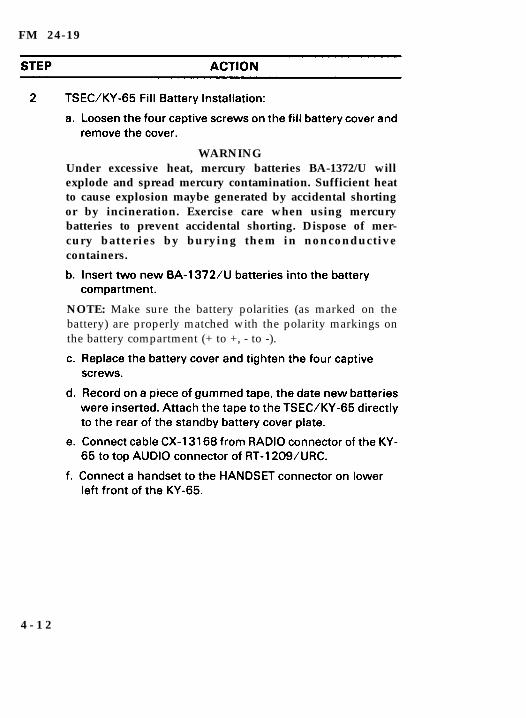
FM 24-19
WARNINGUnder excessive heat, mercury batteries BA-1372/U willexplode and spread mercury contamination. Sufficient heatto cause explosion maybe generated by accidental shortingor by incineration. Exercise care when using mercurybatteries to prevent accidental shorting. Dispose of mer-cury batteries by burying them in nonconductivecontainers.
NOTE: Make sure the battery polarities (as marked on thebattery) are properly matched with the polarity markings onthe battery compartment (+ to +, - to -).
4 - 1 2
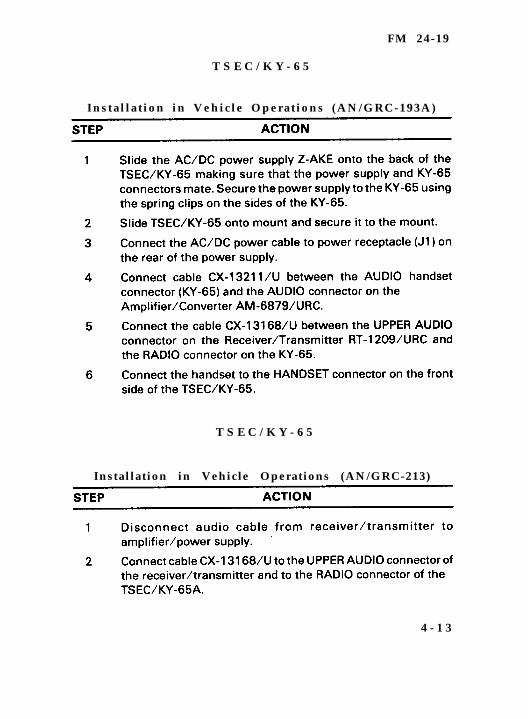
FM 24-19
T S E C / K Y - 6 5
Instal lat ion in Vehicle Operations (AN/GRC-193A)
T S E C / K Y - 6 5
Installation in Vehicle Operations (AN/GRC-213)
4 - 1 3
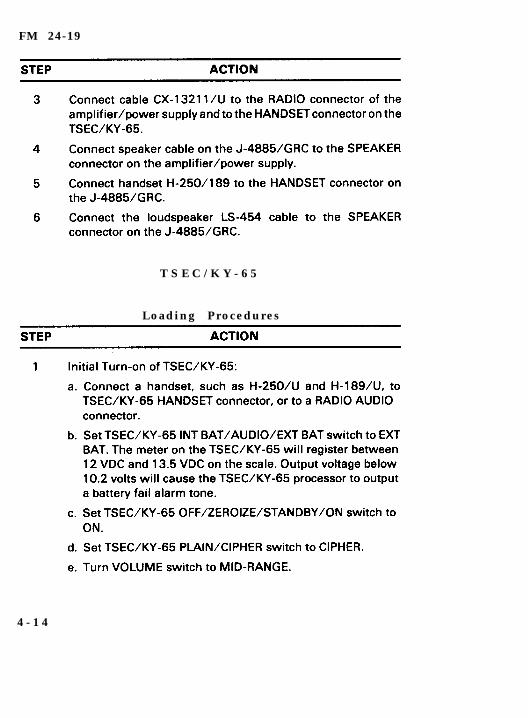
FM 24-19
T S E C / K Y - 6 5
Loading Procedures
4 - 1 4

F M 2 4 - 1 9
NOTE: Prior to FILL operations, the local operator should setthe DELAY OUT/DELAY IN/SIG CLR switch to the SIG CLRposition, transmit to distant station and request that operatorto set his DELAY OUT/DELAY IN/SIG CLR switch to the SIGCLR position and, using the VOLUME CONTROL, adjust thevolume of the incoming audio signal to obtain a center scalereading on the meter. Request the distant operator transmit tolocal operator and perform the same procedures as above. Thisprocedure will greatly improve the voice quality of the system.
NOTE: Ensure the rubber grommet is in the KYK-13/TSECPI connector and the TSEC/KY-65 is in the CIPHER mode.
4 - 1 5
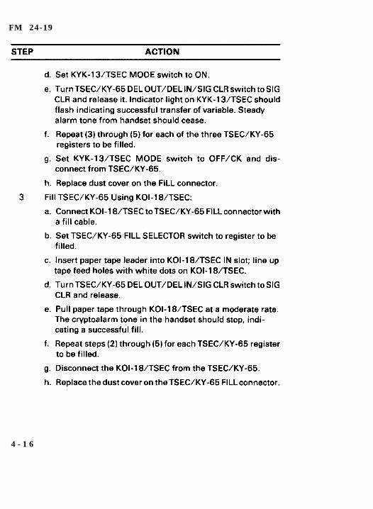
FM 24-19
4 - 1 6

FM 24-19
T S E C / K Y - 6 5
O p e r a t i o n s
NOTE: Amber light on front of TSEC/KY-65 will flashcontinuously during receipt of secure voice communications.Meter on the front of the TSEC/KY-65 will indicate thereceiving and transmitting audio level. After receiving a ciphertest communication, wait until postamble stops beforeinitiating a transmission.
4 - 1 7
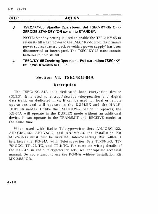
FM 24-19
NOTE: Standby setting is used to enable the TSEC/KY-65 toretain its fill when power to the TSEC/KY-65 from the primarypower source (battery pack or vehicle power supply) has beendisconnected or interrupted. The TSEC/KY-65 must containbatteries to hold its fill.
Section VI. TSEC/KG-84A
Description
The TSEC/KG-84A is a dedicated loop encryption device(DLED). It is used to encrypt/decrypt teletypewriter and digitaldata traffic on dedicated links. It can be used for local or remoteoperations and will operate in the DUPLEX and the HALF-DUPLEX modes. Unlike the TSEC\KW-7, which it replaces, theKG-84A will operate in the DUPLEX mode without an additionaldevice. It can operate in the TRANSMIT and RECEIVE modes atthe same time.
When used with Radio Teletypewriter Sets AN/GRC-122,AN/GRC-142, AN/VSC-2, and AN/VSC-3, the Installation KitMK-2488/G must first be installed. Interconnecting Box J-4024/Uinterfaces the KG-84A with Teletypewriter Sets TT-98/FG, TT-76/GGC, TT-122/TG, and TT-4/TG. For complete wiring details ofthe KG-84A in radio teletypewriter sets, see appropriate technicalmanual. Do not attempt to use the KG-84A without Installation KitMK-2488/GR.
4 - 1 8
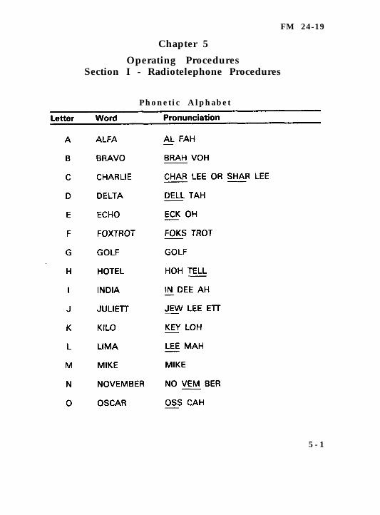
FM 24-19
Chapter 5
Operating ProceduresSection I - Radiotelephone Procedures
Phonetic Alphabet
5 - 1
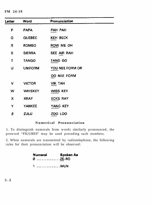
FM 24-19
Numerical Pronunciation
1. To distinguish numerals from words similarly pronounced, theproword “FIGURES” may be used preceding such numbers.
2. When numerals are transmitted by radiotelephone, the followingrules for their pronunciation will be observed:
5 - 2
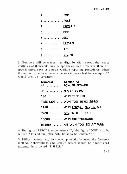
FM 24-19
3. Numbers will be transmitted digit by digit except that exactmultiples of thousands may be spoken as such. However, there arespecial cases, such as anti-air warfare reporting procedures, whenthe normal pronunciation of numerals is prescribed for example, 17would then be “seventeen.”
4. The figure “ZERO” is to be written “0,” the figure “ONE” is to bewritten “1” and the letter “ZULU” is to be written “Z.”
5. Difficult words may be spelled phonetically using the four-stepmethod. Abbreviations and isolated letters should be phonetisizedwithout the proword “I SPELL.”
5 - 3
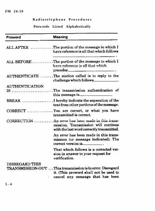
FM 24-19
R a d i o t e l e p h o n e P r o c e d u r e s
Prowords Listed Alphabetically
5 - 4
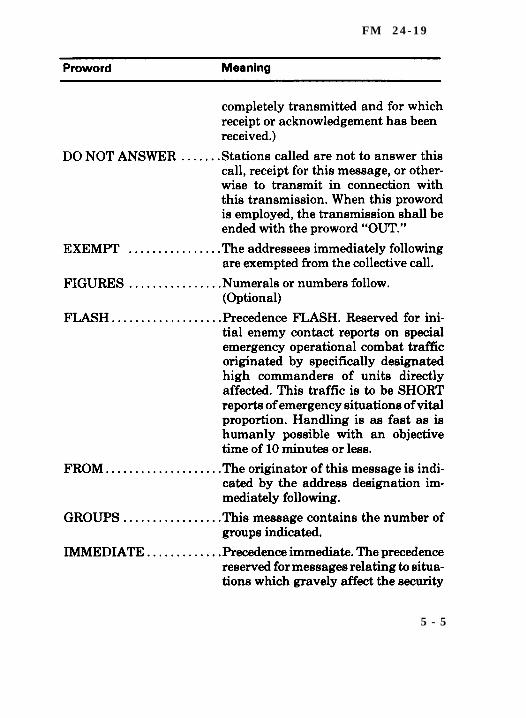
F M 2 4 - 1 9
5 - 5
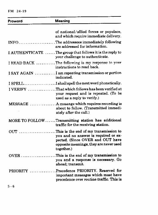
FM 24-19
5 - 6
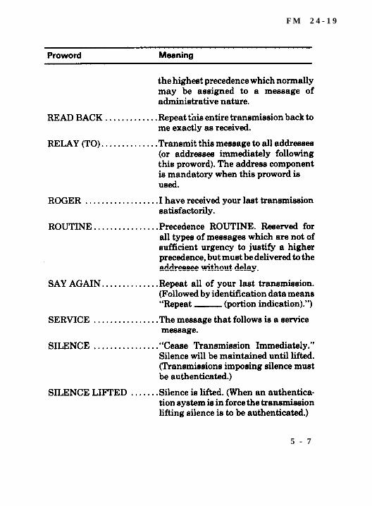
F M 2 4 - 1 9
5 - 7
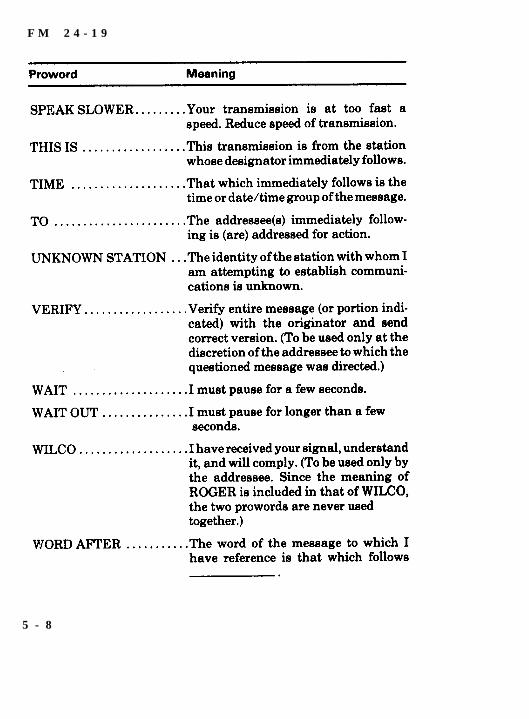
F M 2 4 - 1 9
5 - 8
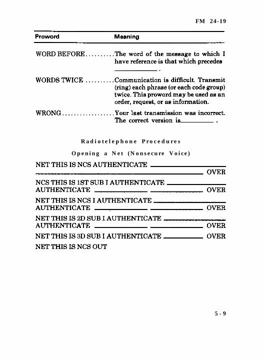
FM 24-19
R a d i o t e l e p h o n e P r o c e d u r e s
Opening a Net (Nonsecure Voice)
5 - 9
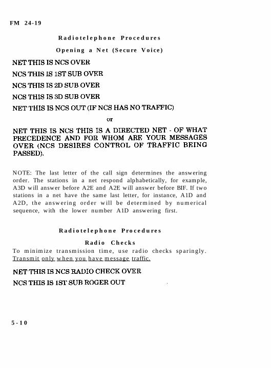
FM 24-19
R a d i o t e l e p h o n e P r o c e d u r e s
Opening a Net (Secure Voice)
NOTE: The last letter of the call sign determines the answeringorder. The stations in a net respond alphabetically, for example,A3D will answer before A2E and A2E will answer before BIF. If twostations in a net have the same last letter, for instance, A1D andA2D, the answering order will be determined by numericalsequence, with the lower number A1D answering first.
R a d i o t e l e p h o n e P r o c e d u r e s
R a d i o C h e c k sTo minimize transmission time, use radio checks sparingly.Transmit only when you have message traffic.
5 - 1 0
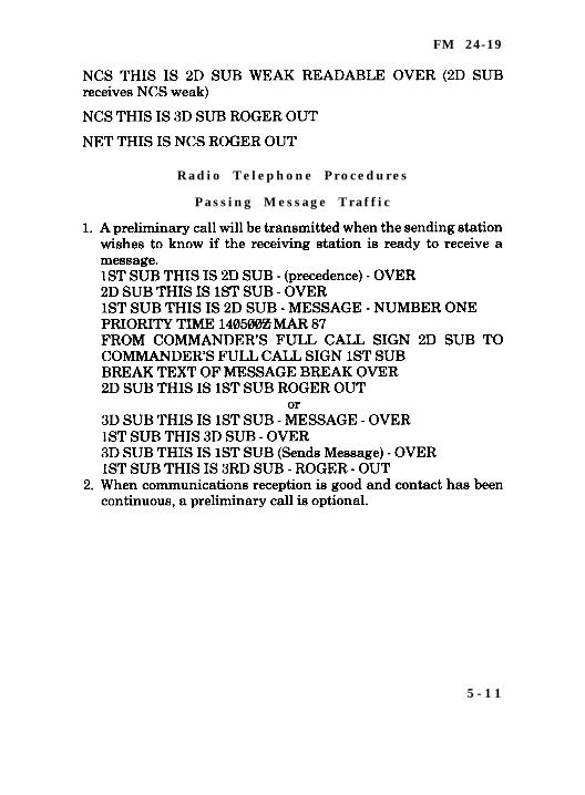
FM 24-19
R a d i o T e l e p h o n e P r o c e d u r e s
P a s s i n g M e s s a g e T r a f f i c
5 - 1 1
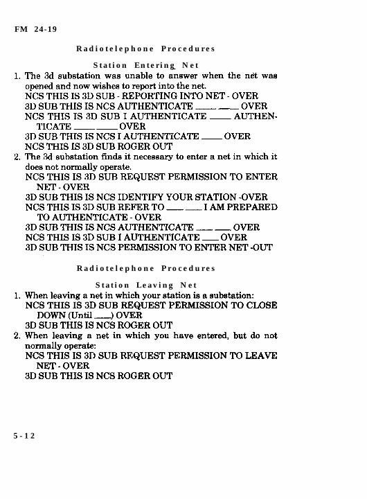
FM 24-19
R a d i o t e l e p h o n e P r o c e d u r e s
S t a t i o n E n t e r i n g N e t
R a d i o t e l e p h o n e P r o c e d u r e s
S t a t i o n L e a v i n g N e t
5 - 1 2
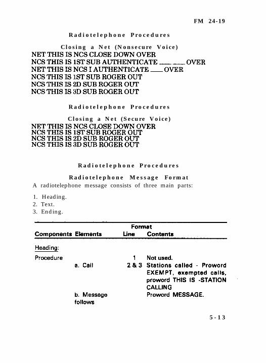
FM 24-19
R a d i o t e l e p h o n e P r o c e d u r e s
Closing a Net (Nonsecure Voice)
R a d i o t e l e p h o n e P r o c e d u r e s
Closing a Net (Secure Voice)
R a d i o t e l e p h o n e P r o c e d u r e s
R a d i o t e l e p h o n e M e s s a g e F o r m a tA radiotelephone message consists of three main parts:
1. Heading.2. Text.3. Ending.
5 - 1 3
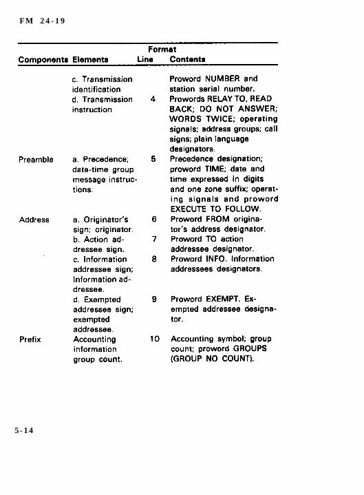
F M 2 4 - 1 9
5 - 1 4
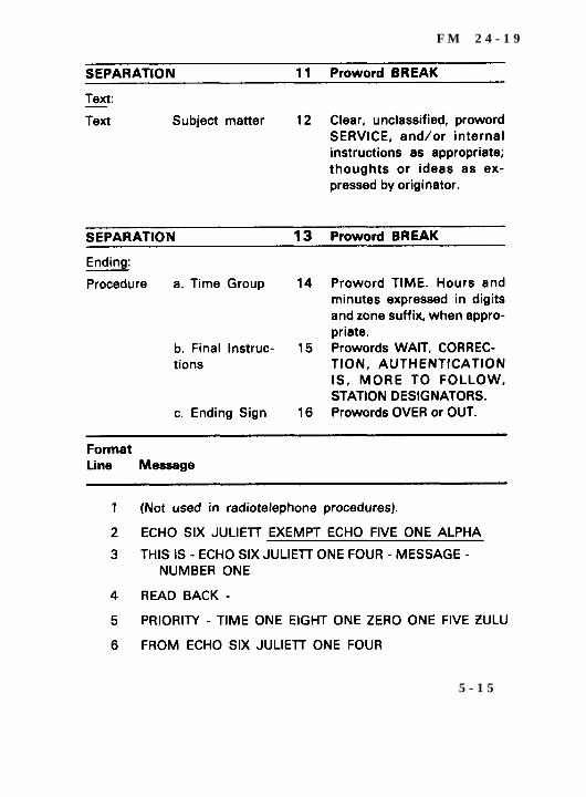
F M 2 4 - 1 9
5 - 1 5
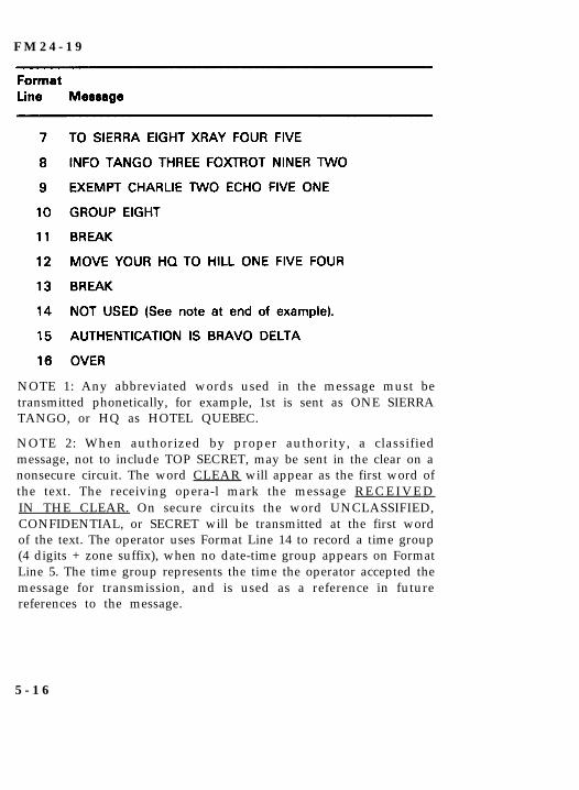
F M 2 4 - 1 9
NOTE 1: Any abbreviated words used in the message must betransmitted phonetically, for example, 1st is sent as ONE SIERRATANGO, or HQ as HOTEL QUEBEC.
NOTE 2: When authorized by proper authority, a classifiedmessage, not to include TOP SECRET, may be sent in the clear on anonsecure circuit. The word CLEAR will appear as the first word ofthe text. The receiving opera-l mark the message R E C E I V E DIN THE CLEAR. On secure circuits the word UNCLASSIFIED,CONFIDENTIAL, or SECRET will be transmitted at the first wordof the text. The operator uses Format Line 14 to record a time group(4 digits + zone suffix), when no date-time group appears on FormatLine 5. The time group represents the time the operator accepted themessage for transmission, and is used as a reference in futurereferences to the message.
5 - 1 6
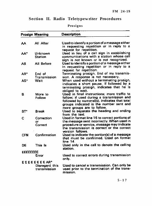
FM 24-19
Section II. Radio Teletypewriter Procedures
Prosigns
5 - 1 7
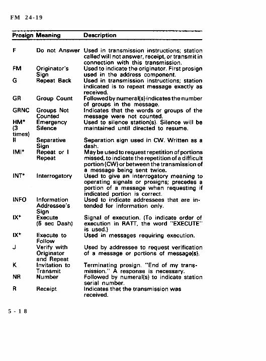
F M 2 4 - 1 9
5 - 1 8
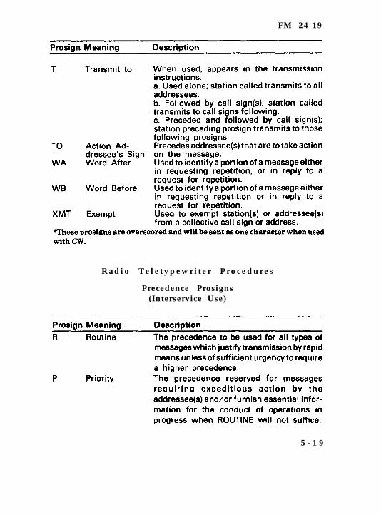
FM 24-19
R a d i o T e l e t y p e w r i t e r P r o c e d u r e s
Precedence Prosigns(Interservice Use)
5 - 1 9
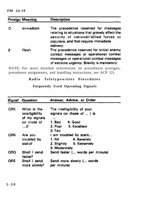
FM 24-19
NOTE: For more detailed information on precedence prosigns,precedence assignments, and handling instructions, see ACP 121.
R a d i o T e l e t y p e w r i t e r P r o c e d u r e s
Frequently Used Operating Signa1s
5 - 2 0
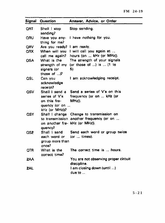
FM 24-19
5 - 2 1
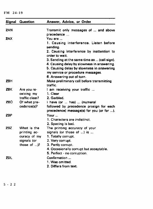
F M 2 4 - 1 9
5 - 2 2
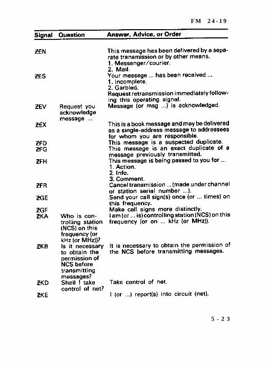
F M 2 4 - 1 9
5 - 2 3
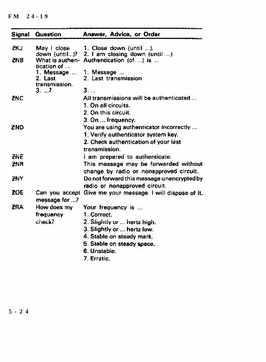
F M 2 4 - 1 9
5 - 2 4
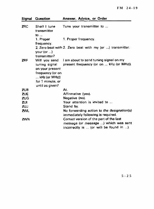
F M 2 4 - 1 9
5 - 2 5
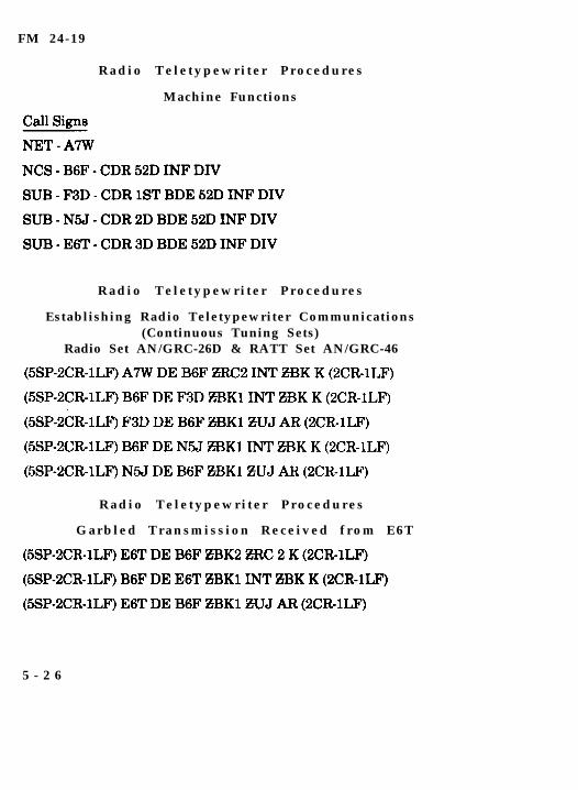
FM 24-19
R a d i o T e l e t y p e w r i t e r P r o c e d u r e s
Machine Functions
R a d i o T e l e t y p e w r i t e r P r o c e d u r e s
Establishing Radio Teletypewriter Communications(Continuous Tuning Sets)
Radio Set AN/GRC-26D & RATT Set AN/GRC-46
R a d i o T e l e t y p e w r i t e r P r o c e d u r e s
G a r b l e d T r a n s m i s s i o n R e c e i v e d f r o m E 6 T
5 - 2 6

FM 24-19
R a d i o T e l e t y p e w r i t e r P r o c e d u r e s
Establishing Radio Teletypewriter Communications(Digital Tuning Sets)
NOTE: ZKB is used in radio teletypewriter communications whenthe NCS has not been designatedin the SOI or when alternate NCShas assumed command of the net. EKB is used in radio teletypewriter communications when the NCS wants to control the net. TheNCS may want to control the net when the net has high messagetraffic. Also, if the net has numerous subs, the NCS may control thenet to avoid confusion.
R a d i o T e l e t y p e w r i t e r P r o c e d u r e s
Opening a Net
5 - 2 7
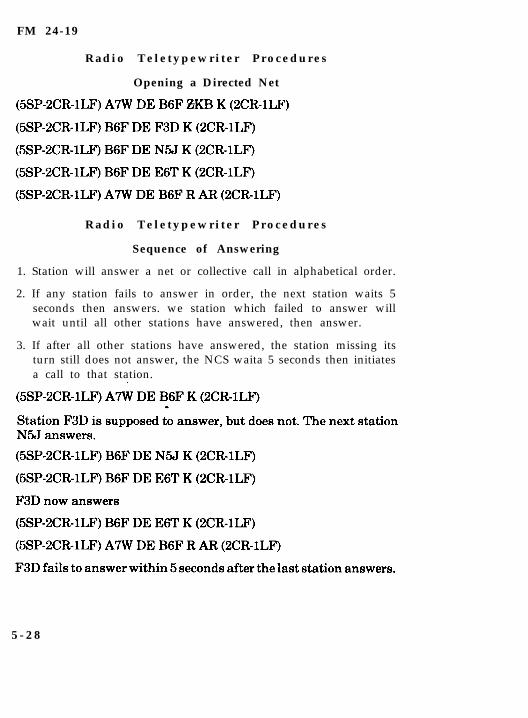
FM 24-19
R a d i o T e l e t y p e w r i t e r P r o c e d u r e s
Opening a Directed Net
R a d i o T e l e t y p e w r i t e r P r o c e d u r e s
Sequence of Answering
1. Station will answer a net or collective call in alphabetical order.
2. If any station fails to answer in order, the next station waits 5seconds then answers. we station which failed to answer willwait until all other stations have answered, then answer.
3. If after all other stations have answered, the station missing itsturn still does not answer, the NCS waita 5 seconds then initiatesa call to that station.
5 - 2 8
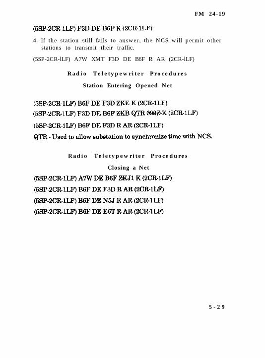
FM 24-19
4. If the station still fails to answer, the NCS will permit otherstations to transmit their traffic.
(5SP-2CR-lLF) A7W XMT F3D DE B6F R AR (2CR-lLF)
R a d i o T e l e t y p e w r i t e r P r o c e d u r e s
Station Entering Opened Net
R a d i o T e l e t y p e w r i t e r P r o c e d u r e s
Closing a Net
5 - 2 9
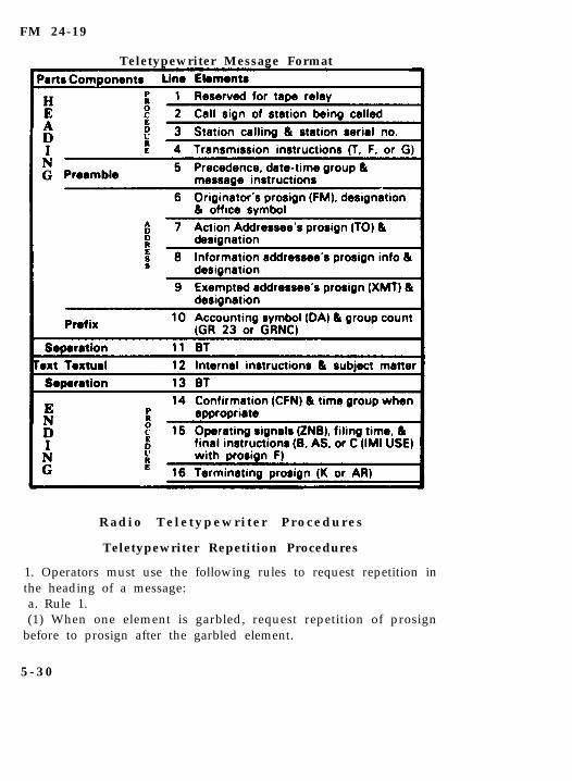
FM 24-19
Teletypewriter Message Format
R a d i o T e l e t y p e w r i t e r P r o c e d u r e s
Teletypewriter Repetition Procedures
1. Operators must use the following rules to request repetition inthe heading of a message:a. Rule 1.(1) When one element is garbled, request repetition of prosign
before to prosign after the garbled element.
5 - 3 0
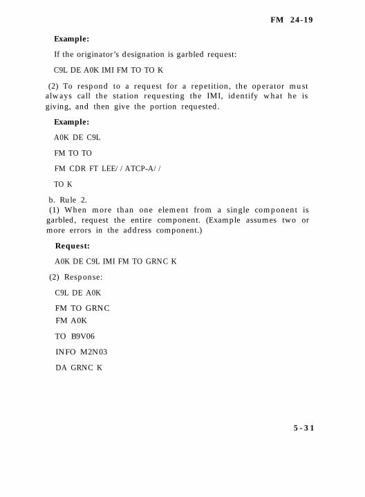
FM 24-19
Example:
If the originator’s designation is garbled request:
C9L DE A0K IMI FM TO TO K
(2) To respond to a request for a repetition, the operator mustalways call the station requesting the IMI, identify what he isgiving, and then give the portion requested.
Example:
A0K DE C9L
FM TO TO
FM CDR FT LEE//ATCP-A//
TO K
b. Rule 2.(1) When more than one element from a single component is
garbled, request the entire component. (Example assumes two ormore errors in the address component.)
Request:
A0K DE C9L IMI FM TO GRNC K
(2) Response:
C9L DE A0K
FM TO GRNC
FM A0K
TO B9V06
INFO M2N03
DA GRNC K
5 - 3 1
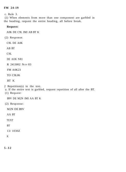
FM 24-19
c. Rule 3.(1) When elements from more than one component are garbled in
the heading, request the entire heading, all before break.
Request:
A0K DE C9L IMI AB BT K
(2) Response.
C9L DE A0K
AB BT
C9L
DE AOK NR1
R 2413002 NOV 83
FM A0K23
TO C9L06
BT K
2 Repetition(s) in the text.a. If the entire text is garbled, request repetition of all after the BT.(1) Request:
B9V DE M2N IMI AA BT K
(2) Response:
M2N DE B9V
AA BT
TEXT
BT
13/1030Z
K
5 - 3 2
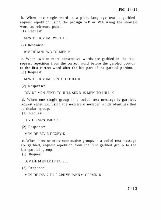
FM 24-19
b. When one single word in a plain language text is garbled,request repetition using the prosign WB or WA using the shortestword as reference point.(1) Request:
M2N DE B9V IMI WB TO K
(2) Response:
B9V DE M2N WB TO MEN K
c. When two or more consecutive words are garbled in the text,request repetition from the correct word before the garbled portionto the first correct word after the last part of the garbled portion.(1) Request:
M2N DE B9V IMI SEND TO HILL K
(2) Response:
B9V DE M2N SEND TO HILL SEND 15 MEN TO HILL K
d. When one single group in a coded text message is garbled,request repetition using the numerical number which identifies thatparticular group.(1) Request
B9V DE M2N IMI 3 K
(2) Response:
M2N DE B9V 3 DCXEY K
e. When three or more consecutive groups in a coded text messageare garbled, request repetition from the first garbled group to thelast garbled group.(1) Request:
B9V DE M2N IMI 7 TO 9 K
(2) Response:
M2N DE B9V 7 TO 9 ZBHVE IAKNM GPRMN K
5 - 3 3

FM 24-19
f. When the ending of a message is garbled, request repetition ofeverything after the last word or coded group in the text.(1) Request
(Plain language text)
M2N DE B9V IMI AA AN/FGC-25 K
(2) Response:
(Plain language text)
B9V DE M2N
AA AN/FGC-25
B T
CFN AN/FGC-25
13/1630Z
K
(3) Request:
(Coded group text)
M2N DE B9V IMI AA 6 K
(4) Response:
(Coded group text)
B9V DE M2N
AA6
B T
13/1745Z
K
5 - 3 4
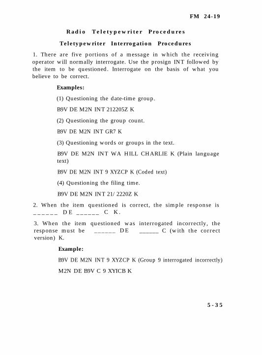
FM 24-19
R a d i o T e l e t y p e w r i t e r P r o c e d u r e s
Teletypewriter Interrogation Procedures
1. There are five portions of a message in which the receivingoperator will normally interrogate. Use the prosign INT followed bythe item to be questioned. Interrogate on the basis of what youbelieve to be correct.
Examples:
(1) Questioning the date-time group.
B9V DE M2N INT 212205Z K
(2) Questioning the group count.
B9V DE M2N INT GR7 K
(3) Questioning words or groups in the text.
B9V DE M2N INT WA HILL CHARLIE K (Plain languagetext)
B9V DE M2N INT 9 XYZCP K (Coded text)
(4) Questioning the filing time.
B9V DE M2N INT 21/2220Z K
2. When the item questioned is correct, the simple response is_ _ _ _ _ _ D E _ _ _ _ _ _ C K .
3. When the item questioned was interrogated incorrectly, theresponse must be ______ DE ______ C (with the correctversion) K.
Example:
B9V DE M2N INT 9 XYZCP K (Group 9 interrogated incorrectly)
M2N DE B9V C 9 XYICB K
5 - 3 5
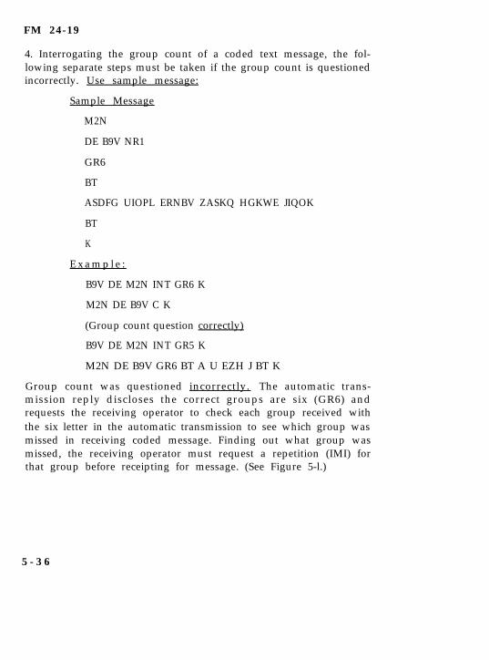
FM 24-19
4. Interrogating the group count of a coded text message, the fol-lowing separate steps must be taken if the group count is questionedincorrectly. Use sample message:
Sample Message
M2N
DE B9V NR1
GR6
BT
ASDFG UIOPL ERNBV ZASKQ HGKWE JIQOK
BT
K
E x a m p l e :
B9V DE M2N INT GR6 K
M2N DE B9V C K
(Group count question correctly)
B9V DE M2N INT GR5 K
M2N DE B9V GR6 BT A U EZH J BT K
Group count was questioned incorrectly. The automatic trans-mission reply discloses the correct groups are six (GR6) andrequests the receiving operator to check each group received withthe six letter in the automatic transmission to see which group wasmissed in receiving coded message. Finding out what group wasmissed, the receiving operator must request a repetition (IMI) forthat group before receipting for message. (See Figure 5-l.)
5 - 3 6
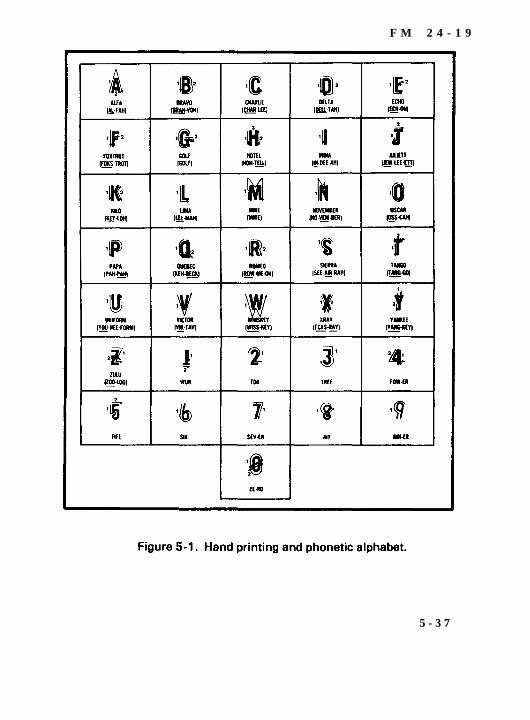
F M 2 4 - 1 9
5 - 3 7
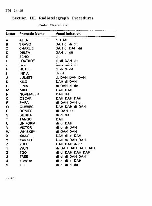
FM 24-19
Section III. Radiotelegraph Procedures
Code Characters
5 - 3 8
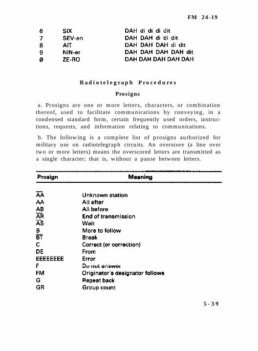
FM 24-19
R a d i o t e l e g r a p h P r o c e d u r e s
Prosigns
a. Prosigns are one or more letters, characters, or combinationthereof, used to facilitate communications by conveying, in acondensed standard form, certain frequently used orders, instruc-tions, requests, and information relating to communications.
b. The following is a complete list of prosigns authorized formilitary use on radiotelegraph circuits. An overscore (a line overtwo or more letters) means the overscored letters are transmitted asa single character; that is, without a pause between letters.
5 - 3 9
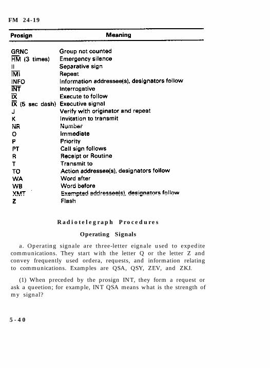
FM 24-19
R a d i o t e l e g r a p h P r o c e d u r e s
Operating Signals
a. Operating signale are three-letter eignale used to expeditecommunications. They start with the letter Q or the letter Z andconvey frequently used ordera, requests, and information relatingto communications. Examples are QSA, QSY, ZEV, and ZKJ.
(1) When preceded by the prosign INT, they form a request orask a queetion; for example, INT QSA means what is the strength ofmy signal?
5 - 4 0
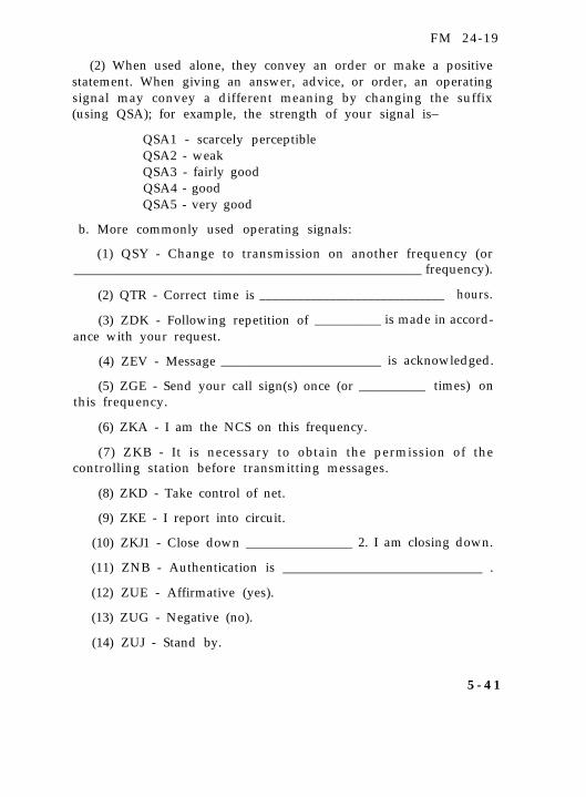
FM 24-19
(2) When used alone, they convey an order or make a positivestatement. When giving an answer, advice, or order, an operatingsignal may convey a different meaning by changing the suffix(using QSA); for example, the strength of your signal is–
QSA1 - scarcely perceptibleQSA2 - weakQSA3 - fairly goodQSA4 - goodQSA5 - very good
b. More commonly used operating signals:
(1) QSY - Change to transmission on another frequency (or____________________________________________________ frequency).
(2) QTR - Correct time is _____________________________ hours.
(3) ZDK - Following repetition of __________ is made in accord-ance with your request.
(4) ZEV - Message ________________________ is acknowledged.
(5) ZGE - Send your call sign(s) once (or __________ times) onthis frequency.
(6) ZKA - I am the NCS on this frequency.
(7) ZKB - It is necessary to obtain the permission of thecontrolling station before transmitting messages.
(8) ZKD - Take control of net.
(9) ZKE - I report into circuit.
(10) ZKJ1 - Close down ________________ 2. I am closing down.
(11) ZNB - Authentication is ______________________________ .
(12) ZUE - Affirmative (yes).
(13) ZUG - Negative (no).
(14) ZUJ - Stand by.
5 - 4 1
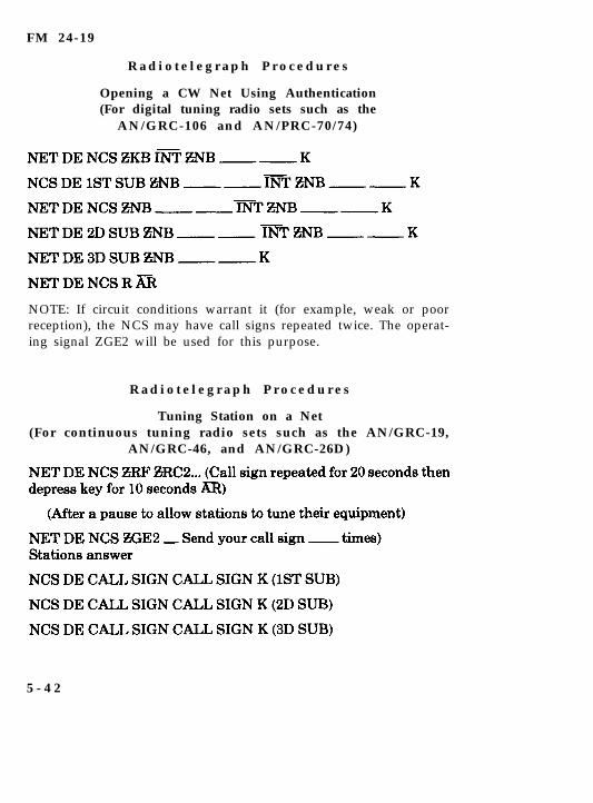
FM 24-19
R a d i o t e l e g r a p h P r o c e d u r e s
Opening a CW Net Using Authentication(For digital tuning radio sets such as the
AN/GRC-106 and AN/PRC-70/74)
NOTE: If circuit conditions warrant it (for example, weak or poorreception), the NCS may have call signs repeated twice. The operat-ing signal ZGE2 will be used for this purpose.
R a d i o t e l e g r a p h P r o c e d u r e s
Tuning Station on a Net(For continuous tuning radio sets such as the AN/GRC-19,
AN/GRC-46, and AN/GRC-26D)
5 - 4 2
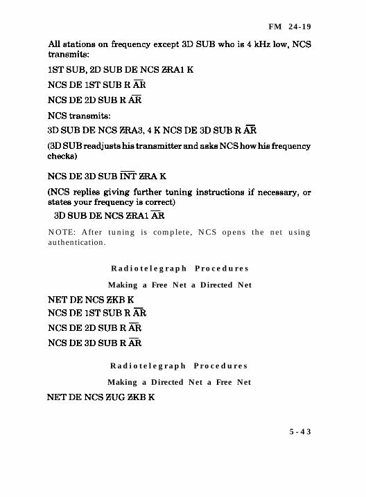
FM 24-19
NOTE: After tuning is complete, NCS opens the net usingauthentication.
R a d i o t e l e g r a p h P r o c e d u r e s
Making a Free Net a Directed Net
R a d i o t e l e g r a p h P r o c e d u r e s
Making a Directed Net a Free Net
5 - 4 3
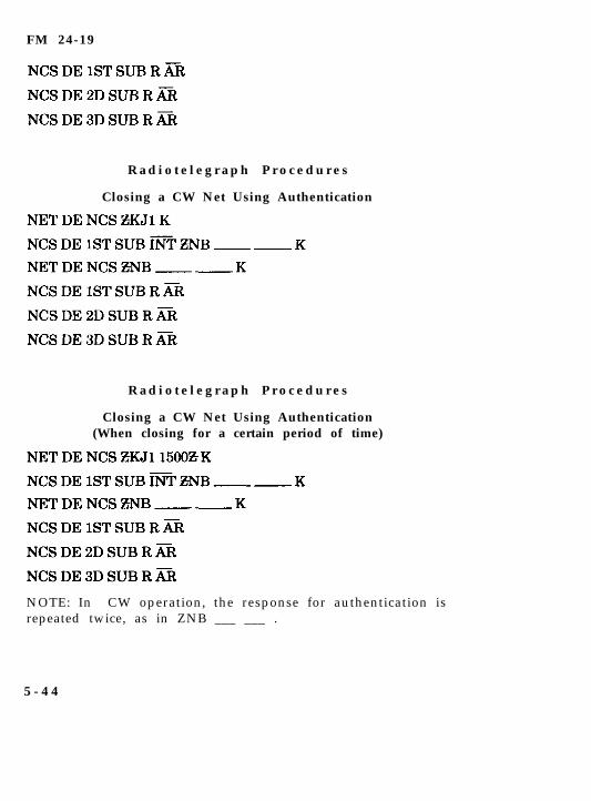
FM 24-19
R a d i o t e l e g r a p h P r o c e d u r e s
Closing a CW Net Using Authentication
R a d i o t e l e g r a p h P r o c e d u r e s
Closing a CW Net Using Authentication(When closing for a certain period of time)
NOTE: In CW operation, the response for authentication isrepeated twice, as in ZNB ___ ___ .
5 - 4 4
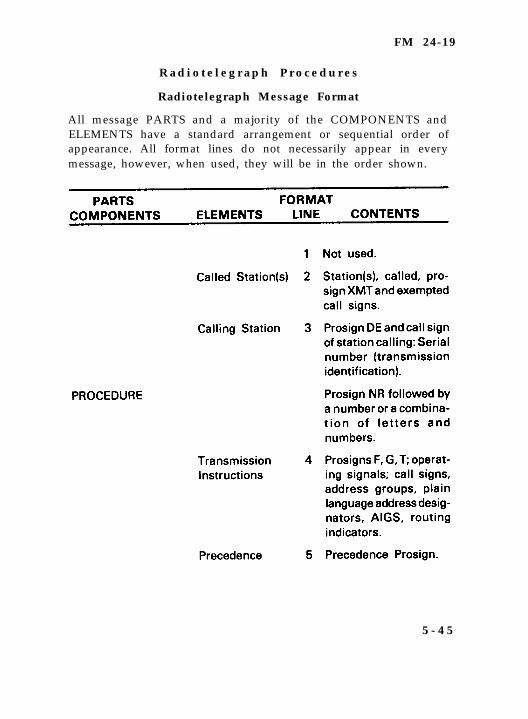
FM 24-19
R a d i o t e l e g r a p h P r o c e d u r e s
Radiotelegraph Message Format
All message PARTS and a majority of the COMPONENTS andELEMENTS have a standard arrangement or sequential order ofappearance. All format lines do not necessarily appear in everymessage, however, when used, they will be in the order shown.
5 - 4 5
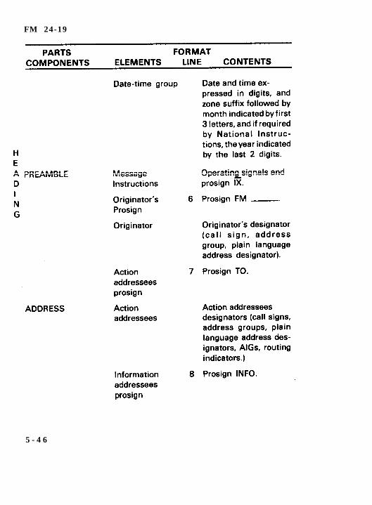
FM 24-19
5 - 4 6
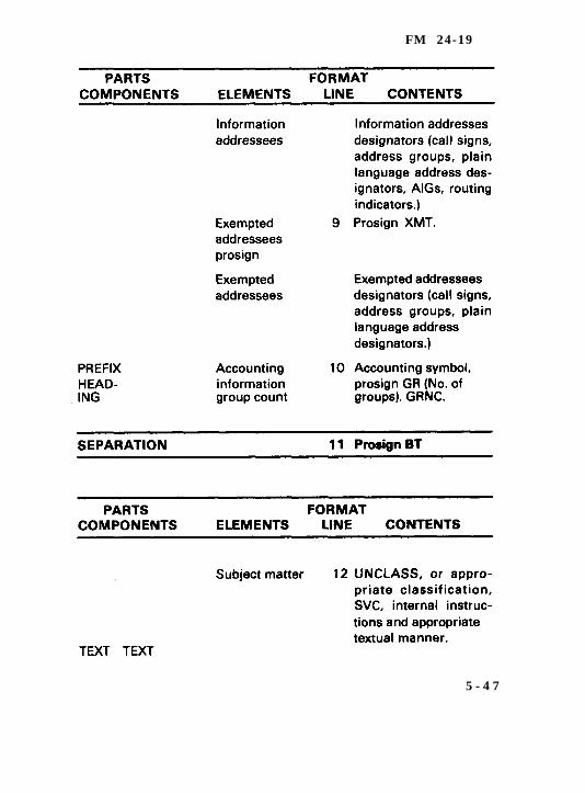
FM 24-19
5 - 4 7
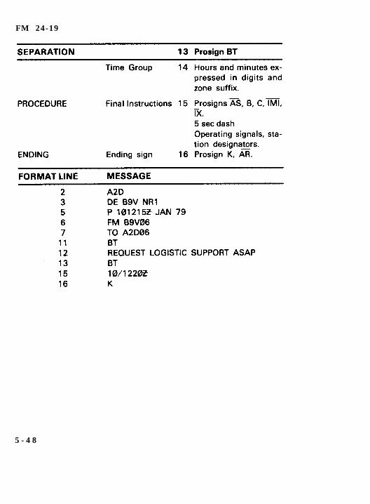
FM 24-19
5 - 4 8
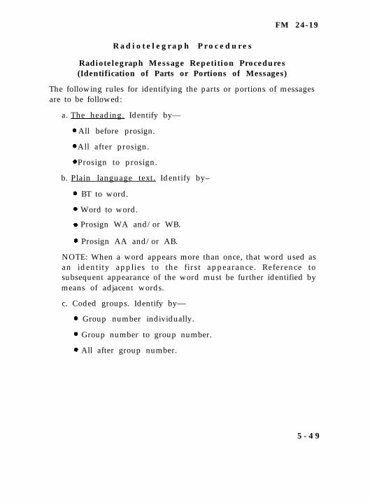
FM 24-19
R a d i o t e l e g r a p h P r o c e d u r e s
Radiotelegraph Message Repetition Procedures(Identification of Parts or Portions of Messages)
The following rules for identifying the parts or portions of messagesare to be followed:
a. The heading. Identify by—
All before prosign.
All after prosign.
Prosign to prosign.
b. Plain language text. Identify by–
BT to word.
Word to word.
Prosign WA and/or WB.
Prosign AA and/or AB.
NOTE: When a word appears more than once, that word used asan identity applies to the first appearance. Reference tosubsequent appearance of the word must be further identified bymeans of adjacent words.
c. Coded groups. Identify by—
Group number individually.
Group number to group number.
All after group number.
5 - 4 9
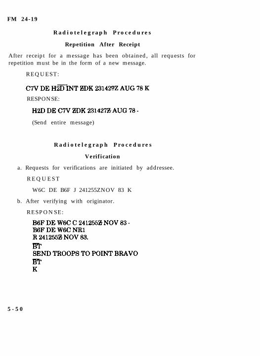
FM 24-19
R a d i o t e l e g r a p h P r o c e d u r e s
Repetition After Receipt
After receipt for a message has been obtained, all requests forrepetition must be in the form of a new message.
REQUEST:
RESPONSE:
(Send entire message)
R a d i o t e l e g r a p h P r o c e d u r e s
Verification
a. Requests for verifications are initiated by addressee.
R E Q U E S T
W6C DE B6F J 241255ZNOV 83 K
b. After verifying with originator.
RESPONSE:
5 - 5 0
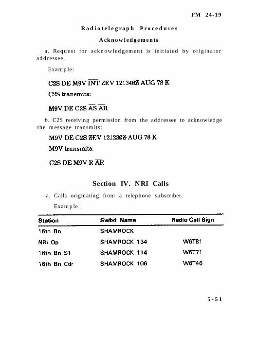
FM 24-19
R a d i o t e l e g r a p h P r o c e d u r e s
Acknowledgements
a. Request for acknowledgement is initiated by originatoraddressee.
Example:
b. C2S receiving permission from the addressee to acknowledgethe message transmits:
Section IV. NRI Calls
a. Calls originating from a telephone subscriber.
Example:
5 - 5 1
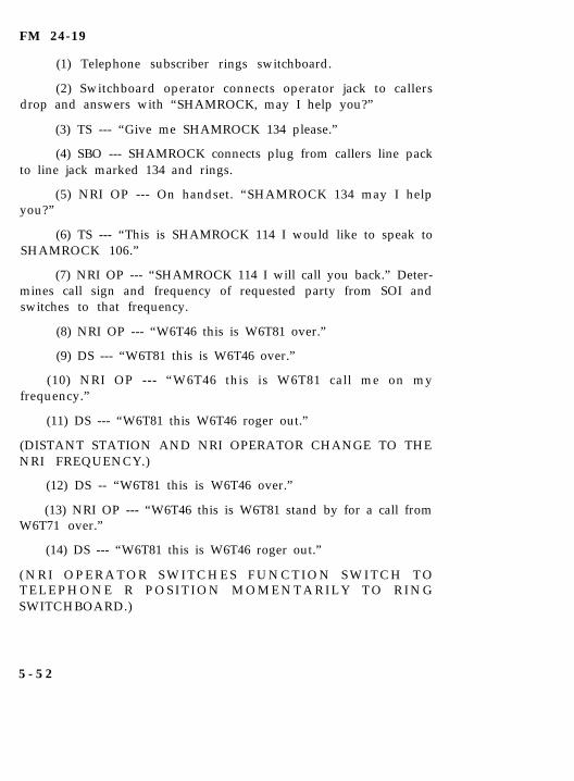
FM 24-19
(1) Telephone subscriber rings switchboard.
(2) Switchboard operator connects operator jack to callersdrop and answers with “SHAMROCK, may I help you?”
(3) TS --- “Give me SHAMROCK 134 please.”
(4) SBO --- SHAMROCK connects plug from callers line packto line jack marked 134 and rings.
(5) NRI OP --- On handset. “SHAMROCK 134 may I helpyou?”
(6) TS --- “This is SHAMROCK 114 I would like to speak toSHAMROCK 106.”
(7) NRI OP --- “SHAMROCK 114 I will call you back.” Deter-mines call sign and frequency of requested party from SOI andswitches to that frequency.
(8) NRI OP --- “W6T46 this is W6T81 over.”
(9) DS --- “W6T81 this is W6T46 over.”
(10) NRI OP --- “W6T46 this is W6T81 call me on myfrequency.”
(11) DS --- “W6T81 this W6T46 roger out.”
(DISTANT STATION AND NRI OPERATOR CHANGE TO THENRI FREQUENCY.)
(12) DS -- “W6T81 this is W6T46 over.”
(13) NRI OP --- “W6T46 this is W6T81 stand by for a call fromW6T71 over.”
(14) DS --- “W6T81 this is W6T46 roger out.”
( N R I O P E R A T O R S W I T C H E S F U N C T I O N S W I T C H T OT E L E P H O N E R P O S I T I O N M O M E N T A R I L Y T O R I N GSWITCHBOARD.)
5 - 5 2
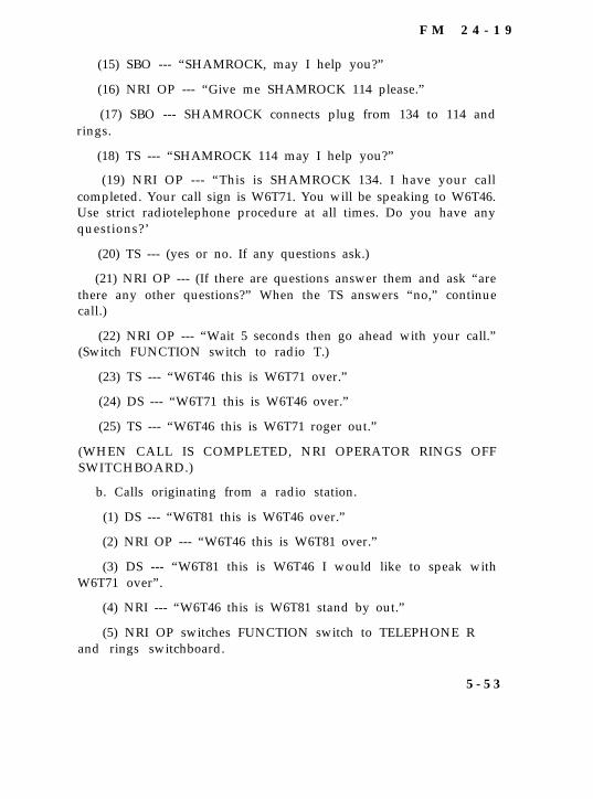
F M 2 4 - 1 9
(15) SBO --- “SHAMROCK, may I help you?”
(16) NRI OP --- “Give me SHAMROCK 114 please.”
(17) SBO --- SHAMROCK connects plug from 134 to 114 andrings.
(18) TS --- “SHAMROCK 114 may I help you?”
(19) NRI OP --- “This is SHAMROCK 134. I have your callcompleted. Your call sign is W6T71. You will be speaking to W6T46.Use strict radiotelephone procedure at all times. Do you have anyquestions?’
(20) TS --- (yes or no. If any questions ask.)
(21) NRI OP --- (If there are questions answer them and ask “arethere any other questions?” When the TS answers “no,” continuecall.)
(22) NRI OP --- “Wait 5 seconds then go ahead with your call.”(Switch FUNCTION switch to radio T.)
(23) TS --- “W6T46 this is W6T71 over.”
(24) DS --- “W6T71 this is W6T46 over.”
(25) TS --- “W6T46 this is W6T71 roger out.”
(WHEN CALL IS COMPLETED, NRI OPERATOR RINGS OFFSWITCHBOARD.)
b. Calls originating from a radio station.
(1) DS --- “W6T81 this is W6T46 over.”
(2) NRI OP --- “W6T46 this is W6T81 over.”
(3) DS --- “W6T81 this is W6T46 I would like to speak withW6T71 over”.
(4) NRI --- “W6T46 this is W6T81 stand by out.”
(5) NRI OP switches FUNCTION switch to TELEPHONE Rand rings switchboard.
5 - 5 3

FM 24-19
(6) SBO --- “SHAMROCK, may I help you?”
(7) NRI OP -- “Give me SHAMROCK 114 please.”
(8) SBO --- Connects plug from 134 to 114 and rings.
(9) TS --- “SHAMROCK 114 may I help you?”
(10) NRI OP --- “This is SHAMROCK 134. Standby for an NRIcall from SHAMROCK 106. Your call sign is W6T71. You will bespeaking to W6T46. Use strict radiotelephone procedure at alltimes. Do you have any questions? Standby please.”
(11) NRI OP --- If no questions switch FUNCTION switch toRADIO T.
(12) NRI OP --- “W6T46 this is W6T81 over.”
(13) DS --- “W6T81 this is W6T46 over.”
(14) NRI OP --- “W6T46 this is W6T81 I have your call completed.Go ahead with your call.”
(15) DS --- “W6T71 this is W6T46 over.”
(16) TS --- “W6T46 this is W6T71 over.”
(17) DS --- “W6T71 this is W6T46 out.”
(WHEN CALL IS COMPLETED, NRI OPERATOR RINGS OFFSWITCHBOARD.)
5 - 5 4
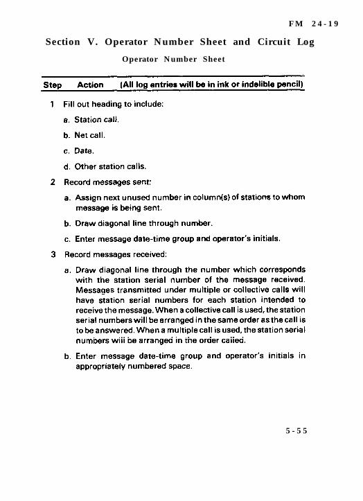
F M 2 4 - 1 9
Section V. Operator Number Sheet and Circuit Log
Operator Number Sheet
5 - 5 5
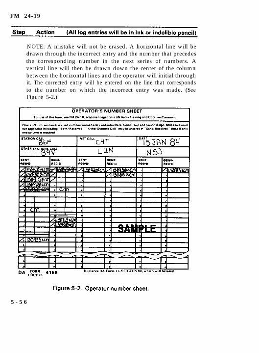
FM 24-19
NOTE: A mistake will not be erased. A horizontal line will bedrawn through the incorrect entry and the number that precedesthe corresponding number in the next series of numbers. Avertical line will then be drawn down the center of the columnbetween the horizontal lines and the operator will initial throughit. The corrected entry will be entered on the line that correspondsto the number on which the incorrect entry was made. (SeeFigure 5-2.)
5 - 5 6
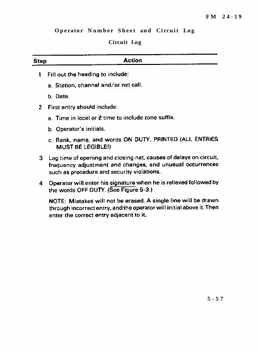
F M 2 4 - 1 9
Operator Number Sheet and Circuit Log
Circuit Log
5 - 5 7
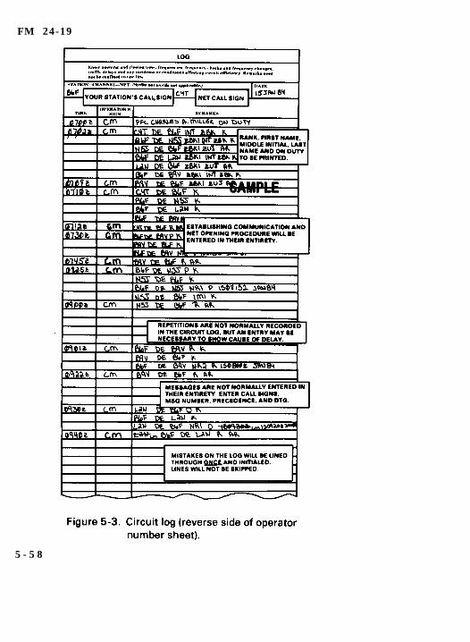
FM 24-19
5 - 5 8
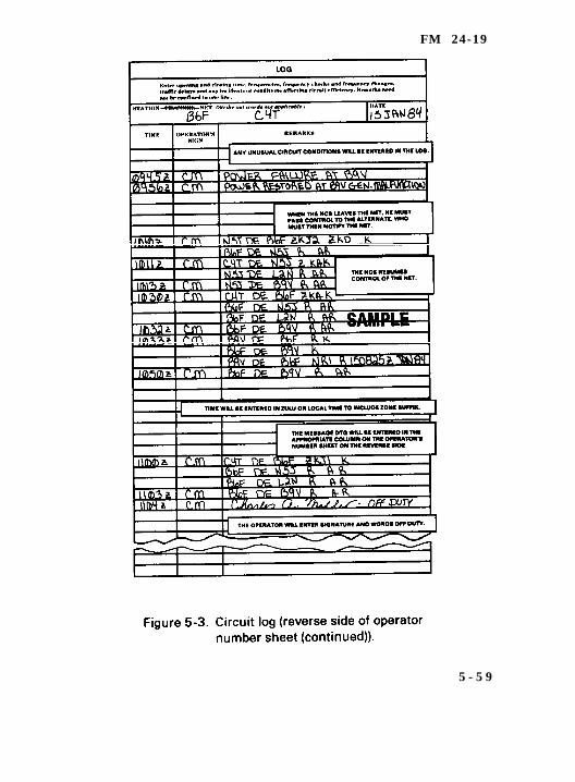
FM 24-19
5 - 5 9
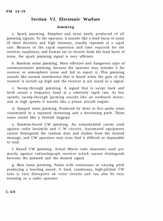
FM 24-19
Section VI. Electronic Warfare
Jamming
a. Spark jamming. Simplest and most easily produced of alljamming signals. To the operator, it sounds like a loud burst of noiseof short duration and high intensity, usually repeated at a rapidrate. Because of the rapid repetition and time required for thereceiver, earphones, and human ear to recover from the loud burst ofnoise, the spark jamming signal is very efficient.
b. Random noise jamming. Most effective and dangerous type ofcommunications jamming, because the operator may mistake it forreceiver or atmospheric noise and fail to report it. This jammingsounds like normal interference that is heard when the gain of thereceiver is turned up high and the receiver is not tuned to a signal.
c. Sweep-through jamming. A signal that is swept back andforth across a frequency band at a relatively rapid rate. At lowspeeds, sweep-through jqvming sounds like an outboard motor,and at high speeds it sounds like a piston aircraft engine.
d. Stepped tones jamming. Produced by three to five audio tonestransmitted in a repeated increasing and a decreasing pitch. Thesetones sound like a Scottish bagpipe.
e. Random-keyed CW jamming. An unmodulated carrier usedagainst radio facsimile and C W circuits. Automated equipmentcannot distinguish the random dote and dashes from the desiredmessage, and CW operators may even find it difficult or impossibleto read.
f. Keyed CW jamming. Actual Morse code characters used pri-marily against radiotelegraph receiver which cannot distinguishbetween the jammed and the desired signal.
g. Beat tones jamming. Notes with continuous or varying pitchproducing a howling sound. A loud, continuous, high-pitched CWtone is very disruptive on voice circuits and can also be veryirritating to a radio operator.
5 - 6 0
FM 24-19
h. Babbled-voice jamming. One form, called cocktail party,sounds like a crowd of people all talking at the same time. If thejamming signal’s strength is greater than the desired message, itmakes reception very difficult.
i. Recorded music jamming. May also be used to jam voicesignals. This type of jamming may appear to be an ordinarybroadcast being received on a harmonic to conceal the fact that it isdeliberate.
E l e c t r o n i c W a r f a r e
Implementing ECCM Procedures
1. Disconnect the receiving antenna to ensure the interference iscoming from an external source. Electrical generators, overheadpower lines and friendly equipment located nearby should bestudied as possible causes of interference.
2. Follow antijamming (ECCM) measures:
a. Notify your immediate supervisor of suspected jamming. DONOT INDICATE THAT YOU ARE BEING JAMMED OVER THERADIO.
b. Reduce transmission speed (CW).
c. Remain calm and continue to operate.
d. Observe radio/net discipline.
e. Adjust fine tuning, gain (or volume) control, bandwidthselector, crystal filter and/or other controls peculiar to the equip-ment being used.
f. Increase transmitter power.
g. Reorient or resite your antenna or change antenna polar-ization.
h. Impose obstacles between your station antenna and thesource of the jamming signals.
5 - 6 1
FM 24-19
E l e c t r o n i c W a r f a r e
MIJI Reporting
The radio operator must report all interference, whether jam-ming or natural interference, immediately to his communicationssupervisor. Any attempted or successful enemy deception should bereported immediately. The communications supervisor will sendthe report to higher headquarters for action. Jamming informationshould be recorded on the circuit log sheet to facilitate reporting.Information on jamming should be reported in the followingformat:
a. Initial MIJIFEEDER report. This is an abbreviated reportcontaining only those items of information necessary to informheadquarters of the incident. The MIJIFEEDER report issubmitted using the USMTF (JINTACCS) voice template (Figures5-4 and 5-5). The MIJI report should be forwarded using the mostsecure means available. When transmitted over a nonsecure net,the report must be encrypted before transmittal.
(1) Line 1- Unit Identification.
(2) Line 2- Type of Interference.
(3) Line 3- Location (Latitude/Longitude or UTM (GridCoordinates)).
(4) Line 4- Start Day-Time-Zone.
(5) Line 5- End Day-Time-Zone.
(6) Line 6- Operations/Equipment Affected.
(7) Line 7- Frequency/Frequency Range.
(8) Line 8- Narrative.
(9) Line 9- Message Hour-Minute-Zone (When Required).
(10) Line 10- Message Authentication IAW JTF Procedures.
5 - 6 2
FM 24-19
b. The MIJIFEEDER record message report (MFRMR). This is acomplete report of all the details of the incident. Due to the numberof items that must be encrypted when the report is transmitted overa nonsecure circuit, the report should be delivered by messengerwhenever possible. Either the operations officer, intelligenceofficer, or the electronic warfare officer is responsible for ensuringthat a complete message report of the incident is submitted to theJoint Electronic Warfare Center (JEWC) as soon as possible follow-ing the incident.
c. Reference material. Refer to AR 105-3, FM 24-33, and FM24-35-1 for a more detailed treatment of MIJIFEEDER andMIJIFEEDER record message reports.
5 - 6 3
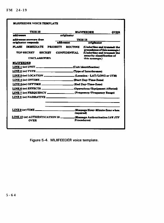
F M 2 4 - 1 9
5 - 6 4
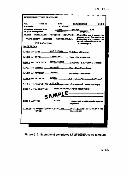
FM 24-19
5 - 6 5
FM 24-19
Section VII. Using the SOI
Encode and Decode Messages Using KTC-600Tactical Operations Code
1. Encode messages (refer to SOI and KTC-600).
a. Write messages in plain text.
b. Turn to set page and locate set number for effective day.
c. Turn to encode page for effective set.
d. Locate word or phrase to be encoded.
NOTE: Words and phrases located alphabetically.
e. Identify the three letter code group located to left of word orphrase.
f. Write code group under applicable word or phrase untilmessage is encoded.
2. Decode messages (refer to SOI and KTC-600).
a. Write down encoded messages.
b. Turn to decode page in effect for that day.
c. Locate code groups and write the word or phrase beneathapplicable group.
Using the SOI
Encrypt/Decrypt Numbers and Grid Zones
For detailed instructions on encrypting/decrypting, see SOIKAV 1600 Supplement 2.
5 - 6 6
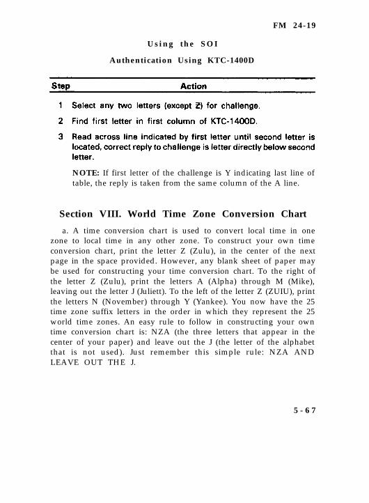
FM 24-19
Using the SOI
Authentication Using KTC-1400D
NOTE: If first letter of the challenge is Y indicating last line oftable, the reply is taken from the same column of the A line.
Section VIII. World Time Zone Conversion Chart
a. A time conversion chart is used to convert local time in onezone to local time in any other zone. To construct your own timeconversion chart, print the letter Z (Zulu), in the center of the nextpage in the space provided. However, any blank sheet of paper maybe used for constructing your time conversion chart. To the right ofthe letter Z (Zulu), print the letters A (Alpha) through M (Mike),leaving out the letter J (Juliett). To the left of the letter Z (ZUIU), printthe letters N (November) through Y (Yankee). You now have the 25time zone suffix letters in the order in which they represent the 25world time zones. An easy rule to follow in constructing your owntime conversion chart is: NZA (the three letters that appear in thecenter of your paper) and leave out the J (the letter of the alphabetthat is not used). Just remember this simple rule: NZA ANDLEAVE OUT THE J.
5 - 6 7
FM 24-19
b. When using your time conversion chart, there are two easyrules to follow: First, you NEVER count the time zone in which youare located. Second, you add 1 hour for each time zone crossed whenmoving to your right, and you subtract 1 hour for each time zonecrossed when moving to your left. In more simple terms, ADD whengoing to the RIGHT and SUBTRACT when going to the LEFT. Forexample, if you were stationed in C (Charlie) time zone and neededto convert to Z (Zulu) time, you would start with the letter C. Do notcount the C for this is the zone in which you are stationed. Thencount the B, A and Z zones to your left (three) and subtract 3 hoursfrom your local time, and the result will be GCT or Z (ZUIU) time. (SeeFigure 5-6.)
Section IX. United States Message Text Format
a. The USMTF (JINTACCS) Program provides a series of stan-dard message formats for six discrete mission area segments. Thesesegments are operations control, fire support air operations,intelligence, maritime operations, and combat service support. Themajor USMTF (JINTACCS) product line consists of the following:
Standardized voice message text formats.
Standardized record MTFs.
Standardized tactical digital information link messageformats.
Standardized interface operating procedures.
Central data base system.
b. Voice messages are designed for ease of preparation andtransmission. Operators fill in the appropriate blanks on theappropriate message template and then read the message over theradio or telephone. The receiver, knowing the format, can easilyrecord the information. Voice messages are normally used whenrecord traffic devices are inoperative or not available, or when thetactical situation does not allow adequate time for operators toformat a record message.
5 - 6 8

F M 2 4 - 1 9
5 - 6 9
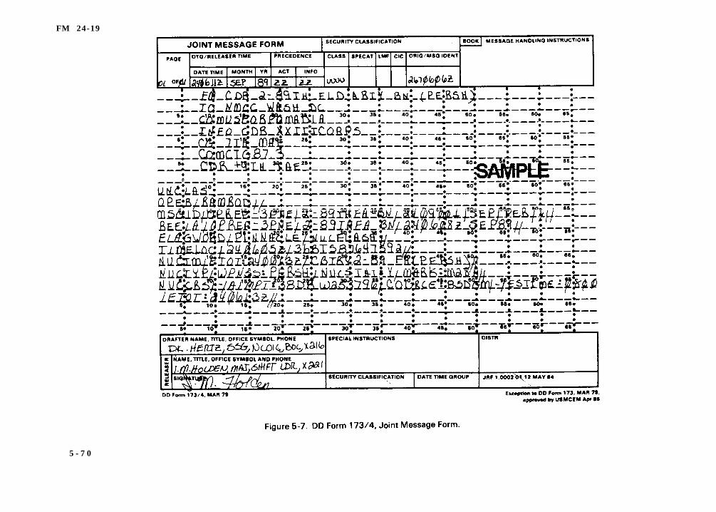
FM 24-19
5 - 7 0

F M 2 4 - 1 9
c. Record messages are designed to be processed and trans-mitted by teletype, subscriber terminals, or computer terminalsdevices. Figure 5-7 shows a sample joint message form. They can beread manually and are machine (computer) processed. Machinep r o c e s s i b i l i t y i s a n i m p o r t a n t c h a r a c t e r i s t i c o f t h eUSMTF (JINTACCS) record message because it minimizes humanintervention.
5 - 7 1
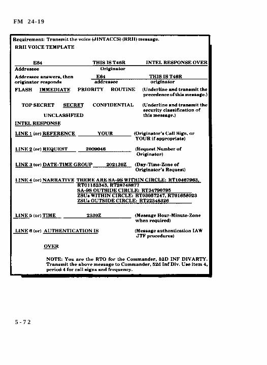
FM 24-19
5 - 7 2
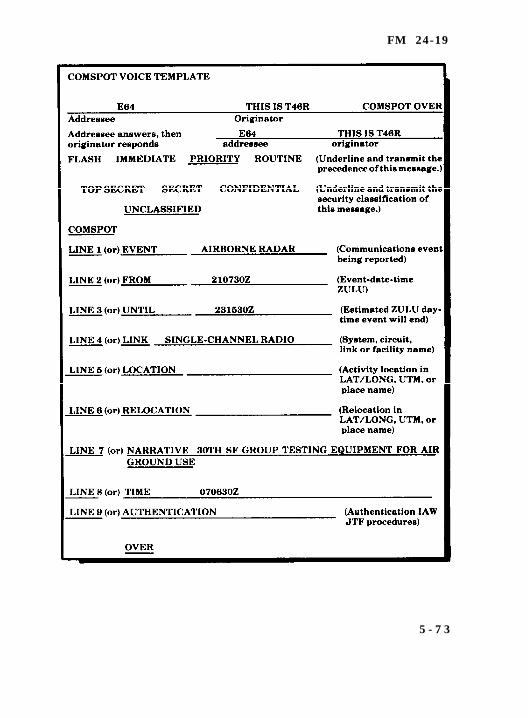
FM 24-19
5 - 7 3

FM 24-19
AC
adj
A F
A F C
AGC
A L C
AM
amp
a n t
A S A P
aud
auto
a u x
bal
b a t
bde
B F O
b k r
b l o / b l w r
bn
B N C
Glossary-0
Glossary
Acronyms and Abbreviations
alternating current
adjust
audio frequency
automatic frequency control
automatic gain control
automatic level control
amplitude modulated
ampere
antenna
as soon as possible
audio
automatic
auxiliary
balance
battery
brigade
beat frequency oscillator
breaker
blower
battalion
British National Council (connector)
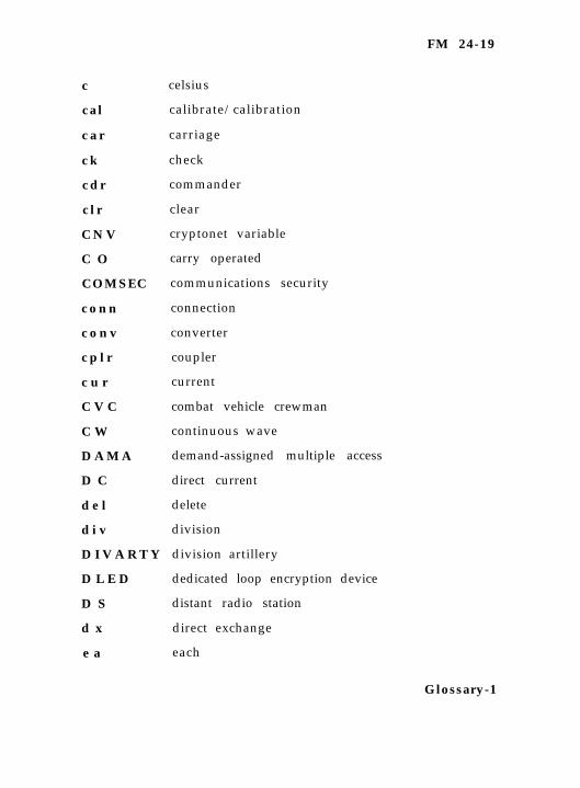
FM 24-19
c
c a l
c a r
c k
c d r
c l r
C N V
C O
COMSEC
c o n n
c o n v
c p l r
c u r
C V C
C W
D A M A
D C
d e l
d i v
D I V A R T Y
D L E D
D S
d x
e a
celsius
calibrate/calibration
carriage
check
commander
clear
cryptonet variable
carry operated
communications security
connection
converter
coupler
current
combat vehicle crewman
continuous wave
demand-assigned multiple access
direct current
delete
division
division artillery
dedicated loop encryption device
distant radio station
direct exchange
each
Glossary-1

FM 24-19
ECCM
E P C
e x t
F
fil
FM
freq
F S K
ft
fwd
gen
gnd
H A E M P
HCM
H F
HV
Hz
IAW
I C T
I F
I H F R
i n f
info
int
Glossary-2
electronic counter-countermeasures
equipment performance check
external
Fahrenheit
filter
frequency modulated
frequency
frequency shift keying
feet
forward
generator
ground
high altitude electromagnetic pulse-protected
higher category of maintenance
high frequency
high voltage
hertz
in accordance with
intelligence communications terminal
intermediate frequency
improved high frequency radio
infantry
information
internal
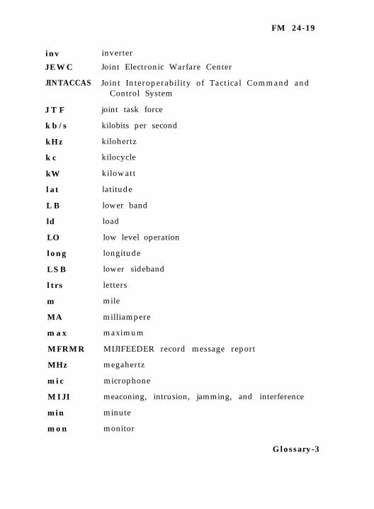
FM 24-19
inv inverter
J E W C Joint Electronic Warfare Center
Joint Interoperability of Tactical Command andJINTACCAS
J T F
k b / s
kHz
k c
kW
l a t
L B
ld
LO
long
L S B
l t r s
m
MA
m a x
MFRMR
MHz
m i c
M I J I
min
m o n
Control System
joint task force
kilobits per second
kilohertz
kilocycle
kilowatt
latitude
lower band
load
low level operation
longitude
lower sideband
letters
mile
milliampere
maximum
MIJIFEEDER record message report
megahertz
microphone
meaconing, intrusion, jamming, and interference
minute
monitor
Glossary-3
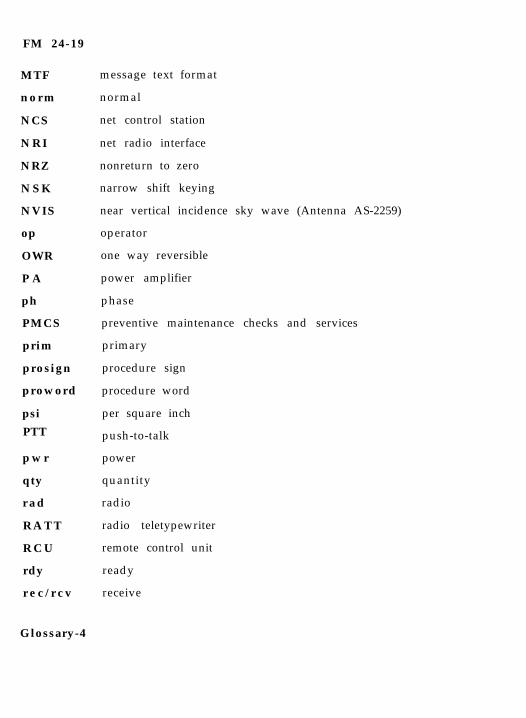
FM 24-19
MTF
n o r m
NCS
N R I
NRZ
N S K
NVIS
op
OWR
P A
ph
PMCS
prim
prosign
proword
psi
PTT
p w r
qty
r a d
R A T T
R C U
rdy
r e c / r c v
message text format
normal
net control station
net radio interface
nonreturn to zero
narrow shift keying
near vertical incidence sky wave (Antenna AS-2259)
operator
one way reversible
power amplifier
phase
preventive maintenance checks and services
primary
procedure sign
procedure word
per square inch
push-to-talk
power
quantity
radio
radio teletypewriter
remote control unit
ready
receive
Glossary-4
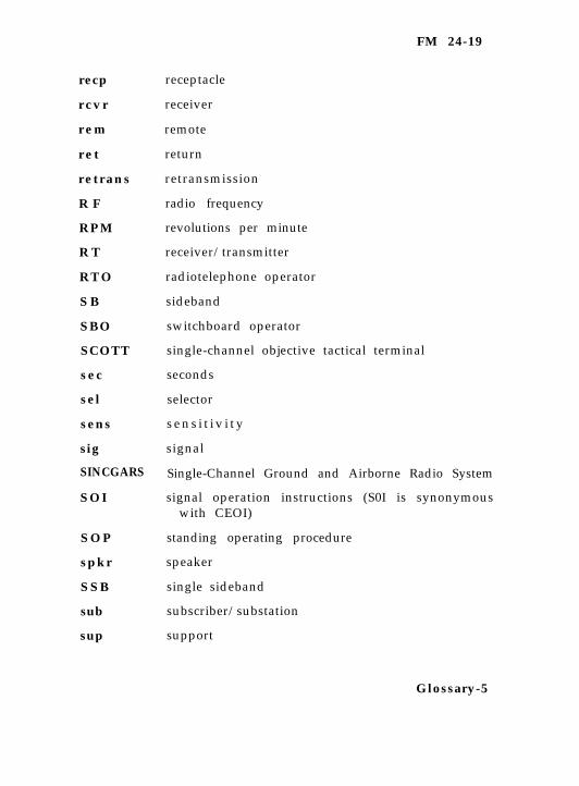
FM 24-19
recp
r c v r
r e m
r e t
r e t r a n s
R F
R P M
R T
R T O
S B
SBO
SCOTT
s e c
sel
sens
sig
receptacle
receiver
remote
return
retransmission
radio frequency
revolutions per minute
receiver/transmitter
radiotelephone operator
sideband
switchboard operator
single-channel objective tactical terminal
seconds
selector
s e n s i t i v i t y
signal
SINCGARS Single-Channel Ground and Airborne Radio System
SOI signal operation instructions (S0I is synonymouswith CEOI)
S O P standing operating procedure
spkr speaker
S S B single sideband
sub subscriber/substation
sup support
Glossary-5

FM 24-19
T R A N S E C
s w switch
swbd switchboard
SWR standing wave ratio
TD transmitter distributor
tel telephone
TM technical manual
TDMA time-division multiple access
transmission security
T S telephone subscriber
T T Y teletypewriter
tun tune
U C I D user controlled interface device
unclas unclassified
U S B upper sideband
UTM Universal Transverse Mercator
USMTF United States Message Text Format
Glossary-6

FM 24-19
v volt
V F O voice frequency oscillator
V H F very high frequency
vis visual
V O X voice operated keying
VSWR voltage standing wave ratio
WPM words per minute
xmt/xmit/ transmitt r
x t a l crystal
ZRO zero
Glossary-7
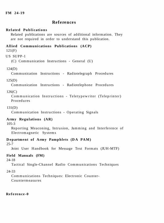
FM 24-19
References
Related PublicationsRelated publications are sources of additional information. Theyare not required in order to understand this publication.
Allied Communications Publications (ACP)121(F)
US SUPP-1(C) Communication Instructions - General (U)
124(D)Communication Instructions - Radiotelegraph Procedures
125(D)Communication Instructions - Radiotelephone Procedures
126(C)Communication Instructions - Teletypewriter (Teleprinter)Procedures
131(D)Communication Instructions - Operating Signals
Army Regulations (AR)105-3
Reporting Meaconing, Intrusion, Jamming and Interference ofElectromagnetic Systems
Department of Army Pamphlets (DA PAM)25-7
Joint User Handbook for Message Text Formats (JUH-MTF)
Field Manuals (FM)24-18
Tactical Single-Channel Radio Communications Techniques
24-33Communications Techniques: Electronic Counter-Countermeasures
Reference-0
FM 24-19
24-35-1Signal Supplemental Instructions
F o r m sDA Form
2404Equipment Inspection and Maintenance Worksheet
DD Form173/4Joint Message Form
Technical Bulletins (TB)43-0125
Installation of Communications-Electronic Equipment Hook-up of Electrical Cables to Mobile Generator Sets on FieldedEquipment to Meet Electrical Safety Standards
Training Circulars (TC)11-6
Grounding Techniques
Technical Manuals (TM)11-5805-201-12
Operator’s and Organizational Maintenance Manual for Tele-phone Set, TA-312/PT and TA-312A/PT
11-5805-387-15-1Operator’s, Organizational, Direct Support, General Support,and Depot Maintenance Manual: Modem, Radio TeletypewriterMD-522\GRC
11-5805-387-15-2Operator’s, Organizational, Direct Support, General Support,and Depot Maintenance Manual: Radio Teletypewriter Modem,MD-522A/GRC
Reference-1
FM 24-19
11-5815-200-12Operator ’s and Organizat ional Maintenance Manual :Teletypewriter Sets, AN/FGC-20, AN/FGC-20X, AN/FGC-21,AN/FGC-66, AN/FGC-159 and AN/FGC-159X, AN/FGC-160,AN/FGC-177, AN/UGC-4, AN/UGC-29, AN/UGC-29X andTeleprinter, TT-259/FG
11-5815-204-10Operator’s Manual: Radio Teletypewriter Sets, AN/GRC-46and AN/GRC-46A, AN/GRC-46B, AN/GRC-46C and AN/VRC-29
11-5815-238-10Operator’s Manual for Teletypewriter Sets, AN/GGC-3,AN/GGC-3A, AN/GGC-53, AN/GGC-53A, and TeletypewriterReperforator-Transmit ters , TT-76/GGC, TT-76A/GGC,TT-76B/GGC and TT-76C/GGC, TT-699/GGC, TT-699A/GGC,TT-699B/GGC and TT-699C/GGC
11-5815-331-14Operator’s, Organizational, Direct Support, and GeneralSupport Maintenance Manual: Radio Teletypewriter SetAN/VSC-2 and AN/VSC-2A
11-5815-332-15Operator’s, Organizational, Direct Support, General Support,and Depot Maintenance Manual: Radio Teletypewriter Set,AN/VSC-3
11-5815-334-10Operator’s Manual for Radio Teletypewriter Sets, AN/GRC-122,AN/GRC-122A, AN/GRC-122B, AN/GRC-122C, AN/GRC-122D, AN/GRC-122E, AN/GRC-142, AN/GRC-142A, AN/GRC-142B, AN/GRC-142C, AN/GRC-142D and AN/GRC-142E
11-5815-602-10Operator’s Manual for Terminal, Communications, AN/UGC-74A(V)3
Reference-2
FM 24-19
11-5815-616-13Operator’s Organizational and Direct Support MaintenanceManual Installation Kit, Electronics Equipment MK-2488/G
11-5820-489-10Operator’s Manual for Control Group, AN/GRA-6
11-5820-489-34Direct Support and General Support Maintenance Manual,Control Group AN/GRA-6
11-5820-520-10Operator’s Manual for Radio Sets, AN/GRC-106 and AN/GRC-106A
11-5820-520-20Organizational Maintenance Manual for Radio Sets, AN/GRC-106 and AN/GRC-106A
11-5820-919-12Operator’s and Organizational Maintenance Manual for RadioSet, AN/PRC-104A
11-5820-923-12Operator’s and Organizational Maintenance Manual for RadioSet, AN/GRC-213
11-5820-924-13Operator’s, Organizational and Direct Support MaintenanceManual for Radio Set, AN/GRC-193A
11-5985-357-13Operator’s, Organizational, and Direct Support MaintenanceManual for Antenna Group, OE-254/GRC
Reference-3
FM 24-1924 MAY 1991
By Order of the Secretary of the Army:
CARL E. VUONOGeneral, United States Army
Chief of Staff
Official:
PATRICIA P. HICKERSONColonel, United States Army
The Adjutant General
DISTRIBUTION:
Active Army, USAR, and ARNG: To be distributed in ac-cordance with DA Form 12-11E, requirements for FM24-19, Radio Operator’s Handbook (Qty rqr block no.1343).
✩ U.S. GOVERNMENT PRINTING OFFICE : 1994 0 - 300-421 (82875)

PIN: 033195-000