Embed Size (px)
Citation preview
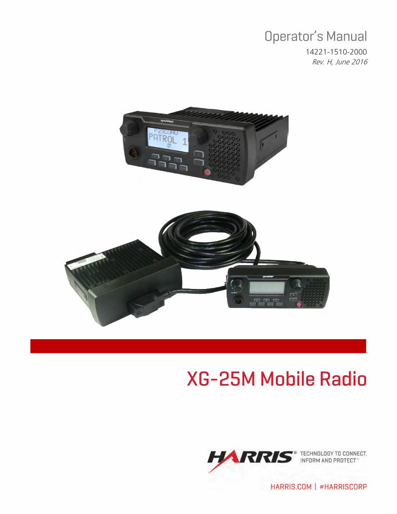
14221-1510-2000, Rev. H
2
MANUAL REVISION HISTORY
REV. DATE REASON FOR CHANGE
D Oct/14 Updated for XGP R4A; added Voice Annunciation. Added UHF antennas. Added CE information.
E Feb/15 Added OpenSky® operation.
F Apr/15 Updated for XGP R5A.
G Nov/15 Added VHF CE information.
H Jun/16 Revised manual front and rear pages.
ACKNOWLEDGEMENT This device is made under license under one or more of the following US patents: 4,590,473; 4,636,791; 5,148,482; 5,185,796; 5,271,017; 5,377,229; 4,716,407; 4,972,460; 5,502,767; 5,146,497; 5,164,986; 5,185,795; 5,226,084; 5,247,579; 5,491,772; 5,517,511; 5,630,011; 5,649,050; 5,701,390; 5,715,365; 5,754,974; 5,826,222; 5,870,405; 6,161,089; and 6,199,037 B1. DVSI claims certain rights, including patent rights under aforementioned U.S. patents, and under other U.S. and foreign patents and patents pending. Any use of this software or technology requires a separate written license from DVSI.
CREDITS Harris, OpenSky, and EDACS are registered trademarks and ProVoice, ProScan, TECHNOLOGY TO CONNECT, INFORM AND PROTECT, and ProFile are trademarks of Harris Corporation. AMBE is a registered trademark and IMBE, AMBE+, and AMBE+2 are trademarks of Digital Voice Systems, Inc. Bluetooth is a registered trademark of Bluetooth SIG, Inc. All other brand and product names are trademarks, registered trademarks, or service marks of their respective holders. Windows is a registered trademark of Microsoft, Corp. Motorola is a registered trademark of Motorola, Inc.
NOTICE! The material contained herein is subject to U.S. export approval. No export or re-export is permitted without written approval from the U.S. Government. Rated: EAR99 in accordance with U.S. Dept. of Commerce regulations 15CFR774, Export Administration Regulations. Information and descriptions contained herein are the property of Harris Corporation. Such information and descriptions may not be copied or reproduced by any means, or disseminated or distributed without the express prior written permission of Harris Corporation, PSPC Business, 221 Jefferson Ridge Parkway, Lynchburg, VA 24501. The voice coding technology embodied in this product is protected by intellectual property rights including patent rights, copyrights, and trade secrets of Digital Voice Systems, Inc. The user of this technology is explicitly prohibited from attempting to decompile, reverse engineer, or disassemble the Object Code, or in any other way convert the Object Code into human-readable form. Repairs to this equipment should be made only by an authorized service technician or facility designated by the supplier. Any repairs, alterations or substitutions of recommended parts made by the user to this equipment not approved by the manufacturer could void the user's authority to operate the equipment in addition to the manufacturer's warranty.
This product conforms to the European Union WEEE Directive 2012/19/EU. Do not dispose of this product in a public landfill. Take it to a recycling center at the end of its life.
Harris products comply with the Restriction of the Use of Certain Hazardous Substances in Electrical and Electronic Equipment (RoHS) Directive.
This manual is published by Harris Corporation without any warranty. Improvements and changes to this manual necessitated by typographical errors, inaccuracies of current information, or improvements to programs and/or equipment, may be made by Harris Corporation at any time and without notice. Such changes will be incorporated into new editions of this manual. No part of this manual may be reproduced or transmitted in any form or by any means, electronic or mechanical, including photocopying and recording, for any purpose, without the express written permission of Harris Corporation. Copyright© 2012 - 2016, Harris Corporation
14221-1510-2000, Rev. H
3
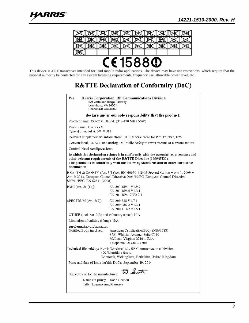
This device is a RF transceiver intended for land mobile radio applications. The device may have use restrictions, which require that the national authority be contacted for any system licensing requirements, frequency use, allowable power level, etc.
14221-1510-2000, Rev. H
4
14221-1510-2000, Rev. H
5
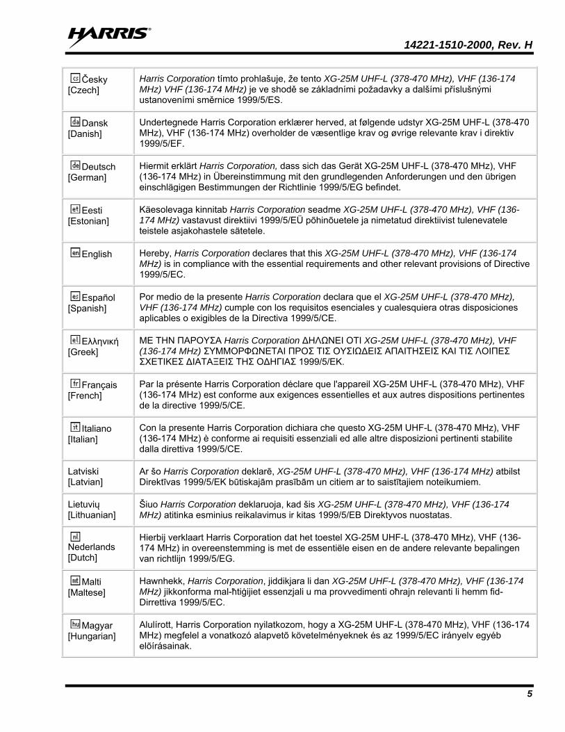
Česky [Czech]
Harris Corporation tímto prohlašuje, že tento XG-25M UHF-L (378-470 MHz), VHF (136-174 MHz) VHF (136-174 MHz) je ve shodě se základními požadavky a dalšími příslušnými ustanoveními směrnice 1999/5/ES.
Dansk [Danish]
Undertegnede Harris Corporation erklærer herved, at følgende udstyr XG-25M UHF-L (378-470 MHz), VHF (136-174 MHz) overholder de væsentlige krav og øvrige relevante krav i direktiv 1999/5/EF.
Deutsch [German]
Hiermit erklärt Harris Corporation, dass sich das Gerät XG-25M UHF-L (378-470 MHz), VHF (136-174 MHz) in Übereinstimmung mit den grundlegenden Anforderungen und den übrigen einschlägigen Bestimmungen der Richtlinie 1999/5/EG befindet.
Eesti [Estonian]
Käesolevaga kinnitab Harris Corporation seadme XG-25M UHF-L (378-470 MHz), VHF (136-174 MHz) vastavust direktiivi 1999/5/EÜ põhinõuetele ja nimetatud direktiivist tulenevatele teistele asjakohastele sätetele.
English Hereby, Harris Corporation declares that this XG-25M UHF-L (378-470 MHz), VHF (136-174 MHz) is in compliance with the essential requirements and other relevant provisions of Directive 1999/5/EC.
Español [Spanish]
Por medio de la presente Harris Corporation declara que el XG-25M UHF-L (378-470 MHz), VHF (136-174 MHz) cumple con los requisitos esenciales y cualesquiera otras disposiciones aplicables o exigibles de la Directiva 1999/5/CE.
Ελληνική [Greek]
ΜΕ ΤΗΝ ΠΑΡΟΥΣΑ Harris Corporation ΔΗΛΩΝΕΙ ΟΤΙ XG-25M UHF-L (378-470 MHz), VHF (136-174 MHz) ΣΥΜΜΟΡΦΩΝΕΤΑΙ ΠΡΟΣ ΤΙΣ ΟΥΣΙΩΔΕΙΣ ΑΠΑΙΤΗΣΕΙΣ ΚΑΙ ΤΙΣ ΛΟΙΠΕΣ ΣΧΕΤΙΚΕΣ ΔΙΑΤΑΞΕΙΣ ΤΗΣ ΟΔΗΓΙΑΣ 1999/5/ΕΚ.
Français [French]
Par la présente Harris Corporation déclare que l'appareil XG-25M UHF-L (378-470 MHz), VHF (136-174 MHz) est conforme aux exigences essentielles et aux autres dispositions pertinentes de la directive 1999/5/CE.
Italiano [Italian]
Con la presente Harris Corporation dichiara che questo XG-25M UHF-L (378-470 MHz), VHF (136-174 MHz) è conforme ai requisiti essenziali ed alle altre disposizioni pertinenti stabilite dalla direttiva 1999/5/CE.
Latviski [Latvian]
Ar šo Harris Corporation deklarē, XG-25M UHF-L (378-470 MHz), VHF (136-174 MHz) atbilst Direktīvas 1999/5/EK būtiskajām prasībām un citiem ar to saistītajiem noteikumiem.
Lietuvių [Lithuanian]
Šiuo Harris Corporation deklaruoja, kad šis XG-25M UHF-L (378-470 MHz), VHF (136-174 MHz) atitinka esminius reikalavimus ir kitas 1999/5/EB Direktyvos nuostatas.
Nederlands [Dutch]
Hierbij verklaart Harris Corporation dat het toestel XG-25M UHF-L (378-470 MHz), VHF (136-174 MHz) in overeenstemming is met de essentiële eisen en de andere relevante bepalingen van richtlijn 1999/5/EG.
Malti [Maltese]
Hawnhekk, Harris Corporation, jiddikjara li dan XG-25M UHF-L (378-470 MHz), VHF (136-174 MHz) jikkonforma mal-ħtiġijiet essenzjali u ma provvedimenti oħrajn relevanti li hemm fid-Dirrettiva 1999/5/EC.
Magyar [Hungarian]
Alulírott, Harris Corporation nyilatkozom, hogy a XG-25M UHF-L (378-470 MHz), VHF (136-174 MHz) megfelel a vonatkozó alapvetõ követelményeknek és az 1999/5/EC irányelv egyéb elõírásainak.
14221-1510-2000, Rev. H
6
Polski [Polish]
Niniejszym Harris Corporation oświadcza, że XG-25M UHF-L (378-470 MHz), VHF (136-174 MHz) jest zgodny z zasadniczymi wymogami oraz pozostałymi stosownymi postanowieniami Dyrektywy 1999/5/EC.
Português [Portuguese]
Harris Corporation declara que este XG-25M UHF-L (378-470 MHz), VHF (136-174 MHz) está conforme com os requisitos essenciais e outras disposições da Directiva 1999/5/CE.
Slovensko [Slovenian]
Harris Corporation izjavlja, da je ta XG-25M UHF-L (378-470 MHz), VHF (136-174 MHz) v skladu z bistvenimi zahtevami in ostalimi relevantnimi določili direktive 1999/5/ES.
Slovensky [Slovak]
Harris Corporation týmto vyhlasuje, že XG-25M UHF-L (378-470 MHz), VHF (136-174 MHz) spĺňa základné požiadavky a všetky príslušné ustanovenia Smernice 1999/5/ES.
Suomi [Finnish]
Harris Corporation vakuuttaa täten että XG-25M UHF-L (378-470 MHz), VHF (136-174 MHz) tyyppinen laite on direktiivin 1999/5/EY oleellisten vaatimusten ja sitä koskevien direktiivin muiden ehtojen mukainen.
Svenska [Swedish]
Härmed intygar Harris Corporation att denna XG-25M UHF-L (378-470 MHz), VHF (136-174 MHz) står I överensstämmelse med de väsentliga egenskapskrav och övriga relevanta bestämmelser som framgår av direktiv 1999/5/EG.
Íslenska [Icelandic]
Hér með lýsir Harris Corporation yfir því að XG-25M UHF-L (378-470 MHz), VHF (136-174 MHz) er í samræmi við grunnkröfur og aðrar kröfur, sem gerðar eru í tilskipun 1999/5/EC.
Norsk [Norwegian]
Harris Corporation erklærer herved at utstyret XG-25M UHF-L (378-470 MHz), VHF (136-174 MHz) er i samsvar med de grunnleggende krav og øvrige relevante krav i direktiv 1999/5/EF.
Harris Corporation, Public Safety and Professional Communications (PSPC) Business, continually evaluates its technical publications for completeness, technical accuracy, and organization. You can assist in this process by submitting your comments and suggestions to the following: Harris Corporation fax your comments to: 1-434-455-6851 PSPC Business or Technical Publications e-mail us at: [email protected] 221 Jefferson Ridge Parkway Lynchburg, VA 24501
14221-1510-2000, Rev. H
7
TABLE OF CONTENTS Page
1. SAFETY SYMBOL CONVENTIONS .............................................................................................. 12
2. RF ENERGY EXPOSURE INFORMATION .................................................................................. 12 2.1 RF ENERGY EXPOSURE AWARENESS AND CONTROL INFORMATION FOR FCC
OCCUPATIONAL USE REQUIREMENTS ............................................................................................ 12 2.1.1 Federal Communications Commission Regulations .................................................................... 13
2.2 COMPLIANCE WITH RF EXPOSURE STANDARDS .......................................................................... 13 2.2.1 Mobile Antennas .......................................................................................................................... 19 2.2.2 Approved Accessories ................................................................................................................. 19 2.2.3 Contact Information ..................................................................................................................... 19
3. OPERATION SAFETY RECOMMENDATIONS .......................................................................... 20 3.1 OCCUPATIONAL SAFETY GUIDELINES AND SAFETY TRAINING INFORMATION ................. 20 3.2 TRANSMITTER HAZARDS .................................................................................................................... 20 3.3 SAFE DRIVING RECOMMENDATIONS............................................................................................... 21 3.4 OPERATING RULES AND REGULATIONS ......................................................................................... 21 3.5 OPERATING TIPS .................................................................................................................................... 22 3.6 RADIO FREQUENCY INTERFERENCE ................................................................................................ 22
4. CONVENTIONS SUR LES SYMBOLES DE SÉCURITÉ ............................................................ 23
5. RENSEIGNEMENTS SUR UNE EXPOSITION À L’ÉNERGIE DES RF .................................. 23 5.1 RENSEIGNEMENTS SUR LE CONTRÔLE ET LA SENSIBILISATION À L’ÉNERGIE DES
RF POUR LES EXIGENCES D’UNE UTILISATION PROFESSIONNELLE DE LA FCC .................. 23 5.1.1 Règlements de la Federal Communications Commission (« Commission fédérale des
communications » aux États-Unis) .............................................................................................. 24 5.2 CONFORMITÉ AUX NORMES D’EXPOSITION AUX RF .................................................................. 24
5.2.1 Antennes mobiles ........................................................................................................................ 31 5.2.2 Accessoires approuvés ................................................................................................................. 31 5.2.3 Coordonnées ................................................................................................................................ 32
5.3 INTERFÉRENCE DES RADIOFRÉQUENCES ...................................................................................... 32 5.3.1 Partie 15 de la FCC ...................................................................................................................... 32 5.3.2 Industrie Canada .......................................................................................................................... 32
5.4 RENSEIGNEMENTS SUR LA FORMATION SUR LA SANTÉ ET LA SÉCURITÉ AU TRAVAIL .................................................................................................................................................. 32
6. MARITIME FREQUENCIES ........................................................................................................... 33
7. INTRODUCTION ............................................................................................................................... 39 7.1 GENERAL DESCRIPTION ...................................................................................................................... 39 7.2 CONNECTING A STANDARD MICROPHONE (“MIC”) ..................................................................... 40 7.3 RELATED PUBLICATIONS .................................................................................................................... 40 7.4 REPLACEMENT PARTS ......................................................................................................................... 40
8. EDACS, CONVENTIONAL, AND P25 OPERATION ................................................................... 41 8.1 CH-25 FRONT PANEL COMPONENTS ................................................................................................. 41 8.2 POWER ON/OFF/VOLUME CONTROL................................................................................................. 41 8.3 VOICE ANNUNCIATION ........................................................................................................................ 41 8.4 SYSTEM/GROUP/CHANNEL CONTROL ............................................................................................. 42 8.5 BUTTONS ................................................................................................................................................. 42 8.6 DISPLAY ................................................................................................................................................... 42
8.6.1 General Information..................................................................................................................... 42 8.6.2 Status Icons .................................................................................................................................. 43 8.6.3 Messages Displayed .................................................................................................................... 44
8.7 TRANSMIT/BUSY INDICATOR ............................................................................................................. 44
14221-1510-2000, Rev. H
8
TABLE OF CONTENTS Page
8.8 ALERT TONES ......................................................................................................................................... 44 8.9 COMMON OPERATIONS ........................................................................................................................ 45
8.9.1 Turning the Radio On/ Off and Adjusting Volume ...................................................................... 45 8.9.2 Programmable Functions ............................................................................................................. 45 8.9.3 Connecting a Bluetooth Wireless Speaker/Microphone .............................................................. 49 8.9.4 Locking and Unlocking the Front Panel Buttons ......................................................................... 51 8.9.5 Display and Button Backlight Adjustment .................................................................................. 52 8.9.6 Display Contrast Adjustment ....................................................................................................... 52 8.9.7 System Selection .......................................................................................................................... 52 8.9.8 Group/Channel Selection ............................................................................................................. 53 8.9.9 Selecting a System and a Group/Channel With The System/Group (SG) Function .................... 55 8.9.10 Transmit Power Level Adjustment .............................................................................................. 55 8.9.11 Menu Operations .......................................................................................................................... 55 8.9.12 Feature Encryption Display ......................................................................................................... 58 8.9.13 Macro Keys .................................................................................................................................. 60 8.9.14 Mixed System Zones .................................................................................................................... 61 8.9.15 Mixed Zone Scan ......................................................................................................................... 61 8.9.16 Caller ID ...................................................................................................................................... 62
8.10 TRUNKED OPERATIONS (EDACS/PROVOICE/P25) .......................................................................... 63 8.10.1 Messages Displayed During Trunked Operations ........................................................................ 63 8.10.2 Alert Tones During Trunked Operations ..................................................................................... 67 8.10.3 Group Calls On a Trunked System .............................................................................................. 67 8.10.4 Individual Calls on a Trunked System ......................................................................................... 68 8.10.5 Emergency Operations on a Trunked System .............................................................................. 70 8.10.6 System Scan Operations on a Trunked System ............................................................................ 71 8.10.7 Group Scan Operations on a Trunked System ............................................................................. 72 8.10.8 Telephone Interconnect Call Operations on a Trunked System ................................................... 75 8.10.9 Mobile Data on a Trunked System............................................................................................... 77 8.10.10 Status Operations on a Trunked System ...................................................................................... 79 8.10.11 Message Operations on a Trunked System .................................................................................. 79 8.10.12 Conventional Failsoft (EDACS/ProVoice Only) ......................................................................... 80 8.10.13 Conventional Priority ................................................................................................................... 80 8.10.14 Dynamic Regroup Operation ....................................................................................................... 81 8.10.15 Paging Operations (P25 Trunked Systems Only) ........................................................................ 81
8.11 P25 CONVENTIONAL OPERATIONS ................................................................................................... 82 8.11.1 Messages Displayed During P25 Conventional Operations ......................................................... 82 8.11.2 Alert Tones during P25 Conventional Operations ....................................................................... 85 8.11.3 Group Calls on a P25 Conventional System ................................................................................ 85 8.11.4 Individual Calls on a P25 Conventional System .......................................................................... 86 8.11.5 Emergency Group Calls on a P25 Conventional System ............................................................. 87 8.11.6 Status Operations on a P25 Conventional System ....................................................................... 88 8.11.7 Message Operations on a P25 Conventional System ................................................................... 88
8.12 ANALOG CONVENTIONAL OPERATIONS ......................................................................................... 90 8.12.1 Messages Displayed During Analog Conventional Operations ................................................... 90 8.12.2 Alert Tones during Analog Conventional Operations .................................................................. 92 8.12.3 Receiving a Call on an Analog Conventional System ................................................................. 92 8.12.4 Transmitting a Call on an Analog Conventional System ............................................................. 92 8.12.5 Scanning Channels on an Analog Conventional System ............................................................. 93 8.12.6 Squelch Adjustment for an Analog Conventional System ........................................................... 96 8.12.7 Type 99 Decoding on an Analog Conventional System .............................................................. 96 8.12.8 MDC-1200 Signaling On An Analog Conventional System ....................................................... 98 8.12.9 Emergency Calls On An Analog Conventional System ............................................................... 99
8.13 DIGITAL VOICE AND ENCRYPTED DIGITAL VOICE OPERATIONS ........................................... 101
14221-1510-2000, Rev. H
9
TABLE OF CONTENTS Page
8.13.1 Clear Mode ................................................................................................................................ 101 8.13.2 Provoice Voice Modes ............................................................................................................... 101 8.13.3 Provoice Digital Mode ............................................................................................................... 101 8.13.4 Private Mode.............................................................................................................................. 102 8.13.5 Error Messages .......................................................................................................................... 104
9. OPENSKY OPERATION (700/800 MHZ RADIOS ONLY) ........................................................ 105 9.1 CH-25 FRONT PANEL COMPONENTS ............................................................................................... 105 9.2 POWER UP AND VOLUME CONTROL .............................................................................................. 106
9.2.1 Power Up ................................................................................................................................... 106 9.2.2 Volume Control ......................................................................................................................... 106
9.3 SELF-TEST ............................................................................................................................................. 106 9.4 LOG IN TO THE NETWORK ................................................................................................................ 106 9.5 LOG OFF THE NETWORK ................................................................................................................... 106 9.6 TURN THE RADIO OFF ........................................................................................................................ 107 9.7 MENU DISPLAY AND CONTROL AREA ........................................................................................... 107 9.8 RADIO STATUS ICONS ........................................................................................................................ 108 9.9 DWELL DISPLAY .................................................................................................................................. 108 9.10 ERROR MESSAGES .............................................................................................................................. 108 9.11 PERSONALITY ...................................................................................................................................... 110
9.11.1 Profiles ....................................................................................................................................... 110 9.11.2 Talk Groups ............................................................................................................................... 111
9.12 ALERT TONES ....................................................................................................................................... 111 9.13 BASIC MENU STRUCTURE ................................................................................................................. 113 9.14 CONNECTING A BLUETOOTH WIRELESS SPEAKER/MICROPHONE ........................................ 115
9.14.1 Turning Bluetooth On ................................................................................................................ 115 9.14.2 Pairing/Connecting a Bluetooth Wireless Device with the Radio ............................................. 115 9.14.3 Basic Bluetooth Wireless Device Operations ............................................................................ 116 9.14.4 Deleting a Bluetooth Wireless Device ....................................................................................... 117 9.14.5 Turning Bluetooth Off ............................................................................................................... 117
9.15 CHANGE THE ACTIVE PROFILE ....................................................................................................... 117 9.16 ENABLE/DISABLE VOLUME SIDE TONE ........................................................................................ 117 9.17 CHECK OR CHANGE THE SELECTED TALK GROUP .................................................................... 118 9.18 ADJUST DISPLAY AND BUTTON BACKLIGHT BRIGHTNESS ..................................................... 118 9.19 STEALTH MODE ................................................................................................................................... 118
9.19.1 Enable Stealth Mode .................................................................................................................. 118 9.19.2 Disable Stealth Mode ................................................................................................................. 118
9.20 ADJUST SIDE TONE AUDIO LEVEL .................................................................................................. 119 9.21 CHANGE OPERATING MODE ............................................................................................................. 119 9.22 RECEIVE AND TRANSMIT VOICE CALLS ....................................................................................... 119
9.22.1 Receive a Voice Call ................................................................................................................. 119 9.22.2 Transmit a Voice Call ................................................................................................................ 120
9.23 ADJUST AUDIO TREBLE LEVEL ....................................................................................................... 120 9.24 INTERCOM MODE ................................................................................................................................ 120 9.25 TALK GROUP LOCK OUT ................................................................................................................... 121
9.25.1 Lock Out a Talk Group .............................................................................................................. 122 9.25.2 Unlock a Talk Group ................................................................................................................. 122
9.26 SCANNING ............................................................................................................................................. 122 9.26.1 Check or Change Active Scan Mode ......................................................................................... 123 9.26.2 Scan Priority .............................................................................................................................. 123 9.26.3 Change Priority 1 and Priority 2 Talk Groups ........................................................................... 124 9.26.4 Change Priority 3 Talk Groups .................................................................................................. 124
9.27 MAKE SELECTIVE CALLS .................................................................................................................. 124
14221-1510-2000, Rev. H
10
TABLE OF CONTENTS Page
9.27.1 Speed Dial a Selective Call ........................................................................................................ 125 9.27.2 Receive a Selective Call ............................................................................................................. 125 9.27.3 Terminate a Selective Call ......................................................................................................... 125
9.28 SELECTIVE ALERT ............................................................................................................................... 125 9.28.1 Send Selective Alert Messages .................................................................................................. 126 9.28.2 Receive Messages ...................................................................................................................... 127 9.28.3 Define Pre-Programmed Messages ............................................................................................ 127
9.29 EMERGENCY COMMUNICATIONS ................................................................................................... 128 9.29.1 Declare an Emergency Call or Alert .......................................................................................... 128 9.29.2 Silent Emergency ....................................................................................................................... 128 9.29.3 Clear an Emergency Call or Alert .............................................................................................. 129 9.29.4 Receive an Emergency Call ....................................................................................................... 129 9.29.5 Dismiss an Emergency Call ....................................................................................................... 130
9.30 ENCRYPTION ........................................................................................................................................ 130 9.31 PRESET BUTTONS ................................................................................................................................ 130 9.32 STATUS MESSAGES ............................................................................................................................. 131 9.33 REQUEST TO TALK (RTT) MESSAGES ............................................................................................. 131 9.34 GPS COORDINATES ............................................................................................................................. 131 9.35 SCENE-OF-INCIDENT MODE .............................................................................................................. 132
10. BUTTON REMAPPING .................................................................................................................. 133
11. CUSTOMER SERVICE ................................................................................................................... 134 11.1 CUSTOMER CARE ................................................................................................................................ 134 11.2 TECHNICAL ASSISTANCE .................................................................................................................. 134 11.3 WARRANTY ........................................................................................................................................... 134
APPENDIX A - CONFIGURING ENCRYPTION .............................................................................. 135
FIGURES Figure 7-1: XG-25M Mobile Radio (Front View) ...................................................................................................... 39 Figure 8-1: CH-25 Front Panel Components ............................................................................................................... 41 Figure 8-2: XG-25M Display (Generalized) ............................................................................................................... 43 Figure 9-1: CH-25 Front Panel Components ............................................................................................................. 105 Figure 9-2: Typical Display ....................................................................................................................................... 107 Figure 9-3: Personality Structure Example ................................................................................................................ 110
TABLES Table 2-1: FCC Recommended Minimum Safe Lateral Distance from Transmitting Antenna Connected to a
136 to 174 MHz XG-25M Mobile Radio ............................................................................................ 14 Table 2-2: FCC Recommended Minimum Safe Lateral Distance from a Transmitting Antenna Connected to a
UHF (378 to 470 MHz) XG-25M Mobile Radio ................................................................................ 14 Table 2-3: FCC Recommended Minimum Safe Lateral Distance from a Transmitting Antenna Connected to a
700/800 MHz XG-25M Mobile Radio ................................................................................................ 17 Table 2-4: EU Recommended Minimum Safe Lateral Distance from a Transmitting Antenna Connected to a
UHF (378 to 470 MHz) XG-25M Mobile Radio ................................................................................ 19 Tableau 5-1 : Distance Latérale Sécuritaire Minimale Recommandée d’une Antenne de Transmission
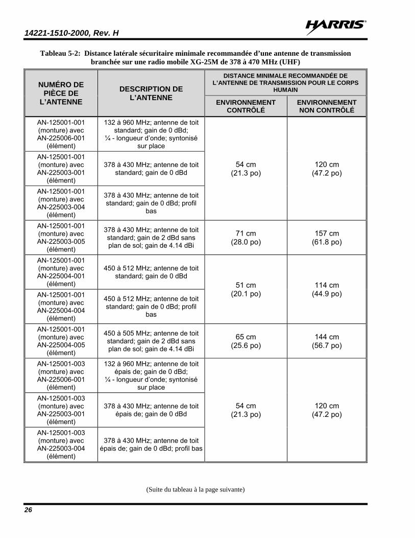
Branchée sur une Radio Mobile XG-25M de 136 à 174 MHz ............................................................ 25 Tableau 5-2: Distance latérale sécuritaire minimale recommandée d’une antenne de transmission branchée
sur une radio mobile XG-25M de 378 à 470 MHz (UHF) .................................................................. 26 Tableau 5-3 : Distance Latérale Sécuritaire Minimale Recommandée d’une Antenne de Transmission
Branchée sur une Radio Mobile XG-25M de 700/800 MHz ............................................................... 29 Table 6-1: Maritime Frequencies ................................................................................................................................ 33 Table 8-1: Button Functions ....................................................................................................................................... 42 Table 8-2: Status Icons ............................................................................................................................................... 43
14221-1510-2000, Rev. H
11
TABLE OF CONTENTS Page
Table 8-3: Menus for All Operating Modes (if programmed) .................................................................................... 56 Table 8-4: ECP Feature Numbers ............................................................................................................................... 60 Table 8-5: Messages Displayed during Trunked Operations ...................................................................................... 63 Table 8-6: Alert Tones during Trunked Operations ................................................................................................... 67 Table 8-7: Messages Displayed during P25 Conventional Operations ....................................................................... 82 Table 8-8: Alert Tones during P25 Conventional Operations .................................................................................... 85 Table 8-9: Messages Displayed during Analog Conventional Operations ................................................................. 90 Table 8-10: Alert Tones during Analog Conventional Operations ............................................................................. 92 Table 8-11: ProVoice Transmit/Receive Mode Compatibility ................................................................................. 101 Table 8-12: Display Number of Current Encryption Key ........................................................................................ 103 Table 9-1: Front Panel Default Controls and Functions ............................................................................................ 105 Table 9-2: Icons and Descriptions ............................................................................................................................. 108 Table 9-3: XG-25M OpenSky Mode Alert Tones ..................................................................................................... 111 Table 9-4: Basic Menu Structure ............................................................................................................................... 113 Table 9-5: Scan Modes .............................................................................................................................................. 123 Table 9-6: Status of Selective Call ............................................................................................................................ 124 Table 9-7: Status of Selective Alert ........................................................................................................................... 127
14221-1510-2000, Rev. H
12
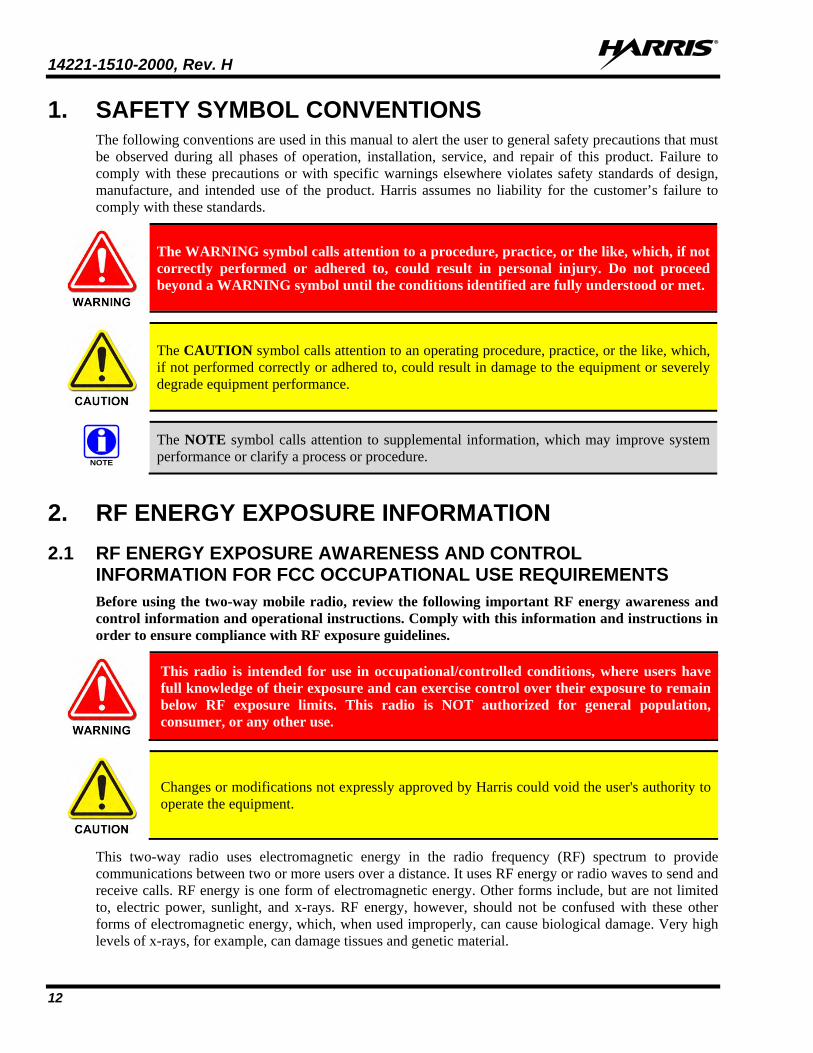
1. SAFETY SYMBOL CONVENTIONS The following conventions are used in this manual to alert the user to general safety precautions that must be observed during all phases of operation, installation, service, and repair of this product. Failure to comply with these precautions or with specific warnings elsewhere violates safety standards of design, manufacture, and intended use of the product. Harris assumes no liability for the customer’s failure to comply with these standards.
The WARNING symbol calls attention to a procedure, practice, or the like, which, if not correctly performed or adhered to, could result in personal injury. Do not proceed beyond a WARNING symbol until the conditions identified are fully understood or met.
The CAUTION symbol calls attention to an operating procedure, practice, or the like, which, if not performed correctly or adhered to, could result in damage to the equipment or severely degrade equipment performance.
NOTE
The NOTE symbol calls attention to supplemental information, which may improve system performance or clarify a process or procedure.
2. RF ENERGY EXPOSURE INFORMATION 2.1 RF ENERGY EXPOSURE AWARENESS AND CONTROL
INFORMATION FOR FCC OCCUPATIONAL USE REQUIREMENTS Before using the two-way mobile radio, review the following important RF energy awareness and control information and operational instructions. Comply with this information and instructions in order to ensure compliance with RF exposure guidelines.
This radio is intended for use in occupational/controlled conditions, where users have full knowledge of their exposure and can exercise control over their exposure to remain below RF exposure limits. This radio is NOT authorized for general population, consumer, or any other use.
Changes or modifications not expressly approved by Harris could void the user's authority to operate the equipment.
This two-way radio uses electromagnetic energy in the radio frequency (RF) spectrum to provide communications between two or more users over a distance. It uses RF energy or radio waves to send and receive calls. RF energy is one form of electromagnetic energy. Other forms include, but are not limited to, electric power, sunlight, and x-rays. RF energy, however, should not be confused with these other forms of electromagnetic energy, which, when used improperly, can cause biological damage. Very high levels of x-rays, for example, can damage tissues and genetic material.
14221-1510-2000, Rev. H
13
Experts in science, engineering, medicine, health, and industry work with organizations to develop standards for exposure to RF energy. These standards provide recommended levels of RF exposure for both workers and the general public. These recommended RF exposure levels include substantial margins of protection. All two-way radios marketed in North America are designed, manufactured, and tested to ensure they meet government-established RF exposure levels. In addition, manufacturers also recommend specific operating instructions to users of two-way radios. These instructions are important because they inform users about RF energy exposure and provide simple procedures on how to control it. Refer to the following websites for more information on what RF energy exposure is and how to control exposure to assure compliance with established RF exposure limits: http://www.fcc.gov/oet/rfsafety/rf-faqs.html http://www.osha.gov./SLTC/radiofrequencyradiation/index.html
2.1.1 Federal Communications Commission Regulations Before it was marketed in the United States, the XG-25M two-way mobile radio was tested to ensure compliance with FCC RF energy exposure limits for two-way mobile radios. When two-way radios are used as a consequence of employment, the FCC requires users to be fully aware of and able to control their exposure to meet occupational requirements. Exposure awareness can be facilitated by the use of a label directing users to specific user awareness information. The radio has an RF exposure product label. Also, the Product Safety Manual and this Operator’s Manual include information and operating instructions required to control RF exposure and to satisfy compliance requirements.
2.2 COMPLIANCE WITH RF EXPOSURE STANDARDS The XG-25M two-way mobile radio is designed and tested to comply with a number of national and international standards and guidelines regarding human exposure to RF electromagnetic energy. This radio complies with the IEEE and ICNIRP exposure limits for occupational/controlled RF exposure environment at duty-cycle times of up to 50% (50% transmit, 50% receive), and it is authorized by the FCC for occupational use. In terms of measuring RF energy for compliance with the FCC exposure guidelines, the radio’s antenna radiates measurable RF energy only while it is transmitting (talking), not when it is receiving (listening), or in a standby mode.
The XG-25M two-way mobile radio complies with the following RF energy exposure standards and guidelines: • United States Federal Communications Commission (FCC), Code of Federal Regulations; 47 CFR
§ 2 sub-part J. • American National Standards Institute (ANSI)/Institute of Electrical and Electronic Engineers (IEEE)
C95.1-2005. • Institute of Electrical and Electronic Engineers (IEEE) C95.1-2005. • IC Standard RSS-102, Issue 4, 2010: Spectrum Management and Telecommunications Radio
Standards Specification. Radiofrequency Exposure Compliance of Radio communication Apparatus (All Frequency Bands).
• DIRECTIVE 2004/40/EC OF THE EUROPEAN PARLIAMENT AND OF THE COUNCIL of 29 April 2004 on the minimum health and safety requirements regarding the exposure of workers to the risks arising from physical agents (electromagnetic fields) and amended by: Directive 2007/30/EC of the European Parliament and of the Council of 20 June 2007 Directive 2008/46/EC of the European Parliament and of the Council of 23 April 2008 Regulation (EC) No 1137/2008 of the European Parliament and of the Council of 22 October
2008 Directive 2012/11/EU of the European Parliament and of the Council of 19 April 2012
14221-1510-2000, Rev. H
14
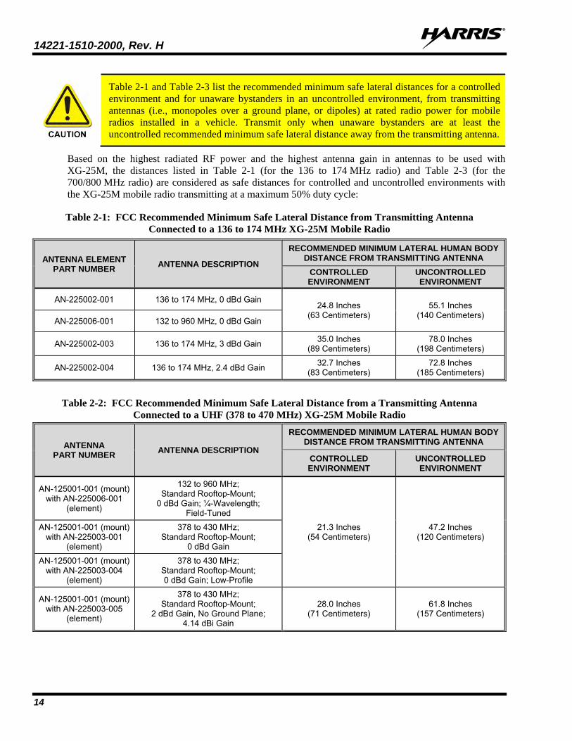
Table 2-1 and Table 2-3 list the recommended minimum safe lateral distances for a controlled environment and for unaware bystanders in an uncontrolled environment, from transmitting antennas (i.e., monopoles over a ground plane, or dipoles) at rated radio power for mobile radios installed in a vehicle. Transmit only when unaware bystanders are at least the uncontrolled recommended minimum safe lateral distance away from the transmitting antenna.
Based on the highest radiated RF power and the highest antenna gain in antennas to be used with XG-25M, the distances listed in Table 2-1 (for the 136 to 174 MHz radio) and Table 2-3 (for the 700/800 MHz radio) are considered as safe distances for controlled and uncontrolled environments with the XG-25M mobile radio transmitting at a maximum 50% duty cycle:
Table 2-1: FCC Recommended Minimum Safe Lateral Distance from Transmitting Antenna Connected to a 136 to 174 MHz XG-25M Mobile Radio
ANTENNA ELEMENT PART NUMBER ANTENNA DESCRIPTION
RECOMMENDED MINIMUM LATERAL HUMAN BODY DISTANCE FROM TRANSMITTING ANTENNA
CONTROLLED ENVIRONMENT
UNCONTROLLED ENVIRONMENT
AN-225002-001 136 to 174 MHz, 0 dBd Gain 24.8 Inches
(63 Centimeters) 55.1 Inches
(140 Centimeters) AN-225006-001 132 to 960 MHz, 0 dBd Gain
AN-225002-003 136 to 174 MHz, 3 dBd Gain 35.0 Inches (89 Centimeters)
78.0 Inches (198 Centimeters)
AN-225002-004 136 to 174 MHz, 2.4 dBd Gain 32.7 Inches (83 Centimeters)
72.8 Inches (185 Centimeters)
Table 2-2: FCC Recommended Minimum Safe Lateral Distance from a Transmitting Antenna
Connected to a UHF (378 to 470 MHz) XG-25M Mobile Radio
ANTENNA PART NUMBER ANTENNA DESCRIPTION
RECOMMENDED MINIMUM LATERAL HUMAN BODY DISTANCE FROM TRANSMITTING ANTENNA
CONTROLLED ENVIRONMENT
UNCONTROLLED ENVIRONMENT
AN-125001-001 (mount) with AN-225006-001
(element)
132 to 960 MHz; Standard Rooftop-Mount;
0 dBd Gain; ¼-Wavelength; Field-Tuned
21.3 Inches (54 Centimeters)
47.2 Inches (120 Centimeters)
AN-125001-001 (mount) with AN-225003-001
(element)
378 to 430 MHz; Standard Rooftop-Mount;
0 dBd Gain
AN-125001-001 (mount) with AN-225003-004
(element)
378 to 430 MHz; Standard Rooftop-Mount; 0 dBd Gain; Low-Profile
AN-125001-001 (mount) with AN-225003-005
(element)
378 to 430 MHz; Standard Rooftop-Mount;
2 dBd Gain, No Ground Plane; 4.14 dBi Gain
28.0 Inches (71 Centimeters)
61.8 Inches (157 Centimeters)
14221-1510-2000, Rev. H
15
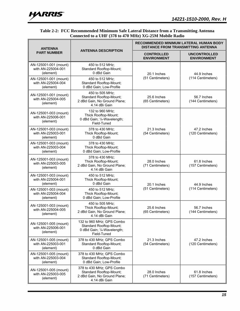
Table 2-2: FCC Recommended Minimum Safe Lateral Distance from a Transmitting Antenna Connected to a UHF (378 to 470 MHz) XG-25M Mobile Radio
ANTENNA PART NUMBER ANTENNA DESCRIPTION
RECOMMENDED MINIMUM LATERAL HUMAN BODY DISTANCE FROM TRANSMITTING ANTENNA
CONTROLLED ENVIRONMENT
UNCONTROLLED ENVIRONMENT
AN-125001-001 (mount) with AN-225004-001
(element)
450 to 512 MHz; Standard Rooftop-Mount;
0 dBd Gain 20.1 Inches (51 Centimeters)
44.9 Inches (114 Centimeters) AN-125001-001 (mount)
with AN-225004-004 (element)
450 to 512 MHz; Standard Rooftop-Mount; 0 dBd Gain; Low-Profile
AN-125001-001 (mount) with AN-225004-005
(element)
450 to 505 MHz; Standard Rooftop-Mount;
2 dBd Gain, No Ground Plane; 4.14 dBi Gain
25.6 Inches (65 Centimeters)
56.7 Inches (144 Centimeters)
AN-125001-003 (mount) with AN-225006-001
(element)
132 to 960 MHz; Thick Rooftop-Mount;
0 dBd Gain; ¼-Wavelength; Field-Tuned
21.3 Inches (54 Centimeters)
47.2 Inches (120 Centimeters)
AN-125001-003 (mount) with AN-225003-001
(element)
378 to 430 MHz; Thick Rooftop-Mount;
0 dBd Gain
AN-125001-003 (mount) with AN-225003-004
(element)
378 to 430 MHz; Thick Rooftop-Mount;
0 dBd Gain; Low-Profile
AN-125001-003 (mount) with AN-225003-005
(element)
378 to 430 MHz; Thick Rooftop-Mount;
2 dBd Gain, No Ground Plane; 4.14 dBi Gain
28.0 Inches (71 Centimeters)
61.8 Inches (157 Centimeters)
AN-125001-003 (mount) with AN-225004-001
(element)
450 to 512 MHz; Thick Rooftop-Mount;
0 dBd Gain 20.1 Inches (51 Centimeters)
44.9 Inches (114 Centimeters) AN-125001-003 (mount)
with AN-225004-004 (element)
450 to 512 MHz; Thick Rooftop-Mount;
0 dBd Gain; Low-Profile
AN-125001-003 (mount) with AN-225004-005
(element)
450 to 505 MHz; Thick Rooftop-Mount;
2 dBd Gain, No Ground Plane; 4.14 dBi Gain
25.6 Inches (65 Centimeters)
56.7 Inches (144 Centimeters)
AN-125001-005 (mount) with AN-225006-001
(element)
132 to 960 MHz; GPS Combo Standard Rooftop-Mount;
0 dBd Gain; ¼-Wavelength; Field-Tuned
21.3 Inches (54 Centimeters)
47.2 Inches (120 Centimeters)
AN-125001-005 (mount) with AN-225003-001
(element)
378 to 430 MHz; GPS Combo Standard Rooftop-Mount;
0 dBd Gain
AN-125001-005 (mount) with AN-225003-004
(element)
378 to 430 MHz; GPS Combo Standard Rooftop-Mount; 0 dBd Gain; Low-Profile
AN-125001-005 (mount) with AN-225003-005
(element)
378 to 430 MHz; GPS Combo Standard Rooftop-Mount;
2 dBd Gain, No Ground Plane; 4.14 dBi Gain
28.0 Inches (71 Centimeters)
61.8 Inches (157 Centimeters)
14221-1510-2000, Rev. H
16
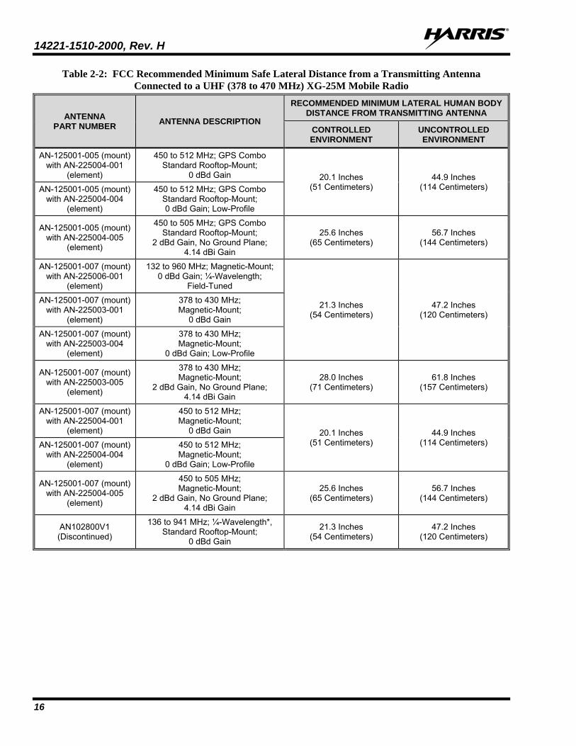
Table 2-2: FCC Recommended Minimum Safe Lateral Distance from a Transmitting Antenna Connected to a UHF (378 to 470 MHz) XG-25M Mobile Radio
ANTENNA PART NUMBER ANTENNA DESCRIPTION
RECOMMENDED MINIMUM LATERAL HUMAN BODY DISTANCE FROM TRANSMITTING ANTENNA
CONTROLLED ENVIRONMENT
UNCONTROLLED ENVIRONMENT
AN-125001-005 (mount) with AN-225004-001
(element)
450 to 512 MHz; GPS Combo Standard Rooftop-Mount;
0 dBd Gain 20.1 Inches (51 Centimeters)
44.9 Inches (114 Centimeters) AN-125001-005 (mount)
with AN-225004-004 (element)
450 to 512 MHz; GPS Combo Standard Rooftop-Mount; 0 dBd Gain; Low-Profile
AN-125001-005 (mount) with AN-225004-005
(element)
450 to 505 MHz; GPS Combo Standard Rooftop-Mount;
2 dBd Gain, No Ground Plane; 4.14 dBi Gain
25.6 Inches (65 Centimeters)
56.7 Inches (144 Centimeters)
AN-125001-007 (mount) with AN-225006-001
(element)
132 to 960 MHz; Magnetic-Mount; 0 dBd Gain; ¼-Wavelength;
Field-Tuned
21.3 Inches (54 Centimeters)
47.2 Inches (120 Centimeters)
AN-125001-007 (mount) with AN-225003-001
(element)
378 to 430 MHz; Magnetic-Mount;
0 dBd Gain
AN-125001-007 (mount) with AN-225003-004
(element)
378 to 430 MHz; Magnetic-Mount;
0 dBd Gain; Low-Profile
AN-125001-007 (mount) with AN-225003-005
(element)
378 to 430 MHz; Magnetic-Mount;
2 dBd Gain, No Ground Plane; 4.14 dBi Gain
28.0 Inches (71 Centimeters)
61.8 Inches (157 Centimeters)
AN-125001-007 (mount) with AN-225004-001
(element)
450 to 512 MHz; Magnetic-Mount;
0 dBd Gain 20.1 Inches (51 Centimeters)
44.9 Inches (114 Centimeters) AN-125001-007 (mount)
with AN-225004-004 (element)
450 to 512 MHz; Magnetic-Mount;
0 dBd Gain; Low-Profile
AN-125001-007 (mount) with AN-225004-005
(element)
450 to 505 MHz; Magnetic-Mount;
2 dBd Gain, No Ground Plane; 4.14 dBi Gain
25.6 Inches (65 Centimeters)
56.7 Inches (144 Centimeters)
AN102800V1 (Discontinued)
136 to 941 MHz; ¼-Wavelength*, Standard Rooftop-Mount;
0 dBd Gain
21.3 Inches (54 Centimeters)
47.2 Inches (120 Centimeters)
14221-1510-2000, Rev. H
17
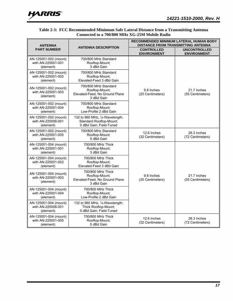
Table 2-3: FCC Recommended Minimum Safe Lateral Distance from a Transmitting Antenna Connected to a 700/800 MHz XG-25M Mobile Radio
ANTENNA PART NUMBER ANTENNA DESCRIPTION
RECOMMENDED MINIMUM LATERAL HUMAN BODY DISTANCE FROM TRANSMITTING ANTENNA
CONTROLLED ENVIRONMENT
UNCONTROLLED ENVIRONMENT
AN-125001-002 (mount) with AN-225001-001
(element)
700/800 MHz Standard Rooftop-Mount;
3 dBd Gain
9.8 Inches (25 Centimeters)
21.7 Inches (55 Centimeters)
AN-125001-002 (mount) with AN-225001-002
(element)
700/800 MHz Standard Rooftop-Mount;
Elevated-Feed 3 dBd Gain
AN-125001-002 (mount) with AN-225001-003
(element)
700/800 MHz Standard Rooftop-Mount;
Elevated-Feed, No Ground Plane 3 dBd Gain
AN-125001-002 (mount) with AN-225001-004
(element)
700/800 MHz Standard Rooftop-Mount;
Low-Profile 2 dBd Gain
AN-125001-002 (mount) with AN-225006-001
(element)
132 to 960 MHz, ¼-Wavelength; Standard Rooftop-Mount; 0 dBd Gain; Field-Tuned
AN-125001-002 (mount) with AN-225001-005
(element)
700/800 MHz Standard Rooftop-Mount;
5 dBd Gain
12.6 Inches (32 Centimeters)
28.3 Inches (72 Centimeters)
AN-125001-004 (mount) with AN-225001-001
(element)
700/800 MHz Thick Rooftop-Mount;
3 dBd Gain
9.8 Inches (25 Centimeters)
21.7 Inches (55 Centimeters)
AN-125001-004 (mount) with AN-225001-002
(element)
700/800 MHz Thick Rooftop-Mount;
Elevated-Feed 3 dBd Gain
AN-125001-004 (mount) with AN-225001-003
(element)
700/800 MHz Thick Rooftop-Mount;
Elevated-Feed, No Ground Plane 3 dBd Gain
AN-125001-004 (mount) with AN-225001-004
(element)
700/800 MHz Thick Rooftop-Mount;
Low-Profile 2 dBd Gain
AN-125001-004 (mount) with AN-225006-001
(element)
132 to 960 MHz, ¼-Wavelength; Thick Rooftop-Mount;
0 dBd Gain; Field-Tuned
AN-125001-004 (mount) with AN-225001-005
(element)
700/800 MHz Thick Rooftop-Mount;
5 dBd Gain
12.6 Inches (32 Centimeters)
28.3 Inches (72 Centimeters)
14221-1510-2000, Rev. H
18
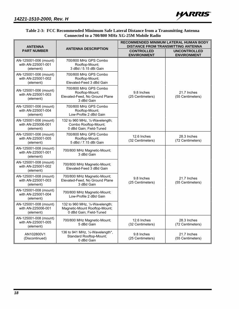
Table 2-3: FCC Recommended Minimum Safe Lateral Distance from a Transmitting Antenna Connected to a 700/800 MHz XG-25M Mobile Radio
ANTENNA PART NUMBER ANTENNA DESCRIPTION
RECOMMENDED MINIMUM LATERAL HUMAN BODY DISTANCE FROM TRANSMITTING ANTENNA
CONTROLLED ENVIRONMENT
UNCONTROLLED ENVIRONMENT
AN-125001-006 (mount) with AN-225001-001
(element)
700/800 MHz GPS Combo Rooftop-Mount;
3 dBd / 5.15 dBi Gain
9.8 Inches (25 Centimeters)
21.7 Inches (55 Centimeters)
AN-125001-006 (mount) with AN-225001-002
(element)
700/800 MHz GPS Combo Rooftop-Mount;
Elevated-Feed 3 dBd Gain
AN-125001-006 (mount) with AN-225001-003
(element)
700/800 MHz GPS Combo Rooftop-Mount;
Elevated-Feed, No Ground Plane 3 dBd Gain
AN-125001-006 (mount) with AN-225001-004
(element)
700/800 MHz GPS Combo Rooftop-Mount;
Low-Profile 2 dBd Gain
AN-125001-006 (mount) with AN-225006-001
(element)
132 to 960 MHz, ¼-Wavelength; Combo Rooftop-Mount; 0 dBd Gain; Field-Tuned
AN-125001-006 (mount) with AN-225001-005
(element)
700/800 MHz GPS Combo Rooftop-Mount;
5 dBd / 7.15 dBi Gain
12.6 Inches (32 Centimeters)
28.3 Inches (72 Centimeters)
AN-125001-008 (mount) with AN-225001-001
(element)
700/800 MHz Magnetic-Mount; 3 dBd Gain
9.8 Inches (25 Centimeters)
21.7 Inches (55 Centimeters)
AN-125001-008 (mount) with AN-225001-002
(element)
700/800 MHz Magnetic-Mount; Elevated-Feed 3 dBd Gain
AN-125001-008 (mount) with AN-225001-003
(element)
700/800 MHz Magnetic-Mount; Elevated-Feed, No Ground Plane
3 dBd Gain
AN-125001-008 (mount) with AN-225001-004
(element)
700/800 MHz Magnetic-Mount; Low-Profile 2 dBd Gain
AN-125001-008 (mount) with AN-225006-001
(element)
132 to 960 MHz, ¼-Wavelength; Magnetic-Mount Rooftop-Mount;
0 dBd Gain; Field-Tuned
AN-125001-008 (mount) with AN-225001-005
(element)
700/800 MHz Magnetic-Mount; 5 dBd Gain
12.6 Inches (32 Centimeters)
28.3 Inches (72 Centimeters)
AN102800V1 (Discontinued)
136 to 941 MHz, ¼-Wavelength*, Standard Rooftop-Mount;
0 dBd Gain
9.8 Inches (25 Centimeters)
21.7 Inches (55 Centimeters)
14221-1510-2000, Rev. H
19
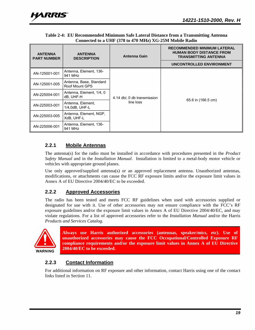
Table 2-4: EU Recommended Minimum Safe Lateral Distance from a Transmitting Antenna Connected to a UHF (378 to 470 MHz) XG-25M Mobile Radio
ANTENNA PART NUMBER
ANTENNA DESCRIPTION Antenna Gain
RECOMMENDED MINIMUM LATERAL HUMAN BODY DISTANCE FROM
TRANSMITTING ANTENNA
UNCONTROLLED ENVIRONMENT
AN-125001-001 Antenna, Element, 136-941 MHz
4.14 dbi; 0 db transmission line loss 65.6 in (166.5 cm)
AN-125001-005 Antenna, Base, Standard Roof Mount GPS
AN-225004-001 Antenna, Element, 1/4, 0 dB, UHF-H
AN-225003-001 Antenna, Element, 1/4,0dB, UHF-L
AN-225003-005 Antenna, Element, NGP, XdB, UHF-L
AN-225006-001 Antenna, Element, 136-941 MHz
2.2.1 Mobile Antennas The antenna(s) for the radio must be installed in accordance with procedures presented in the Product Safety Manual and in the Installation Manual. Installation is limited to a metal-body motor vehicle or vehicles with appropriate ground planes. Use only approved/supplied antenna(s) or an approved replacement antenna. Unauthorized antennas, modifications, or attachments can cause the FCC RF exposure limits and/or the exposure limit values in Annex A of EU Directive 2004/40/EC to be exceeded.
2.2.2 Approved Accessories The radio has been tested and meets FCC RF guidelines when used with accessories supplied or designated for use with it. Use of other accessories may not ensure compliance with the FCC’s RF exposure guidelines and/or the exposure limit values in Annex A of EU Directive 2004/40/EC, and may violate regulations. For a list of approved accessories refer to the Installation Manual and/or the Harris Products and Services Catalog.
Always use Harris authorized accessories (antennas, speaker/mics, etc). Use of unauthorized accessories may cause the FCC Occupational/Controlled Exposure RF compliance requirements and/or the exposure limit values in Annex A of EU Directive 2004/40/EC to be exceeded.
2.2.3 Contact Information For additional information on RF exposure and other information, contact Harris using one of the contact links listed in Section 11.
14221-1510-2000, Rev. H
20
3. OPERATION SAFETY RECOMMENDATIONS 3.1 OCCUPATIONAL SAFETY GUIDELINES AND SAFETY TRAINING
INFORMATION To ensure bodily exposure to RF electromagnetic energy is within the FCC allowable limits for occupational use and/or the exposure limit values in Annex A of EU Directive 2004/40/EC. Always adhere to the following basic guidelines:
• The push-to-talk button should only be depressed when intending to send a voice message.
• The radio should only be used for necessary work-related communications.
• The radio should only be used by authorized and trained personnel. It should never be operated by children.
• Do not attempt any unauthorized modification to the radio. Changes or modifications to the radio may cause harmful interference and/or cause it to exceed FCC RF exposure limits. Only qualified personnel should service the radio.
• Always use only authorized accessories (antennas, control heads, speakers/mics, etc.). Use of unauthorized accessories can cause the FCC RF exposure compliance requirements and/or the exposure limit values in Annex A of EU Directive 2004/40/EC to be exceeded.
The information listed above provides the user with information needed to make him or her aware of a RF exposure, and what to do to assure that this radio operates within the FCC exposure limits and/or the exposure limit values in Annex A of EU Directive 2004/40/EC.
3.2 TRANSMITTER HAZARDS
The operator of any mobile radio should be aware of certain hazards common to the operation of vehicular radio transmissions. Possible hazards include but are not limited to:
• Explosive Atmospheres — Just as it is dangerous to fuel a vehicle while its engine is running, be sure to turn the radio OFF while fueling the vehicle. If the radio is mounted in the trunk of the vehicle, DO NOT carry containers of fuel in the trunk.
Areas with potentially explosive atmosphere are often, but not always, clearly marked. Turn the radio OFF when in any area with a potentially explosive atmosphere. It is rare, but not impossible that the radio or its accessories could generate sparks.
• Interference To Vehicular Electronic Systems — Electronic fuel injection systems, electronic anti-skid braking systems, electronic cruise control systems, etc., are typical of the types of electronic devices that can malfunction due to the lack of protection from radio frequency (RF) energy present when transmitting. If the vehicle contains such equipment, consult the dealer for the make of vehicle and enlist their aid in determining if such electronic circuits perform normally when the radio is transmitting.
• Electric Blasting Caps — To prevent accidental detonation of electric blasting caps, DO NOT use two-way radios within 1000 feet (305 meters) of blasting operations. Always obey the “Turn Off Two-Way Radios” (or equivalent) signs posted where electric blasting caps are being used. (OSHA Standard: 1926.900).
14221-1510-2000, Rev. H
21
• Radio Frequency Energy — To prevent burns or related physical injury from radio frequency energy, do not operate the transmitter when anyone outside of the vehicle is within the minimum safe distance from the antenna as specified in Table 2-1. Refer to Section 2.1 for additional information.
• Vehicles Powered By Liquefied Petroleum (LP) Gas — Radio installation in vehicles powered by liquefied petroleum gas, where the LP gas container is located in the trunk or other sealed-off space within the interior of the vehicle, must conform to the National Fire Protection Association standard NFPA 58. This requires:
The space containing the radio equipment must be isolated by a seal from the space containing the LP gas container and its fittings.
Outside filling connections must be used for the LP gas container.
The LP gas container space shall be vented to the outside of the vehicle.
• Vehicles Equipped with Airbags — For driver and passenger safety, avoid mounting the radio’s control head (or any other component) above or near airbag deployment areas. In addition to driver-side and passenger-side front-impact airbags, some vehicles may also be equipped with side-impact airbags. For occupant safety, verify the location of all airbags within the vehicle before installing the radio equipment.
3.3 SAFE DRIVING RECOMMENDATIONS The American Automobile Association (AAA) advocates the following key safe driving recommenda-tions: • Read the literature on the safe operation of the radio. • Keep both hands on the steering wheel and the microphone in its hanger whenever the vehicle is in
motion. • Place calls only when the vehicle is stopped. • When talking from a moving vehicle is unavoidable, drive in the slower lane. Keep conversations
brief. • If a conversation requires taking notes or complex thought, stop the vehicle in a safe place and
continue the call. • Whenever using a mobile radio, exercise caution.
3.4 OPERATING RULES AND REGULATIONS Two-way radio systems must be operated in accordance with the rules and regulations of the local, regional, or national government.
In the United States, the XG-25M mobile radio must be operated in accordance with the rules and regulations of the Federal Communications Commission (FCC). Operators of two-way radio equipment must be thoroughly familiar with the rules that apply to the particular type of radio operation. Following these rules helps eliminate confusion, assures the most efficient use of the existing radio channels, and results in a smoothly functioning radio network.
When using a two-way radio, remember these rules: • It is a violation of FCC rules to interrupt any distress or emergency message. The radio operates in
much the same way as a telephone “party line.” Therefore, always listen to make sure the channel is clear before transmitting. Emergency calls have priority over all other messages. If someone is sending an emergency message – such as reporting a fire or asking for help in an accident, do not transmit unless assistance can be offered.
14221-1510-2000, Rev. H
22
• The use of profane or obscene language is prohibited by Federal law. • It is against the law to send false call letters or false distress or emergency messages. The FCC
requires keeping conversations brief and confined to business. Use coded messages whenever possible to save time.
• Using the radio to send personal messages (except in an emergency) is a violation of FCC rules. Send only essential messages.
• It is against Federal law to repeat or otherwise make known anything overheard on the radio. Conversations between others sharing the channel must be regarded as confidential.
• The FCC requires self-identification at certain specific times by means of call letters. Refer to the rules that apply to the particular type of operation for the proper procedure.
• No changes or adjustments shall be made to the equipment except by an authorized or certified electronics technician.
Under U.S. law, operation of an unlicensed radio transmitter within the jurisdiction of the United States may be punishable by a fine of up to $10,000, imprisonment for up to two (2) years, or both.
3.5 OPERATING TIPS The following conditions tend to reduce the effective range of two-way radios and should be avoided whenever possible: • Operating the radio in areas of low terrain, or while under power lines or bridges. • Obstructions such as mountains and buildings.
In areas where transmission or reception is poor, communication improvement may sometimes be obtained by moving a few yards in another direction, or moving to a higher elevation.
3.6 RADIO FREQUENCY INTERFERENCE This device complies with Part 15 of the FCC Rules. Operation is subject to the following two conditions:
1. This device may not cause harmful interference; and,
2. This device must accept any interference received, including interference that may cause undesired operation.
NOTE
14221-1510-2000, Rev. H
23
4. CONVENTIONS SUR LES SYMBOLES DE SÉCURITÉ Les conventions suivantes sont utilisées dans le présent manuel pour avertir l’utilisateur des précautions générales de sécurité qui doivent être observées pendant toutes les phases d’opération, d’entretien et de réparation de ce produit. Le non-respect de ces précautions ou d’avertissements précisés ailleurs enfreint les normes de sécurité de la conception, de la fabrication et de l’utilisation prévue du produit. Harris n’assume aucune responsabilité pour le non-respect de ces normes par le client.
Le symbole MISE EN GARDE attire l’attention sur une procédure ou une pratique qui, si elle n’est pas correctement effectuée ou observée, pourrait entraîner une blessure personnelle. Ne pas poursuivre au-delà d’un symbole de MISE EN GARDE avant que les conditions identifiées soient complètement comprises ou satisfaites.
Le symbole AVERTISSEMENT attire l’attention sur une procédure ou une pratique opérationnelle qui, si elle n’est pas correctement effectuée ou observée, pourrait entraîner un bris d’équipement ou une importante baisse de rendement de l’équipement.
REMARQUE
Le symbole REMARQUE attire l’attention sur des renseignements supplémentaires qui peuvent améliorer le rendement du système ou clarifier un processus ou une procédure.
5. RENSEIGNEMENTS SUR UNE EXPOSITION À L’ÉNERGIE DES RF
5.1 RENSEIGNEMENTS SUR LE CONTRÔLE ET LA SENSIBILISATION À L’ÉNERGIE DES RF POUR LES EXIGENCES D’UNE UTILISATION PROFESSIONNELLE DE LA FCC Avant d’utiliser les radios mobiles bidirectionnelles, passez en revue les renseignements et les instructions opérationnelles importants suivants sur le contrôle et la sensibilisation à l’énergie des RF. Se conformer à ces renseignements et instructions pour assurer la conformité aux directives d’exposition aux RF.
Cette radio est destinée à être utilisée dans des conditions professionnelles/ contrôlées, où les utilisateurs ont une pleine connaissance de leur exposition et peuvent exercer un contrôle sur leur exposition pour rester sous les limites d’exposition aux RF. Cette radio N’est PAS autorisée pour la population générale, les consommateurs ou toute autre utilisation.
Des changements ou modifications non expressément approuvés par Harris pourraient annuler le droit d’utilisation de l’équipement pour l’utilisateur.
14221-1510-2000, Rev. H
24
Cette radio bidirectionnelle utilise une énergie électromagnétique dans le spectre des radiofréquences (RF) pour permettre une communication à distance entre deux utilisateurs ou plus. Elle utilise l’énergie des RF ou les ondes radio pour envoyer et recevoir des appels. L’énergie des RF est une forme d’énergie électromagnétique. D’autres formes comprennent, entre autres, l’énergie électrique, la lumière du soleil et les rayons X. Toutefois, l’énergie des RF ne doit pas être confondue avec ces autres formes d’énergie électromagnétique qui, lorsque mal utilisées, peuvent causer des dommages biologiques. Par exemple, des niveaux très élevés de rayons X peuvent endommager les tissus et le matériel génétique.
Des experts en science, en ingénierie, en médecine, en santé et de l’industrie travaillent avec des organismes pour établir des normes pour l’exposition à l’énergie des RF. Ces normes procurent des niveaux recommandés d’exposition aux RF autant aux travailleurs qu’au grand public. Ces niveaux d’exposition aux RF recommandés comprennent d’importantes marges de protection. Toutes les radios bidirectionnelles commercialisées en Amérique du Nord sont conçues, fabriquées et testées pour s’assurer qu’elles satisfont les niveaux d’exposition aux RF établis par le gouvernement. Les fabricants recommandent également des consignes d’utilisation particulières aux utilisateurs de radios bidirectionnelles. Ces instructions sont importantes, car elles informent les utilisateurs sur l’exposition à l’énergie des RF et donnent des procédures simples sur la manière de contrôler cette exposition. Consultez les sites Web suivants (en anglais) pour de plus amples renseignements sur ce qu’est l’exposition à l’énergie des RF et comment contrôler l’exposition pour assurer la conformité aux limites d’exposition établies : http://www.fcc.gov/oet/rfsafety/rf-faqs.html http://www.osha.gov./SLTC/radiofrequencyradiation/index.html
5.1.1 Règlements de la Federal Communications Commission (« Commission fédérale des communications » aux États-Unis)
Avant d’être mise sur le marché aux États-Unis, la radio mobile bidirectionnelle XG-25M a été testée pour s’assurer de sa conformité aux limites d’exposition à l’énergie des RF de la FCC pour les radios mobiles bidirectionnelles. Lorsque les radios bidirectionnelles sont utilisées à la suite d’une embauche, la FCC demande aux utilisateurs de bien connaître et de pouvoir contrôler leur exposition pour satisfaire les exigences professionnelles. La sensibilisation à l’exposition peut être facilitée par l’utilisation d’une étiquette qui dirige les utilisateurs vers des renseignements particuliers sur la sensibilisation de l’utilisateur. La radio possède une étiquette de produit sur l’exposition aux RF. De plus, le Manuel sur la sécurité du produit et le présent Manuel de l’opérateur comprennent des renseignements et les consignes d’utilisation nécessaires pour contrôler l’exposition aux RF et pour satisfaire les exigences de conformité.
5.2 CONFORMITÉ AUX NORMES D’EXPOSITION AUX RF La radio mobile bidirectionnelle XG-25M est conçue et testée pour être conforme à un certain nombre de normes et directives nationales et internationales quant à l’exposition humaine à l’énergie électromagnétique des RF. Cette radio est conforme aux limites d’exposition de l’IEEE et de la Commission internationale de protection contre les rayonnements non ionisants pour un environnement professionnel/contrôlé d’exposition aux RF à des périodes de cycle de service allant jusqu’à 50 % (50 % de transmission, 50 % de réception) et elle est autorisée par la FCC pour une utilisation professionnelle. Sur le plan de la mesure de l’énergie des RF pour la conformité aux directives d’exposition de la FCC, l’antenne de la radio irradie une énergie des RF mesurable seulement lorsqu’elle transmet (parler), et non lorsqu’elle reçoit (écouter) ou en mode d’attente.
La radio mobile bidirectionnelle XG-25M est conforme aux normes et directives d’exposition à l’énergie des RF suivantes : • Federal Communications Commission (FCC) américaine, le Code of Federal Regulations; 47 CFR
§ 2 sous-partie J.
14221-1510-2000, Rev. H
25
• American National Standards Institute (ANSI)/Institute of Electrical and Electronic Engineers (IEEE) C95.1-2005.
• Institute of Electrical and Electronic Engineers (IEEE) C95.1-2005. • IC Standard RSS-102, numéro 2, 2005 : Spectrum Management and Telecommunications Radio
Standards Specification. Radiofrequency Exposure Compliance of Radio communication Apparatus (All Frequency Bands).
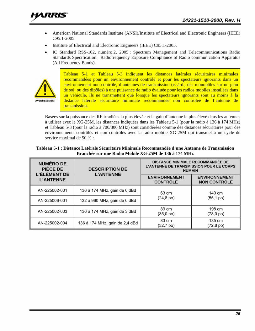
Tableau 5-1 et Tableau 5-3 indiquent les distances latérales sécuritaires minimales recommandées pour un environnement contrôlé et pour les spectateurs ignorants dans un environnement non contrôlé, d’antennes de transmission (c.-à-d., des monopôles sur un plan de sol, ou des dipôles) à une puissance de radio évaluée pour les radios mobiles installées dans un véhicule. Ils ne transmettent que lorsque les spectateurs ignorants sont au moins à la distance latérale sécuritaire minimale recommandée non contrôlée de l’antenne de transmission.
Basées sur la puissance des RF irradiées la plus élevée et le gain d’antenne le plus élevé dans les antennes à utiliser avec le XG-25M, les distances indiquées dans les Tableau 5-1 (pour la radio à 136 à 174 MHz) et Tableau 5-3 (pour la radio à 700/800 MHz) sont considérées comme des distances sécuritaires pour des environnements contrôlés et non contrôlés avec la radio mobile XG-25M qui transmet à un cycle de service maximal de 50 % :
Tableau 5-1 : Distance Latérale Sécuritaire Minimale Recommandée d’une Antenne de Transmission Branchée sur une Radio Mobile XG-25M de 136 à 174 MHz
NUMÉRO DE PIÈCE DE
L’ÉLÉMENT DE L’ANTENNE
DESCRIPTION DE L’ANTENNE
DISTANCE MINIMALE RECOMMANDÉE DE L’ANTENNE DE TRANSMISSION POUR LE CORPS
HUMAIN
ENVIRONNEMENT CONTRÔLÉ
ENVIRONNEMENT NON CONTRÔLÉ
AN-225002-001 136 à 174 MHz, gain de 0 dBd 63 cm (24,8 po)
140 cm (55,1 po) AN-225006-001 132 à 960 MHz, gain de 0 dBd
AN-225002-003 136 à 174 MHz, gain de 3 dBd 89 cm (35,0 po)
198 cm (78,0 po)
AN-225002-004 136 à 174 MHz, gain de 2,4 dBd 83 cm (32,7 po)
185 cm (72,8 po)
14221-1510-2000, Rev. H
26
Tableau 5-2: Distance latérale sécuritaire minimale recommandée d’une antenne de transmission branchée sur une radio mobile XG-25M de 378 à 470 MHz (UHF)
NUMÉRO DE PIÈCE DE
L’ANTENNE DESCRIPTION DE
L’ANTENNE
DISTANCE MINIMALE RECOMMANDÉE DE L’ANTENNE DE TRANSMISSION POUR LE CORPS
HUMAIN
ENVIRONNEMENT CONTRÔLÉ
ENVIRONNEMENT NON CONTRÔLÉ
AN-125001-001 (monture) avec AN-225006-001
(élément)
132 à 960 MHz; antenne de toit standard; gain de 0 dBd;
¼ - longueur d’onde; syntonisé sur place
54 cm (21.3 po)
120 cm (47.2 po)
AN-125001-001 (monture) avec AN-225003-001
(élément)
378 à 430 MHz; antenne de toit standard; gain de 0 dBd
AN-125001-001 (monture) avec AN-225003-004
(élément)
378 à 430 MHz; antenne de toit standard; gain de 0 dBd; profil
bas
AN-125001-001 (monture) avec AN-225003-005
(élément)
378 à 430 MHz; antenne de toit standard; gain de 2 dBd sans plan de sol; gain de 4.14 dBi
71 cm (28.0 po)
157 cm (61.8 po)
AN-125001-001 (monture) avec AN-225004-001
(élément)
450 à 512 MHz; antenne de toit standard; gain de 0 dBd
51 cm (20.1 po)
114 cm (44.9 po) AN-125001-001
(monture) avec AN-225004-004
(élément)
450 à 512 MHz; antenne de toit standard; gain de 0 dBd; profil
bas
AN-125001-001 (monture) avec AN-225004-005
(élément)
450 à 505 MHz; antenne de toit standard; gain de 2 dBd sans plan de sol; gain de 4.14 dBi
65 cm (25.6 po)
144 cm (56.7 po)
AN-125001-003 (monture) avec AN-225006-001
(élément)
132 à 960 MHz; antenne de toit épais de; gain de 0 dBd;
¼ - longueur d’onde; syntonisé sur place
54 cm (21.3 po)
120 cm (47.2 po)
AN-125001-003 (monture) avec AN-225003-001
(élément)
378 à 430 MHz; antenne de toit épais de; gain de 0 dBd
AN-125001-003 (monture) avec AN-225003-004
(élément)
378 à 430 MHz; antenne de toit épais de; gain de 0 dBd; profil bas
(Suite du tableau à la page suivante)
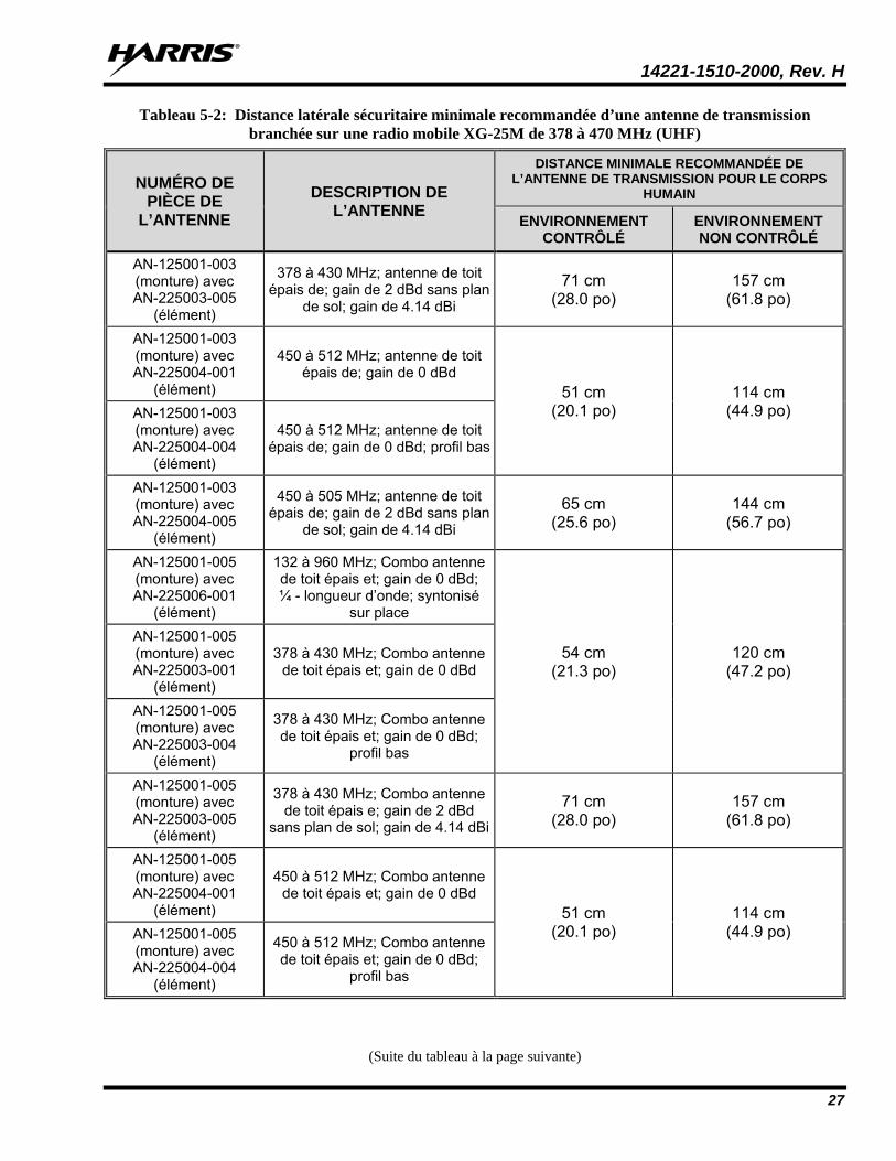
14221-1510-2000, Rev. H
27
Tableau 5-2: Distance latérale sécuritaire minimale recommandée d’une antenne de transmission branchée sur une radio mobile XG-25M de 378 à 470 MHz (UHF)
NUMÉRO DE PIÈCE DE
L’ANTENNE DESCRIPTION DE
L’ANTENNE
DISTANCE MINIMALE RECOMMANDÉE DE L’ANTENNE DE TRANSMISSION POUR LE CORPS
HUMAIN
ENVIRONNEMENT CONTRÔLÉ
ENVIRONNEMENT NON CONTRÔLÉ
AN-125001-003 (monture) avec AN-225003-005
(élément)
378 à 430 MHz; antenne de toit épais de; gain de 2 dBd sans plan
de sol; gain de 4.14 dBi
71 cm (28.0 po)
157 cm (61.8 po)
AN-125001-003 (monture) avec AN-225004-001
(élément)
450 à 512 MHz; antenne de toit épais de; gain de 0 dBd
51 cm (20.1 po)
114 cm (44.9 po) AN-125001-003
(monture) avec AN-225004-004
(élément)
450 à 512 MHz; antenne de toit épais de; gain de 0 dBd; profil bas
AN-125001-003 (monture) avec AN-225004-005
(élément)
450 à 505 MHz; antenne de toit épais de; gain de 2 dBd sans plan
de sol; gain de 4.14 dBi
65 cm (25.6 po)
144 cm (56.7 po)
AN-125001-005 (monture) avec AN-225006-001
(élément)
132 à 960 MHz; Combo antenne de toit épais et; gain de 0 dBd; ¼ - longueur d’onde; syntonisé
sur place
54 cm (21.3 po)
120 cm (47.2 po)
AN-125001-005 (monture) avec AN-225003-001
(élément)
378 à 430 MHz; Combo antenne de toit épais et; gain de 0 dBd
AN-125001-005 (monture) avec AN-225003-004
(élément)
378 à 430 MHz; Combo antenne de toit épais et; gain de 0 dBd;
profil bas
AN-125001-005 (monture) avec AN-225003-005
(élément)
378 à 430 MHz; Combo antenne de toit épais e; gain de 2 dBd
sans plan de sol; gain de 4.14 dBi
71 cm (28.0 po)
157 cm (61.8 po)
AN-125001-005 (monture) avec AN-225004-001
(élément)
450 à 512 MHz; Combo antenne de toit épais et; gain de 0 dBd
51 cm (20.1 po)
114 cm (44.9 po) AN-125001-005
(monture) avec AN-225004-004
(élément)
450 à 512 MHz; Combo antenne de toit épais et; gain de 0 dBd;
profil bas
(Suite du tableau à la page suivante)
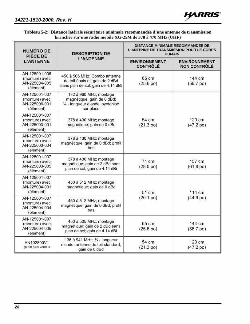
14221-1510-2000, Rev. H
28
Tableau 5-2: Distance latérale sécuritaire minimale recommandée d’une antenne de transmission branchée sur une radio mobile XG-25M de 378 à 470 MHz (UHF)
NUMÉRO DE PIÈCE DE
L’ANTENNE DESCRIPTION DE
L’ANTENNE
DISTANCE MINIMALE RECOMMANDÉE DE L’ANTENNE DE TRANSMISSION POUR LE CORPS
HUMAIN
ENVIRONNEMENT CONTRÔLÉ
ENVIRONNEMENT NON CONTRÔLÉ
AN-125001-005 (monture) avec AN-225004-005
(élément)
450 à 505 MHz; Combo antenne de toit épais et; gain de 2 dBd
sans plan de sol; gain de 4.14 dBi
65 cm (25.6 po)
144 cm (56.7 po)
AN-125001-007 (monture) avec AN-225006-001
(élément)
132 à 960 MHz; montage magnétique; gain de 0 dBd;
¼ - longueur d’onde; syntonisé sur place
54 cm (21.3 po)
120 cm (47.2 po)
AN-125001-007 (monture) avec AN-225003-001
(élément)
378 à 430 MHz; montage magnétique; gain de 0 dBd
AN-125001-007 (monture) avec AN-225003-004
(élément)
378 à 430 MHz; montage magnétique; gain de 0 dBd; profil
bas
AN-125001-007 (monture) avec AN-225003-005
(élément)
378 à 430 MHz; montage magnétique; gain de 2 dBd sans
plan de sol; gain de 4.14 dBi
71 cm (28.0 po)
157 cm (61.8 po)
AN-125001-007 (monture) avec AN-225004-001
(élément)
450 à 512 MHz; montage magnétique; gain de 0 dBd
51 cm (20.1 po)
114 cm (44.9 po) AN-125001-007
(monture) avec AN-225004-004
(élément)
450 à 512 MHz; montage magnétique; gain de 0 dBd; profil
bas
AN-125001-007 (monture) avec AN-225004-005
(élément)
450 à 505 MHz; montage magnétique; gain de 2 dBd sans
plan de sol; gain de 4.14 dBi
65 cm (25.6 po)
144 cm (56.7 po)
AN102800V1 (n’est plus vendu)
136 à 941 MHz; ¼ - longueur d’onde, antenne de toit standard;
gain de 0 dBd
54 cm (21.3 po)
120 cm (47.2 po)
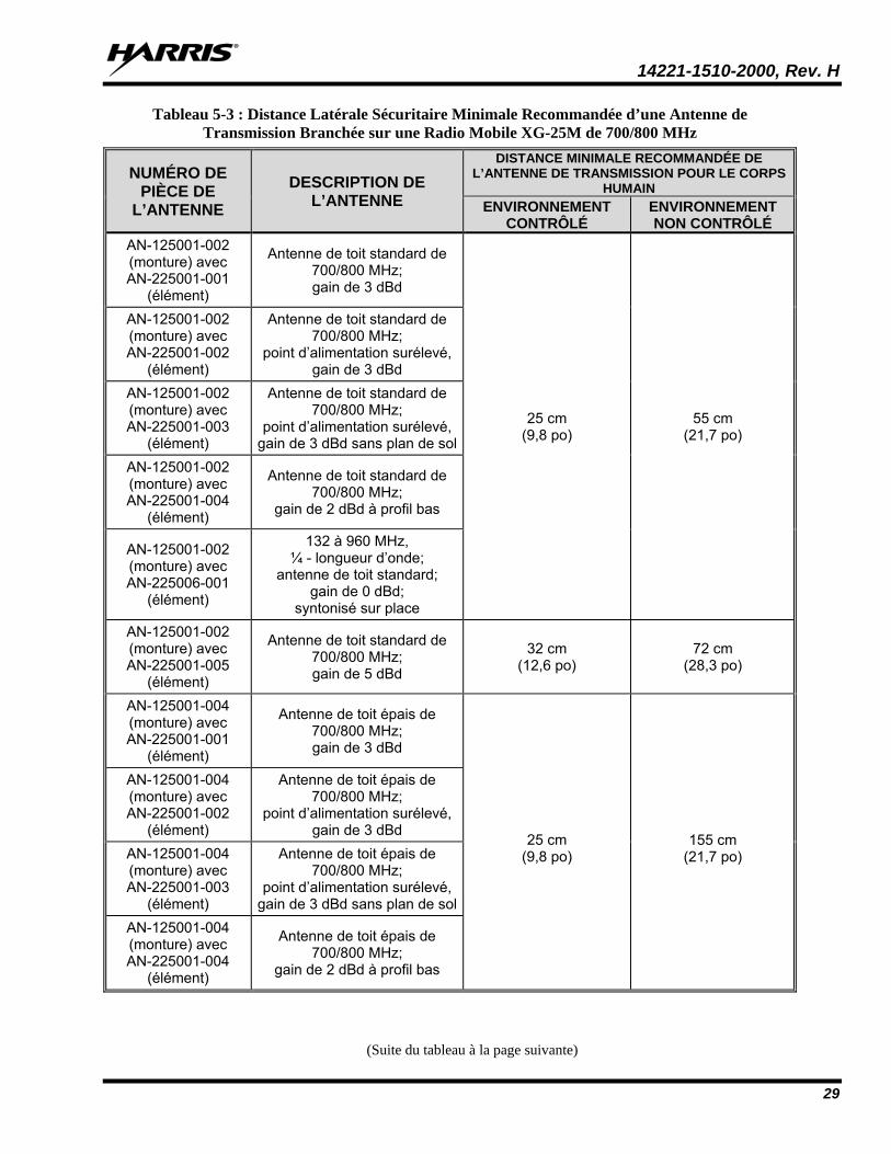
14221-1510-2000, Rev. H
29
Tableau 5-3 : Distance Latérale Sécuritaire Minimale Recommandée d’une Antenne de Transmission Branchée sur une Radio Mobile XG-25M de 700/800 MHz
NUMÉRO DE PIÈCE DE
L’ANTENNE
DESCRIPTION DE L’ANTENNE
DISTANCE MINIMALE RECOMMANDÉE DE L’ANTENNE DE TRANSMISSION POUR LE CORPS
HUMAIN ENVIRONNEMENT
CONTRÔLÉ ENVIRONNEMENT NON CONTRÔLÉ
AN-125001-002 (monture) avec AN-225001-001
(élément)
Antenne de toit standard de 700/800 MHz; gain de 3 dBd
25 cm (9,8 po)
55 cm (21,7 po)
AN-125001-002 (monture) avec AN-225001-002
(élément)
Antenne de toit standard de 700/800 MHz;
point d’alimentation surélevé, gain de 3 dBd
AN-125001-002 (monture) avec AN-225001-003
(élément)
Antenne de toit standard de 700/800 MHz;
point d’alimentation surélevé, gain de 3 dBd sans plan de sol
AN-125001-002 (monture) avec AN-225001-004
(élément)
Antenne de toit standard de 700/800 MHz;
gain de 2 dBd à profil bas
AN-125001-002 (monture) avec AN-225006-001
(élément)
132 à 960 MHz, ¼ - longueur d’onde;
antenne de toit standard; gain de 0 dBd;
syntonisé sur place AN-125001-002 (monture) avec AN-225001-005
(élément)
Antenne de toit standard de 700/800 MHz; gain de 5 dBd
32 cm (12,6 po)
72 cm (28,3 po)
AN-125001-004 (monture) avec AN-225001-001
(élément)
Antenne de toit épais de 700/800 MHz; gain de 3 dBd
25 cm (9,8 po)
155 cm (21,7 po)
AN-125001-004 (monture) avec AN-225001-002
(élément)
Antenne de toit épais de 700/800 MHz;
point d’alimentation surélevé, gain de 3 dBd
AN-125001-004 (monture) avec AN-225001-003
(élément)
Antenne de toit épais de 700/800 MHz;
point d’alimentation surélevé, gain de 3 dBd sans plan de sol
AN-125001-004 (monture) avec AN-225001-004
(élément)
Antenne de toit épais de 700/800 MHz;
gain de 2 dBd à profil bas
(Suite du tableau à la page suivante)
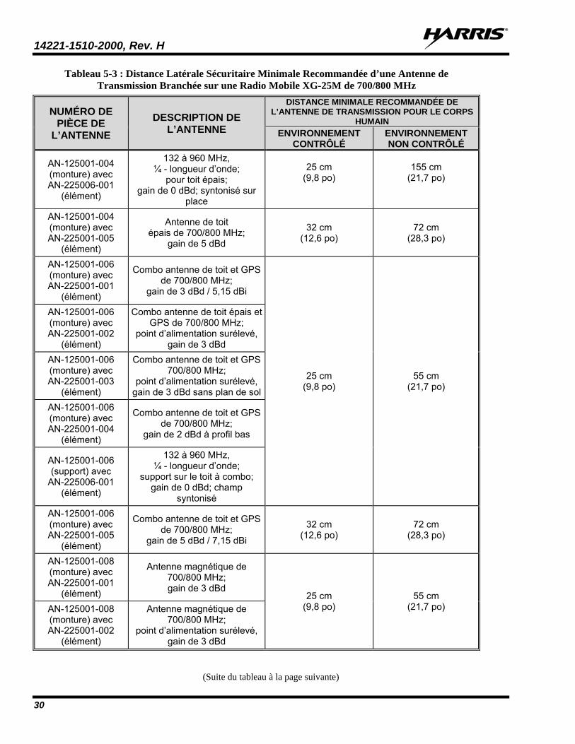
14221-1510-2000, Rev. H
30
Tableau 5-3 : Distance Latérale Sécuritaire Minimale Recommandée d’une Antenne de Transmission Branchée sur une Radio Mobile XG-25M de 700/800 MHz
NUMÉRO DE PIÈCE DE
L’ANTENNE
DESCRIPTION DE L’ANTENNE
DISTANCE MINIMALE RECOMMANDÉE DE L’ANTENNE DE TRANSMISSION POUR LE CORPS
HUMAIN ENVIRONNEMENT
CONTRÔLÉ ENVIRONNEMENT NON CONTRÔLÉ
AN-125001-004 (monture) avec AN-225006-001
(élément)
132 à 960 MHz, ¼ - longueur d’onde;
pour toit épais; gain de 0 dBd; syntonisé sur
place
25 cm
(9,8 po)
155 cm
(21,7 po)
AN-125001-004 (monture) avec AN-225001-005
(élément)
Antenne de toit épais de 700/800 MHz;
gain de 5 dBd
32 cm (12,6 po)
72 cm (28,3 po)
AN-125001-006 (monture) avec AN-225001-001
(élément)
Combo antenne de toit et GPS de 700/800 MHz;
gain de 3 dBd / 5,15 dBi
25 cm (9,8 po)
55 cm (21,7 po)
AN-125001-006 (monture) avec AN-225001-002
(élément)
Combo antenne de toit épais et GPS de 700/800 MHz;
point d’alimentation surélevé, gain de 3 dBd
AN-125001-006 (monture) avec AN-225001-003
(élément)
Combo antenne de toit et GPS 700/800 MHz;
point d’alimentation surélevé, gain de 3 dBd sans plan de sol
AN-125001-006 (monture) avec AN-225001-004
(élément)
Combo antenne de toit et GPS de 700/800 MHz;
gain de 2 dBd à profil bas
AN-125001-006 (support) avec
AN-225006-001 (élément)
132 à 960 MHz, ¼ - longueur d’onde;
support sur le toit à combo; gain de 0 dBd; champ
syntonisé AN-125001-006 (monture) avec AN-225001-005
(élément)
Combo antenne de toit et GPS de 700/800 MHz;
gain de 5 dBd / 7,15 dBi
32 cm (12,6 po)
72 cm (28,3 po)
AN-125001-008 (monture) avec AN-225001-001
(élément)
Antenne magnétique de 700/800 MHz; gain de 3 dBd
25 cm (9,8 po)
55 cm (21,7 po) AN-125001-008
(monture) avec AN-225001-002
(élément)
Antenne magnétique de 700/800 MHz;
point d’alimentation surélevé, gain de 3 dBd
(Suite du tableau à la page suivante)
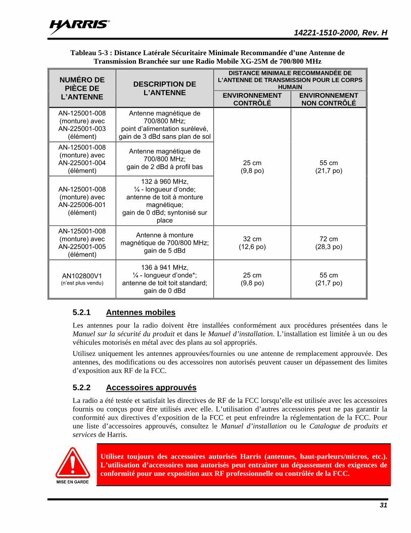
14221-1510-2000, Rev. H
31
Tableau 5-3 : Distance Latérale Sécuritaire Minimale Recommandée d’une Antenne de Transmission Branchée sur une Radio Mobile XG-25M de 700/800 MHz
NUMÉRO DE PIÈCE DE
L’ANTENNE
DESCRIPTION DE L’ANTENNE
DISTANCE MINIMALE RECOMMANDÉE DE L’ANTENNE DE TRANSMISSION POUR LE CORPS
HUMAIN ENVIRONNEMENT
CONTRÔLÉ ENVIRONNEMENT NON CONTRÔLÉ
AN-125001-008 (monture) avec AN-225001-003
(élément)
Antenne magnétique de 700/800 MHz;
point d’alimentation surélevé, gain de 3 dBd sans plan de sol
25 cm (9,8 po)
55 cm (21,7 po)
AN-125001-008 (monture) avec AN-225001-004
(élément)
Antenne magnétique de 700/800 MHz;
gain de 2 dBd à profil bas
AN-125001-008 (monture) avec AN-225006-001
(élément)
132 à 960 MHz, ¼ - longueur d’onde;
antenne de toit à monture magnétique;
gain de 0 dBd; syntonisé sur place
AN-125001-008 (monture) avec AN-225001-005
(élément)
Antenne à monture magnétique de 700/800 MHz;
gain de 5 dBd
32 cm (12,6 po)
72 cm (28,3 po)
AN102800V1 (n’est plus vendu)
136 à 941 MHz, ¼ - longueur d’onde*;
antenne de toit toit standard; gain de 0 dBd
25 cm (9,8 po)
55 cm (21,7 po)
5.2.1 Antennes mobiles Les antennes pour la radio doivent être installées conformément aux procédures présentées dans le Manuel sur la sécurité du produit et dans le Manuel d’installation. L’installation est limitée à un ou des véhicules motorisés en métal avec des plans au sol appropriés. Utilisez uniquement les antennes approuvées/fournies ou une antenne de remplacement approuvée. Des antennes, des modifications ou des accessoires non autorisés peuvent causer un dépassement des limites d’exposition aux RF de la FCC.
5.2.2 Accessoires approuvés La radio a été testée et satisfait les directives de RF de la FCC lorsqu’elle est utilisée avec les accessoires fournis ou conçus pour être utilisés avec elle. L’utilisation d’autres accessoires peut ne pas garantir la conformité aux directives d’exposition de la FCC et peut enfreindre la réglementation de la FCC. Pour une liste d’accessoires approuvés, consultez le Manuel d’installation ou le Catalogue de produits et services de Harris.
Utilisez toujours des accessoires autorisés Harris (antennes, haut-parleurs/micros, etc.). L’utilisation d’accessoires non autorisés peut entraîner un dépassement des exigences de conformité pour une exposition aux RF professionnelle ou contrôlée de la FCC.
14221-1510-2000, Rev. H
32
5.2.3 Coordonnées Pour de plus amples renseignements sur l’exposition aux RF ou d’autres renseignements, contactez Harris en utilisant l’un des liens apparaissant à la Section 11.
5.3 INTERFÉRENCE DES RADIOFRÉQUENCES
5.3.1 Partie 15 de la FCC Cet appareil est conforme à la Partie 15 de la réglementation de la FCC. Le fonctionnement est soumis aux deux conditions suivantes :
1. Cet appareil ne doit pas causer une interférence nuisible; et
2. Cet appareil doit accepter toute interférence reçue, y compris une interférence qui peut causer un fonctionnement non souhaité.
5.3.2 Industrie Canada Cet appareil est conforme aux normes RSS exemptées de licence d’Industrie Canada. Le fonctionnement est soumis aux deux conditions suivantes : (1) cet appareil ne doit pas causer d’interférence et (2) cet appareil doit accepter toute interférence, y compris une interférence qui peut causer un fonctionnement non souhaité de l’appareil.
5.4 RENSEIGNEMENTS SUR LA FORMATION SUR LA SANTÉ ET LA SÉCURITÉ AU TRAVAIL S’assurer que l’exposition physique à l’énergie électromagnétique des RF se situe dans les limites acceptables de la FCC pour l’utilisation professionnelle. Toujours se conformer aux directives de base suivantes :
• Le bouton de microphone doit être abaissé seulement lorsque l’on souhaite envoyer un message vocal.
• La radio doit être utilisée seulement pour les communications nécessaires liées au travail.
• La radio doit être utilisée seulement par du personnel autorisé et formé. Elle ne doit jamais être utilisée par des enfants.
• Ne tentez pas d’apporter une modification non autorisée à la radio. Des changements ou des modifications à la radio peuvent causer une interférence nocive ou entraîner un dépassement des limites d’exposition aux RF de la FCC. Seul le personnel qualifié doit utiliser la radio.
• Utilisez toujours seulement des accessoires autorisés (antennes, haut-parleurs/micros, etc.). L’utilisation d’accessoires non autorisés peut entraîner un dépassement des exigences de conformité pour une exposition aux RF de la FCC.
Les renseignements donnés ci-dessus donnent à l’utilisateur les renseignements nécessaires pour le sensibiliser à l’exposition aux RF et sur ce qu’il faut faire pour s’assurer que cette radio fonctionne dans les limites d’exposition de la FCC de cette radio.
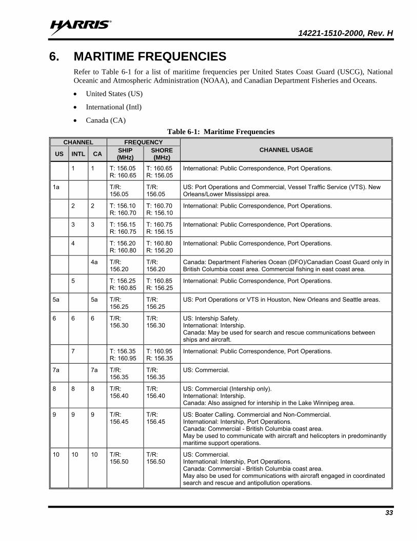
14221-1510-2000, Rev. H
33
6. MARITIME FREQUENCIES Refer to Table 6-1 for a list of maritime frequencies per United States Coast Guard (USCG), National Oceanic and Atmospheric Administration (NOAA), and Canadian Department Fisheries and Oceans.
• United States (US)
• International (Intl)
• Canada (CA) Table 6-1: Maritime Frequencies
CHANNEL FREQUENCY CHANNEL USAGE US INTL CA SHIP
(MHz) SHORE (MHz)
1 1 T: 156.05 R: 160.65
T: 160.65 R: 156.05
International: Public Correspondence, Port Operations.
1a T/R: 156.05
T/R: 156.05
US: Port Operations and Commercial, Vessel Traffic Service (VTS). New Orleans/Lower Mississippi area.
2 2 T: 156.10 R: 160.70
T: 160.70 R: 156.10
International: Public Correspondence, Port Operations.
3 3 T: 156.15 R: 160.75
T: 160.75 R: 156.15
International: Public Correspondence, Port Operations.
4 T: 156.20 R: 160.80
T: 160.80 R: 156.20
International: Public Correspondence, Port Operations.
4a T/R: 156.20
T/R: 156.20
Canada: Department Fisheries Ocean (DFO)/Canadian Coast Guard only in British Columbia coast area. Commercial fishing in east coast area.
5 T: 156.25 R: 160.85
T: 160.85 R: 156.25
International: Public Correspondence, Port Operations.
5a 5a T/R: 156.25
T/R: 156.25
US: Port Operations or VTS in Houston, New Orleans and Seattle areas.
6 6 6 T/R: 156.30
T/R: 156.30
US: Intership Safety. International: Intership. Canada: May be used for search and rescue communications between ships and aircraft.
7 T: 156.35 R: 160.95
T: 160.95 R: 156.35
International: Public Correspondence, Port Operations.
7a 7a T/R: 156.35
T/R: 156.35
US: Commercial.
8 8 8 T/R: 156.40
T/R: 156.40
US: Commercial (Intership only). International: Intership. Canada: Also assigned for intership in the Lake Winnipeg area.
9 9 9 T/R: 156.45
T/R: 156.45
US: Boater Calling. Commercial and Non-Commercial. International: Intership, Port Operations. Canada: Commercial - British Columbia coast area. May be used to communicate with aircraft and helicopters in predominantly maritime support operations.
10 10 10 T/R: 156.50
T/R: 156.50
US: Commercial. International: Intership, Port Operations. Canada: Commercial - British Columbia coast area. May also be used for communications with aircraft engaged in coordinated search and rescue and antipollution operations.
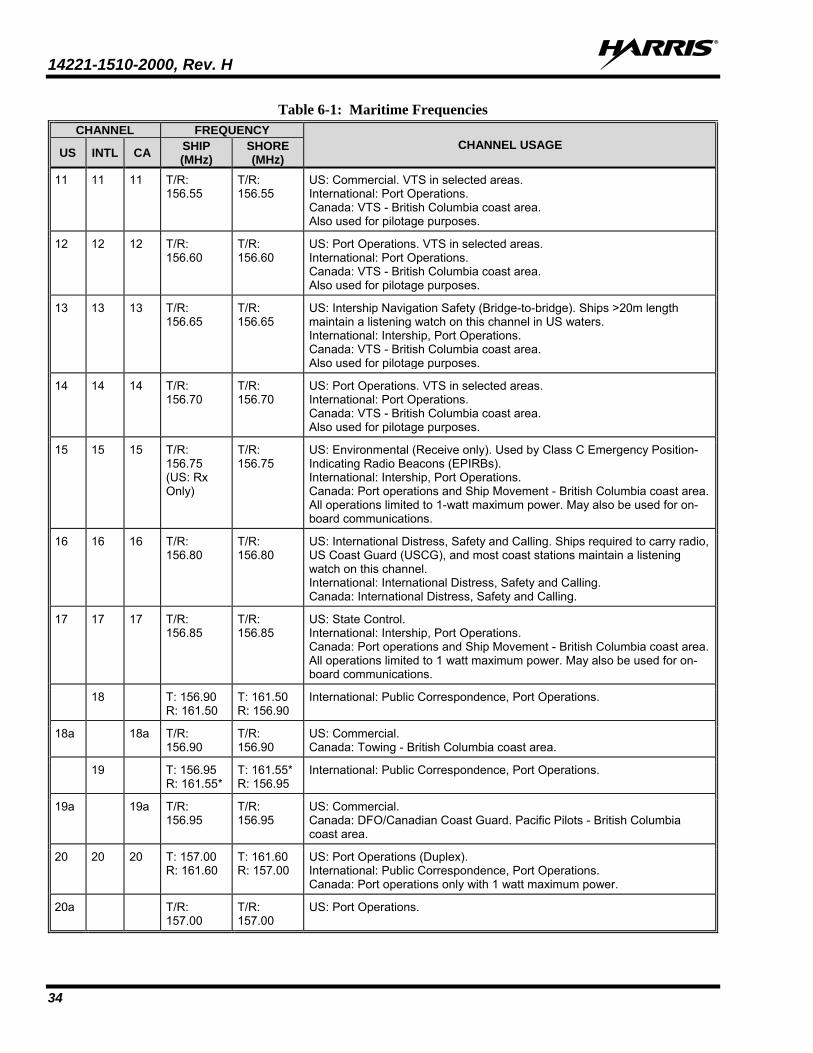
14221-1510-2000, Rev. H
34
Table 6-1: Maritime Frequencies CHANNEL FREQUENCY
CHANNEL USAGE US INTL CA SHIP (MHz)
SHORE (MHz)
11 11 11 T/R: 156.55
T/R: 156.55
US: Commercial. VTS in selected areas. International: Port Operations. Canada: VTS - British Columbia coast area. Also used for pilotage purposes.
12 12 12 T/R: 156.60
T/R: 156.60
US: Port Operations. VTS in selected areas. International: Port Operations. Canada: VTS - British Columbia coast area. Also used for pilotage purposes.
13 13 13 T/R: 156.65
T/R: 156.65
US: Intership Navigation Safety (Bridge-to-bridge). Ships >20m length maintain a listening watch on this channel in US waters. International: Intership, Port Operations. Canada: VTS - British Columbia coast area. Also used for pilotage purposes.
14 14 14 T/R: 156.70
T/R: 156.70
US: Port Operations. VTS in selected areas. International: Port Operations. Canada: VTS - British Columbia coast area. Also used for pilotage purposes.
15 15 15 T/R: 156.75 (US: Rx Only)
T/R: 156.75
US: Environmental (Receive only). Used by Class C Emergency Position-Indicating Radio Beacons (EPIRBs). International: Intership, Port Operations. Canada: Port operations and Ship Movement - British Columbia coast area. All operations limited to 1-watt maximum power. May also be used for on-board communications.
16 16 16 T/R: 156.80
T/R: 156.80
US: International Distress, Safety and Calling. Ships required to carry radio, US Coast Guard (USCG), and most coast stations maintain a listening watch on this channel. International: International Distress, Safety and Calling. Canada: International Distress, Safety and Calling.
17 17 17 T/R: 156.85
T/R: 156.85
US: State Control. International: Intership, Port Operations. Canada: Port operations and Ship Movement - British Columbia coast area. All operations limited to 1 watt maximum power. May also be used for on-board communications.
18 T: 156.90 R: 161.50
T: 161.50 R: 156.90
International: Public Correspondence, Port Operations.
18a 18a T/R: 156.90
T/R: 156.90
US: Commercial. Canada: Towing - British Columbia coast area.
19 T: 156.95 R: 161.55*
T: 161.55* R: 156.95
International: Public Correspondence, Port Operations.
19a 19a T/R: 156.95
T/R: 156.95
US: Commercial. Canada: DFO/Canadian Coast Guard. Pacific Pilots - British Columbia coast area.
20 20 20 T: 157.00 R: 161.60
T: 161.60 R: 157.00
US: Port Operations (Duplex). International: Public Correspondence, Port Operations. Canada: Port operations only with 1 watt maximum power.
20a T/R: 157.00
T/R: 157.00
US: Port Operations.
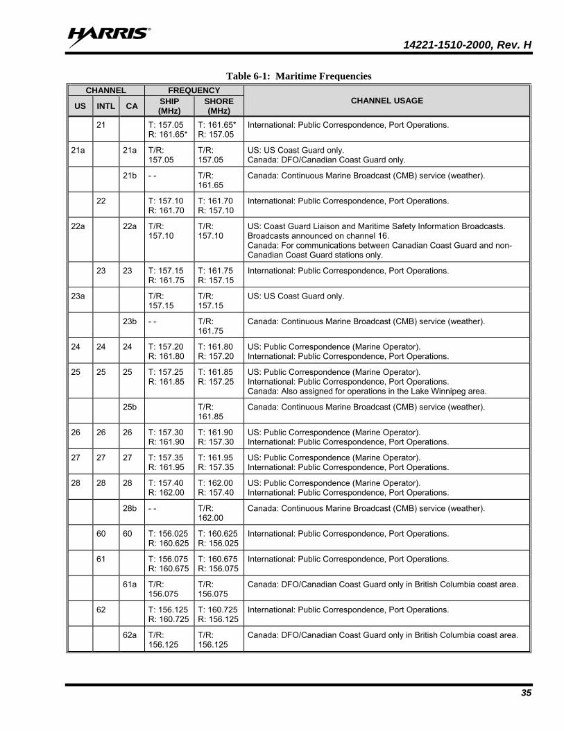
14221-1510-2000, Rev. H
35
Table 6-1: Maritime Frequencies CHANNEL FREQUENCY
CHANNEL USAGE US INTL CA SHIP (MHz)
SHORE (MHz)
21 T: 157.05 R: 161.65*
T: 161.65* R: 157.05
International: Public Correspondence, Port Operations.
21a 21a T/R: 157.05
T/R: 157.05
US: US Coast Guard only. Canada: DFO/Canadian Coast Guard only.
21b - - T/R: 161.65
Canada: Continuous Marine Broadcast (CMB) service (weather).
22 T: 157.10 R: 161.70
T: 161.70 R: 157.10
International: Public Correspondence, Port Operations.
22a 22a T/R: 157.10
T/R: 157.10
US: Coast Guard Liaison and Maritime Safety Information Broadcasts. Broadcasts announced on channel 16. Canada: For communications between Canadian Coast Guard and non-Canadian Coast Guard stations only.
23 23 T: 157.15 R: 161.75
T: 161.75 R: 157.15
International: Public Correspondence, Port Operations.
23a T/R: 157.15
T/R: 157.15
US: US Coast Guard only.
23b - - T/R: 161.75
Canada: Continuous Marine Broadcast (CMB) service (weather).
24 24 24 T: 157.20 R: 161.80
T: 161.80 R: 157.20
US: Public Correspondence (Marine Operator). International: Public Correspondence, Port Operations.
25 25 25 T: 157.25 R: 161.85
T: 161.85 R: 157.25
US: Public Correspondence (Marine Operator). International: Public Correspondence, Port Operations. Canada: Also assigned for operations in the Lake Winnipeg area.
25b T/R: 161.85
Canada: Continuous Marine Broadcast (CMB) service (weather).
26 26 26 T: 157.30 R: 161.90
T: 161.90 R: 157.30
US: Public Correspondence (Marine Operator). International: Public Correspondence, Port Operations.
27 27 27 T: 157.35 R: 161.95
T: 161.95 R: 157.35
US: Public Correspondence (Marine Operator). International: Public Correspondence, Port Operations.
28 28 28 T: 157.40 R: 162.00
T: 162.00 R: 157.40
US: Public Correspondence (Marine Operator). International: Public Correspondence, Port Operations.
28b - - T/R: 162.00
Canada: Continuous Marine Broadcast (CMB) service (weather).
60 60 T: 156.025 R: 160.625
T: 160.625 R: 156.025
International: Public Correspondence, Port Operations.
61 T: 156.075 R: 160.675
T: 160.675 R: 156.075
International: Public Correspondence, Port Operations.
61a T/R: 156.075
T/R: 156.075
Canada: DFO/Canadian Coast Guard only in British Columbia coast area.
62 T: 156.125 R: 160.725
T: 160.725 R: 156.125
International: Public Correspondence, Port Operations.
62a T/R: 156.125
T/R: 156.125
Canada: DFO/Canadian Coast Guard only in British Columbia coast area.
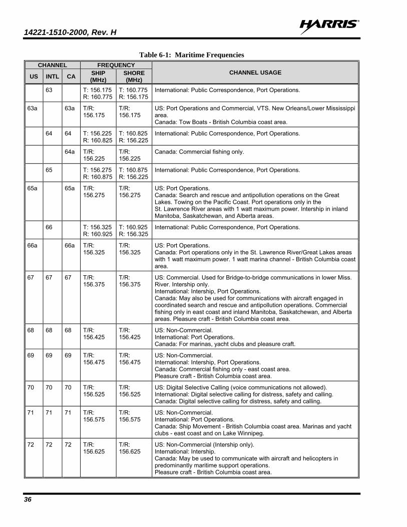
14221-1510-2000, Rev. H
36
Table 6-1: Maritime Frequencies CHANNEL FREQUENCY
CHANNEL USAGE US INTL CA SHIP (MHz)
SHORE (MHz)
63 T: 156.175 R: 160.775
T: 160.775 R: 156.175
International: Public Correspondence, Port Operations.
63a 63a T/R: 156.175
T/R: 156.175
US: Port Operations and Commercial, VTS. New Orleans/Lower Mississippi area. Canada: Tow Boats - British Columbia coast area.
64 64 T: 156.225 R: 160.825
T: 160.825 R: 156.225
International: Public Correspondence, Port Operations.
64a T/R: 156.225
T/R: 156.225
Canada: Commercial fishing only.
65 T: 156.275 R: 160.875
T: 160.875 R: 156.225
International: Public Correspondence, Port Operations.
65a 65a T/R: 156.275
T/R: 156.275
US: Port Operations. Canada: Search and rescue and antipollution operations on the Great Lakes. Towing on the Pacific Coast. Port operations only in the St. Lawrence River areas with 1 watt maximum power. Intership in inland Manitoba, Saskatchewan, and Alberta areas.
66 T: 156.325 R: 160.925
T: 160.925 R: 156.325
International: Public Correspondence, Port Operations.
66a 66a T/R: 156.325
T/R: 156.325
US: Port Operations. Canada: Port operations only in the St. Lawrence River/Great Lakes areas with 1 watt maximum power. 1 watt marina channel - British Columbia coast area.
67 67 67 T/R: 156.375
T/R: 156.375
US: Commercial. Used for Bridge-to-bridge communications in lower Miss. River. Intership only. International: Intership, Port Operations. Canada: May also be used for communications with aircraft engaged in coordinated search and rescue and antipollution operations. Commercial fishing only in east coast and inland Manitoba, Saskatchewan, and Alberta areas. Pleasure craft - British Columbia coast area.
68 68 68 T/R: 156.425
T/R: 156.425
US: Non-Commercial. International: Port Operations. Canada: For marinas, yacht clubs and pleasure craft.
69 69 69 T/R: 156.475
T/R: 156.475
US: Non-Commercial. International: Intership, Port Operations. Canada: Commercial fishing only - east coast area. Pleasure craft - British Columbia coast area.
70 70 70 T/R: 156.525
T/R: 156.525
US: Digital Selective Calling (voice communications not allowed). International: Digital selective calling for distress, safety and calling. Canada: Digital selective calling for distress, safety and calling.
71 71 71 T/R: 156.575
T/R: 156.575
US: Non-Commercial. International: Port Operations. Canada: Ship Movement - British Columbia coast area. Marinas and yacht clubs - east coast and on Lake Winnipeg.
72 72 72 T/R: 156.625
T/R: 156.625
US: Non-Commercial (Intership only). International: Intership. Canada: May be used to communicate with aircraft and helicopters in predominantly maritime support operations. Pleasure craft - British Columbia coast area.
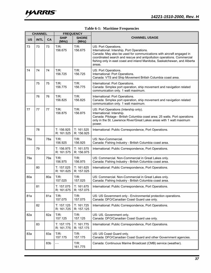
14221-1510-2000, Rev. H
37
Table 6-1: Maritime Frequencies CHANNEL FREQUENCY
CHANNEL USAGE US INTL CA SHIP (MHz)
SHORE (MHz)
73 73 73 T/R: 156.675
T/R: 156.675
US: Port Operations. International: Intership, Port Operations. Canada: May also be used for communications with aircraft engaged in coordinated search and rescue and antipollution operations. Commercial fishing only in east coast and inland Manitoba, Saskatchewan, and Alberta areas.
74 74 74 T/R: 156.725
T/R: 156.725
US: Port Operations. International: Port Operations. Canada: VTS and Ship Movement British Columbia coast area.
75 75 T/R: 156.775
T/R: 156.775
International: Port Operations. Canada: Simplex port operation, ship movement and navigation related communication only. 1 watt maximum.
76 76 T/R: 156.825
T/R: 156.825
International: Port Operations. Canada: Simplex port operation, ship movement and navigation related communication only. 1 watt maximum.
77 77 77 T/R: 156.875
T/R: 156.875
US: Port Operations (Intership only). International: Intership. Canada: Pilotage - British Columbia coast area; 25 watts. Port operations only in the St. Lawrence River/Great Lakes areas with 1 watt maximum power.
78 T: 156.925 R: 161.525
T: 161.525 R: 156.925
International: Public Correspondence, Port Operations.
78a 78a T/R: 156.925
T/R: 156.925
US: Non-Commercial. Canada: Fishing Industry - British Columbia coast area.
79 T: 156.975 R: 161.575
T: 161.575 R: 156.975
International: Public Correspondence, Port Operations.
79a 79a T/R: 156.975
T/R: 156.975
US: Commercial. Non-Commercial in Great Lakes only. Canada: Fishing Industry - British Columbia coast area.
80 T: 157.025 R: 161.625
T: 161.625 R: 157.025
International: Public Correspondence, Port Operations.
80a 80a T/R: 157.025
T/R: 157.025
US: Commercial. Non-Commercial in Great Lakes only. Canada: Fishing Industry - British Columbia coast area.
81 T: 157.075 R: 161.675
T: 161.675 R: 157.075
International: Public Correspondence, Port Operations.
81a 81a T/R: 157.075
T/R: 157.075
US: US Government only - Environmental protection operations. Canada: DFO/Canadian Coast Guard use only.
82 T: 157.125 R: 161.725
T: 161.725 R: 157.125
International: Public Correspondence, Port Operations.
82a 82a T/R: 157.125
T/R: 157.125
US: US. Government only. Canada: DFO/Canadian Coast Guard use only.
83 T: 157.175 R: 161.775
T: 161.775 R: 157.175
International: Public Correspondence, Port Operations.
83a 83a T/R: 157.175
T/R: 157.175
US: US Coast Guard only. Canada: DFO/Canadian Coast Guard and other Government agencies.
83b - - T/R: 161.775
Canada: Continuous Marine Broadcast (CMB) service (weather).
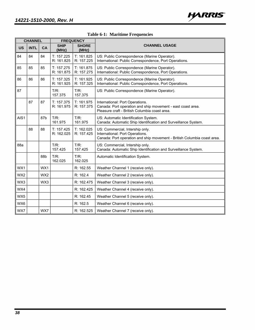
14221-1510-2000, Rev. H
38
Table 6-1: Maritime Frequencies CHANNEL FREQUENCY
CHANNEL USAGE US INTL CA SHIP (MHz)
SHORE (MHz)
84 84 84 T: 157.225 R: 161.825
T: 161.825 R: 157.225
US: Public Correspondence (Marine Operator). International: Public Correspondence, Port Operations.
85 85 85 T: 157.275 R: 161.875
T: 161.875 R: 157.275
US: Public Correspondence (Marine Operator). International: Public Correspondence, Port Operations.
86 86 86 T: 157.325 R: 161.925
T: 161.925 R: 157.325
US: Public Correspondence (Marine Operator). International: Public Correspondence, Port Operations.
87 T/R: 157.375
T/R: 157.375
US: Public Correspondence (Marine Operator).
87 87 T: 157.375 R: 161.975
T: 161.975 R: 157.375
International: Port Operations. Canada: Port operation and ship movement - east coast area. Pleasure craft - British Columbia coast area.
AIS1 87b T/R: 161.975
T/R: 161.975
US: Automatic Identification System. Canada: Automatic Ship Identification and Surveillance System.
88 88 T: 157.425 R: 162.025
T: 162.025 R: 157.425
US: Commercial, Intership only. International: Port Operations. Canada: Port operation and ship movement - British Columbia coast area.
88a T/R: 157.425
T/R: 157.425
US: Commercial, Intership only. Canada: Automatic Ship Identification and Surveillance System.
88b T/R: 162.025
T/R: 162.025
Automatic Identification System.
WX1 WX1 R: 162.55 Weather Channel 1 (receive only).
WX2 WX2 R: 162.4 Weather Channel 2 (receive only).
WX3 WX3 R: 162.475 Weather Channel 3 (receive only).
WX4 R: 162.425 Weather Channel 4 (receive only).
WX5 R: 162.45 Weather Channel 5 (receive only).
WX6 R: 162.5 Weather Channel 6 (receive only).
WX7 WX7 R: 162.525 Weather Channel 7 (receive only).
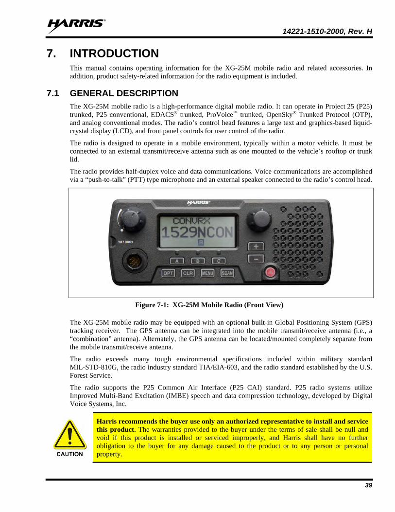
14221-1510-2000, Rev. H
39
7. INTRODUCTION This manual contains operating information for the XG-25M mobile radio and related accessories. In addition, product safety-related information for the radio equipment is included.
7.1 GENERAL DESCRIPTION The XG-25M mobile radio is a high-performance digital mobile radio. It can operate in Project 25 (P25) trunked, P25 conventional, EDACS® trunked, ProVoice™ trunked, OpenSky® Trunked Protocol (OTP), and analog conventional modes. The radio’s control head features a large text and graphics-based liquid-crystal display (LCD), and front panel controls for user control of the radio.
The radio is designed to operate in a mobile environment, typically within a motor vehicle. It must be connected to an external transmit/receive antenna such as one mounted to the vehicle’s rooftop or trunk lid.
The radio provides half-duplex voice and data communications. Voice communications are accomplished via a “push-to-talk” (PTT) type microphone and an external speaker connected to the radio’s control head.
Figure 7-1: XG-25M Mobile Radio (Front View)
The XG-25M mobile radio may be equipped with an optional built-in Global Positioning System (GPS) tracking receiver. The GPS antenna can be integrated into the mobile transmit/receive antenna (i.e., a “combination” antenna). Alternately, the GPS antenna can be located/mounted completely separate from the mobile transmit/receive antenna.
The radio exceeds many tough environmental specifications included within military standard MIL-STD-810G, the radio industry standard TIA/EIA-603, and the radio standard established by the U.S. Forest Service.
The radio supports the P25 Common Air Interface (P25 CAI) standard. P25 radio systems utilize Improved Multi-Band Excitation (IMBE) speech and data compression technology, developed by Digital Voice Systems, Inc.
Harris recommends the buyer use only an authorized representative to install and service this product. The warranties provided to the buyer under the terms of sale shall be null and void if this product is installed or serviced improperly, and Harris shall have no further obligation to the buyer for any damage caused to the product or to any person or personal property.
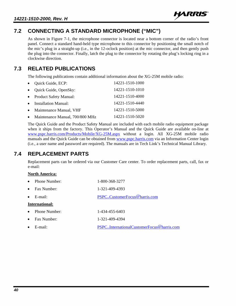
14221-1510-2000, Rev. H
40
7.2 CONNECTING A STANDARD MICROPHONE (“MIC”) As shown in Figure 7-1, the microphone connector is located near a bottom corner of the radio’s front panel. Connect a standard hand-held type microphone to this connector by positioning the small notch of the mic’s plug in a straight-up (i.e., in the 12-oclock position) at the mic connector, and then gently push the plug into the connector. Finally, latch the plug to the connector by rotating the plug’s locking ring in a clockwise direction.
7.3 RELATED PUBLICATIONS The following publications contain additional information about the XG-25M mobile radio: • Quick Guide, ECP: 14221-1510-1000
• Quick Guide, OpenSky: 14221-1510-1010
• Product Safety Manual: 14221-1510-4000
• Installation Manual: 14221-1510-4440
• Maintenance Manual, VHF 14221-1510-5000
• Maintenance Manual, 700/800 MHz 14221-1510-5020
The Quick Guide and the Product Safety Manual are included with each mobile radio equipment package when it ships from the factory. This Operator’s Manual and the Quick Guide are available on-line at www.pspc.harris.com/Products/Mobile/XG-25M.aspx without a login. All XG-25M mobile radio manuals and the Quick Guide can be obtained from www.pspc.harris.com via an Information Center login (i.e., a user name and password are required). The manuals are in Tech Link’s Technical Manual Library.
7.4 REPLACEMENT PARTS Replacement parts can be ordered via our Customer Care center. To order replacement parts, call, fax or e-mail:
North America:
• Phone Number: 1-800-368-3277
• Fax Number: 1-321-409-4393
• E-mail: [email protected]
International:
• Phone Number: 1-434-455-6403
• Fax Number: 1-321-409-4394
• E-mail: [email protected]
14221-1510-2000, Rev. H
41
8. EDACS, CONVENTIONAL, AND P25 OPERATION 8.1 CH-25 FRONT PANEL COMPONENTS
The radio’s control head features a large text and graphics-based liquid-crystal display (LCD), controls for menu navigation, an emergency button, three pre-set buttons, a Power On-Off/Volume Control knob, and a microphone connector.
Figure 8-1: CH-25 Front Panel Components
8.2 POWER ON/OFF/VOLUME CONTROL The radio’s Power On/Off/Volume control is located on the top-left corner of its front panel. See Figure 8-1. To turn on the radio, rotate this control clockwise out of the detent position. To turn the radio off, rotate this control fully counter-clockwise until it returns to the detent position, as sensed by a click of the control. See Section 8.9.1 for additional information.
8.3 VOICE ANNUNCIATION When enabled via programming, the Voice Annunciation feature provides audible feedback for various radio operations. The radio can be programmed to play an audio message for any or all of the following. This message can be a pre-recorded (canned) message or a user-recorded message.
• Channel changes
• System changes
• Encryption On/Off
• Noise Cancellation On/Off
• Scan On/Off
• Talkaround On/Off
For more information on configuring the radio for Voice Annunciation, refer to the Voice Annunciation Feature manual 14221-7200-6110.
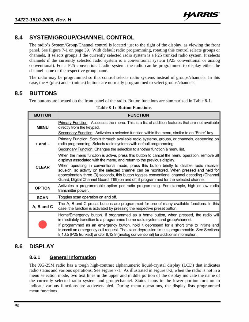
14221-1510-2000, Rev. H
42
8.4 SYSTEM/GROUP/CHANNEL CONTROL The radio’s System/Group/Channel control is located just to the right of the display, as viewing the front panel. See Figure 7-1 on page 39. With default radio programming, rotating this control selects groups or channels. It selects groups if the currently selected radio system is a P25 trunked radio system. It selects channels if the currently selected radio system is a conventional system (P25 conventional or analog conventional). For a P25 conventional radio system, the radio can be programmed to display either the channel name or the respective group name. The radio may be programmed so this control selects radio systems instead of groups/channels. In this case, the + (plus) and – (minus) buttons are normally programmed to select groups/channels.
8.5 BUTTONS Ten buttons are located on the front panel of the radio. Button functions are summarized in Table 8-1.
Table 8-1: Button Functions
BUTTON FUNCTION
MENU Primary Function: Accesses the menu. This is a list of addition features that are not available directly from the keypad. Secondary Function: Activates a selected function within the menu, similar to an “Enter” key.
+ and – Primary Function: Scrolls through available radio systems, groups, or channels, depending on radio programming. Selects radio systems with default programming. Secondary Function: Changes the selection to another function a menu list.
CLEAR
When the menu function is active, press this button to cancel the menu operation, remove all displays associated with the menu, and return to the previous display. When operating in conventional mode, press this button briefly to disable radio receiver squelch, so activity on the selected channel can be monitored. When pressed and held for approximately three (3) seconds, this button toggles conventional channel decoding (Channel Guard, Digital Channel Guard, T99) on and off, if programmed for the selected channel.
OPTION Activates a programmable option per radio programming. For example, high or low radio transmitter power.
SCAN Toggles scan operation on and off.
A, B and C The A, B and C preset buttons are programmed for one of many available functions. In this case, the function is activated by pressing the respective preset button.
Home/Emergency button. If programmed as a home button, when pressed, the radio will immediately transition to a programmed home radio system and group/channel. If programmed as an emergency button, hold it depressed for a short time to initiate and transmit an emergency call request. The exact depression time is programmable. See Sections 8.10.5 (P25 trunked) and/or 8.12.9 (analog conventional) for additional information.
8.6 DISPLAY
8.6.1 General Information The XG-25M radio has a tough high-contrast alphanumeric liquid-crystal display (LCD) that indicates radio status and various operations. See Figure 7-1. As illustrated in Figure 8-2, when the radio is not in a menu selection mode, two text lines in the upper and middle portion of the display indicate the name of the currently selected radio system and group/channel. Status icons in the lower portion turn on to indicate various functions are active/enabled. During menu operations, the display lists programmed menu functions.
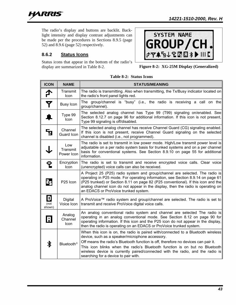
14221-1510-2000, Rev. H
43
The radio’s display and buttons are backlit. Back-light intensity and display contrast adjustments can be made per the procedures in Sections 8.9.5 (page 52) and 8.9.6 (page 52) respectively.
8.6.2 Status Icons Status icons that appear in the bottom of the radio’s display are summarized in Table 8-2.
Table 8-2: Status Icons
ICON NAME STATUS/MEANING
Transmit
Icon The radio is transmitting. Also when transmitting, the Tx/Busy indicator located on the radio’s front panel lights red.
Busy Icon The group/channel is “busy” (i.e., the radio is receiving a call on the group/channel).
Type 99
Icon
The selected analog channel has Type 99 (T99) signaling on/enabled. See Section 8.12.7 on page 96 for additional information. If this icon is not present, Type 99 signaling is off/disabled.
Channel
Guard Icon
The selected analog channel has receive Channel Guard (CG) signaling enabled. If this icon is not present, receive Channel Guard signaling on the selected channel is disabled (i.e., not programmed).
Low Transmit
Power Icon
The radio is set to transmit in low power mode. High/Low transmit power level is adjustable on a per radio system basis for trunked systems and on a per channel basis for conventional systems. See Section 8.9.10 on page 55 for additional information.
Encryption
Icon The radio is set to transmit and receive encrypted voice calls. Clear voice (unencrypted) voice calls can also be received.
P25 Icon
A Project 25 (P25) radio system and group/channel are selected. The radio is operating in P25 mode. For operating information, see Section 8.9.14 on page 61 (P25 trunked) or Section 8.11 on page 82 (P25 conventional). If this icon and the analog channel icon do not appear in the display, then the radio is operating on an EDACS or ProVoice trunked system.
(not
shown)
Digital Voice Icon
A ProVoice™ radio system and group/channel are selected. The radio is set to transmit and receive ProVoice digital voice calls.
Analog Channel
Icon
An analog conventional radio system and channel are selected The radio is operating in an analog conventional mode. See Section 8.12 on page 90 for operating information. If this icon and the P25 icon do not appear in the display, then the radio is operating on an EDACS or ProVoice trunked system.
Bluetooth®
When this icon is on, the radio is paired with/connected to a Bluetooth wireless device, such as a speaker/microphone accessory. Off means the radio’s Bluetooth function is off, therefore no devices can pair it. This icon blinks when the radio’s Bluetooth function is on but no Bluetooth wireless device is currently paired/connected with the radio, and the radio is searching for a device to pair with.
Figure 8-2: XG-25M Display (Generalized)
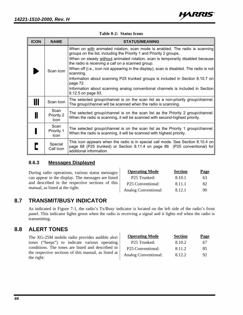
14221-1510-2000, Rev. H
44
Table 8-2: Status Icons
ICON NAME STATUS/MEANING
Scan Icon
When on with animated rotation, scan mode is enabled. The radio is scanning groups on the list, including the Priority 1 and Priority 2 groups. When on steady without animated rotation, scan is temporarily disabled because the radio is receiving a call on a scanned group. When off (i.e., icon not appearing in the display), scan is disabled. The radio is not scanning. Information about scanning P25 trunked groups is included in Section 8.10.7 on page 72. Information about scanning analog conventional channels is included in Section 8.12.5 on page 93.
Scan Icon The selected group/channel is on the scan list as a non-priority group/channel. The group/channel will be scanned when the radio is scanning.
Scan Priority 2
Icon
The selected group/channel is on the scan list as the Priority 2 group/channel. When the radio is scanning, it will be scanned with second-highest priority.
Scan Priority 1
Icon
The selected group/channel is on the scan list as the Priority 1 group/channel. When the radio is scanning, it will be scanned with highest priority.
Special
Call Icon
This icon appears when the radio is in special call mode. See Section 8.10.4 on page 68 (P25 trunked) or Section 8.11.4 on page 86 (P25 conventional) for additional information.
8.6.3 Messages Displayed
During radio operations, various status messages can appear in the display. The messages are listed and described in the respective sections of this manual, as listed at the right:
Operating Mode Section Page P25 Trunked: 8.10.1 63
P25 Conventional: 8.11.1 82 Analog Conventional: 8.12.1 90
8.7 TRANSMIT/BUSY INDICATOR As indicated in Figure 7-1, the radio’s Tx/Busy indicator is located on the left side of the radio’s front panel. This indicator lights green when the radio is receiving a signal and it lights red when the radio is transmitting.
8.8 ALERT TONES The XG-25M mobile radio provides audible alert tones (“beeps”) to indicate various operating conditions. The tones are listed and described in the respective sections of this manual, as listed at the right:
Operating Mode Section Page P25 Trunked: 8.10.2 67
P25 Conventional: 8.11.2 85 Analog Conventional: 8.12.2 92
14221-1510-2000, Rev. H
45
8.9 COMMON OPERATIONS
8.9.1 Turning the Radio On/ Off and Adjusting Volume To turn on the radio, rotate its Power On/Off/Volume control clockwise out of the detent position. Some radio installations may be wired so an external switch such as the vehicle’s ignition key must also be placed in a run or on position before the radio will turn on. When the radio is on, indications appear in the display, such as the selected group/channel and status icons. The radio may be programmed to power-up on the previously selected radio system and group/channel (that was selected at the last power down), or to a pre-programmed radio system and group/channel. It may also be programmed to sound an audible tone (“beep”) at turn on.
Rotate this control clockwise to increase the volume of receive audio and rotate it counter-clockwise to decrease the volume. Volume adjustment can be made at anytime during radio operation, as needed.
To turn the radio off, rotate this control fully counter-clockwise until it clicks. The radio turns completely off within a few seconds of this action.
8.9.2 Programmable Functions
8.9.2.1 Programmable Buttons All buttons on the front panel of the radio can be “remapped” (i.e., reprogrammed) to any primary function. Typically, only the A, B, C and/or OPT buttons are remapped.
The radio ships from the factory with default button function mapping. Configuration changes can be made by radio system administration personnel prior to deployment of the radio. If changes are made from the default mappings, it is recommended that the form in Section 9 be filled-out for future reference.
8.9.2.2 Programmable Menus Many functions can also be programmed to a menu by the radio system administration personnel. The radio has two menus—a trunked menu and a conventional menu. For additional information see Section 8.9.11 on page 55.
8.9.2.3 List of Functions ALARM External Alarm 1 — This function toggles the first external alarm on and off. This alarm
indicates the radio is receiving a trunked mode individual call, or a T99 decoded call in conventional mode.
ALARM2 External Alarm 2 — This function toggles the second external alarm on and off. This external alarm indicates the radio is receiving a trunked mode individual call, or a T99 decoded call in conventional mode.
ALT HOOK Alternate Hookswitch — This function provides a hookswitch function, in addition to the microphone’s rear-panel hookswitch.
ALT PTT Alternate PTT — Sets button used as a PTT switch, in addition to the PTT button located on the side of the microphone.
AUX 1/AUX 2 Auxiliary 1 and Auxiliary 2 — The buttons programmed with these two functions are used to control the first and second auxiliary outputs. For example, the AUX 1 function could be configured and wired to turn a siren on and off, and the AUX 2 function could be configured and wired to turn a light bar on and off.
14221-1510-2000, Rev. H
46
BACKLGHT Backlight Adjustment — This function accesses the display and button backlight intensity level adjustment sub-menu. See Section 8.9.5 on page 52 for respective menu operations.
CG SEL Channel Guard Selection — This function accesses the Channel Guard selection sub-menu, which allows changing of the receive and/or transmit Channel Guard frequencies/codes.
CMD MUTE Command Mute — This function mutes all radio audio until the respective button is pressed again or until the radio receives an individual call (I-call).
CONTRAST Contrast Adjustment — This function accesses the contrast sub-menu, so display contrast adjustments can be made. See Section 8.9.6 on page 52 for respective menu operations.
DEL MAIL Delete Mail — This function deletes all stored radio Radio TextLink messages.
DISP KEY Display Key — This function activates the display of the encrypted key storage location numbers programmed for the selected system. Use the ramp buttons to view the numbers for the selected group or channel.
DISPLAY Display Key ID/Status — This function is used to display the encryption key ID number, and whether or not the respective key is valid and available.
ECP1 SCAN ECP Conventional Priority Scan — This function toggles the Conventional Priority Scan feature on and off. This feature is available for EDACS, ProVoice and P25 trunked radio systems/modes. See Section 8.10.13 on page 80 for additional information.
EMER Emergency Declare — This function causes an emergency to be declared according to radio programming.
ENC1 Tone Encode 1 — This function sends the tone encode programmed for sequence A.
ENC2 Tone Encode 2 — This function sends the tone encode programmed for sequence B.
EXT PTT External PTT — This function provides an external Push-To-Talk function.
EXT SPKR External Speaker — If it is present, this function toggles the external speaker on and off. The external speaker is an optional speaker, typically located outside of the vehicle. It is wired to the mobile radio and it broadcasts the radio’s receive audio when this function is on/enabled.
FCC MENU FCC Menu — This function accesses the FCC sub-menu which provides radio and radio system diagnostic information.
FEATURES Feature Encryption Display — This function accesses the radio’s feature encryption display which displays a list of available features. See Section 8.9.12 on page 58 for additional information.
FREQEDIT Frequency Edit — This function allows editing of a conventional channel’s parameters. This encrypted feature/function is only available to qualified customers.
GRP Group/Channel Select — This function accesses the group/channel select mode so a new trunked group or conventional channel can be selected. For additional information, refer to the second subsection in Section 8.9.8.3 (begins on page 54).
GRP DWN Group/Channel Down — This function decrements the selected group/channel by one (1).
GRP UP Group/Channel Up — This function increments the selected group/channel by one (1).
14221-1510-2000, Rev. H
47
HOME Home — This function returns the radio to the home system/channel on a conventional system, or to the home group on a trunked system. The exact system and group/channel is programmed by the radio system administration personnel prior to deployment of the radio.
HOOK SW Hookswitch — This function performs the programmed hookswitch action. Also see I HOOKSW.
I HOOKSW Inverted Hookswitch — This function performs the programmed hookswitch action with inverted logic. Also see HOOK SW.
INDV Individual Call — This function accesses the individual call list.
LAST SG Last System and Group — This function returns the radio to the last system/channel (conventional systems) or to the last system/group (trunked systems) prior to activating the Home function.
MAC1-MAC10 Macro 1 through Macro 10 — These ten (10) functions execute the corresponding macro, as programmed into the radio.
MAC RST Macro Reset — This function resets all macro mappings back to their original button assignments.
MENU Menu — This function performs the same function as the radio’s MENU button (with default programming). See Section 8.9.11 on page 55 for additional information.
MON CLR Monitor/Clear — In conventional operating mode, this function allows the radio user to monitor the channel for activity. In trunked operating mode, this function causes the current menu operation to exit, including dropping out of calls.
NO DATA No Data/Data — This function toggles the radio’s data feature on and off.
NOIS Noise Blanker — This function toggles the radio’s noise blanker feature on and off.
OPT1 Option 1 — This function executes option 1 per radio personality programming. Option 1 is programmable on a per system basis.
OPT2 Option 2 — This function executes option 2 per radio personality programming. Option 2 is programmable on a per system basis.
P25 VR P25 Vehicular Repeater — This function for the P25 trunked operating mode permits the radio to access a nearby P25 vehicular repeater, so communications can be performed via the vehicular repeater.
PAGE Paging — This function services the paging feature. It allows the radio to transmit pages. A paging call is a control channel ping to a specific radio logical ID (LID) number. A radio will always receive a page call since Rx Page is always enabled. See Section 8.10.15 on page 81.
PHONE Phone — This function accesses the radio’s phone list, so an telephone interconnect call can be performed. For trunked mode, see Section 8.10.8 on page 75 for additional information.
PRESET 1 - 3 Preset 1 through Preset 3 — These functions are used to store and recall user-selected parameters such as scan mode, selected profile, selected talk group, and priority talk group.
PRIVATE Private Mode — This function turns private mode for the currently selected system/group on and off. When on, the radio can transmit encrypted voice. See Section 8.13 on page 101.
14221-1510-2000, Rev. H
48
PROFILE Profile — This function toggles ProFile™ on and off. ProFile provides “over-the-air” personality and feature encryption programming data to the radio. ProFile also includes the ability to remotely read a radio’s serial number. ProFile does not require attachment of an external data device to the radio in order to change its programming/personality.
PROGRAM Programming Mode — This function enables the radio’s personality programming mode.
PTT Push-To-Talk — This function provides a PTT function to key the radio’s transmitter. It performs exactly the same function as the microphone’s PTT button.
PUB ADDR Public Address — This function turns the radio’s Public Address (PA) feature on and off. The radio installation must be wired to a public address speaker in order to support this feature.
RD MAIL Read Mail — This function allows viewing of Radio TextLink messages.
REPTR Repeater — This function accesses an optional conventional vehicular repeater that can be wired to and used with the radio.
REVISION Revision Information — This function displays the radio’s revision information. Once displayed, the +/- buttons can be used to scroll through the displayed information.
RPTR EN Repeater Enable — This function enables and disables an optional conventional vehicular repeater used with the radio.
RWSS Reverse Warm Start — This function allows the radio to send a registration message to the KMF (Key Management Facility) to update the radio encryption keys. It is used when the radio has a UKEK (User Key Encryption Key) but does not have a valid TEK (Traffic Encryption Key), or anytime the radio wants current key information from the KMF.
S/G1 – S/G16 System/Group 1 through System/Group 16 — Each of these 16 functions selects a pre-programmed system/group or channel. Up to 16 trunked system/group and/or conventional system/channel combinations can be defined for the S/G1 through S/G16 functions. When a corresponding button is pressed, the radio changes to the pre-programmed trunked system and group, or to the preprogrammed conventional system and channel.
SCAN Scan — This function toggles scan operation on and off.
SCAN A/D Scan Add/Delete — This toggle-type function adds and deletes groups/channels to and from the scan list.
SCAN ADD Scan Add — This function adds groups/channels to the scan list.
SCAN DEL Scan Delete — This function deletes groups/channels from the scan list. When the radio is scanning, it also provides a Nuisance Delete function.
SL1 - SL8 Siren and Light 1 through Siren and Light 8 — The SL1 through SL8 functions allow control of optional siren/light equipment interfaced to the radio. Each function will activate the pre-defined siren/light action. For example, SL1 could be configured and wired to turn a light bar on and off, and SL2 could be configured and wired to turn a siren on and off.
SL HORN Siren and Light Horn/Ring — This function activates the siren and light horn/ring feature.
SL RESET Siren and Light Reset — This function turns all siren and light combinations off. It effectively resets all siren/light functions to their default states.
SND MAIL Send Mail —This function enables the Radio TextLink message feature.
14221-1510-2000, Rev. H
49
SQUELCH Squelch Adjustment — This conventional mode function enables the squelch adjustment sub-menu so squelch can be adjusted. See Section 8.12.6 on page 96 for the respective menu operation.
STATUS Status Selection — This function accesses the ten (10) status entries (0 through 9), so a status can be selected and transmitted.
STATUS 0 – 9 Status 1 through Status 9 — One of these ten (10) functions, when activated by pressing the corresponding button, selects a status (0 through 9) which transmits a preprogrammed status condition to the currently-selected radio system. This allows selecting of a status condition without having to access the list via the STATUS function.
SYS System Selection — This function is used to enter the system select mode to select a new radio system. For additional information, refer to the second subsection in Section 8.9.7.3 (begins on page 53).
SYS DWN System Down — This function decrements the selected system by one (1).
SYS UP System Up — This function increments the selected system by one (1).
SYS SCAN System Scan — Per personality programming, this function toggles Wide Area System Scan, ProScan™, or 3-Site Scan on and off.
T99 EN Type 99 Tone Decode Enable — This function toggles the Type 99 decode feature on and off. See Section 8.12.7 on page 96 for additional information.
TALKARND Repeater Talk-Around — This conventional channel function toggles repeater talk-around on and off. When operating in conventional mode, talk-around enables the radio to transmit and receive on the same radio frequency. Therefore, the use of a radio repeater/base station is not required. However, the overall communication range may be limited.
TIME TextLink Time — This function displays the time-of-day per the radio TextLink server.
TX POWER Transmitter Power — This function toggles the radio’s transmitter between high and low power. See Section 8.9.10.2 on page 55 for additional information.
WAIL Siren/Light Wail — This function activates the optional siren/light equipment’s wail sound.
YELP Siren/Light Yelp — This function activates the optional siren/light equipment’s yelp sound.
8.9.3 Connecting a Bluetooth Wireless Speaker/Microphone The radio can be programmed so a Bluetooth wireless speaker/microphone or another similar type Blue-tooth wireless audio device can be used with it. If the radio is programmed as such, use the following procedures as necessary:
8.9.3.1 Pairing/Connecting a Bluetooth Wireless Device with the Radio
1. Turn on the Bluetooth wireless device (e.g., wireless speaker/mic) and place it in pairing mode. Consult the device’s operator manual as necessary. Some devices may refer to this mode as “discovery mode.”
Some Bluetooth devices will time-out of their pairing mode after a preset time, so be familiar with the device’s audible and/or visual pairing mode indications, and re-enter pairing mode if this occurs before the radio can be paired with/connected to it.
14221-1510-2000, Rev. H
50
2. Press the radio’s MENU button to activate the menu function.
3. Press the radio’s + or – buttons until BLUTOOTH (for Bluetooth) is selected with the > symbol, and then press MENU to enter this function. ADD DEVICE appears.
If BLUTOOTH does not appear on the current menu, the radio is not programmed for Bluetooth wireless operations in the current menu/mode (i.e., trunked or conventional). Therefore, wireless Bluetooth connections are not possible.
4. With ADD DEVICE displayed, press MENU again. The radio then displays SEARCHING as it begins searching for nearby Bluetooth devices that it can pair/connect with. During the search, the current number of the found Bluetooth devices is displayed and the (Bluetooth) icon blinks in the display.
The (Bluetooth) icon blinks in the display when the radio’s Bluetooth function is on but the radio is not paired with a Bluetooth wireless device.
5. Wait for the search to complete. When done, the radio displays SELECT and the name of the first pairable device located during its search.
6. Press the + or – buttons until the name of the desired wireless Bluetooth device for connection to appears, and then press MENU again to pair/connect to it. PAIR WITH displays, and after several seconds, the pairing completes. This is indicated when radio displays PAIRING COMPLETE and the
(Bluetooth) icon stops blinking and remains on. Also note the device’s audible and/or visual indication per the successful pairing/connection, such as a blue light and/or several high-pitched beeps.
If the name of the desired Bluetooth wireless device was not listed, first verify the device is still in pairing mode (aka., discovery mode), then use the SEARCH AGAIN function, or repeat this procedure from step 1.
If the selected Bluetooth wireless device cannot be successfully paired, PAIRING FAILED displays, followed by ADD DEVICE. In this case, the device has most likely either exited its pairing mode (aka., discovery mode) since the radio’s search feature found it or it has been turned off (either manually or automatically). Correct as necessary and then use the ADD DEVICE function to perform another search.
8.9.3.2 Basic Bluetooth Wireless Device Operations After successful pairing/connection, radio receive audio and alert tones are routed to the speaker/earpiece of the Bluetooth wireless device instead of to the radio’s (internal/external) speaker, and the radio’s previously active (internal/external) speaker remains muted. Volume control adjustments for the wireless device are made at the device, not at the radio’s control head.
The PTT switch of the standard/wired microphone connected to the control head remains active when a Bluetooth device is actively paired with the radio. The radio can be keyed from this PTT switch; however, transmit audio will be sourced from the microphone of the Bluetooth wireless device.
NOTE
NOTE
NOTE
14221-1510-2000, Rev. H
51
After being paired with a Bluetooth wireless device, if the radio or the device is powered off and then back on, pairing will be automatically re-established a short time after power-up. This assumes the device is within wireless range of the radio.
Refer to the Bluetooth wireless device’s operator manual for additional information about using it with the radio.
8.9.3.3 Deleting/Disconnecting a Bluetooth Wireless Device To disconnect a currently connected Bluetooth wireless device, or to prevent the previously-connected device from re-connecting to the radio, follow this procedure. In the latter case, the device does not need to be actively paired/connected with the radio before beginning this procedure:
1. Press the radio’s MENU button to activate the menu function.
2. Press the radio’s + or – buttons until BLUTOOTH is selected with the > symbol, and then press MENU to enter this function. ADD DEVICE appears.
3. Press the radio’s + or – buttons until DELETE appears, followed by the device’s name.
4. Press the MENU button to delete/disconnect the Bluetooth device.
Otherwise, press the CLR (Clear) button to cancel, or simply wait for this menu operation to time-out. Upon successfully deleting/disconnecting the device, the radio’s (Bluetooth) icon begins blinking in the display, indicating this function is still on, but no device is currently connected to the radio.
8.9.3.4 Turning Bluetooth Off Follow this procedure to turn off the radio’s Bluetooth wireless feature. When turned off, a currently connected device will be disconnected. Also, no Bluetooth devices can pair/connect with the radio:
1. Press the radio’s MENU button to activate the menu function.
2. Press the radio’s + or – buttons until BLUTOOTH is selected with the > symbol, and then press MENU to enter this function. ADD DEVICE appears.
3. Press the radio’s + or – buttons until TURN OFF BLUETOOTH appears, and then press the MENU button again. The radio immediately disconnects the previously connected Bluetooth device, and its
(Bluetooth) icon disappears.
8.9.4 Locking and Unlocking the Front Panel Buttons Some buttons on the front panel can be disabled to prevent accidental activation by “locking” them. Locking and unlocking is a toggle-type function. To lock the buttons:
1. Press the MENU button to activate the menu function.
2. Within one (1) second, press the OPT button. LOCKED displays when the buttons lock.
To unlock the buttons, repeat the process. UNLOCKED displays when the buttons unlock.
Locking can also be performed with the KEY LOCK menu function, if this function is programmed on a radio menu. See Section 8.9.11 for additional information.
Unlocking can only be performed with the MENU and OPT buttons, as described above.
14221-1510-2000, Rev. H
52
8.9.5 Display and Button Backlight Adjustment If backlight adjustment function is programmed on a radio menu, backlight intensity level can be adjusted as follows:
1. Press the MENU button to activate the menu function. The programmed menu functions appear in the display. The > symbol at the left of a menu function indicates the currently selected function.
Alternately, if another button such as one (1) of the three (3) preset buttons is programmed with the Backlight function, press this button and advance to step 4.
2. Press the + or – buttons to until BACKLGHT (for backlight) is selected with the > symbol.
3. Press the MENU button again to select the backlight menu.
4. Press the + or – buttons to select a new backlight intensity level. Selections are OFF (no backlighting) and 1 though 6, with 6 being the brightest backlight intensity level.
5. Press the MENU button again to save the new backlight intensity level and return to a normal group/channel display indication.
8.9.6 Display Contrast Adjustment If the contrast adjustment function is programmed on a radio menu, the display contrast level can be adjusted as follows:
1. Press the MENU button to activate the menu function. The programmed menu functions appear in the display. The > symbol at the left of a menu function indicates the currently selected function.
Alternately, if another button such as one (1) of the three (3) preset buttons is programmed with the Contrast function, press this button and advance to step 4.
2. Press the + or – buttons to until CONTRAST is selected with the > symbol.
3. Press the MENU button again to select the contrast menu.
4. Press the + or – buttons to select a new contrast level between 1 and 8.
5. Press the MENU button again to save the new contrast level and return to a normal group/channel display indication.
8.9.7 System Selection Several different radio system selection methods exists based upon radio programming.
8.9.7.1 +/– Buttons Select System If the + and – buttons are programmed for radio system selection, when the radio is at a normal group/channel display (i.e., not in a menu), press either button to select a different system. The name of the selected system appears in the top line of the display, except during menu operations.
14221-1510-2000, Rev. H
53
8.9.7.2 System/Group/Channel Control Selects System If the System/Group/Channel control is programmed for radio system selection, rotate this control to select a different system. The name of the selected system appears in the top line of the display, except during menu operations.
8.9.7.3 Selecting a System with the System Selection (SYS) Function If the System Selection (SYS) function is programmed to a radio button or menu, a different radio system can be selected using one of the following methods. This function can be programmed to the trunked menu, to the conventional menu, or to both menus:
System Selection Function Programmed to a Menu
1. Press the MENU button to activate the menu function. The programmed menu functions appear in the display. The > symbol at the left of a menu function indicates the currently selected function.
2. Press the + or – buttons to scroll until SYS is selected with the > symbol.
3. Press the MENU button again to select this function. SYS = x displays, where x is the number of the currently selected radio system, as programmed into the radio.
4. Press the + or – buttons to scroll and select another radio system, as programmed into the radio. The radio system’s name appears in the top line of the display, and its number follows SYS =.
5. When the desired system is displayed, press the MENU button again to change to it. Optionally, wait and the radio will automatically change to the displayed system.
To cancel out of this operation at anytime and return to the original system, press the CLR button.
System Selection Function Programmed to a Button
1. Press the button programmed with the System Selection function. SYS = x displays, where x is the number of the currently selected radio system, as programmed into the radio.
2. Press the + or – buttons to scroll and select another radio system, as programmed into the radio. The radio system’s name appears in the top line of the display, and its number follows SYS =.
3. When the desired system is displayed, press the MENU button again to change to it. Optionally, wait and the radio will automatically change to the displayed system.
To cancel out of this operation at anytime and return to the original system, press the CLR button.
8.9.8 Group/Channel Selection Several different group/channel selection methods exists based upon radio programming.
8.9.8.1 System/Group/Channel Control Selects Groups/Channels If the System/Group/Channel control is programmed for group/channel selection, rotate this control to select a different group or channel. The name of the selected group/channel appears in the middle line of the display in large characters.
14221-1510-2000, Rev. H
54
8.9.8.2 +/– Buttons Select Groups/Channels If the + and – buttons are programmed for group/channel selection and the radio is at a normal group/channel display (i.e., not in a menu), press either button to select a different group/channel. The name of the selected group/channel appears in the middle line of the display in large characters.
Any radio button may be programmed for system or group/channel selection. Consult with the radio system’s network administration personnel for programming information for a specific radio.
8.9.8.3 Selecting a Group/Channel with the Group/Channel Selection (GRP) Function
If the Group/Channel Selection (GRP) function is programmed to a radio button or menu, a different group or channel can be selected using one of the following methods. This function can be programmed to the trunked menu, to the conventional menu, or to both menus:
Group/Channel Selection Function Programmed to a Menu
1. Press the MENU button to activate the menu function. The programmed menu functions appear in the display. The > symbol at the left of a menu function indicates the currently selected function.
2. Press the + or – buttons to scroll until GRP is selected with the > symbol.
3. Press the MENU button again to select this function. If operating on a trunked system, GRP = x displays, where x is the number of the currently selected group, as programmed into the radio. If operating on a conventional system, CHN = x displays, where x is the number of the currently selected channel, as programmed into the radio.
4. Press the + or – buttons to scroll and select another group/channel, as programmed into the radio. The group/channel name displays. During group selection, its number, as programmed, follows GRP =. During channel selection its number, as programmed, follows CHN =.
5. When the desired group/channel is displayed, press the MENU button again to change to it. Optionally, wait and the radio will automatically change to the displayed group/channel.
To cancel out of this operation at anytime and return to the original system, press the CLR button.
Group/Channel Selection Function Programmed to a Button
1. Press the button programmed with the Group/Channel Selection (GRP) function. If operating on a trunked system, GRP = x displays, where x is the number of the currently selected group, as programmed into the radio. If operating on a conventional system, CHN = x displays, where x is the number of the currently selected channel, as programmed into the radio.
2. Press the + or – buttons to scroll and select another group/channel, as programmed into the radio. The group/channel name displays. During group selection, its number, as programmed, follows GRP =. During channel selection its number, as programmed, follows CHN =.
3. When the desired group/channel is displayed, press the MENU button again to change to it. Optionally, wait and the radio will automatically change to the displayed group/channel.
To cancel out of this operation at anytime and return to the original system, press the CLR button.
NOTE
14221-1510-2000, Rev. H
55
8.9.9 Selecting a System and a Group/Channel With The System/Group (SG) Function
The radio’s system/group selection function allows 1 of up to 16 programmed system and group/channel combinations to be selected via a single button press or menu selection. This function can be programmed to the trunked menu or to the conventional menu or to both menus. To change to the particular system and group/channel, press the respective programmed button or select the desired system/group/channel combination (SG1 through SG16) programmed on a menu.
8.9.10 Transmit Power Level Adjustment The radio has two transmit power levels: high and low. Using the low transmit power level, when possible, can help reduce or prevent unnecessary radio interference on nearby radio frequencies.
If the TX POWER menu function is programmed into the radio, the radio’s transmit power level can be switched between low and high as described in the following subsections. For a trunked radio system, the power level is adjustable on a per-system basis. For a conventional radio system, the power level is adjustable on a per-channel basis.
When the low transmit power level is selected, the status icon appears at the bottom of the display and LOW PWR briefly appears at the top. When the high transmit power level is selected, the status icon does not appear at the bottom of the display and HIGH PWR briefly appears at the top.
The previously set power level is maintained after a channel change and after a radio system change.
8.9.10.1 Tx Power Adjustment via the Menu
1. Press the MENU button to activate the menu function. The programmed menu functions appear in the display. The > symbol at the left of a menu function indicates the currently selected function.
2. Press the + or – buttons to scroll until TX POWER is selected with the > symbol.
3. Press the MENU button again to toggle the transmit power level to the other level. For example, if the radio was in the high power level, it will change to a low power level.
8.9.10.2 Tx Power Adjustment via a Programmed Button Any button on the radio’s front panel can be programmed to toggle the transmit power level when it is pressed. For example, one of the three (3) preset buttons (A, B, or C) may be programmed with this function. If so, press that button to toggle the power level between low and high. The status icon displays when low transmit power level is selected. Consult with the radio system administration personnel as necessary to determine which button is programmed with this function, if any.
8.9.11 Menu Operations The radio’s menu function accesses features that are not directly available by a single button stroke. Menu functions available and the order of menu functions are configurable via radio programming. There are two menus—a trunked menu and a conventional menu. The trunked menu is active when a trunked radio system (e.g., P25 trunked) is selected and the conventional menu is active when a conventional radio system is selected. Each menu can have up to 20 different functions. Menu functions are listed and described in Table 8-3.
After a radio power-up, the menu function that is at the top of the programmed menu list will always be displayed first when the MENU button is pressed. Subsequent access to the menu will return the last menu function that was shown in the display and cursor position. Basic menu operation:
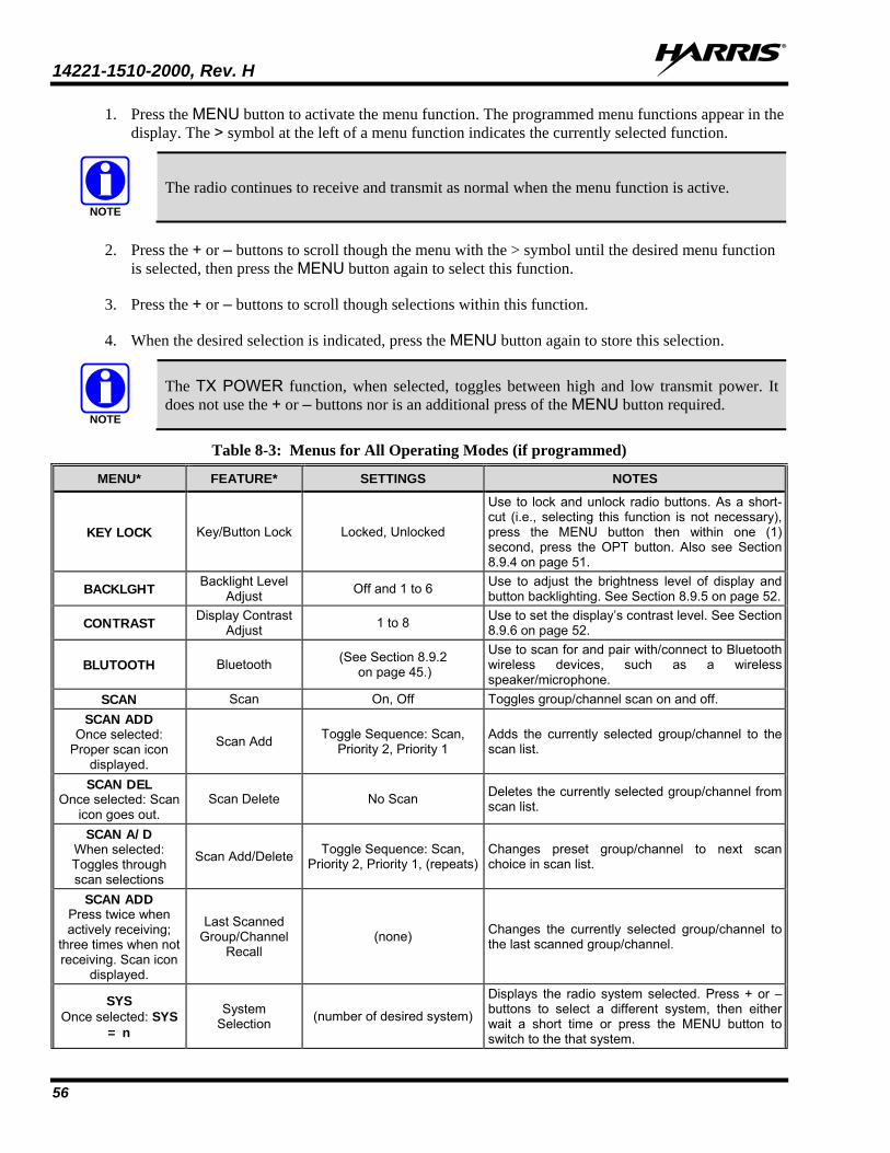
14221-1510-2000, Rev. H
56
1. Press the MENU button to activate the menu function. The programmed menu functions appear in the display. The > symbol at the left of a menu function indicates the currently selected function.
The radio continues to receive and transmit as normal when the menu function is active.
2. Press the + or – buttons to scroll though the menu with the > symbol until the desired menu function is selected, then press the MENU button again to select this function.
3. Press the + or – buttons to scroll though selections within this function.
4. When the desired selection is indicated, press the MENU button again to store this selection.
The TX POWER function, when selected, toggles between high and low transmit power. It does not use the + or – buttons nor is an additional press of the MENU button required.
Table 8-3: Menus for All Operating Modes (if programmed)
MENU* FEATURE* SETTINGS NOTES
KEY LOCK Key/Button Lock Locked, Unlocked
Use to lock and unlock radio buttons. As a short-cut (i.e., selecting this function is not necessary), press the MENU button then within one (1) second, press the OPT button. Also see Section 8.9.4 on page 51.
BACKLGHT Backlight Level Adjust Off and 1 to 6 Use to adjust the brightness level of display and
button backlighting. See Section 8.9.5 on page 52.
CONTRAST Display Contrast Adjust 1 to 8 Use to set the display’s contrast level. See Section
8.9.6 on page 52.
BLUTOOTH Bluetooth (See Section 8.9.2 on page 45.)
Use to scan for and pair with/connect to Bluetooth wireless devices, such as a wireless speaker/microphone.
SCAN Scan On, Off Toggles group/channel scan on and off. SCAN ADD
Once selected: Proper scan icon
displayed.
Scan Add Toggle Sequence: Scan, Priority 2, Priority 1
Adds the currently selected group/channel to the scan list.
SCAN DEL Once selected: Scan
icon goes out. Scan Delete No Scan Deletes the currently selected group/channel from
scan list.
SCAN A/D When selected: Toggles through scan selections
Scan Add/Delete Toggle Sequence: Scan, Priority 2, Priority 1, (repeats)
Changes preset group/channel to next scan choice in scan list.
SCAN ADD Press twice when actively receiving;
three times when not receiving. Scan icon
displayed.
Last Scanned Group/Channel
Recall (none) Changes the currently selected group/channel to
the last scanned group/channel.
SYS Once selected: SYS
= n
System Selection (number of desired system)
Displays the radio system selected. Press + or – buttons to select a different system, then either wait a short time or press the MENU button to switch to the that system.
NOTE
NOTE
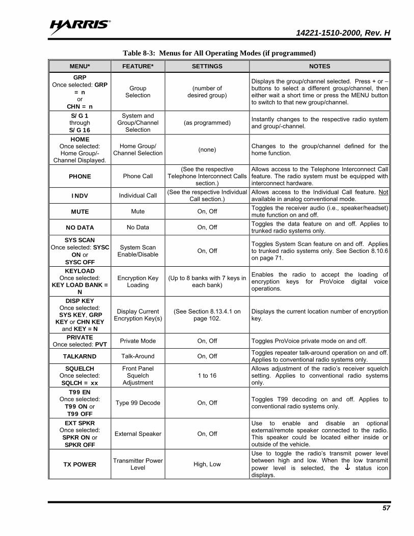
14221-1510-2000, Rev. H
57
Table 8-3: Menus for All Operating Modes (if programmed)
MENU* FEATURE* SETTINGS NOTES
GRP Once selected: GRP
= n or
CHN = n
Group Selection
(number of desired group)
Displays the group/channel selected. Press + or – buttons to select a different group/channel, then either wait a short time or press the MENU button to switch to that new group/channel.
S/G 1 through S/G 16
System and Group/Channel
Selection (as programmed) Instantly changes to the respective radio system
and group/-channel.
HOME Once selected: Home Group/-
Channel Displayed.
Home Group/ Channel Selection (none) Changes to the group/channel defined for the
home function.
PHONE Phone Call (See the respective
Telephone Interconnect Calls section.)
Allows access to the Telephone Interconnect Call feature. The radio system must be equipped with interconnect hardware.
INDV Individual Call (See the respective Individual Call section.)
Allows access to the Individual Call feature. Not available in analog conventional mode.
MUTE Mute On, Off Toggles the receiver audio (i.e., speaker/headset) mute function on and off.
NO DATA No Data On, Off Toggles the data feature on and off. Applies to trunked radio systems only.
SYS SCAN Once selected: SYSC
ON or SYSC OFF
System Scan Enable/Disable On, Off
Toggles System Scan feature on and off. Applies to trunked radio systems only. See Section 8.10.6 on page 71.
KEYLOAD Once selected:
KEY LOAD BANK = N
Encryption Key Loading
(Up to 8 banks with 7 keys in each bank)
Enables the radio to accept the loading of encryption keys for ProVoice digital voice operations.
DISP KEY Once selected:
SYS KEY, GRP KEY or CHN KEY
and KEY = N
Display Current Encryption Key(s)
(See Section 8.13.4.1 on page 102.
Displays the current location number of encryption key.
PRIVATE Once selected: PVT Private Mode On, Off Toggles ProVoice private mode on and off.
TALKARND Talk-Around On, Off Toggles repeater talk-around operation on and off. Applies to conventional radio systems only.
SQUELCH Once selected: SQLCH = xx
Front Panel Squelch
Adjustment 1 to 16
Allows adjustment of the radio’s receiver squelch setting. Applies to conventional radio systems only.
T99 EN Once selected:
T99 ON or T99 OFF
Type 99 Decode On, Off Toggles T99 decoding on and off. Applies to conventional radio systems only.
EXT SPKR Once selected: SPKR ON or SPKR OFF
External Speaker On, Off
Use to enable and disable an optional external/remote speaker connected to the radio. This speaker could be located either inside or outside of the vehicle.
TX POWER Transmitter Power Level High, Low
Use to toggle the radio’s transmit power level between high and low. When the low transmit power level is selected, the status icon displays.
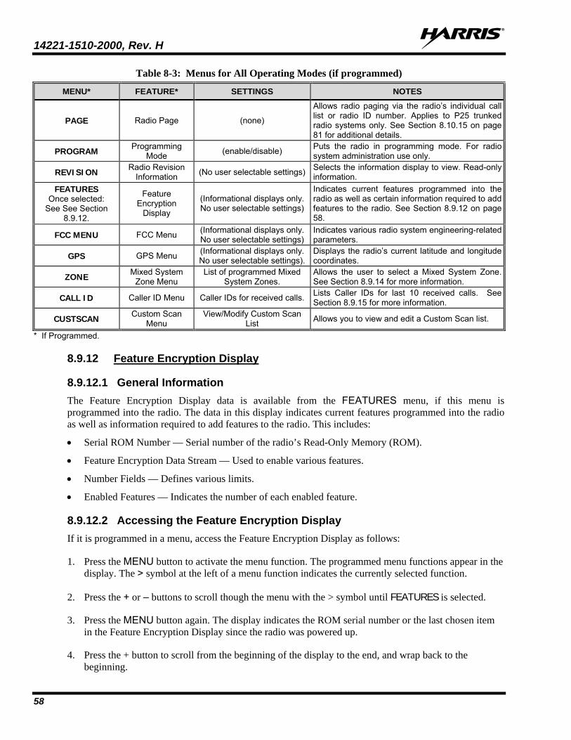
14221-1510-2000, Rev. H
58
Table 8-3: Menus for All Operating Modes (if programmed)
MENU* FEATURE* SETTINGS NOTES
PAGE Radio Page (none)
Allows radio paging via the radio’s individual call list or radio ID number. Applies to P25 trunked radio systems only. See Section 8.10.15 on page 81 for additional details.
PROGRAM Programming Mode (enable/disable) Puts the radio in programming mode. For radio
system administration use only.
REVISION Radio Revision Information (No user selectable settings) Selects the information display to view. Read-only
information. FEATURES
Once selected: See See Section
8.9.12.
Feature Encryption
Display
(Informational displays only. No user selectable settings)
Indicates current features programmed into the radio as well as certain information required to add features to the radio. See Section 8.9.12 on page 58.
FCC MENU FCC Menu (Informational displays only. No user selectable settings)
Indicates various radio system engineering-related parameters.
GPS GPS Menu (Informational displays only. No user selectable settings).
Displays the radio’s current latitude and longitude coordinates.
ZONE Mixed System Zone Menu
List of programmed Mixed System Zones.
Allows the user to select a Mixed System Zone. See Section 8.9.14 for more information.
CALL ID Caller ID Menu Caller IDs for received calls. Lists Caller IDs for last 10 received calls. See Section 8.9.15 for more information.
CUSTSCAN Custom Scan Menu
View/Modify Custom Scan List Allows you to view and edit a Custom Scan list.
* If Programmed.
8.9.12 Feature Encryption Display
8.9.12.1 General Information The Feature Encryption Display data is available from the FEATURES menu, if this menu is programmed into the radio. The data in this display indicates current features programmed into the radio as well as information required to add features to the radio. This includes:
• Serial ROM Number — Serial number of the radio’s Read-Only Memory (ROM).
• Feature Encryption Data Stream — Used to enable various features.
• Number Fields — Defines various limits.
• Enabled Features — Indicates the number of each enabled feature.
8.9.12.2 Accessing the Feature Encryption Display If it is programmed in a menu, access the Feature Encryption Display as follows:
1. Press the MENU button to activate the menu function. The programmed menu functions appear in the display. The > symbol at the left of a menu function indicates the currently selected function.
2. Press the + or – buttons to scroll though the menu with the > symbol until FEATURES is selected.
3. Press the MENU button again. The display indicates the ROM serial number or the last chosen item in the Feature Encryption Display since the radio was powered up.
4. Press the + button to scroll from the beginning of the display to the end, and wrap back to the beginning.
14221-1510-2000, Rev. H
59
8.9.12.3 Serial ROM Number (12 Hexadecimal Digits) Within the Feature Encryption Display, the serial number stored in the radio’s ROM is indicated after first entering the display. This serial number is 12 hexadecimal digits in length.
To enable a feature in the radio, record this serial number and call and report it to the Harris Technical Assistance Center (TAC), along with other pertinent information. TAC contact information is listed in Section 11.2 of this manual.
8.9.12.4 Feature Encryption Data Stream These data streams define the features currently enabled in the radio. They are required by Harris to enable other features. There are three (3) data streams: FD1, FD2, FD3, and FD4. All four are required.
8.9.12.5 Number Fields The number fields show the existing limits of the radio as follows:
• CNVCHN# XXX — Where XXX is the maximum number of conventional channels that can be programmed into the radio.
• SYSGRP# XXX — Where XXX is the maximum number of systems and group combinations that can be programmed into the radio.
• TRKSYS# XXX — Where XXX is the maximum number of trunked systems that can be programmed into the radio.
The above limits of the radio should be known before attempting to program other systems, groups, and conventional channels, and before attempting to enable other radio features via radio programming.
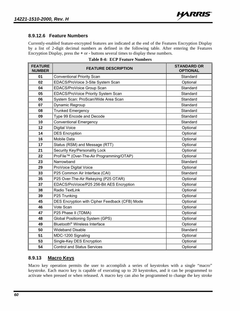
14221-1510-2000, Rev. H
60
8.9.12.6 Feature Numbers Currently-enabled feature-encrypted features are indicated at the end of the Features Encryption Display by a list of 2-digit decimal numbers as defined in the following table. After entering the Features Encryption Display, press the + or - buttons several times to display these numbers.
Table 8-4: ECP Feature Numbers FEATURE NUMBER FEATURE DESCRIPTION STANDARD OR
OPTIONAL 01 Conventional Priority Scan Standard 02 EDACS/ProVoice 3-Site System Scan Optional 04 EDACS/ProVoice Group Scan Standard 05 EDACS/ProVoice Priority System Scan Standard 06 System Scan: ProScan/Wide Area Scan Standard 07 Dynamic Regroup Standard 08 Trunked Emergency Standard 09 Type 99 Encode and Decode Standard 10 Conventional Emergency Standard 12 Digital Voice Optional 14 DES Encryption Optional 16 Mobile Data Optional 17 Status (RSM) and Message (RTT) Optional 21 Security Key/Personality Lock Optional 22 ProFile™ (Over-The-Air Programming/OTAP) Optional 23 Narrowband Standard 29 ProVoice Digital Voice Optional 33 P25 Common Air Interface (CAI) Standard 35 P25 Over-The-Air Rekeying (P25 OTAR) Optional 37 EDACS/ProVoice/P25 256-Bit AES Encryption Optional 38 Radio TextLink Optional 39 P25 Trunking Optional 45 DES Encryption with Cipher Feedback (CFB) Mode Optional 46 Vote Scan Optional 47 P25 Phase II (TDMA) Optional 48 Global Positioning System (GPS) Optional 49 Bluetooth® Wireless Interface Optional 50 Wideband Disable Standard 51 MDC-1200 Signaling Optional 53 Single-Key DES Encryption Optional 54 Control and Status Services Optional
8.9.13 Macro Keys Macro key operation permits the user to accomplish a series of keystrokes with a single “macro” keystroke. Each macro key is capable of executing up to 20 keystrokes, and it can be programmed to activate when pressed or when released. A macro key can also be programmed to change the key stroke
14221-1510-2000, Rev. H
61
sequence the next time it is activated. For detailed operation and assignment of macro keys, consult with the radio system’s network administration personnel for programming information for the specific radio.
8.9.14 Mixed System Zones A Zone is a grouping of analog conventional channels, P25 conventional channels, and/or P25T or P25C talkgroups. Mixed System Zones are defined in RPM and can be comprised of any combination of channels/groups from multiple systems as long as the system definitions share the same WACN/System ID. If a Mixed System Zone is not configured in RPM, it will not appear on the radio. Up to 50 Mixed System Zones can be defined.
To select a Mixed System Zone:
1. Press MENU.
2. Scroll through menu and select ZONE.
3. Select the desired Mixed System Zone.
4. Alternately, the System/Group/Channel knob or a button on the control head can be programmed to scroll through available Mixed System Zones.
When scan is enabled on a system in a Mixed System Zone, the radio continues to display the zone name or system name per the current radio mode (system/zone). When toggling scan ON/OFF, there is no change one line 1 of the radio display. If it is showing system name, it continues to show system name; if it is showing zone name, it continues to show the zone name during scanning.
8.9.15 Mixed Zone Scan The Mixed Zone Scan (MZS) feature gives the user the capability to scan based on a custom scan list that is assigned at the system level. The Custom Scan (CS) list can contain System and Channel/Group configurations across P25 Trunk, P25 Conventional, and Analog Systems. When a Custom Scan List is defined on a P25T system, the radio can scan P25T, P25C and Analog systems. When defined on a P25C or Analog system, the radio only scans conventional channels. MZS also gives the user the capability to scan beyond the selected system group set.
• P25T Scan
When a custom scan list is assigned to a P25T system, the user has the ability to scan P25T, P25C, and Analog groups/channels. All P25T systems must have the same WACN, System ID, and Unit ID to be added to the custom scan list.
• P25C and Analog Scan
When a custom scan lists is assigned to a P25C or Analog System, the user has the ability to scan P25C and Analog channels. P25T systems are ignored.
8.9.15.1 Custom Scan List Selection The Custom Scan List is assigned at the System level. Scanning protocols (Custom Scan, System Scan, and Conventional Priority Scan) are mutually exclusive. Once a custom scan list is assigned to a system, when you enable scan, you are scanning the channel/groups defined in the custom scan list. A Custom Scan List can be assigned to a system through RPM only. The radio supports up to 10 Custom Scan lists, with up to 50 channels/groups in each.

14221-1510-2000, Rev. H
62
8.9.15.2 View Custom Scan Lists
Scan must be off to view a Custom Scan List.
1. From the radio menu, select CUSTSCAN.
2. Select the desired group/channel from the Custom Scan list. Options available for each channel/group include:
• View the channel’s/group’s scan priority.
• Delete the channel/group from the scan list.
• Nuisance delete the channel/group.
3. Press the Option button to back up one display; press the Clear button to return to the home screen.
8.9.15.3 Edit Custom Scan Lists
Scan must be off to edit a Custom Scan List.
1. From the radio menu, select CUSTSCAN.
2. Select EDIT LST.
3. Select the desired system from the list.
4. Select the desired channel group. Scroll through available options:
• Add the channel/group to the scan list.
• Change the channel’s/group’s scan priority.
• Delete the channel/group from the scan list.
• Nuisance delete the channel/group.
5. Press the Option button to back up one display; press the Clear button to return to the home screen.
8.9.16 Caller ID This feature allows you to view the caller ID or alias for up to the last 10 received calls. Received calls include Group, Announcement, Phone, Patch, SimulSelect, Agency, Fleet, and MDC.
1. Press MENU and scroll through the menu to select CALL ID. Alternately, a button on the control head can be programmed to access the CALL ID list.
2. Scroll through available entries. The most recent call is displayed at the top of the list. “NO ENTRY” is displayed if there are no entries.
NOTE
NOTE
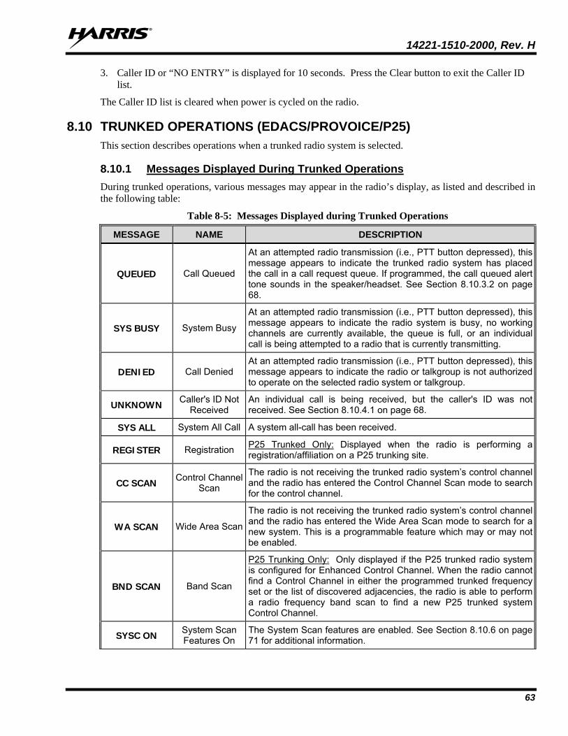
14221-1510-2000, Rev. H
63
3. Caller ID or “NO ENTRY” is displayed for 10 seconds. Press the Clear button to exit the Caller ID list.
The Caller ID list is cleared when power is cycled on the radio.
8.10 TRUNKED OPERATIONS (EDACS/PROVOICE/P25) This section describes operations when a trunked radio system is selected.
8.10.1 Messages Displayed During Trunked Operations During trunked operations, various messages may appear in the radio’s display, as listed and described in the following table:
Table 8-5: Messages Displayed during Trunked Operations
MESSAGE NAME DESCRIPTION
QUEUED Call Queued
At an attempted radio transmission (i.e., PTT button depressed), this message appears to indicate the trunked radio system has placed the call in a call request queue. If programmed, the call queued alert tone sounds in the speaker/headset. See Section 8.10.3.2 on page 68.
SYS BUSY System Busy
At an attempted radio transmission (i.e., PTT button depressed), this message appears to indicate the radio system is busy, no working channels are currently available, the queue is full, or an individual call is being attempted to a radio that is currently transmitting.
DENIED Call Denied At an attempted radio transmission (i.e., PTT button depressed), this message appears to indicate the radio or talkgroup is not authorized to operate on the selected radio system or talkgroup.
UNKNOWN Caller's ID Not Received
An individual call is being received, but the caller's ID was not received. See Section 8.10.4.1 on page 68.
SYS ALL System All Call A system all-call has been received.
REGISTER Registration P25 Trunked Only: Displayed when the radio is performing a registration/affiliation on a P25 trunking site.
CC SCAN Control Channel Scan
The radio is not receiving the trunked radio system’s control channel and the radio has entered the Control Channel Scan mode to search for the control channel.
WA SCAN Wide Area Scan
The radio is not receiving the trunked radio system’s control channel and the radio has entered the Wide Area Scan mode to search for a new system. This is a programmable feature which may or may not be enabled.
BND SCAN Band Scan
P25 Trunking Only: Only displayed if the P25 trunked radio system is configured for Enhanced Control Channel. When the radio cannot find a Control Channel in either the programmed trunked frequency set or the list of discovered adjacencies, the radio is able to perform a radio frequency band scan to find a new P25 trunked system Control Channel.
SYSC ON System Scan Features On
The System Scan features are enabled. See Section 8.10.6 on page 71 for additional information.
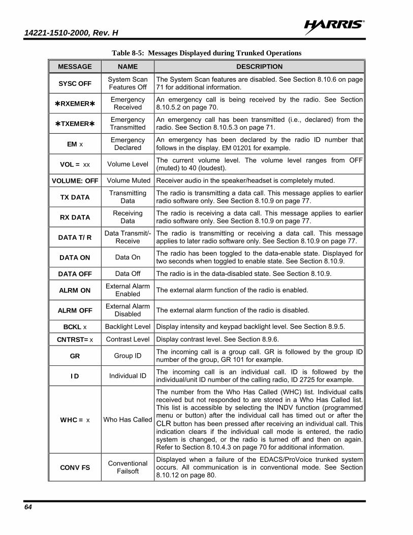
14221-1510-2000, Rev. H
64
Table 8-5: Messages Displayed during Trunked Operations
MESSAGE NAME DESCRIPTION
SYSC OFF System Scan Features Off
The System Scan features are disabled. See Section 8.10.6 on page 71 for additional information.
RXEMER Emergency Received
An emergency call is being received by the radio. See Section 8.10.5.2 on page 70.
TXEMER Emergency Transmitted
An emergency call has been transmitted (i.e., declared) from the radio. See Section 8.10.5.3 on page 71.
EM x Emergency Declared
An emergency has been declared by the radio ID number that follows in the display. EM 01201 for example.
VOL = xx Volume Level The current volume level. The volume level ranges from OFF (muted) to 40 (loudest).
VOLUME: OFF Volume Muted Receiver audio in the speaker/headset is completely muted.
TX DATA Transmitting Data
The radio is transmitting a data call. This message applies to earlier radio software only. See Section 8.10.9 on page 77.
RX DATA Receiving Data
The radio is receiving a data call. This message applies to earlier radio software only. See Section 8.10.9 on page 77.
DATA T/R Data Transmit/- Receive
The radio is transmitting or receiving a data call. This message applies to later radio software only. See Section 8.10.9 on page 77.
DATA ON Data On The radio has been toggled to the data-enable state. Displayed for two seconds when toggled to enable state. See Section 8.10.9.
DATA OFF Data Off The radio is in the data-disabled state. See Section 8.10.9.
ALRM ON External Alarm Enabled The external alarm function of the radio is enabled.
ALRM OFF External Alarm Disabled The external alarm function of the radio is disabled.
BCKL x Backlight Level Display intensity and keypad backlight level. See Section 8.9.5.
CNTRST=x Contrast Level Display contrast level. See Section 8.9.6.
GR Group ID The incoming call is a group call. GR is followed by the group ID number of the group, GR 101 for example.
ID Individual ID The incoming call is an individual call. ID is followed by the individual/unit ID number of the calling radio, ID 2725 for example.
WHC = x Who Has Called
The number from the Who Has Called (WHC) list. Individual calls received but not responded to are stored in a Who Has Called list. This list is accessible by selecting the INDV function (programmed menu or button) after the individual call has timed out or after the CLR button has been pressed after receiving an individual call. This indication clears if the individual call mode is entered, the radio system is changed, or the radio is turned off and then on again. Refer to Section 8.10.4.3 on page 70 for additional information.
CONV FS Conventional Failsoft
Displayed when a failure of the EDACS/ProVoice trunked system occurs. All communication is in conventional mode. See Section 8.10.12 on page 80.
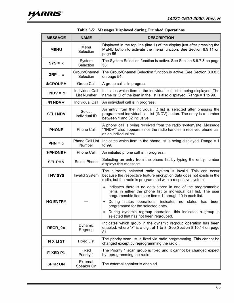
14221-1510-2000, Rev. H
65
Table 8-5: Messages Displayed during Trunked Operations
MESSAGE NAME DESCRIPTION
MENU Menu Selection
Displayed in the top line (line 1) of the display just after pressing the MENU button to activate the menu function. See Section 8.9.11 on page 55.
SYS = x System Selection
The System Selection function is active. See Section 8.9.7.3 on page 53.
GRP = x Group/Channel Selection
The Group/Channel Selection function is active. See Section 8.9.8.3 on page 54.
GROUP Group Call A group call is in progress.
INDV = x Individual Call List Number
Indicates which item in the individual call list is being displayed. The name or ID of the item in the list is also displayed. Range = 1 to 99.
INDV Individual Call An individual call is in progress.
SEL INDV Select Individual ID
An entry from the individual ID list is selected after pressing the programmed individual call list (INDV) button. The entry is a number between 1 and 32 inclusive.
PHONE Phone Call A phone call is being received from the radio system/site. Message “*INDV*” also appears since the radio handles a received phone call as an individual call.
PHN = x Phone Call List Number
Indicates which item in the phone list is being displayed. Range = 1 to 99.
PHONE Phone Call An initiated phone call is in progress.
SEL PHN Select Phone Selecting an entry from the phone list by typing the entry number displays this message.
INV SYS Invalid System The currently selected radio system is invalid. This can occur because the respective feature encryption data does not exists in the radio, but the radio is programmed with a respective system.
NO ENTRY —
• Indicates there is no data stored in one of the programmable items in either the phone list or individual call list. The user programmable items are items 1 through 10 in each list.
• During status operations, indicates no status has been programmed for the selected entry.
• During dynamic regroup operation, this indicates a group is selected that has not been regrouped.
REGR_0x Dynamic Regroup
Indicates which group in the dynamic regroup operation has been enabled, where “x” is a digit of 1 to 8. See Section 8.10.14 on page 81.
FIX LIST Fixed List The priority scan list is fixed via radio programming. This cannot be changed except by reprogramming the radio.
FIXED P1 Fixed Priority 1
The Priority 1 scan group is fixed and it cannot be changed expect by reprogramming the radio.
SPKR ON External Speaker On The external speaker is enabled.
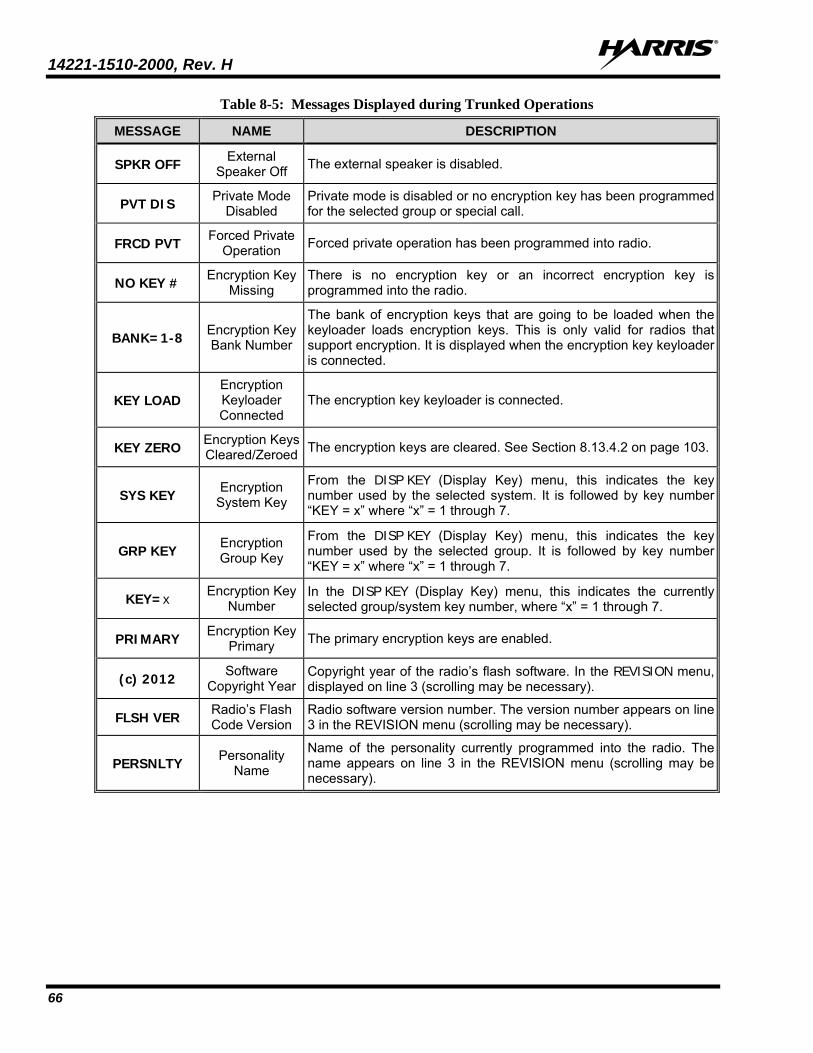
14221-1510-2000, Rev. H
66
Table 8-5: Messages Displayed during Trunked Operations
MESSAGE NAME DESCRIPTION
SPKR OFF External Speaker Off The external speaker is disabled.
PVT DIS Private Mode Disabled
Private mode is disabled or no encryption key has been programmed for the selected group or special call.
FRCD PVT Forced Private Operation Forced private operation has been programmed into radio.
NO KEY # Encryption Key Missing
There is no encryption key or an incorrect encryption key is programmed into the radio.
BANK=1-8 Encryption Key Bank Number
The bank of encryption keys that are going to be loaded when the keyloader loads encryption keys. This is only valid for radios that support encryption. It is displayed when the encryption key keyloader is connected.
KEY LOAD Encryption Keyloader Connected
The encryption key keyloader is connected.
KEY ZERO Encryption Keys Cleared/Zeroed The encryption keys are cleared. See Section 8.13.4.2 on page 103.
SYS KEY Encryption System Key
From the DISP KEY (Display Key) menu, this indicates the key number used by the selected system. It is followed by key number “KEY = x” where “x” = 1 through 7.
GRP KEY Encryption Group Key
From the DISP KEY (Display Key) menu, this indicates the key number used by the selected group. It is followed by key number “KEY = x” where “x” = 1 through 7.
KEY=x Encryption Key Number
In the DISP KEY (Display Key) menu, this indicates the currently selected group/system key number, where “x” = 1 through 7.
PRIMARY Encryption Key Primary The primary encryption keys are enabled.
(c) 2012 Software Copyright Year
Copyright year of the radio’s flash software. In the REVISION menu, displayed on line 3 (scrolling may be necessary).
FLSH VER Radio’s Flash Code Version
Radio software version number. The version number appears on line 3 in the REVISION menu (scrolling may be necessary).
PERSNLTY Personality Name
Name of the personality currently programmed into the radio. The name appears on line 3 in the REVISION menu (scrolling may be necessary).
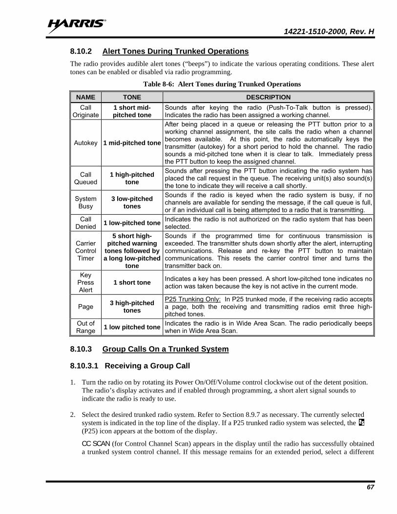
14221-1510-2000, Rev. H
67
8.10.2 Alert Tones During Trunked Operations The radio provides audible alert tones (“beeps”) to indicate the various operating conditions. These alert tones can be enabled or disabled via radio programming.
Table 8-6: Alert Tones during Trunked Operations
NAME TONE DESCRIPTION Call
Originate 1 short mid-pitched tone
Sounds after keying the radio (Push-To-Talk button is pressed). Indicates the radio has been assigned a working channel.
Autokey 1 mid-pitched tone
After being placed in a queue or releasing the PTT button prior to a working channel assignment, the site calls the radio when a channel becomes available. At this point, the radio automatically keys the transmitter (autokey) for a short period to hold the channel. The radio sounds a mid-pitched tone when it is clear to talk. Immediately press the PTT button to keep the assigned channel.
Call Queued
1 high-pitched tone
Sounds after pressing the PTT button indicating the radio system has placed the call request in the queue. The receiving unit(s) also sound(s) the tone to indicate they will receive a call shortly.
System Busy
3 low-pitched tones
Sounds if the radio is keyed when the radio system is busy, if no channels are available for sending the message, if the call queue is full, or if an individual call is being attempted to a radio that is transmitting.
Call Denied 1 low-pitched tone Indicates the radio is not authorized on the radio system that has been
selected.
Carrier Control Timer
5 short high-pitched warning
tones followed by a long low-pitched
tone
Sounds if the programmed time for continuous transmission is exceeded. The transmitter shuts down shortly after the alert, interrupting communications. Release and re-key the PTT button to maintain communications. This resets the carrier control timer and turns the transmitter back on.
Key Press Alert
1 short tone Indicates a key has been pressed. A short low-pitched tone indicates no action was taken because the key is not active in the current mode.
Page 3 high-pitched tones
P25 Trunking Only: In P25 trunked mode, if the receiving radio accepts a page, both the receiving and transmitting radios emit three high-pitched tones.
Out of Range 1 low pitched tone Indicates the radio is in Wide Area Scan. The radio periodically beeps
when in Wide Area Scan.
8.10.3 Group Calls On a Trunked System
8.10.3.1 Receiving a Group Call
1. Turn the radio on by rotating its Power On/Off/Volume control clockwise out of the detent position. The radio’s display activates and if enabled through programming, a short alert signal sounds to indicate the radio is ready to use.
2. Select the desired trunked radio system. Refer to Section 8.9.7 as necessary. The currently selected system is indicated in the top line of the display. If a P25 trunked radio system was selected, the (P25) icon appears at the bottom of the display.
CC SCAN (for Control Channel Scan) appears in the display until the radio has successfully obtained a trunked system control channel. If this message remains for an extended period, select a different
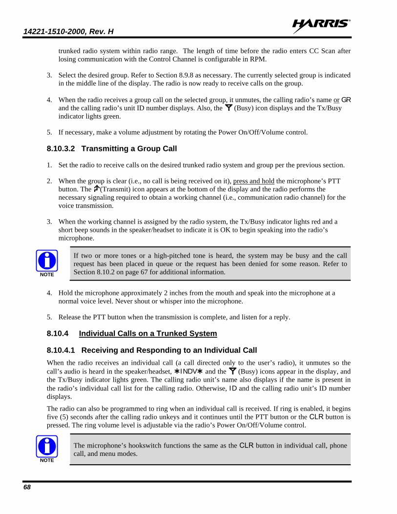
14221-1510-2000, Rev. H
68
trunked radio system within radio range. The length of time before the radio enters CC Scan after losing communication with the Control Channel is configurable in RPM.
3. Select the desired group. Refer to Section 8.9.8 as necessary. The currently selected group is indicated in the middle line of the display. The radio is now ready to receive calls on the group.
4. When the radio receives a group call on the selected group, it unmutes, the calling radio’s name or GR and the calling radio’s unit ID number displays. Also, the (Busy) icon displays and the Tx/Busy indicator lights green.
5. If necessary, make a volume adjustment by rotating the Power On/Off/Volume control.
8.10.3.2 Transmitting a Group Call
1. Set the radio to receive calls on the desired trunked radio system and group per the previous section.
2. When the group is clear (i.e., no call is being received on it), press and hold the microphone’s PTT button. The (Transmit) icon appears at the bottom of the display and the radio performs the necessary signaling required to obtain a working channel (i.e., communication radio channel) for the voice transmission.
3. When the working channel is assigned by the radio system, the Tx/Busy indicator lights red and a short beep sounds in the speaker/headset to indicate it is OK to begin speaking into the radio’s microphone.
If two or more tones or a high-pitched tone is heard, the system may be busy and the call request has been placed in queue or the request has been denied for some reason. Refer to Section 8.10.2 on page 67 for additional information.
4. Hold the microphone approximately 2 inches from the mouth and speak into the microphone at a normal voice level. Never shout or whisper into the microphone.
5. Release the PTT button when the transmission is complete, and listen for a reply.
8.10.4 Individual Calls on a Trunked System
8.10.4.1 Receiving and Responding to an Individual Call When the radio receives an individual call (a call directed only to the user’s radio), it unmutes so the call’s audio is heard in the speaker/headset, INDV and the (Busy) icons appear in the display, and the Tx/Busy indicator lights green. The calling radio unit’s name also displays if the name is present in the radio’s individual call list for the calling radio. Otherwise, ID and the calling radio unit’s ID number displays.
The radio can also be programmed to ring when an individual call is received. If ring is enabled, it begins five (5) seconds after the calling radio unkeys and it continues until the PTT button or the CLR button is pressed. The ring volume level is adjustable via the radio’s Power On/Off/Volume control.
The microphone’s hookswitch functions the same as the CLR button in individual call, phone call, and menu modes.
NOTE
NOTE
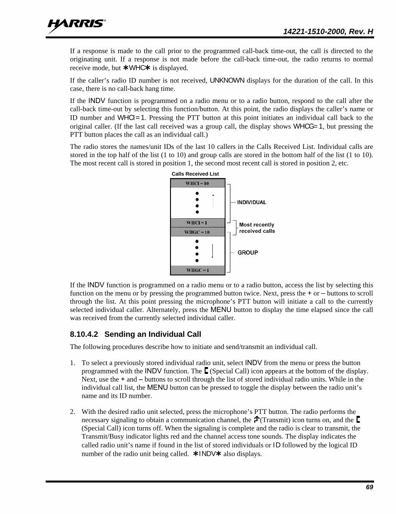
14221-1510-2000, Rev. H
69
If a response is made to the call prior to the programmed call-back time-out, the call is directed to the originating unit. If a response is not made before the call-back time-out, the radio returns to normal receive mode, but WHC is displayed.
If the caller’s radio ID number is not received, UNKNOWN displays for the duration of the call. In this case, there is no call-back hang time.
If the INDV function is programmed on a radio menu or to a radio button, respond to the call after the call-back time-out by selecting this function/button. At this point, the radio displays the caller’s name or ID number and WHCI=1. Pressing the PTT button at this point initiates an individual call back to the original caller. (If the last call received was a group call, the display shows WHCG=1, but pressing the PTT button places the call as an individual call.)
The radio stores the names/unit IDs of the last 10 callers in the Calls Received List. Individual calls are stored in the top half of the list (1 to 10) and group calls are stored in the bottom half of the list (1 to 10). The most recent call is stored in position 1, the second most recent call is stored in position 2, etc. Calls Received List
If the INDV function is programmed on a radio menu or to a radio button, access the list by selecting this function on the menu or by pressing the programmed button twice. Next, press the + or – buttons to scroll through the list. At this point pressing the microphone’s PTT button will initiate a call to the currently selected individual caller. Alternately, press the MENU button to display the time elapsed since the call was received from the currently selected individual caller.
8.10.4.2 Sending an Individual Call The following procedures describe how to initiate and send/transmit an individual call.
1. To select a previously stored individual radio unit, select INDV from the menu or press the button programmed with the INDV function. The (Special Call) icon appears at the bottom of the display. Next, use the + and – buttons to scroll through the list of stored individual radio units. While in the individual call list, the MENU button can be pressed to toggle the display between the radio unit’s name and its ID number.
2. With the desired radio unit selected, press the microphone’s PTT button. The radio performs the necessary signaling to obtain a communication channel, the (Transmit) icon turns on, and the (Special Call) icon turns off. When the signaling is complete and the radio is clear to transmit, the Transmit/Busy indicator lights red and the channel access tone sounds. The display indicates the called radio unit’s name if found in the list of stored individuals or ID followed by the logical ID number of the radio unit being called. INDV also displays.
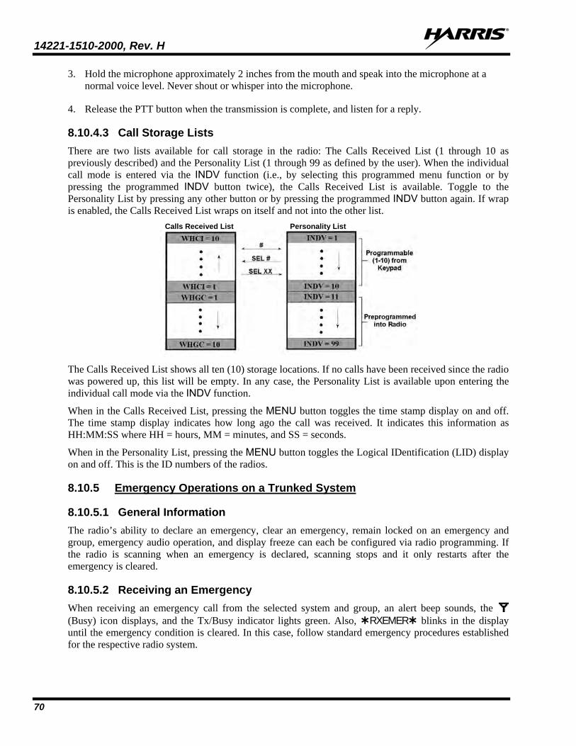
14221-1510-2000, Rev. H
70
3. Hold the microphone approximately 2 inches from the mouth and speak into the microphone at a normal voice level. Never shout or whisper into the microphone.
4. Release the PTT button when the transmission is complete, and listen for a reply.
8.10.4.3 Call Storage Lists There are two lists available for call storage in the radio: The Calls Received List (1 through 10 as previously described) and the Personality List (1 through 99 as defined by the user). When the individual call mode is entered via the INDV function (i.e., by selecting this programmed menu function or by pressing the programmed INDV button twice), the Calls Received List is available. Toggle to the Personality List by pressing any other button or by pressing the programmed INDV button again. If wrap is enabled, the Calls Received List wraps on itself and not into the other list. Calls Received List Personality List
The Calls Received List shows all ten (10) storage locations. If no calls have been received since the radio was powered up, this list will be empty. In any case, the Personality List is available upon entering the individual call mode via the INDV function.
When in the Calls Received List, pressing the MENU button toggles the time stamp display on and off. The time stamp display indicates how long ago the call was received. It indicates this information as HH:MM:SS where HH = hours, MM = minutes, and SS = seconds.
When in the Personality List, pressing the MENU button toggles the Logical IDentification (LID) display on and off. This is the ID numbers of the radios.
8.10.5 Emergency Operations on a Trunked System
8.10.5.1 General Information The radio’s ability to declare an emergency, clear an emergency, remain locked on an emergency and group, emergency audio operation, and display freeze can each be configured via radio programming. If the radio is scanning when an emergency is declared, scanning stops and it only restarts after the emergency is cleared.
8.10.5.2 Receiving an Emergency When receiving an emergency call from the selected system and group, an alert beep sounds, the (Busy) icon displays, and the Tx/Busy indicator lights green. Also, RXEMER blinks in the display until the emergency condition is cleared. In this case, follow standard emergency procedures established for the respective radio system.
14221-1510-2000, Rev. H
71
8.10.5.3 Declaring an Emergency To declare (send/transmit) an emergency call to the selected system and group or to an optionally programmed emergency group, follow this procedure. It is assumed the Home/Emergency button is programmed to provide an emergency declaration function, and the radio is programmed with the emergency declaration capability:
1. Set the radio to receive calls on the desired trunked radio system. Refer to Section 8.10.3.1 on page 67 as necessary.
2. If the radio is programmed to transmit an emergency on the selected group, select the desired group to transmit the emergency on. Refer to Section 8.9.8 on page 53 as necessary.
3. Press and hold the red Home/Emergency button. The required minimum button hold time is programmable between 0 and 127 seconds; consult with the radio system’s network administration personnel for the specific hold time. Afterwards, the radio transmits an emergency call request with the radio’s ID number until an emergency working channel assignment is received.
4. When the emergency working channel assignment is received, the radio sounds a single beep (auto-key alert tone) indicating it is ready for voice transmission. TXEMER blinks in the display until the emergency is cleared.
5. Press PTT and speak into the microphone in a normal voice. When the radio is transmitting, the (Transmit) icon appears at the bottom of the display and the Tx/Busy indicator lights red.
6. Release PTT when the transmission is complete and listen for a reply.
8.10.5.4 Clearing an Emergency If the radio is programmed with emergency clear capability, an emergency can be cleared as follows: Press and hold the CLR button, then press the red Home/Emergency button, then finally release both buttons.
8.10.6 System Scan Operations on a Trunked System
8.10.6.1 General Information The radio can be programmed with several different radio system scan related features as described in the following subsections. These features are automatically enabled upon radio power up. A button or menu option may also be defined to allow these features, as programmed, to be toggled on and off. The system scan state is maintained through system changes performed by the radio operator, but it defaults to the on state at radio power-up.
8.10.6.2 Wide Area System Scan The radio can be programmed for Wide Area System Scan operation for roaming across trunked radio systems. Trunked radio systems manage the radios assigned to the system via control channels throughout the radio systems. Upon the loss of the currently selected system’s control channel, the radio can be programmed to automatically scan the control channels of other systems. During this scan condition, WA SCAN displays. If a new control channel is found, the radio switches to the new system and sounds an alert tone. The amount of time before the radio enters Control Channel Scan after losing the control channel is configurable in RPM.
14221-1510-2000, Rev. H
72
If the radio cannot find the control channel of the selected system and begins Wide Area System Scan (WA Scan), the radio only scans for the priority system control channel if the priority system is in the WA Scan list.
8.10.6.3 ProScan The radio can be programmed for ProScan system scan operation for multi-site applications. When the currently selected system’s signal quality drops below a predefined level, ProScan provides the radio with the ability to select a new system for the radio to communicate on. This is accomplished by enabling each radio to analyze the signal quality of its current control channel and compare it with the signal quality of the control channel for each site in its adjacency scan list. The signal quality metric used for the ProScan algorithm is based on a combination of both Received Signal Strength Indicator (RSSI) and Control Channel Verification (CCV) measurements. When the selected system’s signal quality level degrades below a programmed level, the radio begins to look for a better control channel. Once a control channel that exceeds the programmed parameters is found, the radio changes to the new system and emits a tone. If the control channel is completely lost, the radio enters Wide Area System Scanning and searches the programmed adjacent systems until a suitable control channel is found.
The radio monitors the priority system and switches to the priority system if the priority system meets the criteria. If ProScan is enabled, the rate at which the radio scans for the priority system is defined by the System Sample Time control.
8.10.6.4 Priority System Scan The radio can also be programmed for Priority System Scan. To ensure this feature operates correctly, the control channel of the priority system must be located on channel one unless the ProScan algorithm is being used.
The priority system is the desired or preferred system. While receiving the control channel of the selected system, the radio periodically leaves the selected system and searches for the control channel of the priority system at a programmable rate. The programmable rate is defined by the value in the Priority Scan Time control, unless the ProScan algorithm is enabled. This priority scan timer is reset each time the PTT button is pressed or when a call is received. If the priority system control channel is found, or meets the predefined ProScan criteria, the radio automatically switches to the priority system.
8.10.6.5 Turning System Scan On and Off
8.10.6.5.1 With the Menu (if Programmed) If the System Scan function is programmed to a radio menu, press the MENU button and then press the + or – buttons to scroll through the menu until SYS SCAN displays. Next, press the MENU button again to toggle the System Scan state between on and off. SYSC ON or SYSC OFF displays for two seconds to show the new system scan state.
8.10.6.5.2 With a Button (if Programmed) If the System Scan function is programmed to a radio button, press this button to toggle the system scan feature on and off. SYSC ON or SYSC OFF displays for two seconds to show the new system scan state.
8.10.7 Group Scan Operations on a Trunked System
8.10.7.1 General Information Talk groups on the radio’s scan list are scanned when the scan feature is turned on (i.e., enabled). Groups are added to the scan list on a per system basis through programming, the radio keypad, or both,
14221-1510-2000, Rev. H
73
dependent upon programming. The scan list can be changed by the user from the keypad if the radio is not programmed with a fixed list. Each system’s group scan list is retained in memory when the radio is turned off. The radio can also be programmed to provide Trunked Priority Group Scan capability, which operates similar to priority scan in analog conventional mode. Group scan related features include:
• Scan Hang Time — The delay time the radio waits before resuming scan after the microphone’s push-to-talk button is released or after the received call has ended (i.e., after the working channel has dropped).
• TX Select — The group the radio transmits on while scanning. The radio is programmed to transmit on either the scanned group or the selected group.
• Scan List (privileges) — This feature allows or prohibits scan list changes by the user.
• P1 Programming — Priority group programming is accomplished by one (and only one) of the following three methods: From the keypad, where the priority programming is not fixed and does not follow the selected
channel; Priority 1 group programming follows the selected channel; or, Priority 1 group programming is fixed during PC programming and cannot be changed by the
user.
• P1 Always Scan — Determines if the Priority 1 group is always scanned, regardless of the scan state set by the user.
8.10.7.2 Turning Scan On and Off Toggle scan operation between on (enabled) and off (disabled) by pressing the button programmed with the SCAN function (typically the SCAN button) or, if programmed, by selecting this function on the menu. When scan is scanning groups, (i.e., when scan is on/enabled), the (Scan) icon rotates in the bottom of the display and the radio scans the groups on the trunked group scan list.
Scanning stops when the radio is receiving or transmitting a call. Scanning also stops while the microphone is off-hook, if the hookswitch feature is enabled through programming.
If the radio is not programmed to scan, SCAN DIS (for scan disabled) displays when the SCAN function is selected.
When a group on the scan list receives a channel assignment, the radio unmutes on the assigned channel, the Transmit/Busy indicator lights green and the received scan group is displayed.
The radio continues scanning if a new group is selected when scan is on. If the radio is receiving a call on a non-selected group when scan is turned off, it returns to the selected group.
Pressing the microphone’s PTT button when scan is on causes the radio to transmit either on the displayed group or on the currently selected group, depending on programming.
When the radio is scanning, selecting the SCAN ADD function (if programmed) recalls the scanned group that last received a call. This group is recalled for a period equal to the scan hang-time.
NOTE
NOTE
14221-1510-2000, Rev. H
74
8.10.7.3 Priority Group Scanning When scan is on (enabled) and the scan list has Priority 1 and Priority 2 groups, the radio listens to calls on those groups and the selected group. While receiving a scanned group call, the radio continues to monitor the selected Priority 1 and Priority 2 groups and drops the call if the selected group or other higher priority call becomes active. During a Priority 2 call the radio continues to monitor for a Priority 1 group call.
The radio monitors for Agency and Fleet calls that correspond to the Agency and Fleet associated with the Priority 1 and Priority 2 groups. Priority Agency and Fleet calls are indicated by displaying AGENCY or FLEET and associated Priority 1 or 2 group.
8.10.7.4 Adding Groups to the Scan List and Changing a Group’s Scan Priority Either the SCAN ADD function or the SCAN A/D (add/delete) function can be used to add a group to the scan list and change its scan priority level. This procedure assumes the desired group for adding to the scan list is programmed in the currently selected system but not currently on the scan list. Also, it is assumed the radio is not programmed with a fixed scan list.
1. Turn scan off, if it is not already off. This can be accomplished by pressing the button programmed with the SCAN function (typically the SCAN button) or, if programmed, by selecting this function on the menu. When scan is off, the icon is not displayed.
2. Select the SCAN ADD function or the SCAN A/D function to add the currently selected group to the scan list as a non-priority scan group. Either function may be programmed to a radio button or on the menu. When set as a non-priority scan group, the icon (non-priority scan icon = 3 bars) appears at the bottom of the display.
If neither function is programmed, it is not possible to add the group to the scan list unless the radio is re-programmed.
If the radio displays FIXED LST, it is programmed with a fixed scan list and this list cannot be changed without radio re-programming.
3. If desired, select the same function again to set the group as the Priority 2 scan group. The icon (Priority 2 scan icon = 2 bars) appears at the bottom of the display.
4. If desired, select the same function again to set the group as the Priority 1 scan group. The icon (Priority 1 scan icon = 1 bar) appears at the bottom of the display.
If the radio displays FIXED P1, a group has been programmed as the fixed Priority 1 group. In this case, another group cannot be set as the Priority 1 group, and the fixed Priority 1 group cannot be changed from the Priority 1 group unless the radio is re-programmed.
5. Another group can be added to the list by selecting the group and then repeating from step 2.
6. If desired, turn scan on by selecting the SCAN function.
If the Priority 1 and Priority 2 groups were already set and a new group is assigned as the Priority 1 or the Priority 2 scan group, then the previously assigned group changes to non-priority scanning.
NOTE
NOTE
14221-1510-2000, Rev. H
75
When using the SCAN ADD function, the priority level selection sequence advances the group to the next higher priority level and stops at Priority 1. To select a lower priority level, the group must be deleted from the scan list (using the SCAN DEL function or the SCAN A/D function) and then added back to the scan list. Each new group added to the scan list starts at the non-priority level (i.e., the lowest level).
When using the SCAN A/D function, the priority level selection sequence wraps from Priority 1 to no scan. Since this function can both add and delete, it may be desired so other functions can be programmed to the limited number of radio buttons.
8.10.7.5 Deleting Groups from the Scan List Either the SCAN DEL (scan delete) function or the SCAN A/D (scan add/delete) function can be used to delete a group from the scan list. The SCAN A/D function can also be used to change the group’s scan priority level. This procedure assumes the desired group for deleting from the scan list is programmed in the currently selected system and currently on the scan list. Also, it is assumed the radio is not programmed with a fixed scan list.
1. Turn scan off, if it is not already off. This can be accomplished by pressing the button programmed with the SCAN function (typically the SCAN button) or, if programmed, by selecting this function on the menu. When scan is off, the icon is not displayed.
2. If programmed, select the SCAN DEL function once to delete/remove the group from the scan list. The scan icon clears from the display when this function is selected.
Alternately, select the SCAN A/D function one or more times until no scan icons (i.e., no bars) appear in the display. At this point, the group is removed from the scan list.
If neither function is programmed, it is not possible to delete the group from the scan list unless the radio is re-programmed.
3. If desired, turn scan on by selecting the SCAN function.
8.10.7.6 Nuisance Delete If not the currently selected group, a group can be temporarily deleted from the scan list by selecting the SCAN DEL (scan delete) function when the radio is scanning and receiving a call on the unwanted group. This action prevents calls from being received on the unselected group, since the group is temporarily removed from the scan list. Deletions performed in this manner do not remain deleted after the radio is turned off and back on.
8.10.8 Telephone Interconnect Call Operations on a Trunked System
8.10.8.1 Receiving a Telephone Interconnect Call When the radio receives a telephone interconnect call, it unmutes on the assigned working channel, and displays PHONE, INDV and the (Busy) icon. A telephone interconnect call is handled similar to an individual call in the trunked system; it is only directed to an individual radio in the system.
To respond to the caller and proceed with the call, press the microphone’s PTT button and speak into the mic at a normal voice level. When done speaking, release the PTT button and listen for a reply. Repeat as necessary to complete the conversation.
14221-1510-2000, Rev. H
76
See the DTMF Overdial section that follows if access to services requiring “overdial” is needed. Overdial operations are available for any special call whether it is an individual call or a telephone interconnect call.
8.10.8.2 Sending a Telephone Interconnect Call Use the following procedure to initiate and complete a telephone interconnect call:
1. To select the desired programmed telephone number, select the PHONE function (programmed menu or button) then use the + or – buttons to scroll through the list until the desired number is displayed.
2. Press and release the PTT button. The radio performs the necessary signaling required to obtain a communication channel for the call. When the signaling is complete and the radio is clear to transmit, its Transmit/Busy indicator lights red and the channel access tone sounds. The display shows *PHONE* and indicates the accompanying name. The radio then automatically transmits the number.
Unsuccessful interconnect signaling returns the radio to the normal receive mode and the number remains displayed until the special call is cleared by pressing the CLR button or the time-out expires or another group or system is selected.
3. Telephone ringing is heard. When someone answers the phone, press the microphone’s PTT button and speak into the mic at a normal voice level. Release the PTT button to listen to the caller.
4. To terminate the call, momentarily press the CLR button.
The radio is only capable of half-duplex conversations. The caller’s message can only be sent if the PTT button is pressed (the radio is transmitting) and the caller can only be heard when the PTT is released (the radio is receiving).
8.10.8.3 DTMF Overdial of Programmed Numbers Once the radio has established a connection to the public telephone system, it may be necessary to “overdial” more digits to access banking services, answering machines, credit card calls or other types of systems that require DTMF (Dual-Tone Multi-Frequency) access digits. Overdial operation can also be used to initiate a telephone interconnect call via DTMF signaling if a dial tone has already been accessed on the system. Telephone numbers and other number sequences needed during overdial operations can be programmed into the radio’s phone list.
1. Follow the Sending a Telephone Interconnect Call procedure to establish a connection to the telephone system, or consult the radio system administrator for the procedure necessary to access a dial tone on the trunked radio system.
2. To select the desired programmed number, select the PHONE function (programmed menu or button) then use the + or – buttons to scroll through the list and select the desired number.
3. Press the microphone’s PTT button to send/transmit the selected number.
If a number needs to be transmitted again during the call, it must be selected again via the PHONE function and the PTT button must be pressed again. This requirement prevents unwanted numbers from being transmitted the next time(s) the PTT button is pressed during the call.
NOTE
14221-1510-2000, Rev. H
77
The overdial selection mode remains active until the call is dropped, cleared, or the radio’s MENU button is pressed. The overdial selection mode can be re-entered if the call is still active by pressing the MENU button.
8.10.9 Mobile Data on a Trunked System
8.10.9.1 General Information During trunked mode operations, voice or data calls can be transmitted or received by the radio. However, the radio can handle only one type of call at a time. Selection of either data or voice is selected transparently by the operator through normal usage of the radio.
The radio can be connected to a Mobile Data Terminal (MDT) or to a host computer. Any RS-232 compatible device that supports the Radio Data Interface (RDI) protocol (Version 1.91 or greater) can be connected to the radio. Support for a MDT or host computer is a programmable option. Additionally, a radio programmed for a host computer can also be programmed for data-only operation (i.e., no voice calls can be transmitted or received).
Always turn the radio off before connecting or disconnecting any cables, including the data cable. Also, turn power to the radio off when docking or undocking a connected laptop computer. Failure to turn the power off can damage the radio, requiring service by a Harris approved service center.
8.10.9.2 Mobile Data-Related Messages The following messages may be displayed during the various states of data mode of operation:
TX DATA — Displayed when the radio is transmitting a data call (earlier radio software only).
RX DATA — Displayed when the radio is receiving a data call (earlier radio software only).
DATA T/R — Displayed when the radio is transmitting or receiving a data call (later radio software only).
DATA OFF — Displayed when the radio is in the data disabled state.
DATA ON — Displayed for two seconds when the radio is toggled to the data enabled state.
8.10.9.3 Mobile Data Off Operation The radio can be placed in the data disabled state by any of the following methods. When the data state is disabled, the DATA OFF displays. An ongoing data call is allowed to complete except when an emergency is declared.
• Removing the microphone from the hookswitch (hookswitch option must be enabled by programming).
• Declaring an emergency (not to be used unless an actual emergency condition exists). Alert tone sounds.
• Pressing the OPT button. Alert tone sounds.
• Selecting the programmed function via the MENU button.
14221-1510-2000, Rev. H
78
8.10.9.4 Mobile Data On Operation The data state is enabled by one of the following (depending on how it was disabled). DATA ON displays for two (2) seconds then the display returns to normal.
• Replacing the microphone into the hookswitch (going on-hook). Only valid if the DATA OFF operation was entered by removing the microphone from the hookswitch (going off-hook).
• Clearing an emergency, but valid only if an emergency caused DATA OFF operation.
8.10.9.5 Exiting Mobile Data Calls Under normal conditions, the radio enters the scan lockout mode and returns to the control channel after completion of a data call (transmit or receive). If, during a data call, one of the following conditions occurs, the data call is immediately terminated and the radio performs the desired function:
• The PTT is activated.
• An emergency is declared by pressing the programmed Emergency/Home button.
• A group or system change is made.
8.10.9.6 Scan Lockout Mode Following the transmission or reception of a data call, if scan is enabled, scanning stops temporarily (duration programmed). During this time the scan status icon stops rotating to indicate that scan is enabled but temporarily suspended. This mode is normally exited when the programmed time expires; however, the following actions terminate the scan lockout mode before the timeout is completed.
• Pressing the CLR button.
• Pressing the microphone’s PTT button.
• Removing the microphone from its hookswitch (i.e., going “off-hook”).
• Changing the currently selected group or system.
• Entering phone call mode.
• Entering individual call mode.
• Receiving a new emergency assignment.
• Declaring or clearing an emergency.
• Receiving an individual or phone call.
• Receiving an Agency, Fleet, or System All Call.
• Pressing the SCAN button (or selecting the SCAN function) to turn scan on or off.
8.10.9.7 Data Lockout Mode The data lockout mode is a programmed mode. When enabled, the radio does not respond to any data channel assignments and prevents receive data calls from interrupting voice calls. Transmit data calls are still initiated when needed by the operator. After a programmed time, the radio responds to receive data calls; however, the following conditions clear the data lockout mode:
• Pressing the CLR button.
• Transmitting a data call.
14221-1510-2000, Rev. H
79
• Changing the system.
• Declaring an emergency.
• Pressing the SCAN button (or selecting the SCAN function) to turn scan on or off.
8.10.10 Status Operations on a Trunked System The Status feature allows for the transmission of programmed statuses to the radio system. Different statuses can be programmed into the radio and selected one-at-a-time for transmission. Each status is assigned an ID number that is cross-referenced with the representative status condition established by radio system administration personnel. For example, a particular status ID number could be assign as meaning “Off Duty” throughout the radio system. Note that the same ID number could be programmed, for example, as “STATUS 1” in one radio but as “STATUS 5” in another radio. At dispatch consoles in the radio system, the Status feature is typically referred to as Request Status Message (RSM).
One or more radio buttons may be programmed for status operation. For examples, the A button could be programmed to transmit an “En Route” status after it is pressed, the B button could be programmed to transmit an “At Scene” status after it is pressed, and the C button could be programmed to transmit a “Send EMT” status after it is pressed.
To transmit a status, press the respective button to set the status for transmission. After a short delay or after being polled by the radio system (per radio programming), the status will be transmitted. Consult with radio system’s network administration personnel for programming information for a specific radio.
Transmission of the status set for transmission can be canceled before the timer expires (or before the radio system polls the radio for it, if so programmed) by pressing the CLR button. This may be necessary if an incorrect status was selected.
If the radio is programmed for automatic status transmission, it transmits the selected status each time the status is set for transmission (and if used, after the timer expires). However, if the radio is programmed for polled status transmission, the radio waits until it is polled by the radio system (i.e., the trunked site) before it transmits the selected status set for transmission.
If the status cannot be transmitted immediately, it is stored in the radio’s memory where it can be polled by the radio system at a future time.
When the radio system receives a transmitted status, it sends an acknowledgement message back to the radio and the radio then sounds a high-pitched tone. If the radio system does not receive the status properly, the radio sounds a low-pitched tone upon receipt of the acknowledgement message from the radio system.
If no status has been programmed for the selected status, the NO ENTRY displays and the radio sounds a low-pitched tone.
8.10.11 Message Operations on a Trunked System The Message feature allows for the transmission of programmed messages to the radio system. Different messages can be programmed into the radio and selected one-at-a-time for transmission. Each message is assigned an ID number that is cross-referenced with the representative message condition established by radio system administration personnel. For example, a particular message ID number could be assign as meaning “Please Call” throughout the radio system. Note that the same ID number could be programmed, for example, as “MESSAGE 1” in one radio but as “MESSAGE 5” in another radio. At dispatch consoles in the radio system, the Message feature is typically referred to as Request-To-Talk (RTT), since it allows a dispatcher to quickly set-up an individual call back to the radio that transmitted a message.
NOTE
14221-1510-2000, Rev. H
80
One or more radio buttons may be programmed for message operation. For examples, the A button could be programmed to transmit a message corresponding to “I-Call ASAP” after it is pressed, and the B button could be programmed to transmit a message corresponding to “Run Plate” after it is pressed.
To transmit a message, press the respective button to set the message for transmission. After a short delay or after being polled by the radio system (per radio programming), the message will be transmitted. Consult with radio system’s network administration personnel for programming information for a specific radio.
Transmission of the message set for transmission can be canceled before the timer expires (or before the radio system polls the radio for it, if so programmed) by pressing the CLR button. This may be necessary if an incorrect message was selected.
If the radio is programmed for automatic message transmission, it transmits the selected message each time the message is set for transmission (and if used, after the timer expires). However, if the radio is programmed for polled message transmission, the radio waits until it is polled by the radio system (i.e., the trunked site) before it transmits the selected message set for transmission.
If the message cannot be transmitted immediately, it is stored in the radio’s memory where it can be polled by the radio system at a future time.
When the radio system receives a transmitted message, it sends an acknowledgement message back to the radio and the radio then sounds a high-pitched tone. If the radio system does not receive the message properly, the radio sounds a low-pitched tone upon receipt of the acknowledgement message from the radio system.
If no message has been programmed for the selected message, the NO ENTRY displays and the radio sounds a low-pitched tone.
8.10.12 Conventional Failsoft (EDACS/ProVoice Only) In the unlikely event of an EDACS/ProVoice trunked radio system failure, communications can take place in a system mode know as “conventional failsoft” mode. In this mode, the radio is automatically directed to a communications channel set up for this purpose, and the radio displays a CONV FS message. An increase in activity on the channel during conventional failsoft operation may be noticed. In this case, do not to transmit until the channel is clear.
Operation during conventional failsoft is the same as operation on a conventional system, except that it is not possible to select a communications channel, or use emergency and special call. When trunking is restored, the radio is automatically returned to normal operation.
Trunked Emergency and Special Call do not function when the conventional failsoft mode is active. In addition, the group control (GRP) does not operate.
8.10.13 Conventional Priority The Conventional Priority Scan feature (sometimes referred to as “ECP1 Scan”) allows the radio, when operating on a trunked radio system, to scan a programmed conventional system and channel as a priority channel. If activity is detected on this channel, the radio unmutes and remains on this channel for the programmable hang-time. This feature is available for EDACS, ProVoice and P25 trunked radio systems/modes. It must be programmed to the radio’s trunked menu or to a radio button to allow it to be turned on and off. At radio power-up, it is always off (disabled).
NOTE
NOTE
14221-1510-2000, Rev. H
81
8.10.14 Dynamic Regroup Operation
8.10.14.1 General Information Dynamic regroup operation is a feature that permits up to eight (8) talk groups to be added to a radio by network administration personnel. The radio must be programmed to respond to regrouping. Dynamic regrouping is not activated in a radio until an activation message is sent from the radio system. Each radio that receives and acknowledges regrouping instructions is successfully regrouped.
Pressing and holding the CLR button for 2.5 seconds toggles the radio into and out of the dynamic regroup group set. A double beep sounds for entry or exit. The radio displays REGR_0x where x is a digit of 1 to 8 indicating the group when dynamic regroup has been enabled by the user. If the radio is in dynamic regroup and the user selects a group that has not been regrouped, NO ENTRY displays. The radio is prevented from transmitting and receiving calls in this condition except for scanned groups.
8.10.14.2 Emergency Operation If the programmed group set on the currently selected system contains an emergency/home group and the radio is in dynamic regroup, the radio exits dynamic regroup and declares the emergency on the home group. If no emergency/home group is present, the radio declares the emergency on the currently selected dynamic regroup group.
8.10.15 Paging Operations (P25 Trunked Systems Only) The radio’s paging feature, if programmed, sends a “ping” type message to another radio in a P25 trunked system. It functions similar to the individual call feature. To initiate and complete a page:
1. Press the MENU button to activate the menu function. The programmed menu functions appear in the display. The > symbol at the left of a menu function indicates the currently selected function.
Alternately, if another button such as one (1) of the three (3) preset buttons is programmed with the Page function, press this button and advance to step 4.
2. Press the + or – buttons to scroll through the menu until PAGE is selected with the > symbol.
3. Press the MENU button again to access the individual call list.
4. Press the + or – buttons to select a previously stored radio via the individual call list. While in the individual call list, press the MENU button to toggle the display between the calling radio’s call name (i.e., alias) and the calling radio’s unit ID number (i.e., logical ID number).
5. Press the microphone’s PTT button. The radio performs the necessary signaling on the control channel. On the calling radio, the called individual’s name if found in the individuals call list, or ID followed by the radio unit ID number of the radio being called displays. If the receiving radio receives the page and responds, both radios emit three (3) high-pitched tones. The receiving radio also displays PAGE and the calling radio’s identification.
14221-1510-2000, Rev. H
82
8.11 P25 CONVENTIONAL OPERATIONS The following subsections describe operations when a P25 conventional radio system is selected.
8.11.1 Messages Displayed During P25 Conventional Operations During P25 conventional operations, various messages may appear in the display, as listed and described in the following table:
Table 8-7: Messages Displayed during P25 Conventional Operations
MESSAGE NAME DESCRIPTION
TALKARND Talk-Around
The radio is operating in talk-around mode. In this mode, the radio’s transmit and receive frequencies are the same for the currently selected channel. Appears in the top line of the display when the radio is in this mode; otherwise, the selected system’s name appears there.
SYS ALL System All Call A system all-call has been received.
REGISTER Registration Displayed when the radio is performing a registration/affiliation. See footnote 1.
RXEMER Emergency Received
An emergency call is being received by the radio. See Section 8.11.5.1 on page 87.
TXEMER Emergency Transmitted
An emergency call has been transmitted (i.e., declared) from the radio. See Section 8.11.5.2 on page 87.
EM x Emergency Declared
An emergency has been declared by the radio ID number that follows in the display. EM 01201 for example.
UNKNOWN Caller's ID Not Received
An individual call is being received, but the caller's ID was not received. See Section 8.11.4.1 on page 86.
VOL = xx Volume Level The current volume level. The volume level ranges from OFF (muted) to 40 (loudest).
VOLUME: OFF Volume Muted Receiver audio in the speaker/headset is completely muted.
TX DATA Transmitting Data
The radio is transmitting a data call. This message applies to earlier radio software only.
RX DATA Receiving Data
The radio is receiving a data call. This message applies to earlier radio software only.
DATA T/R Data Transmit/- Receive
The radio is transmitting or receiving a data call. This message applies to later radio software only.
DATA ON Data On The radio has been toggled to the data-enable state. Displayed for two seconds when toggled to enable state.
DATA OFF Data Off The radio is in the data-disabled state.
ALRM ON External Alarm Enabled The external alarm function of the radio is enabled.
ALRM OFF External Alarm Disabled The external alarm function of the radio is disabled.
1 Registration on a P25 conventional system was not supported prior to XGP Release R2, or in any release of ECP.
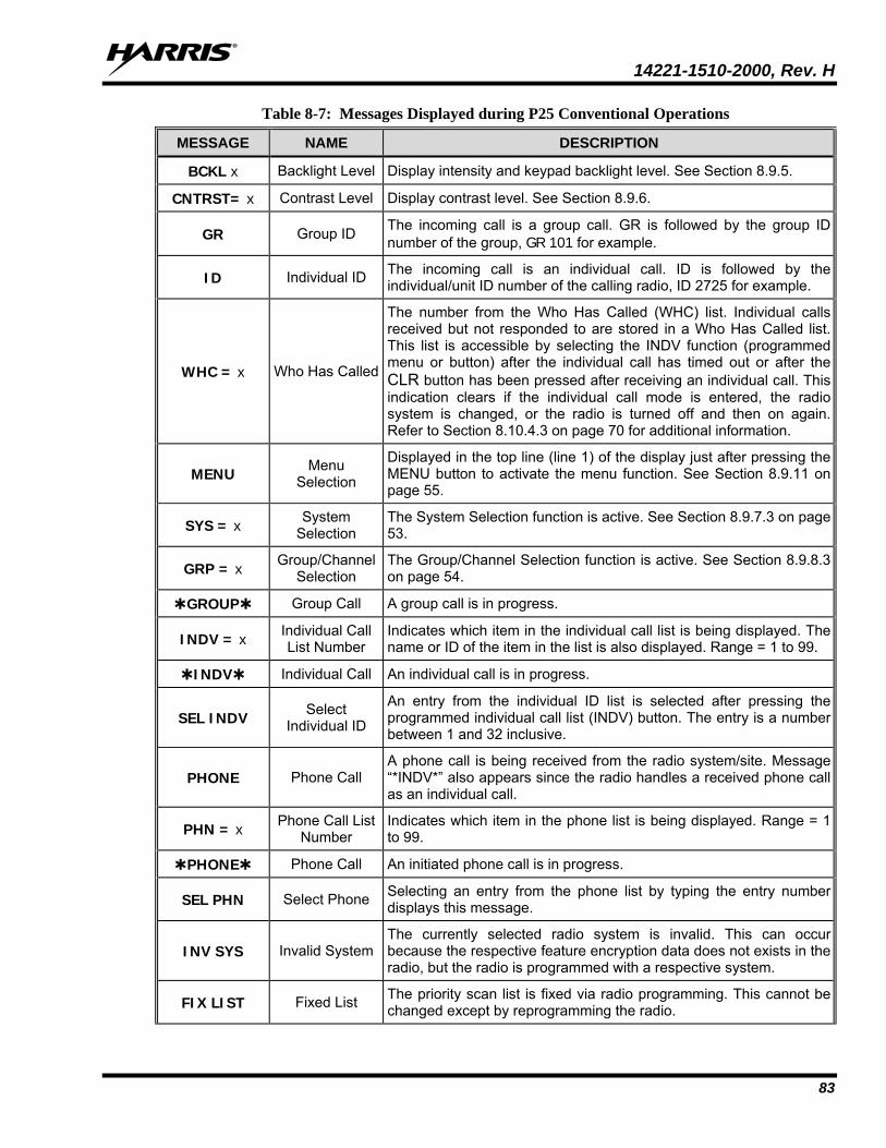
14221-1510-2000, Rev. H
83
Table 8-7: Messages Displayed during P25 Conventional Operations
MESSAGE NAME DESCRIPTION
BCKL x Backlight Level Display intensity and keypad backlight level. See Section 8.9.5.
CNTRST= x Contrast Level Display contrast level. See Section 8.9.6.
GR Group ID The incoming call is a group call. GR is followed by the group ID number of the group, GR 101 for example.
ID Individual ID The incoming call is an individual call. ID is followed by the individual/unit ID number of the calling radio, ID 2725 for example.
WHC = x Who Has Called
The number from the Who Has Called (WHC) list. Individual calls received but not responded to are stored in a Who Has Called list. This list is accessible by selecting the INDV function (programmed menu or button) after the individual call has timed out or after the CLR button has been pressed after receiving an individual call. This indication clears if the individual call mode is entered, the radio system is changed, or the radio is turned off and then on again. Refer to Section 8.10.4.3 on page 70 for additional information.
MENU Menu Selection
Displayed in the top line (line 1) of the display just after pressing the MENU button to activate the menu function. See Section 8.9.11 on page 55.
SYS = x System Selection
The System Selection function is active. See Section 8.9.7.3 on page 53.
GRP = x Group/Channel Selection
The Group/Channel Selection function is active. See Section 8.9.8.3 on page 54.
GROUP Group Call A group call is in progress.
INDV = x Individual Call List Number
Indicates which item in the individual call list is being displayed. The name or ID of the item in the list is also displayed. Range = 1 to 99.
INDV Individual Call An individual call is in progress.
SEL INDV Select Individual ID
An entry from the individual ID list is selected after pressing the programmed individual call list (INDV) button. The entry is a number between 1 and 32 inclusive.
PHONE Phone Call A phone call is being received from the radio system/site. Message “*INDV*” also appears since the radio handles a received phone call as an individual call.
PHN = x Phone Call List Number
Indicates which item in the phone list is being displayed. Range = 1 to 99.
PHONE Phone Call An initiated phone call is in progress.
SEL PHN Select Phone Selecting an entry from the phone list by typing the entry number displays this message.
INV SYS Invalid System The currently selected radio system is invalid. This can occur because the respective feature encryption data does not exists in the radio, but the radio is programmed with a respective system.
FIX LIST Fixed List The priority scan list is fixed via radio programming. This cannot be changed except by reprogramming the radio.
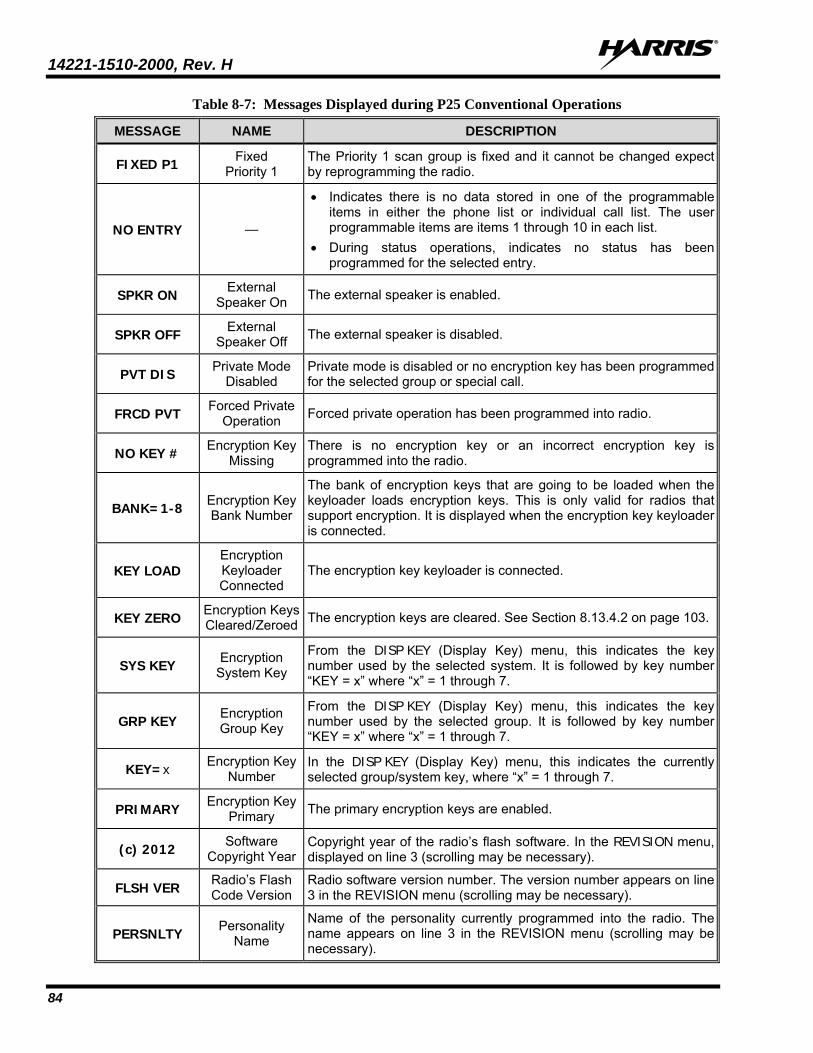
14221-1510-2000, Rev. H
84
Table 8-7: Messages Displayed during P25 Conventional Operations
MESSAGE NAME DESCRIPTION
FIXED P1 Fixed Priority 1
The Priority 1 scan group is fixed and it cannot be changed expect by reprogramming the radio.
NO ENTRY —
• Indicates there is no data stored in one of the programmable items in either the phone list or individual call list. The user programmable items are items 1 through 10 in each list.
• During status operations, indicates no status has been programmed for the selected entry.
SPKR ON External Speaker On The external speaker is enabled.
SPKR OFF External Speaker Off The external speaker is disabled.
PVT DIS Private Mode Disabled
Private mode is disabled or no encryption key has been programmed for the selected group or special call.
FRCD PVT Forced Private Operation Forced private operation has been programmed into radio.
NO KEY # Encryption Key Missing
There is no encryption key or an incorrect encryption key is programmed into the radio.
BANK=1-8 Encryption Key Bank Number
The bank of encryption keys that are going to be loaded when the keyloader loads encryption keys. This is only valid for radios that support encryption. It is displayed when the encryption key keyloader is connected.
KEY LOAD Encryption Keyloader Connected
The encryption key keyloader is connected.
KEY ZERO Encryption Keys Cleared/Zeroed The encryption keys are cleared. See Section 8.13.4.2 on page 103.
SYS KEY Encryption System Key
From the DISP KEY (Display Key) menu, this indicates the key number used by the selected system. It is followed by key number “KEY = x” where “x” = 1 through 7.
GRP KEY Encryption Group Key
From the DISP KEY (Display Key) menu, this indicates the key number used by the selected group. It is followed by key number “KEY = x” where “x” = 1 through 7.
KEY=x Encryption Key Number
In the DISP KEY (Display Key) menu, this indicates the currently selected group/system key, where “x” = 1 through 7.
PRIMARY Encryption Key Primary The primary encryption keys are enabled.
(c) 2012 Software Copyright Year
Copyright year of the radio’s flash software. In the REVISION menu, displayed on line 3 (scrolling may be necessary).
FLSH VER Radio’s Flash Code Version
Radio software version number. The version number appears on line 3 in the REVISION menu (scrolling may be necessary).
PERSNLTY Personality Name
Name of the personality currently programmed into the radio. The name appears on line 3 in the REVISION menu (scrolling may be necessary).
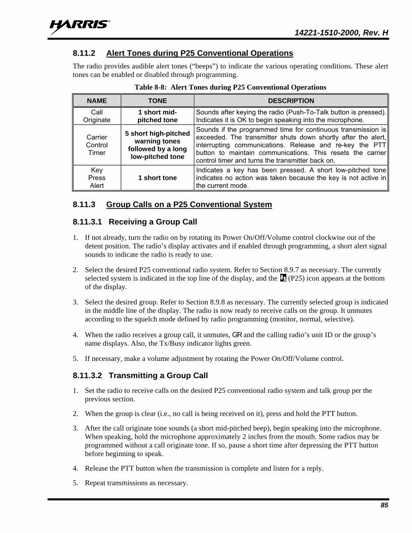
14221-1510-2000, Rev. H
85
8.11.2 Alert Tones during P25 Conventional Operations The radio provides audible alert tones (“beeps”) to indicate the various operating conditions. These alert tones can be enabled or disabled through programming.
Table 8-8: Alert Tones during P25 Conventional Operations
NAME TONE DESCRIPTION Call
Originate 1 short mid- pitched tone
Sounds after keying the radio (Push-To-Talk button is pressed). Indicates it is OK to begin speaking into the microphone.
Carrier Control Timer
5 short high-pitched warning tones
followed by a long low-pitched tone
Sounds if the programmed time for continuous transmission is exceeded. The transmitter shuts down shortly after the alert, interrupting communications. Release and re-key the PTT button to maintain communications. This resets the carrier control timer and turns the transmitter back on.
Key Press Alert
1 short tone Indicates a key has been pressed. A short low-pitched tone indicates no action was taken because the key is not active in the current mode.
8.11.3 Group Calls on a P25 Conventional System
8.11.3.1 Receiving a Group Call
1. If not already, turn the radio on by rotating its Power On/Off/Volume control clockwise out of the detent position. The radio’s display activates and if enabled through programming, a short alert signal sounds to indicate the radio is ready to use.
2. Select the desired P25 conventional radio system. Refer to Section 8.9.7 as necessary. The currently selected system is indicated in the top line of the display, and the (P25) icon appears at the bottom of the display.
3. Select the desired group. Refer to Section 8.9.8 as necessary. The currently selected group is indicated in the middle line of the display. The radio is now ready to receive calls on the group. It unmutes according to the squelch mode defined by radio programming (monitor, normal, selective).
4. When the radio receives a group call, it unmutes, GR and the calling radio’s unit ID or the group’s name displays. Also, the Tx/Busy indicator lights green.
5. If necessary, make a volume adjustment by rotating the Power On/Off/Volume control.
8.11.3.2 Transmitting a Group Call
1. Set the radio to receive calls on the desired P25 conventional radio system and talk group per the previous section.
2. When the group is clear (i.e., no call is being received on it), press and hold the PTT button.
3. After the call originate tone sounds (a short mid-pitched beep), begin speaking into the microphone. When speaking, hold the microphone approximately 2 inches from the mouth. Some radios may be programmed without a call originate tone. If so, pause a short time after depressing the PTT button before beginning to speak.
4. Release the PTT button when the transmission is complete and listen for a reply.
5. Repeat transmissions as necessary.
14221-1510-2000, Rev. H
86
8.11.4 Individual Calls on a P25 Conventional System
8.11.4.1 Receiving and Responding to an Individual Call An individual call is a unit-to-unit radio call which involves only two (2) radios. When the radio receives an individual call from another radio, it unmutes (i.e., audio transmitted from the calling radio is heard in the speaker/headset) and the (Busy) status icon displays. The radio may also be programmed to ring, as described in the next paragraph. Upon receiving an individual call, the radio displays either the logical ID number or the name of the radio unit that originated the individual call. If the originating radio unit’s name is present in the radio (respective to its ID number), the originating radio unit’s name is displayed. If the originating radio unit’s name is not present in the radio (respective to its ID number), the originating radio’s ID number is displayed.
The radio can be programmed to ring when an individual call is received. If so, the ring begins five (5) seconds after the caller (i.e., the originating radio) unkeys and it will continue until the microphone’s PTT button is pressed, or the CLR button is pressed, or the individual call mode is entered. The volume level of the ring is adjustable via the radio’s Power On/Off/Volume control.
The microphone’s hookswitch functions the same as the CLR button in individual call, phone call, and menu modes.
If a response is made to the call by pressing the microphone’s PTT button prior to expiration of the programmed call-back time-out period, the call will be automatically directed to the originating unit via an individual call. If a response is not made before the call-back time-out period expires, the radio will return to normal receive display, and WHC (Who Has Called) will appear in the display.
To respond after expiration of the call-back time-out period, press the programmed Individual Call function key (if programmed) or access this function via the menu. The radio’s display will show the caller’s ID and WHCI=1 (Who Has Called – Individual 1). At this point, pressing the microphone’s PTT button will initiate an individual call back to the original caller.
Pressing the CLR button cancels reception of an individual call and returns the radio to the normal operation. In this case, if the name and/or ID number of the originating radio is not known, the Who Has Called (WHC) list must be accessed in order to call the originating radio back.
Pressing the microphone’s PTT button will initiate an individual call to the displayed logical ID. Powering the radio off and on will clear this list.
The basic procedure to receive an individual call on a P25 conventional radio system is:
1. If not already, turn the radio on by rotating its Power On/Off/Volume control clockwise out of the detent position. The radio’s display activates and if enabled through programming, a short alert signal sounds to indicate the radio is ready to use.
2. Select the desired P25 conventional radio system. Refer to Section 8.9.7 as necessary. The currently selected system is indicated in the top line of the display.
3. The radio is now ready to receive group and individual calls. It unmutes according to the squelch mode defined per radio programming (monitor, normal, selective).
4. When the radio receives an individual call, it unmutes and the unit ID/name of the calling (i.e., transmitting) radio displays.
5. Rotate the Power/On/Off/Volume control to adjust the radio to desired volume level.
NOTE
14221-1510-2000, Rev. H
87
6. Press the PTT button to respond to the caller.
Unanswered individual calls appear in the Who Has Called (WHC) list.
8.11.4.2 Transmitting an Individual Call
1. Press the MENU button to activate the menu function. The programmed menu functions appear in the display. The > symbol at the left of a menu function indicates the currently selected function.
2. Select the desired radio unit for calling from either the Calls Received List (WHCI1 through WHCI10) or a pre-stored unit via the Individual Call (INDV) menu function (if programmed).
To select a pre-stored unit (if programmed) from the Individual Call menu, scroll through the list of pre-stored phone numbers using the + or - buttons until the desired ID number or unit name is displayed, the press the MENU button.
3. Press the microphone’s PTT button. When the radio is clear to transmit turns on, turns off, and the channel access tone sounds. The called individual’s name (or radio ID number) and INDV (Individual) display.
8.11.5 Emergency Group Calls on a P25 Conventional System
When operating on a P25 conventional system, there is no method available for a system-wide emergency clear. An emergency group call must be manually cleared at each radio. See Section 8.11.5.3 that follows for clearing methods that can be used.
8.11.5.1 Receiving an Emergency Group Call
1. If not already, turn the radio on by rotating its Power On/Off/Volume control clockwise out of the detent position. The radio’s display activates and if enabled through programming, a short alert signal sounds to indicate the radio is ready to use. Also depending upon radio programming, the radio powers-up with either the last selected group or the power-up group.
2. Select the desired/required P25 conventional radio system. Refer to Section 8.9.7 as necessary. The currently selected system is indicated in the top line of the display, and the (P25) icon appears at the bottom of the display.
3. Select the desired group. Refer to Section 8.9.8 as necessary. The currently selected group is indicated in the middle line of the display. The radio is now ready to receive calls on the group.
When the radio detects an incoming emergency group call, it sounds an alert tone and RXEMER displays. Voice or emergency transmissions are heard.
8.11.5.2 Declaring an Emergency on a Group
1. Set the radio to receive calls on the desired P25 conventional radio system and talk group per the previous section.
2. Press the red Emergency/Home button on the front of the radio. The radio then broadcasts a short emergency transmission and TXEMER displays.
3. To send a voice message, press the microphone’s PTT button and speak into the microphone.
NOTE
14221-1510-2000, Rev. H
88
8.11.5.3 Clearing an Emergency Clear an emergency using one of the following methods:
• Select another radio system;
• Change channels (if not prohibited by radio programming);
• Cycle radio power by turning the radio off and then back on; or,
• If the radio is programmed with clear emergency privileges, simultaneously press the CLR button and the red Emergency/Home button.
8.11.6 Status Operations on a P25 Conventional System The Status feature allows for the transmission of programmed statuses to the radio system Different statuses can be programmed into the radio and selected one-at-a-time for transmission. Each status is assigned an ID number that is cross-referenced with the representative status condition established by radio system administration personnel. For example, a particular status ID number could be assign as meaning “Off Duty” throughout the radio system. Note that the same ID number could be programmed, for example, as “STATUS 1” in one radio but as “STATUS 5” in another radio. At dispatch consoles in the radio system, the Status feature is typically referred to as Request Status Message (RSM).
One or more radio buttons may be programmed for status operation. For examples, the A button could be programmed to transmit an “En Route” status after it is pressed, the B button could be programmed to transmit an “At Scene” status after it is pressed, and the C button could be programmed to transmit a “Send EMT” status after it is pressed.
To transmit a status, press the respective button to set the status for transmission. After a short delay, the status will be transmitted. Consult with radio system’s network administration personnel for programming information for a specific radio.
Transmission of the status set for transmission can be canceled before the timer expires by pressing the CLR button. This may be necessary if an incorrect status was selected.
When the radio system receives a transmitted status, it sends an acknowledgement message back to the radio and the radio then sounds a high-pitched tone. If the radio system does not receive the status properly, the radio sounds a low-pitched tone upon receipt of the acknowledgement message from the radio system.
8.11.7 Message Operations on a P25 Conventional System The Message feature allows for the transmission of programmed messages to the radio system. Up to ten (10) different messages can be programmed into the radio and selected one-at-a-time for transmission. Each message is assigned an ID number that is cross-referenced with the representative message condition established by radio system administration personnel. For example, a particular message ID number could be assign as meaning “Please Call” throughout the radio system. Note that the same ID number could be programmed, for example, as “MESSAGE 1” in one radio but as “MESSAGE 5” in another radio. At dispatch consoles in the radio system, the Message feature is typically referred to as Request-To-Talk (RTT), since it allows a dispatcher to quickly set-up an individual call back to the radio that transmitted a message.
One or more radio buttons may be programmed for message operation. For examples, the A button could be programmed to transmit a message corresponding to “I-Call ASAP” after it is pressed, and the B button could be programmed to transmit a message corresponding to “Run Plate” after it is pressed.
NOTE
14221-1510-2000, Rev. H
89
To transmit a message, press the respective button to set the message for transmission. After a short delay, the message will be transmitted. Consult with radio system’s network administration personnel for programming information for a specific radio.
Transmission of the message set for transmission can be canceled before the timer expires by pressing the CLR button. This may be necessary if an incorrect message was selected.
When the radio system receives a transmitted message, it sends an acknowledgement message back to the radio. The radio sounds a high-pitched tone upon receiving this acknowledgement message. If the radio system does not receive the message properly, the radio sounds a low-pitched tone upon receipt of the acknowledgement message from the radio system.
NOTE
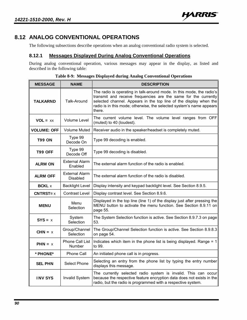
14221-1510-2000, Rev. H
90
8.12 ANALOG CONVENTIONAL OPERATIONS The following subsections describe operations when an analog conventional radio system is selected.
8.12.1 Messages Displayed During Analog Conventional Operations During analog conventional operation, various messages may appear in the display, as listed and described in the following table:
Table 8-9: Messages Displayed during Analog Conventional Operations
MESSAGE NAME DESCRIPTION
TALKARND Talk-Around
The radio is operating in talk-around mode. In this mode, the radio’s transmit and receive frequencies are the same for the currently selected channel. Appears in the top line of the display when the radio is in this mode; otherwise, the selected system’s name appears there.
VOL = xx Volume Level The current volume level. The volume level ranges from OFF (muted) to 40 (loudest).
VOLUME: OFF Volume Muted Receiver audio in the speaker/headset is completely muted.
T99 ON Type 99 Decode On Type 99 decoding is enabled.
T99 OFF Type 99 Decode Off Type 99 decoding is disabled.
ALRM ON External Alarm Enabled The external alarm function of the radio is enabled.
ALRM OFF External Alarm Disabled The external alarm function of the radio is disabled.
BCKL x Backlight Level Display intensity and keypad backlight level. See Section 8.9.5.
CNTRST=x Contrast Level Display contrast level. See Section 8.9.6.
MENU Menu Selection
Displayed in the top line (line 1) of the display just after pressing the MENU button to activate the menu function. See Section 8.9.11 on page 55.
SYS = x System Selection
The System Selection function is active. See Section 8.9.7.3 on page 53.
CHN = x Group/Channel Selection
The Group/Channel Selection function is active. See Section 8.9.8.3 on page 54.
PHN = x Phone Call List Number
Indicates which item in the phone list is being displayed. Range = 1 to 99.
*PHONE* Phone Call An initiated phone call is in progress.
SEL PHN Select Phone Selecting an entry from the phone list by typing the entry number displays this message.
INV SYS Invalid System The currently selected radio system is invalid. This can occur because the respective feature encryption data does not exists in the radio, but the radio is programmed with a respective system.
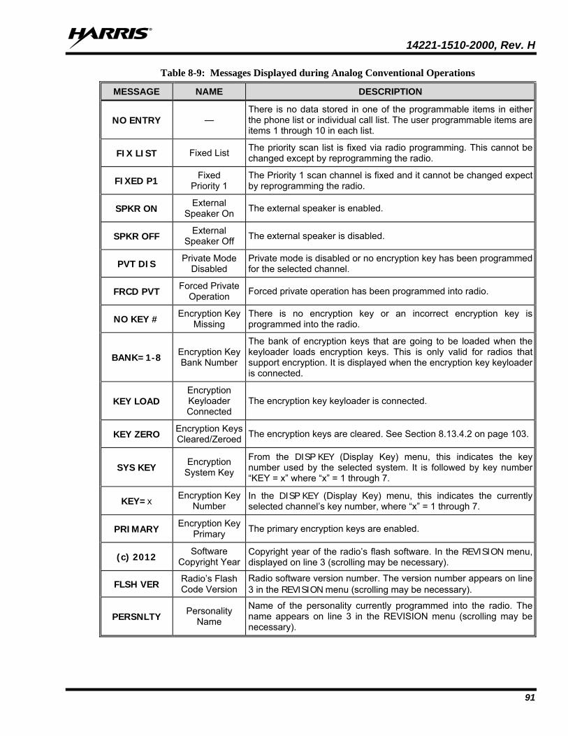
14221-1510-2000, Rev. H
91
Table 8-9: Messages Displayed during Analog Conventional Operations
MESSAGE NAME DESCRIPTION
NO ENTRY — There is no data stored in one of the programmable items in either the phone list or individual call list. The user programmable items are items 1 through 10 in each list.
FIX LIST Fixed List The priority scan list is fixed via radio programming. This cannot be changed except by reprogramming the radio.
FIXED P1 Fixed Priority 1
The Priority 1 scan channel is fixed and it cannot be changed expect by reprogramming the radio.
SPKR ON External Speaker On The external speaker is enabled.
SPKR OFF External Speaker Off The external speaker is disabled.
PVT DIS Private Mode Disabled
Private mode is disabled or no encryption key has been programmed for the selected channel.
FRCD PVT Forced Private Operation Forced private operation has been programmed into radio.
NO KEY # Encryption Key Missing
There is no encryption key or an incorrect encryption key is programmed into the radio.
BANK=1-8 Encryption Key Bank Number
The bank of encryption keys that are going to be loaded when the keyloader loads encryption keys. This is only valid for radios that support encryption. It is displayed when the encryption key keyloader is connected.
KEY LOAD Encryption Keyloader Connected
The encryption key keyloader is connected.
KEY ZERO Encryption Keys Cleared/Zeroed The encryption keys are cleared. See Section 8.13.4.2 on page 103.
SYS KEY Encryption System Key
From the DISP KEY (Display Key) menu, this indicates the key number used by the selected system. It is followed by key number “KEY = x” where “x” = 1 through 7.
KEY=x Encryption Key Number
In the DISP KEY (Display Key) menu, this indicates the currently selected channel’s key number, where “x” = 1 through 7.
PRIMARY Encryption Key Primary The primary encryption keys are enabled.
(c) 2012 Software Copyright Year
Copyright year of the radio’s flash software. In the REVISION menu, displayed on line 3 (scrolling may be necessary).
FLSH VER Radio’s Flash Code Version
Radio software version number. The version number appears on line 3 in the REVISION menu (scrolling may be necessary).
PERSNLTY Personality Name
Name of the personality currently programmed into the radio. The name appears on line 3 in the REVISION menu (scrolling may be necessary).
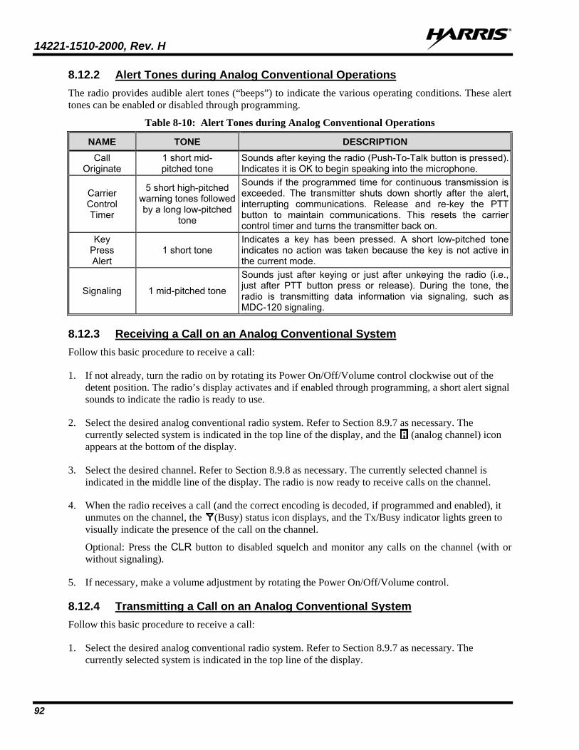
14221-1510-2000, Rev. H
92
8.12.2 Alert Tones during Analog Conventional Operations The radio provides audible alert tones (“beeps”) to indicate the various operating conditions. These alert tones can be enabled or disabled through programming.
Table 8-10: Alert Tones during Analog Conventional Operations
NAME TONE DESCRIPTION Call
Originate 1 short mid- pitched tone
Sounds after keying the radio (Push-To-Talk button is pressed). Indicates it is OK to begin speaking into the microphone.
Carrier Control Timer
5 short high-pitched warning tones followed by a long low-pitched
tone
Sounds if the programmed time for continuous transmission is exceeded. The transmitter shuts down shortly after the alert, interrupting communications. Release and re-key the PTT button to maintain communications. This resets the carrier control timer and turns the transmitter back on.
Key Press Alert
1 short tone Indicates a key has been pressed. A short low-pitched tone indicates no action was taken because the key is not active in the current mode.
Signaling 1 mid-pitched tone
Sounds just after keying or just after unkeying the radio (i.e., just after PTT button press or release). During the tone, the radio is transmitting data information via signaling, such as MDC-120 signaling.
8.12.3 Receiving a Call on an Analog Conventional System Follow this basic procedure to receive a call:
1. If not already, turn the radio on by rotating its Power On/Off/Volume control clockwise out of the detent position. The radio’s display activates and if enabled through programming, a short alert signal sounds to indicate the radio is ready to use.
2. Select the desired analog conventional radio system. Refer to Section 8.9.7 as necessary. The currently selected system is indicated in the top line of the display, and the (analog channel) icon appears at the bottom of the display.
3. Select the desired channel. Refer to Section 8.9.8 as necessary. The currently selected channel is indicated in the middle line of the display. The radio is now ready to receive calls on the channel.
4. When the radio receives a call (and the correct encoding is decoded, if programmed and enabled), it unmutes on the channel, the (Busy) status icon displays, and the Tx/Busy indicator lights green to visually indicate the presence of the call on the channel.
Optional: Press the CLR button to disabled squelch and monitor any calls on the channel (with or without signaling).
5. If necessary, make a volume adjustment by rotating the Power On/Off/Volume control.
8.12.4 Transmitting a Call on an Analog Conventional System Follow this basic procedure to receive a call:
1. Select the desired analog conventional radio system. Refer to Section 8.9.7 as necessary. The currently selected system is indicated in the top line of the display.
14221-1510-2000, Rev. H
93
2. Select the desired channel. Refer to Section 8.9.8 as necessary. The currently selected channel is indicated in the middle line of the display. The radio is now ready to receive calls on the channel.
3. Verify the channel is not busy (i.e., no call currently exists on it) by observing for the lack of the (Busy) status icon in the display. If this icon is present in the display, do not proceed until it disappears.
For an analog convention channel, a channel’s busy/not busy status can also be checked by briefly depressing the radio’s CLR button. This disables squelch and any channel programmed decoding and unmutes the receiver. Therefore, any signals received on the channel can be heard in the speaker/headset.
If the Channel Busy Lockout feature is programmed for the selected channel, the radio will not transmit when the channel is busy
4. Press and hold the microphone’s PTT button. If the Call Originate (sometimes called Ready-To-Talk) alert tone is programmed, the radio will sound a short beep tone when it begins transmitting on the channel.
5. Hold the microphone approximately 2 inches from the mouth and speak into it in a normal voice.
6. When the transmission is complete, release the PTT button and listen for a reply.
7. Repeat transmissions as necessary.
8.12.5 Scanning Channels on an Analog Conventional System Channels which have been previously added to the scan list on a per radio system basis, can be scanned. The selected channel is scanned (if enabled through programming) whether or not it is in the scan list. Each conventional radio system’s channel scan list is retained in memory when the radio is turned off.
The scan rate varies depending upon the number of channels in the scan list and whether or not the radio is programmed to scan for channels with decoding enabled. Fewer channels results in a faster scan rate. If programmed for dual-priority scan operation, the priority 1, priority 2, and the remaining scan list channels are scanned. Once a signal is detected and the correct encoded squelch signal is decoded (if programmed), the radio receives the message and displays the received scan channel. At the same time, scanning continues on the priority 1 and priority 2 channels. If a priority 1 or priority 2 channel carrier, regardless of encoded squelch decoding, is detected while a non-priority channel is being received, the display name is updated and the received channel is switched to the priority channel. Scanning of the priority 1 channel continues if a message is being received on the priority 2 channel.
While receiving a call on a non-priority or a priority 2 channel, the radio periodically checks the priority 1 and 2 channels. If scan with Channel Guard is enabled, the radio uses Channel Guard to decide whether to unmute on a priority channel. The radio stops, on squelch detection, on a priority channel. In normal operation, the radio unmutes only on detecting the correct Channel Guard; otherwise, it remains muted until the priority channel call and hang time have ended. An optional feature allows the radio to continue scanning upon the detection of the wrong Channel Guard on a priority channel. The user can then select the rate at which this channel is scanned until the call ends.
NOTE
NOTE
14221-1510-2000, Rev. H
94
8.12.5.1 Turning Scan On and Off Toggle scan operation on and off by selecting the SCAN function. Typically, this is performed by pressing the SCAN button, if so programmed. This function may also be programmed to the radio’s conventional menu. When the radio is scanning channels (i.e., when scan is on), the (Scan) icon rotates in the bottom line of the display and the radio scans the channels currently on the conventional scan list.
Scanning stops when the radio is receiving or transmitting a call. Scanning also stops while the microphone is off-hook if the hookswitch function is enabled via radio programming.
When a channel on the scan list has an active call, the radio unmutes, the Tx/Busy indicator lights green, and the call is heard in the radio’s speaker/headset.
The radio continues scanning if a new channel is selected when scan is on. If the radio is receiving a call on a non-selected channel when scan is turned off, it returns to the selected channel.
Pressing the PTT button when scan is on causes the radio to transmit on the displayed channel or on the currently selected channel, depending on programming.
When the radio is scanning, selecting the SCAN ADD function (if programmed) recalls the scanned channel that last received a call. This channel is recalled for a period equal to the scan hang-time. This function may be programmed to the radio’s conventional menu or to a radio button.
When scan is turned off, the radio resumes operation on the selected channel.
8.12.5.2 Adding Channels to the Scan List Either the SCAN ADD function or the SCAN A/D (add/delete) function can be used to add a channel to the scan list and change its scan priority level. This procedure assumes the desired channel for adding to the scan list is programmed in the currently selected system but not currently on the scan list. Also, it is assumed the radio is not programmed with a fixed scan list.
1. Turn scan off, if it is not already off. This can be accomplished by pressing the button programmed with the SCAN function (typically the SCAN button) or, if programmed, by selecting this function on the menu. When scan is off, the icon is not displayed.
2. Select the SCAN ADD function or the SCAN A/D function to add the currently selected channel to the scan list as a non-priority scan channel. Either function may be programmed to a radio button or on the menu. When set as a non-priority scan channel, the icon (non-priority scan icon = 3 bars) appears at the bottom of the display.
If neither function is programmed, it is not possible to add the channel to the scan list unless the radio is re-programmed.
If the radio displays FIXED LST, it is programmed with a fixed scan list and this list cannot be changed without radio re-programming.
3. If desired, select the same function again to set the channel as the Priority 2 scan channel. The icon (Priority 2 scan icon = 2 bars) appears at the bottom of the display.
4. If desired, select the same function again to set the channel as the Priority 1 scan channel. The icon (Priority 1 scan icon = 1 bar) appears at the bottom of the display.
NOTE
NOTE
14221-1510-2000, Rev. H
95
If the radio displays FIXED P1, a channel has been programmed as the fixed Priority 1 channel. In this case, another channel cannot be set as the Priority 1 channel, and the fixed Priority 1 channel cannot be changed from the Priority 1 channel unless the radio is re-programmed.
5. Another channel can be added to the list by selecting the channel and then repeating from step 2.
6. If desired, turn scan on by selecting the SCAN function.
If the Priority 1 and Priority 2 channels were already set and a new channel is assigned as the Priority 1 or the Priority 2 scan channel, then the previously assigned channel changes to non-priority scanning.
When using the SCAN ADD function, the priority level selection sequence advances the channel to the next higher priority level and stops at Priority 1. To select a lower priority level, the channel must be deleted from the scan list (using the SCAN DEL function or the SCAN A/D function) and then added back to the scan list. Each new channel added to the scan list starts at the non-priority level (i.e., the lowest level).
When using the SCAN A/D function, the priority level selection sequence wraps from Priority 1 to no scan. Since this function can both add and delete, it may be desired so other functions can be programmed to the limited number of radio buttons.
8.12.5.3 Deleting Channels from the Scan List Either the SCAN DEL (scan delete) function or the SCAN A/D (scan add/delete) function can be used to delete a channel from the scan list. The SCAN A/D function can also be used to change the channel’s scan priority level. This procedure assumes the desired channel for deleting from the scan list is programmed in the currently selected system and currently on the scan list. Also, it is assumed the radio is not programmed with a fixed scan list.
1. Turn scan off, if it is not already off. This can be accomplished by pressing the button programmed with the SCAN function (typically the SCAN button) or, if programmed, by selecting this function on the menu. When scan is off, the icon is not displayed.
2. If programmed, select the SCAN DEL function once to delete/remove the channel from the scan list. The scan icon clears from the display when this function is selected.
Alternately, select the SCAN A/D function one or more times until no scan icons (i.e., no bars) appear in the display. At this point, the channel is removed from the scan list.
If neither function is programmed, it is not possible to delete the channel from the scan list unless the radio is re-programmed.
3. If desired, turn scan on by selecting the SCAN function.
NOTE
14221-1510-2000, Rev. H
96
8.12.5.4 Nuisance Delete If not the currently selected channel, a channel can be temporarily deleted from the scan list by selecting the SCAN DEL (Scan Delete) function when the radio is scanning and receiving a call on the unwanted channel. This action prevents calls from being received on the unselected channel, since the channel is temporarily removed from the scan list. Deletions performed in this manner do not remain deleted after the radio’s power is cycled. The Scan Delete function may be programmed to a radio button, or menu, or both.
8.12.6 Squelch Adjustment for an Analog Conventional System In the conventional mode of operation, the radio’s receiver squelch setting can be adjusted via the menu (if programmed) or via a button that has been programmed with the Squelch function. The default squelch setting is nine (9). Any setting between one (1) and sixteen (16) can be selected if the Squelch function is available. Whenever a channel has an active call, the Tx/Busy indicator lights green.
A setting of sixteen (16) requires a very strong signal to open squelch (i.e., to unmute the radio), a setting of approximately five (5) requires a very weak signal to open squelch, and a setting of one (1) is open squelch. Numbers will vary from radio-to-radio and per existing radio frequency conditions.
When the squelch adjust function is activated, Channel Guard, T99 decode, and Scan are disabled. When the squelch adjust function is exited, Channel Guard, T99 decode, and Scan are restored to their previous states.
1. Press the MENU button to activate the menu function.
Alternately, if another button such as one (1) of the three (3) preset buttons is programmed with the Squelch function, press this button and advance to step 3.
2. Press the + or – buttons to scroll through the menu until SQUELCH is selected with the > symbol, and then press the MENU button again.
3. SQLCH=xx, where xx is the current squelch setting appears in the second line of the display. The range is 1 to 16. Press the + or – buttons to increase or decrease the current squelch setting as required. Higher settings require a stronger received signal to open squelch.
4. Press the MENU button again to save the new setting and return to a normal display. If the MENU button is not pressed after a short period, menu selection automatically exits and the new squelch setting is not saved.
8.12.7 Type 99 Decoding on an Analog Conventional System
8.12.7.1 General Information Type 99 is a form of selective signaling. Selective signaling controls the muting and unmuting of receiver audio via sequential tone signals sent over radio channels. Radio base stations, mobile radios or portable radios with Type 99 encode capability can selectively call individual radio units or groups of radio units in an analog conventional radio system. Type 99 is typically used in paging operations so a dispatcher can
NOTE
NOTE
14221-1510-2000, Rev. H
97
selectively call a radio or a group of radios. If the radio is programmed for Type 99 decoding and this decoding is on (enabled), the radio can decode individual, group, and supergroup Type 99 calls.
To perform Type 99 decoding operations, Type 99 tone sequences must be programmed into the radio and at least one conventional channel must be programmed for Type 99 decode operations.
When the radio decodes an appropriate Type 99 code sequence, the radio sounds an alert tone and it displays an appropriate indication. The receiver then operates with noise squelched until Type 99 decoding is reset. Type 99 decoding continues to operate during this noise squelched period. The appropriate Type 99 alert tone sounds again if it detects a valid tone sequence. Whenever a channel has an active call, the Tx/Busy indicator lights green.
Type 99 operation can be manually or automatically reset (programmable). Manual reset is achieved by briefly pressing the CLR button (if it is programmed with the MON CLR function). Automatic reset, if programmed, occurs after a 30-second interval following the most recent decode of a Type 99 tone sequence.
Type 99 decoding continues to be active while the CLR button is pressed (if it is programmed with the MON CLR function). This allows the user to monitor calls and still be alerted when a call is directed to the radio. While the CLR button is pressed, calls and all Type 99 tone signals are heard in the speaker/headset. If the CLR button is pressed for longer than two (2) seconds, Type 99 decoding is either turned off or back on (disabled or re-enabled) depending upon its present state.
If an alert option is installed and enabled along with Type 99 decoding, the radio can be wired and programmed to activate a vehicle device such as a horn or light when a proper Type 99 call is received and decoded. This option permits alerting of persons outside of the vehicle via Type 99 signaling.
Type 99 decoding is automatically turned off (disabled) when the radio is scanning (i.e., when scan is on/enabled).
8.12.7.2 Turning Type 99 Decoding On and Off When Type 99 decoding is off, it is disabled and considered to be in the “monitor” state. When Type 99 decoding is on, it is enabled and considered to be in the “selective call” state. When on, the (Type 99) icon appears at the bottom of the display.
If the radio is programmed for Type 99 decoding operation, it is typically programmed so Type 99 decoding can be manually turned on and off. Refer to the following subsections for details.
The radio can also be programmed so microphone hookswitch activation will turn Type 99 decoding on and off. If so, decoding turns off when the mic is off hook and on when the mic is on hook.
In addition, the radio can also be programmed to automatically turn Type 99 decoding off for 30 seconds when the microphone’s PTT button is pressed. This allows subsequent call responses without valid tone sequences to be heard.
As previously noted, Type 99 decoding automatically turns off when the radio is scanning.
Radio programming allows each analog conventional channel to be programmed to support or to not support Type 99 decoding operations. By default, if a channel is programmed to support Type 99 decoding, Type 99 decoding automatically turns on when the channel is selected. If the selected channel is not programmed for Type 99 decoding, the radio sounds a low-pitched tone if an attempt is made to manually turn it on.
NOTE
14221-1510-2000, Rev. H
98
8.12.7.2.1 With a Button If a radio button is programmed so Type 99 decoding can be manually turned on and off, first select a channel programmed to support Type 99 decoding and then press that button. If Type 99 decoding was off, it toggles on and T99 ON briefly displays in the top line of the display. If Type 99 decoding was on, it toggles off and T99 OFF briefly displays in the top line of the display. When Type 99 decoding is on, the (Type 99) icon appears at the bottom of the display.
8.12.7.2.2 With the Menu If the T99 EN (Type 99 Enable) function is programmed on the conventional menu, turn Type 99 decoding on and off as follows:
1. Select the desired/required channel programmed to support Type 99 decoding.
2. Press the MENU button to activate the menu function.
3. Press the + or – buttons to scroll through the menu until T99 EN is selected with the > symbol.
4. Press the MENU button to toggle the Type 99 decoding state between on and off. If Type 99 decoding was off, it toggles on and T99 ON briefly displays in the top line of the display. If Type 99 decoding was on, it toggles off and T99 OFF briefly displays in the top line of the display. When on, the (Type 99) icon appears at the bottom of the display.
8.12.7.3 Type 99 With or Without Channel Guard Selective signaling operates with or without Channel Guard. If Channel Guard is enabled, the radio can be programmed with an “And” or an “Or” option, determined by programming with the T99 Mute Control feature:
• If the “And” option is programmed, T99 calls require the correct selective signaling (T99 tone sequence) and the correct Channel Guard tones before the radio will unsquelch.
• If the “Or” option is programmed, a call with the correct Channel Guard tone or with the correct T99 tone sequence will unsquelch the radio.
8.12.7.4 Resetting Type 99 After a Decoded Call Type 99 operation can be manually or automatically reset (programmable). Manual reset is achieved by briefly pressing the CLR button (if it is programmed with the MON CLR function). Automatic reset, if programmed, occurs after a 30-second interval following the most recent decode of a Type 99 tone sequence.
8.12.7.5 Type 99 Disable After Radio PTT The radio may be programmed with the Type 99 Disable After PTT feature. This feature automatically disables the Type 99 decoder (i.e., turns Type 99 decoding off) after a radio transmission.
8.12.8 MDC-1200 Signaling On An Analog Conventional System The radio supports MDC-1200 signaling, including functions such as PTT ID and emergency. This feature can be enabled on a per-channel basis. Both MDC-1200 encode and MDC-1200 decode operations are supported.
14221-1510-2000, Rev. H
99
8.12.8.1 Transmission (Encode) Along with voice audio, the radio can be programmed to transmit an MDC-1200-encoded identification (ID) number on the selected channel with each press/release of the microphone’s PTT button. This function is commonly referred to a “PTT ID.” This allows a radio to be identified with a unique number throughout the radio system upon each transmission. Per radio programming, the ID number can be sent when the mic’s PTT button is pressed (i.e., before voice audio is transmitted), when the mic’s PTT button is released (i.e., after voice audio is transmitted), or at both PTT press and release.
The radio can be programmed to sound either a long or a short tone just prior to transmitting an MDC-1200 signal. The long tone lasts approximately two seconds and the short tone lasts approximately one-quarter of a second. When the tone sounds, remain keyed (i.e., keep the mic’s PTT button depressed) but do not begin speaking into the mic. When the tone ends, begin speaking into the mic and then release the PTT button when speaking is done. Consult with radio system’s network administration personnel for programming information for a specific radio.
The radio can also be programmed with a “system pre-time” of between approximately 0 and 6.5 seconds. The programmed time specifies the time delay between when the mic’s PTT is initially pressed (and the radio begins transmitting) and when the MDC signaling is broadcast on the selected channel. For example, if the radio’s programmed system pre-time is 3 seconds, MDC-1200 signaling is broadcast 3 seconds after keying the radio on a channel programmed for MDC-1200 operation. Consult with radio system’s network administration personnel for programming information for a specific radio.
8.12.8.2 Receive (Decode) The radio can be programmed to momentarily display MDC-1200 signaling information it receives. After decoding a received PTT ID number on the selected channel, the radio displays either the received ID number or the name corresponding to the transmitting radio. If the name for the ID number is programmed into the radio, the name will be displayed when the ID number is received. Otherwise, the received ID number is displayed. Consult with radio system’s network administration personnel for programming information for a specific radio.
The period of time that the ID number/name remains displayed is programmable between 0 and 10 seconds. This is the “MDC hang time” setting. The default value is 7 seconds. If programmed at 0 seconds, no ID number/name is displayed when an ID number is received. Consult with radio system’s network administration personnel for programming information for a specific radio.
8.12.9 Emergency Calls On An Analog Conventional System
8.12.9.1 G-STAR Emergency Signaling If enabled, G-STAR emergency signaling can be transmitted when operating in the analog conventional mode. This G-STAR signaling transmits five (5) times with a delay between each transmission. To send an emergency call on the selected analog conventional radio system and channel (or on an optionally programmed analog conventional emergency system and channel), proceed as follows. It is assumed the radio is programmed for G-STAR emergency signaling.
Press and hold the red Home/Emergency button for approximately one second. This time is programmable; therefore, it could be longer or shorter. Consult with the radio system’s network administration personnel for programming information for a specific radio. The radio turns on the Tx/Busy indicator lights red and it proceeds to transmit the programmed G-STAR emergency signaling sequence.
14221-1510-2000, Rev. H
100
G-STAR is programmed to transmit in one of the following methods:
Method 1: G-STAR is transmitted on the selected channel. If the channel is changed the emergency signaling continues to be transmitted on the newly selected channel.
Method 2: Same as Method 1 except the radio locks on to the currently selected channel. Attempts to change the system or channel are disabled.
Method 3: G-STAR is transmitted on a programmed analog conventional emergency radio system and channel regardless of the selected channel. In this case, the selected channel is available for voice transmission and the radio periodically changes to the programmed emergency radio system and channel to send the emergency signaling and then it changes back to the selected channel.
Method 4: Same as Method 3, except the radio locks on to the programmed emergency radio system and channel. Attempts to change the radio system or channel are disabled.
The emergency state can be cleared by turning the radio off and then back on.
8.12.9.2 5-Tone Emergency Signalling If 5-tone emergency signaling is defined for emergency declaration in place of G-STAR emergency signaling, a programmed tone sequence is transmitted instead of the G-STAR sequence. This emergency declaration functions as the G-STAR emergency in all other respects.
8.12.9.3 Tone Encode Transmission In analog conventional mode, two keys can be defined to be tone encode triggers. If either one of the programmed tone encode triggers is pressed, a programmed tone sequence is transmitted on the current radio system and channel. See Section 8.12.9 if the Emergency/Home key is used. The Tx/Busy indicator lights red during the tone transmission and a beep sounds at the end of the transmission. If enabled, audible side tones are heard in the radio speaker/headset as well. If PTT is programmed as one of the triggers, the microphone becomes active for voice communication after the tone sequence is complete.
Tone encode is transmitted with Channel Guard if one is defined, and tones are always transmitted in clear voice mode, even if the channel is set for digital or private. Digital or private voice transmission resumes normally after the tone transmission.
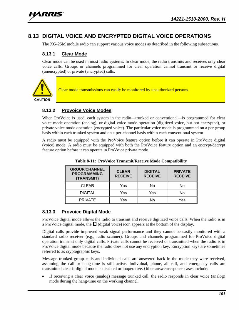
14221-1510-2000, Rev. H
101
8.13 DIGITAL VOICE AND ENCRYPTED DIGITAL VOICE OPERATIONS The XG-25M mobile radio can support various voice modes as described in the following subsections.
8.13.1 Clear Mode Clear mode can be used in most radio systems. In clear mode, the radio transmits and receives only clear voice calls. Groups or channels programmed for clear operation cannot transmit or receive digital (unencrypted) or private (encrypted) calls.
Clear mode transmissions can easily be monitored by unauthorized persons.
8.13.2 Provoice Voice Modes When ProVoice is used, each system in the radio—trunked or conventional—is programmed for clear voice mode operation (analog), or digital voice mode operation (digitized voice, but not encrypted), or private voice mode operation (encrypted voice). The particular voice mode is programmed on a per-group basis within each trunked system and on a per-channel basis within each conventional system.
A radio must be equipped with the ProVoice feature option before it can operate in ProVoice digital (voice) mode. A radio must be equipped with both the ProVoice feature option and an encrypt/decrypt feature option before it can operate in ProVoice private mode.
Table 8-11: ProVoice Transmit/Receive Mode Compatibility
GROUP/CHANNEL PROGRAMMING
(TRANSMIT) CLEAR
RECEIVE DIGITAL RECEIVE
PRIVATE RECEIVE
CLEAR Yes No No
DIGITAL Yes Yes No
PRIVATE Yes No Yes
8.13.3 Provoice Digital Mode ProVoice digital mode allows the radio to transmit and receive digitized voice calls. When the radio is in a ProVoice digital mode, the (digital voice) icon appears at the bottom of the display.
Digital calls provide improved weak signal performance and they cannot be easily monitored with a standard radio receiver (e.g., radio scanner). Groups and channels programmed for ProVoice digital operation transmit only digital calls. Private calls cannot be received or transmitted when the radio is in ProVoice digital mode because the radio does not use any encryption key. Encryption keys are sometimes referred to as cryptographic keys.
Message trunked group calls and individual calls are answered back in the mode they were received, assuming the call or hang-time is still active. Individual, phone, all call, and emergency calls are transmitted clear if digital mode is disabled or inoperative. Other answer/response cases include:
• If receiving a clear voice (analog) message trunked call, the radio responds in clear voice (analog) mode during the hang-time on the working channel.
14221-1510-2000, Rev. H
102
• If receiving a clear voice (analog) individual call, the radio responds in clear voice (analog) mode during the hang time.
• When using the Who Has Called (WHC) feature to respond to an individual call (after the hang time has expired), the call is transmitted in the mode defined by the system mode as programmed for the current system if the ID being called is not in the radio’s individual call list. If the ID is in the list, then the call is transmitted as defined by the individual call mode programmed in the list for that ID.
8.13.4 Private Mode Private mode can be employed in any radio system that can support encrypted voice operations. Encryption protects against unauthorized reception of radio communications. When the radio is in private mode, the (encryption) icon appears at the bottom of the display.
The XG-25M mobile radio supports both the Advanced Encryption Standard (AES) and the Data Encryption Standard. DES encryption uses 56-bit keys, while AES uses 128, 192, or 256-bit keys. Since every additional bit doubles the number of keys that must be attempted for decoding, this makes AES significantly more robust than DES.
Private mode sets the radio to transmit encrypted calls and to receive both clear and encrypted calls. The radio transmits private if the group/channel is programmed for private operation and forced operation is programmed.
If the radio is programmed for auto-select, the radio transmits as follows:
• If private mode is enabled, transmissions are always in private mode.
• If private mode is disabled and a private call is received, the reply transmission is in private mode if the transmission is made during the scan hang-time. If the reply transmission occurs after the scan hang-time, the transmission is in clear mode.
When operating on a group or channel programmed for private mode, all transmissions are private and the radio receives clear and private calls. If the selected group or channel is programmed for auto-select capability, the mode can be toggled between private and clear by selecting the PVT function (programmed menu or button). Radios programmed for forced private operation do not allow a change of the transmit mode; therefore, this button has no effect.
8.13.4.1 Displaying the Number of the Currently Used Encryption Key The number of the encryption key currently in use can be displayed. This is either the number of the system encryption key (for special calls such as individual, phone, all, agency or fleet) or the number of the group/channel key (for group or conventional calls). Each number is a storage location number in the radio for the key, not the actual encryption key.
1. Press the MENU button to activate the menu function. The programmed menu functions appear in the display. The > symbol at the left of a menu function indicates the currently selected function.
2. Press the + or – buttons to scroll and select the DSP KEY function.
3. Press the MENU button again.
4. Press the + or – buttons to toggle between displaying the number of the system key or the number of the group/channel key.
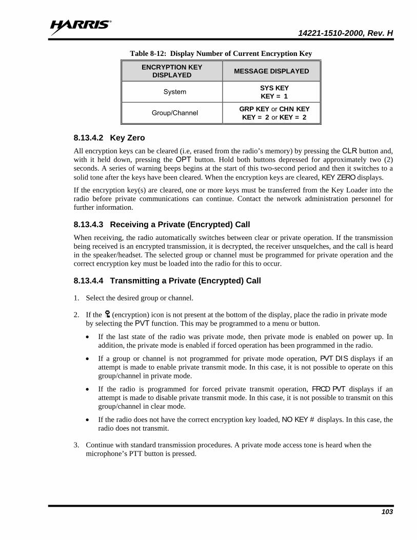
14221-1510-2000, Rev. H
103
Table 8-12: Display Number of Current Encryption Key
ENCRYPTION KEY DISPLAYED MESSAGE DISPLAYED
System SYS KEY KEY = 1
Group/Channel GRP KEY or CHN KEY KEY = 2 or KEY = 2
8.13.4.2 Key Zero All encryption keys can be cleared (i.e, erased from the radio’s memory) by pressing the CLR button and, with it held down, pressing the OPT button. Hold both buttons depressed for approximately two (2) seconds. A series of warning beeps begins at the start of this two-second period and then it switches to a solid tone after the keys have been cleared. When the encryption keys are cleared, KEY ZERO displays.
If the encryption key(s) are cleared, one or more keys must be transferred from the Key Loader into the radio before private communications can continue. Contact the network administration personnel for further information.
8.13.4.3 Receiving a Private (Encrypted) Call When receiving, the radio automatically switches between clear or private operation. If the transmission being received is an encrypted transmission, it is decrypted, the receiver unsquelches, and the call is heard in the speaker/headset. The selected group or channel must be programmed for private operation and the correct encryption key must be loaded into the radio for this to occur.
8.13.4.4 Transmitting a Private (Encrypted) Call
1. Select the desired group or channel.
2. If the (encryption) icon is not present at the bottom of the display, place the radio in private mode by selecting the PVT function. This may be programmed to a menu or button.
• If the last state of the radio was private mode, then private mode is enabled on power up. In addition, the private mode is enabled if forced operation has been programmed in the radio.
• If a group or channel is not programmed for private mode operation, PVT DIS displays if an attempt is made to enable private transmit mode. In this case, it is not possible to operate on this group/channel in private mode.
• If the radio is programmed for forced private transmit operation, FRCD PVT displays if an attempt is made to disable private transmit mode. In this case, it is not possible to transmit on this group/channel in clear mode.
• If the radio does not have the correct encryption key loaded, NO KEY # displays. In this case, the radio does not transmit.
3. Continue with standard transmission procedures. A private mode access tone is heard when the microphone’s PTT button is pressed.
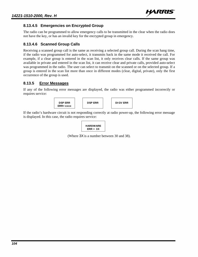
14221-1510-2000, Rev. H
104
8.13.4.5 Emergencies on Encrypted Group The radio can be programmed to allow emergency calls to be transmitted in the clear when the radio does not have the key, or has an invalid key for the encrypted group in emergency.
8.13.4.6 Scanned Group Calls Receiving a scanned group call is the same as receiving a selected group call. During the scan hang time, if the radio was programmed for auto-select, it transmits back in the same mode it received the call. For example, if a clear group is entered in the scan list, it only receives clear calls. If the same group was available in private and entered in the scan list, it can receive clear and private calls, provided auto-select was programmed in the radio. The user can select to transmit on the scanned or on the selected group. If a group is entered in the scan list more than once in different modes (clear, digital, private), only the first occurrence of the group is used.
8.13.5 Error Messages If any of the following error messages are displayed, the radio was either programmed incorrectly or requires service:
DSP ERR
ERR=xxxx
DSP ERR
DIGV ERR
If the radio’s hardware circuit is not responding correctly at radio power-up, the following error message is displayed. In this case, the radio requires service:
HARDWARE
ERR = 3X
(Where 3X is a number between 30 and 38).
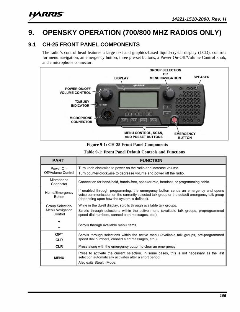
14221-1510-2000, Rev. H
105
9. OPENSKY OPERATION (700/800 MHZ RADIOS ONLY) 9.1 CH-25 FRONT PANEL COMPONENTS
The radio’s control head features a large text and graphics-based liquid-crystal display (LCD), controls for menu navigation, an emergency button, three pre-set buttons, a Power On-Off/Volume Control knob, and a microphone connector.
Figure 9-1: CH-25 Front Panel Components
Table 9-1: Front Panel Default Controls and Functions
PART FUNCTION
Power On-Off/Volume Control
Turn knob clockwise to power on the radio and increase volume. Turn counter-clockwise to decrease volume and power off the radio.
Microphone Connector Connection for hand-held, hands-free, speaker-mic, headset, or programming cable.
Home/Emergency Button
If enabled through programming, the emergency button sends an emergency and opens voice communication on the currently selected talk group or the default emergency talk group (depending upon how the system is defined).
Group Selection/ Menu Navigation
Control
While in the dwell display, scrolls through available talk groups. Scrolls through selections within the active menu (available talk groups, preprogrammed speed dial numbers, canned alert messages, etc.).
+ –
Scrolls through available menu items.
OPT CLR
Scrolls through selections within the active menu (available talk groups, pre-programmed speed dial numbers, canned alert messages, etc.).
CLR Press along with the emergency button to clear an emergency.
MENU Press to activate the current selection. In some cases, this is not necessary as the last selection automatically activates after a short period. Also exits Stealth Mode.
14221-1510-2000, Rev. H
106
PART FUNCTION
Display Area
Menu selections and messages. Network Connectivity icon. RSSI Indicator. Current Volume Level icon. Volume represented numerically within the display (0 = Muted, 40 = Loudest). User may select which one of several dwell displays the radio uses.
Pre-Set Buttons A, B, & C
These buttons are used to store and recall user-selectable parameters such as scan mode, selected profile, selected talk group, and priority talk group. Different parameters can be stored at each of the three different pre-set buttons. Preset button C can be configured via programming to reboot the radio into a particular application mode. Contact your system administrator to determine if this feature is enabled in your radio.
SCAN
Toggles the Scan Mode ON/OFF. • If the Scan Mode is Normal and the Scan Mode is toggled off, when the Scan Mode is
toggled On the Scan Mode is set to Normal. • If the Scan Mode is Fixed and the Scan Mode is toggled off, when the Scan Mode is
toggled On the Scan Mode is set to Fixed.
• If the Scan Mode is off when the radio boots up when the Scan Mode is toggled On the Scan Mode is set to Normal.
9.2 POWER UP AND VOLUME CONTROL
9.2.1 Power Up
1. Rotate the Power On-Off/Volume Control knob clockwise to power on the radio. The display illuminates when the radio powers up.
2. Wait for the power-up sequence to complete, which takes approximately ten (10) seconds. During this time, if enabled for auto registration, the radio is provisioned with a customized user personality designed for the user’s specific needs by the OpenSky network administrator.
3. When provisioning is complete, the radio displays the Dwell Display.
9.2.2 Volume Control Turn the Power On-Off/Volume Control knob clockwise to increase the volume and counter-clockwise to decrease the volume. The radio sounds a tone to indicate the current volume level.
9.3 SELF-TEST After power-up, the XG-25M radio undergoes a multi-function automatic registration procedure. As many as sixteen (16) possible radio profiles are downloaded to the radio from the network in response to the User’s ID.
9.4 LOG IN TO THE NETWORK Log in occurs automatically (auto registration) if the radio has a valid registration.
9.5 LOG OFF THE NETWORK Log off is automatically performed when powering down the radio.
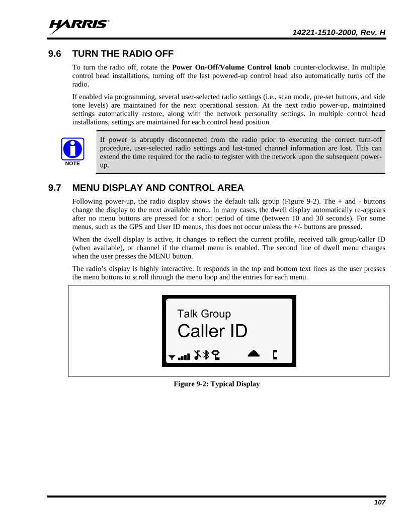
14221-1510-2000, Rev. H
107
9.6 TURN THE RADIO OFF To turn the radio off, rotate the Power On-Off/Volume Control knob counter-clockwise. In multiple control head installations, turning off the last powered-up control head also automatically turns off the radio.
If enabled via programming, several user-selected radio settings (i.e., scan mode, pre-set buttons, and side tone levels) are maintained for the next operational session. At the next radio power-up, maintained settings automatically restore, along with the network personality settings. In multiple control head installations, settings are maintained for each control head position.
If power is abruptly disconnected from the radio prior to executing the correct turn-off procedure, user-selected radio settings and last-tuned channel information are lost. This can extend the time required for the radio to register with the network upon the subsequent power-up.
9.7 MENU DISPLAY AND CONTROL AREA Following power-up, the radio display shows the default talk group (Figure 9-2). The + and - buttons change the display to the next available menu. In many cases, the dwell display automatically re-appears after no menu buttons are pressed for a short period of time (between 10 and 30 seconds). For some menus, such as the GPS and User ID menus, this does not occur unless the +/- buttons are pressed.
When the dwell display is active, it changes to reflect the current profile, received talk group/caller ID (when available), or channel if the channel menu is enabled. The second line of dwell menu changes when the user presses the MENU button.
The radio’s display is highly interactive. It responds in the top and bottom text lines as the user presses the menu buttons to scroll through the menu loop and the entries for each menu.
Figure 9-2: Typical Display
NOTE
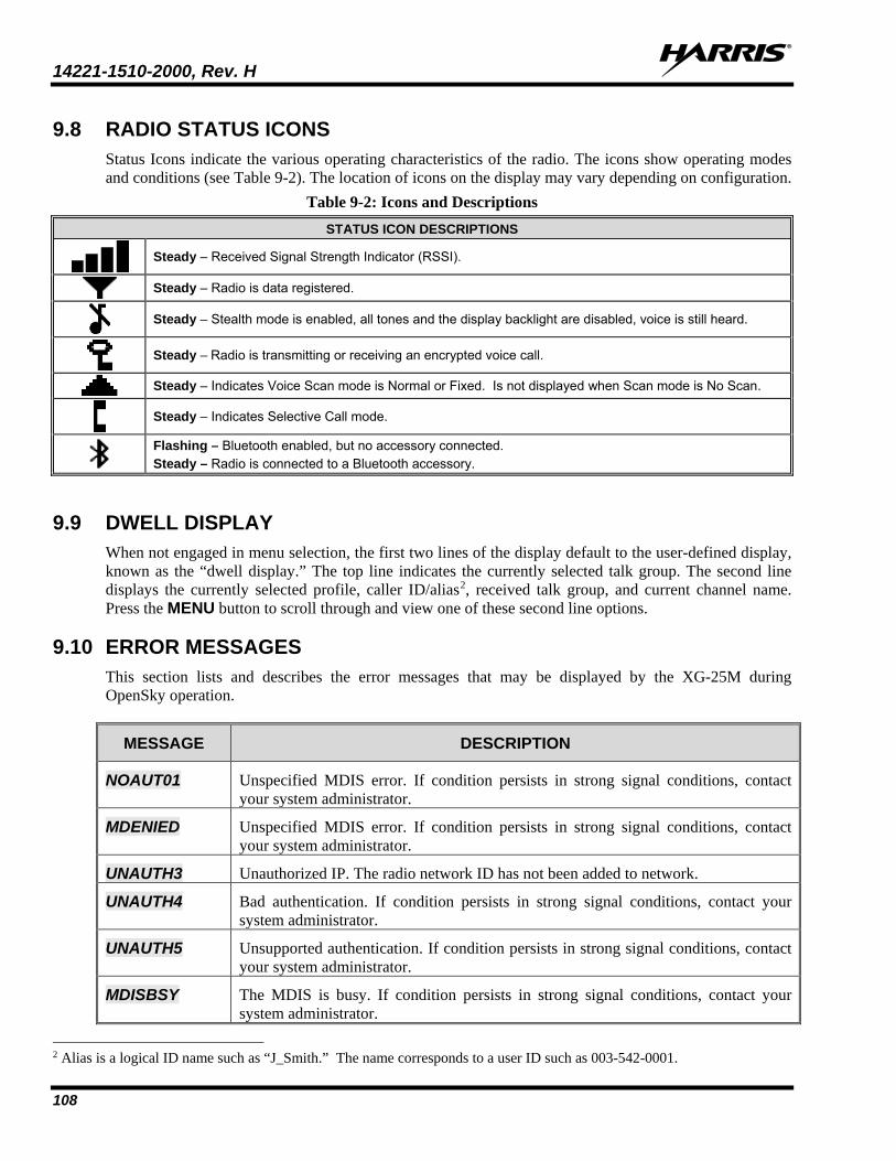
14221-1510-2000, Rev. H
108
9.8 RADIO STATUS ICONS Status Icons indicate the various operating characteristics of the radio. The icons show operating modes and conditions (see Table 9-2). The location of icons on the display may vary depending on configuration.
Table 9-2: Icons and Descriptions STATUS ICON DESCRIPTIONS
Steady – Received Signal Strength Indicator (RSSI).
Steady – Radio is data registered.
Steady – Stealth mode is enabled, all tones and the display backlight are disabled, voice is still heard.
Steady – Radio is transmitting or receiving an encrypted voice call.
Steady – Indicates Voice Scan mode is Normal or Fixed. Is not displayed when Scan mode is No Scan.
Steady – Indicates Selective Call mode.
Flashing – Bluetooth enabled, but no accessory connected. Steady – Radio is connected to a Bluetooth accessory.
9.9 DWELL DISPLAY When not engaged in menu selection, the first two lines of the display default to the user-defined display, known as the “dwell display.” The top line indicates the currently selected talk group. The second line displays the currently selected profile, caller ID/alias2, received talk group, and current channel name. Press the MENU button to scroll through and view one of these second line options.
9.10 ERROR MESSAGES This section lists and describes the error messages that may be displayed by the XG-25M during OpenSky operation.
MESSAGE DESCRIPTION
NOAUT01 Unspecified MDIS error. If condition persists in strong signal conditions, contact your system administrator.
MDENIED Unspecified MDIS error. If condition persists in strong signal conditions, contact your system administrator.
UNAUTH3 Unauthorized IP. The radio network ID has not been added to network.
UNAUTH4 Bad authentication. If condition persists in strong signal conditions, contact your system administrator.
UNAUTH5 Unsupported authentication. If condition persists in strong signal conditions, contact your system administrator.
MDISBSY The MDIS is busy. If condition persists in strong signal conditions, contact your system administrator.
2 Alias is a logical ID name such as “J_Smith.” The name corresponds to a user ID such as 003-542-0001.
14221-1510-2000, Rev. H
109
MESSAGE DESCRIPTION
DUP IP Duplicate IP.
BADIKEY Invalid infrastructure public key sequence number (IPKSN).
BADEKEY Invalid end-system public key sequence number (EPKSN).
UNK MES Unknown mobile end system (MES). If condition persists in strong signal conditions, contact your system administrator.
NOAUT05 MDIS failed mutual authentication. If condition persists in strong signal conditions, contact your system administrator.
BADMDIS MDIS failed mutual authentication. If condition persists in strong signal conditions, contact your system administrator.
MDS BSY MDIS busy – retry.
UNK DOM Unknown home domain. If condition persists in strong signal conditions, contact your system administrator.
KEYSYNC Mismatched key sequence number.
UNK ALG Unknown/unsupported encryption algorithm.
BADSIZE Unsupported MDIS key size.
NOAUT11 MES failed data mutual authentication. If condition persists in strong signal conditions, contact your system administrator.
NOAUT12 No response from MDIS. If condition persists in strong signal conditions, contact your system administrator.
NOREPLY No SME response from MDIS. If condition persists in strong signal conditions, contact your system administrator.
VDENIED Unspecified VNIC error. If condition persists in strong signal conditions, contact your system administrator.
BAD VID Invalid voice user ID. Check User ID. If correct, contact your system administrator.
HOM DWN The Home VNIC is down. Retry. If error continues, contact your system administrator.
SRV BSY The serving VNIC is busy (congested).
MAX USR The maximum users are already registered with the specified user ID. OpenSky allows one User ID to log onto the network using up to three different radios.
NAS BSY The system cannot provision MES because of an administrative process.
NOAUTHM The MES failed voice mutual authentication. If a valid radio displays this error, contact TAC.
NOSUPRT The MES cannot support the required provision. If condition persists in strong signal conditions, contact your system administrator.
NOAUTHV VNIC does not support or failed mutual authentication. If condition persists in strong signal conditions, contact your system administrator.
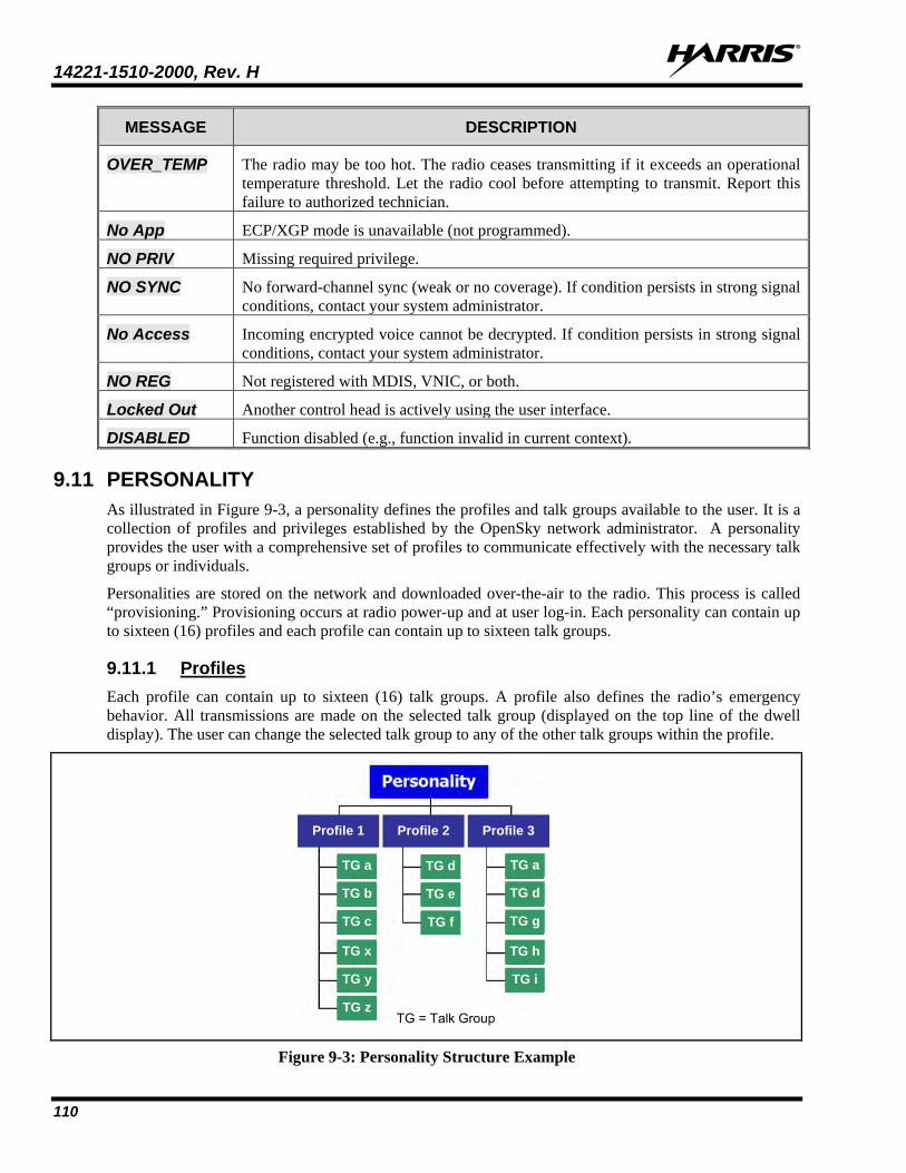
14221-1510-2000, Rev. H
110
MESSAGE DESCRIPTION
OVER_TEMP The radio may be too hot. The radio ceases transmitting if it exceeds an operational temperature threshold. Let the radio cool before attempting to transmit. Report this failure to authorized technician.
No App ECP/XGP mode is unavailable (not programmed).
NO PRIV Missing required privilege.
NO SYNC No forward-channel sync (weak or no coverage). If condition persists in strong signal conditions, contact your system administrator.
No Access Incoming encrypted voice cannot be decrypted. If condition persists in strong signal conditions, contact your system administrator.
NO REG Not registered with MDIS, VNIC, or both.
Locked Out Another control head is actively using the user interface.
DISABLED Function disabled (e.g., function invalid in current context).
9.11 PERSONALITY As illustrated in Figure 9-3, a personality defines the profiles and talk groups available to the user. It is a collection of profiles and privileges established by the OpenSky network administrator. A personality provides the user with a comprehensive set of profiles to communicate effectively with the necessary talk groups or individuals.
Personalities are stored on the network and downloaded over-the-air to the radio. This process is called “provisioning.” Provisioning occurs at radio power-up and at user log-in. Each personality can contain up to sixteen (16) profiles and each profile can contain up to sixteen talk groups.
9.11.1 Profiles Each profile can contain up to sixteen (16) talk groups. A profile also defines the radio’s emergency behavior. All transmissions are made on the selected talk group (displayed on the top line of the dwell display). The user can change the selected talk group to any of the other talk groups within the profile.
Figure 9-3: Personality Structure Example
TG a
TG b
TG c
TG x
TG y
TG z
TG d
TG e
TG f
TG a
TG d
TG g
TG h
TG i
TG = Talk Group
Profile 1 Profile 2 Profile 3
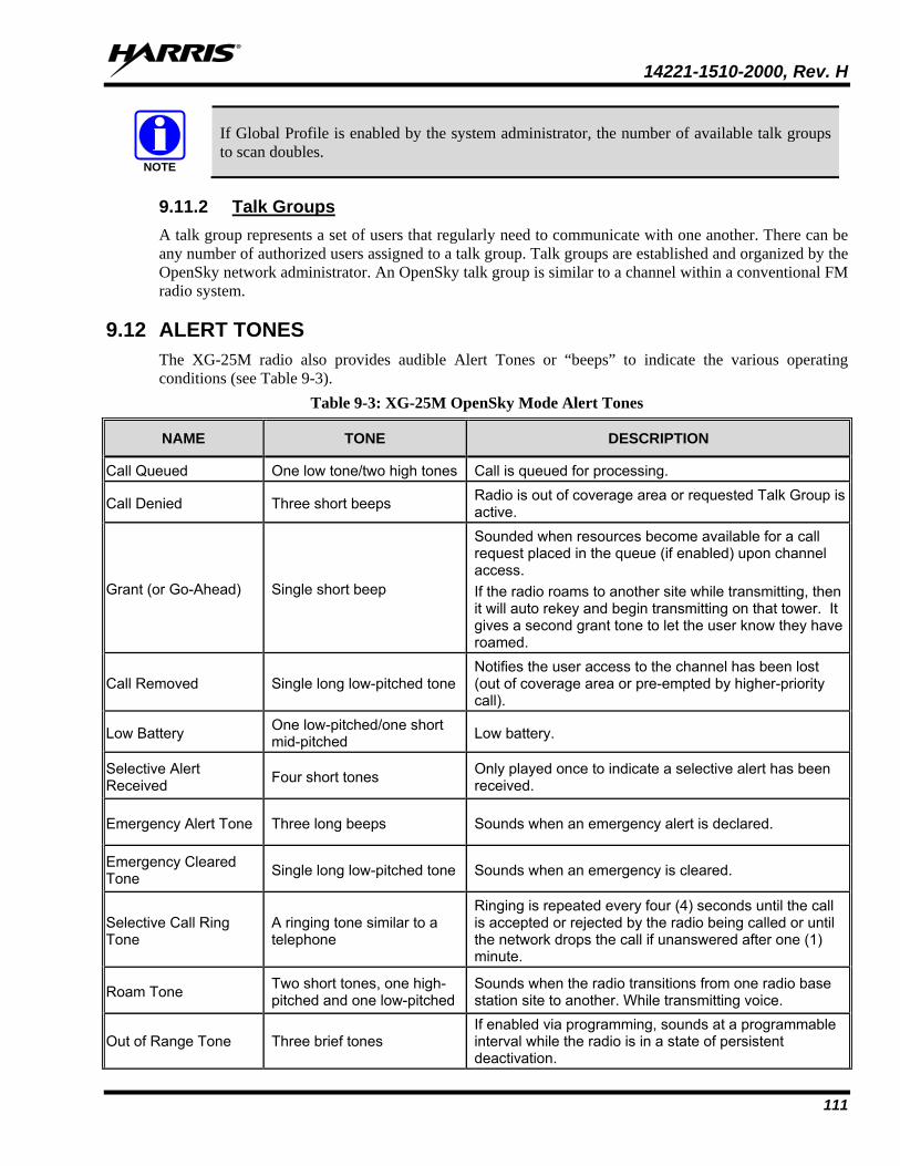
14221-1510-2000, Rev. H
111
If Global Profile is enabled by the system administrator, the number of available talk groups to scan doubles.
9.11.2 Talk Groups A talk group represents a set of users that regularly need to communicate with one another. There can be any number of authorized users assigned to a talk group. Talk groups are established and organized by the OpenSky network administrator. An OpenSky talk group is similar to a channel within a conventional FM radio system.
9.12 ALERT TONES The XG-25M radio also provides audible Alert Tones or “beeps” to indicate the various operating conditions (see Table 9-3).
Table 9-3: XG-25M OpenSky Mode Alert Tones
NAME TONE DESCRIPTION
Call Queued One low tone/two high tones Call is queued for processing.
Call Denied Three short beeps Radio is out of coverage area or requested Talk Group is active.
Grant (or Go-Ahead) Single short beep
Sounded when resources become available for a call request placed in the queue (if enabled) upon channel access. If the radio roams to another site while transmitting, then it will auto rekey and begin transmitting on that tower. It gives a second grant tone to let the user know they have roamed.
Call Removed Single long low-pitched tone Notifies the user access to the channel has been lost (out of coverage area or pre-empted by higher-priority call).
Low Battery One low-pitched/one short mid-pitched Low battery.
Selective Alert Received Four short tones Only played once to indicate a selective alert has been
received.
Emergency Alert Tone Three long beeps Sounds when an emergency alert is declared.
Emergency Cleared Tone Single long low-pitched tone Sounds when an emergency is cleared.
Selective Call Ring Tone
A ringing tone similar to a telephone
Ringing is repeated every four (4) seconds until the call is accepted or rejected by the radio being called or until the network drops the call if unanswered after one (1) minute.
Roam Tone Two short tones, one high-pitched and one low-pitched
Sounds when the radio transitions from one radio base station site to another. While transmitting voice.
Out of Range Tone Three brief tones If enabled via programming, sounds at a programmable interval while the radio is in a state of persistent deactivation.
NOTE
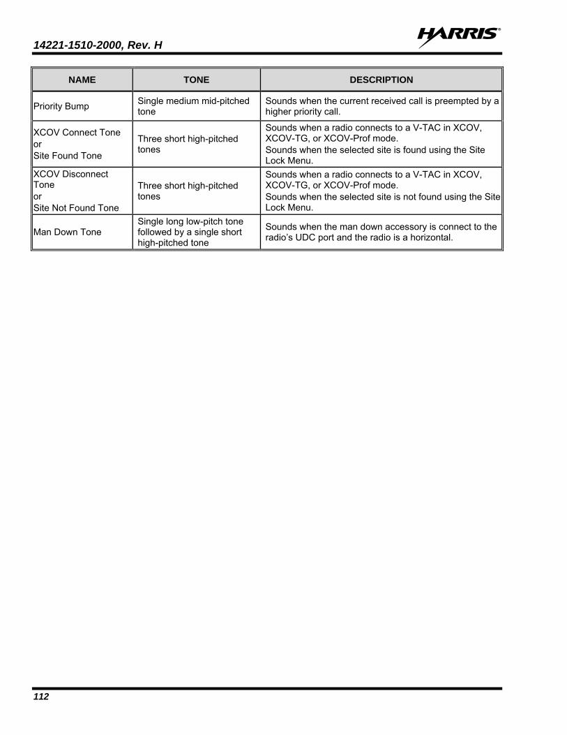
14221-1510-2000, Rev. H
112
NAME TONE DESCRIPTION
Priority Bump Single medium mid-pitched tone
Sounds when the current received call is preempted by a higher priority call.
XCOV Connect Tone or Site Found Tone
Three short high-pitched tones
Sounds when a radio connects to a V-TAC in XCOV, XCOV-TG, or XCOV-Prof mode. Sounds when the selected site is found using the Site Lock Menu.
XCOV Disconnect Tone or Site Not Found Tone
Three short high-pitched tones
Sounds when a radio connects to a V-TAC in XCOV, XCOV-TG, or XCOV-Prof mode. Sounds when the selected site is not found using the Site Lock Menu.
Man Down Tone Single long low-pitch tone followed by a single short high-pitched tone
Sounds when the man down accessory is connect to the radio’s UDC port and the radio is a horizontal.
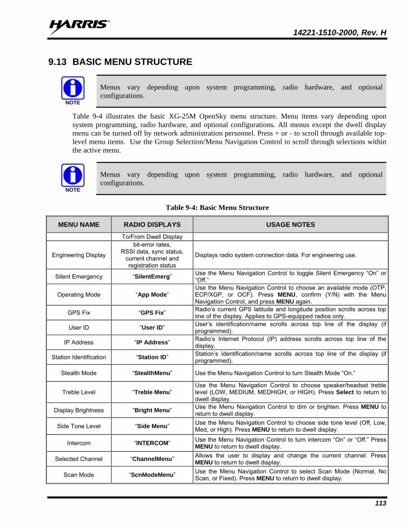
14221-1510-2000, Rev. H
113
9.13 BASIC MENU STRUCTURE
Menus vary depending upon system programming, radio hardware, and optional configurations.
Table 9-4 illustrates the basic XG-25M OpenSky menu structure. Menu items vary depending upon system programming, radio hardware, and optional configurations. All menus except the dwell display menu can be turned off by network administration personnel. Press + or - to scroll through available top-level menu items. Use the Group Selection/Menu Navigation Control to scroll through selections within the active menu.
Menus vary depending upon system programming, radio hardware, and optional configurations.
Table 9-4: Basic Menu Structure
MENU NAME RADIO DISPLAYS USAGE NOTES
To/From Dwell Display
Engineering Display
bit-error rates, RSSI data, sync status,
current channel and registration status
Displays radio system connection data. For engineering use.
Silent Emergency “SilentEmerg” Use the Menu Navigation Control to toggle Silent Emergency “On” or “Off.”
Operating Mode “App Mode” Use the Menu Navigation Control to choose an available mode (OTP, ECP/XGP, or OCF). Press MENU, confirm (Y/N) with the Menu Navigation Control, and press MENU again.
GPS Fix “GPS Fix” Radio’s current GPS latitude and longitude position scrolls across top line of the display. Applies to GPS-equipped radios only.
User ID “User ID” User’s identification/name scrolls across top line of the display (if programmed).
IP Address “IP Address” Radio’s Internet Protocol (IP) address scrolls across top line of the display.
Station Identification “Station ID” Station’s identification/name scrolls across top line of the display (if programmed).
Stealth Mode “StealthMenu” Use the Menu Navigation Control to turn Stealth Mode “On.”
Treble Level “Treble Menu” Use the Menu Navigation Control to choose speaker/headset treble level (LOW, MEDIUM, MEDHIGH, or HIGH). Press Select to return to dwell display.
Display Brightness “Bright Menu” Use the Menu Navigation Control to dim or brighten. Press MENU to return to dwell display.
Side Tone Level “Side Menu” Use the Menu Navigation Control to choose side tone level (Off, Low, Med, or High). Press MENU to return to dwell display.
Intercom “INTERCOM” Use the Menu Navigation Control to turn intercom “On” or “Off.” Press MENU to return to dwell display.
Selected Channel “ChannelMenu” Allows the user to display and change the current channel. Press MENU to return to dwell display.
Scan Mode “ScnModeMenu” Use the Menu Navigation Control to select Scan Mode (Normal, No Scan, or Fixed). Press MENU to return to dwell display.
NOTE
NOTE
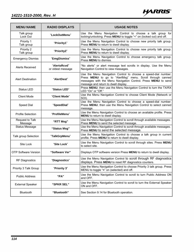
14221-1510-2000, Rev. H
114
MENU NAME RADIO DISPLAYS USAGE NOTES
Talk group Lock Out “LockOutMenu” Use the Menu Navigation Control to choose a talk group for
locking/unlocking. Press MENU to toggle “<” on (locked out) and off.
Priority 1 Talk group “Priority1” Use the Menu Navigation Control to choose new priority talk group.
Press MENU to return to dwell display. Priority 2
Talk group “Priority2” Use the Menu Navigation Control to choose new priority talk group. Press MENU to return to dwell display.
Emergency Dismiss “EmgDismiss” Use the Menu Navigation Control to choose emergency talk group. Press MENU to dismiss.
Alerts Received “AlertsRcvd” or oldest message
“No alerts” or alert message text scrolls in display. Use the Menu Navigation Control to view messages.
Alert Destination “AlertDest” Use the Menu Navigation Control to choose a speed-dial number. Press MENU to go to “AlertMsg” menu. Scroll through canned messages with the Menu Navigation Control. Press MENU to send message and return to dwell display.
Status LED “Status LED” Press MENU, then use the Menu Navigation Control to turn the TX/RX LED “On” or “Off.”
Client Mode “Client Mode” Use the Menu Navigation Control to choose Client Mode (Network or SOI).
Speed Dial “SpeedDial” Use the Menu Navigation Control to choose a speed-dial number. Press MENU, then use the Menu Navigation Control to select canned message.
Profile Selection “ProfileMenu” Use the Menu Navigation Control to choose an available profile. Press MENU to return to dwell display.
Request to Talk Message “RTT Msg” Use the Menu Navigation Control to scroll through available messages.
Press MENU to send the selected message. Status Message “Status Msg” Use the Menu Navigation Control to scroll through available messages.
Press MENU to send the selected message.
Talk group Selection “TalkGrpMenu” Use the Menu Navigation Control to choose a talk group in current profile. Press MENU to return to dwell display.
Site Lock “Site Lock” Use the Menu Navigation Control to scroll through sites. Press MENU to select site.
OTP Software Version “Software Ver” Displays OTP software version Press MENU to return to dwell display.
RF Diagnostics “Diagnostics” Use the Menu Navigation Control to scroll through RF diagnostics displays. Press MENU to reset RF diagnostics counters.
Priority 3 Talk Group “Priority 3” Use the Menu Navigation Control to choose Priority 3 talk group. Press MENU to toggle “<” on (selected) and off.
Public Address “PA” Use the Menu Navigation Control to scroll to turn Public Address ON and OFF.
External Speaker “SPKR SEL” Use the Menu Navigation Control to scroll to turn the External Speaker ON and OFF.
Bluetooth “Bluetooth” See Section 9.14 for Bluetooth operation.
14221-1510-2000, Rev. H
115
9.14 CONNECTING A BLUETOOTH WIRELESS SPEAKER/MICROPHONE The radio can be programmed so a Bluetooth wireless speaker/microphone or another similar type Bluetooth wireless audio device can be used with it. If the radio is programmed as such, use the following procedures as necessary:
9.14.1 Turning Bluetooth On Follow this procedure to turn on the radio’s Bluetooth wireless feature.
1. Press the radio’s + or – buttons until TURN ON Bluetooth is displayed.
2. Press MENU to turn on Bluetooth.
3. The radio displays TURNING ON BLUETOOTH.
4. When complete the (Bluetooth) icon flashes indicating Bluetooth is turned on.
9.14.2 Pairing/Connecting a Bluetooth Wireless Device with the Radio
1. Turn on the Bluetooth wireless device (e.g., wireless speaker/mic) and place it in pairing mode. Consult the device’s operator manual as necessary. Some devices may refer to this mode as “discovery mode.”
Some Bluetooth devices will time-out of their pairing mode after a preset time. Be familiar with the device’s audible and/or visual pairing mode indications, and re-enter pairing mode if this occurs before the radio can be paired with/connected to it.
2. Press the radio’s + or – buttons until SEL TO ENTER Bluetooth is displayed.
If SEL TO ENTER Bluetooth does not appear the radio is not programmed for Bluetooth wireless operations. The Bluetooth menu would need to be enabled.
3. Press MENU.
4. Press the + or – buttons until ADD DEVICE displayed.
5. Press MENU.
6. The radio then displays SEARCHING as it begins searching for nearby Bluetooth devices that it can pair/connect with. During the search, the current number of the found Bluetooth devices is displayed and the (Bluetooth) icon blinks in the display.
The (Bluetooth) icon blinks in the display when the radio’s Bluetooth function is on but the radio is not actively connected to a Bluetooth device.
7. Wait for the search to complete. When done, the radio displays SELECT and the name of the first pairable device located during its search.
NOTE
NOTE
14221-1510-2000, Rev. H
116
8. Press the + or – buttons until the name of the desired wireless Bluetooth device for connection to appears.
9. Press MENU.
10. The radio displays PAIRING.
11. After several seconds, the pairing completes. This is indicated when radio displays PAIRING COMPLETE.
12. The (Bluetooth) icon stops blinking and remains on.
13. Also note the device’s audible and/or visual indication per the successful pairing/connection, such as a blue light and/or beeps.
If the name of the desired Bluetooth wireless device was not listed, first verify the device is still in pairing mode (aka., discovery mode), then use the SEARCH AGAIN function, or repeat this procedure from step 4.
If the selected Bluetooth wireless device cannot be successfully paired, PAIRING FAILED displays, followed by ADD DEVICE. In this case, the device has most likely either exited its pairing mode (aka., discovery mode) since the radio’s search feature found it or it has been turned off (either manually or automatically). Correct as necessary and then use the ADD DEVICE function to perform another search.
9.14.3 Basic Bluetooth Wireless Device Operations After successful pairing/connection, radio receive audio and alert tones are routed to the speaker/earpiece of the Bluetooth wireless device instead of to the radio’s (internal/external) speaker. The radio’s previously active (internal/external) speaker remains muted. Volume control adjustments for the wireless device are made at the device, not at the radio’s control head.
The PTT switch of the standard/wired microphone connected to the control head remains active when a Bluetooth device is actively paired with the radio. The radio can be keyed from this PTT switch; however, transmit audio will be sourced from the microphone of the Bluetooth wireless device.
After being paired with a Bluetooth wireless device, if the radio or the device is powered off and then back on, pairing will be automatically re-established a short time after power-up. This assumes the device is within wireless range of the radio.
Refer to the Bluetooth wireless device’s operator manual for additional information about using it with the radio.
NOTE
14221-1510-2000, Rev. H
117
9.14.4 Deleting a Bluetooth Wireless Device To prevent the previously-connected device from re-connecting to the radio, follow this procedure.
1. Press the radio’s + or – buttons until SEL TO ENTER Bluetooth is displayed.
2. Press MENU.
3. Press the radio’s + or – buttons until DELETE appears, followed by the device’s name.
4. Press the MENU button to delete the Bluetooth device.
9.14.5 Turning Bluetooth Off Follow this procedure to turn off the radio’s Bluetooth wireless feature. When turned off, a currently connected device will be disconnected. Also, no Bluetooth devices can pair/connect with the radio:
1. Press the radio’s + or – buttons until SEL TO ENTER Bluetooth is displayed.
2. Press MENU.
3. Press the radio’s + or – buttons until TURN OFF BLUETOOTH is displayed.
4. Press MENU.
5. The radio immediately disconnects the previously connected Bluetooth device, and its (Bluetooth) icon disappears.
9.15 CHANGE THE ACTIVE PROFILE The radio can store up to sixteen (16) standard profiles, one of which is the currently active profile. To change the currently active profile:
1. Scroll through the menu until “ProfileMenu” is displayed.
2. Use the Menu Navigation Control to scroll through the list of available profiles.
3. Profile becomes active when selected for longer than two (2) seconds, when the MENU is pressed, or when the menu is changed.
9.16 ENABLE/DISABLE VOLUME SIDE TONE The Volume Side Tone sounds when adjusting the volume control.
To enable or disable this tone:
1. Power off the radio.
2. Press and hold the B button while turning the radio on.
14221-1510-2000, Rev. H
118
9.17 CHECK OR CHANGE THE SELECTED TALK GROUP Each profile stored in the radio can have up to sixteen (16) talk groups. One talk group within the currently active profile is set as the “selected talk group.” For the radio user, the selected talk group is typically the focus of most voice transmissions and receptions. There are two ways to change the selected talk group:
First Method:
1. Scroll through the menu until “TalkGrpMenu” appears on the bottom line of the display. The currently selected talk group appears in the top line of the display.
2. Use the Menu Navigation Control to scroll through the available list of talk groups in the active profile. This list is determined by the OpenSky network administrator.
Second Method:
From the dwell display, use the talk group selection knob or the Menu Navigation Control to scroll through the available list of talk groups in the active profile.
9.18 ADJUST DISPLAY AND BUTTON BACKLIGHT BRIGHTNESS
1. Scroll through the menu until “Bright Menu” appears.
2. Use the Menu Navigation Control to increase or decrease brightness. Display and button backlight brightness immediately dims or brightens.
9.19 STEALTH MODE For some users, it is important to be able to turn off the radio’s display lights, button backlighting, volume and side tones, but not radio traffic. For example, in covert operations, lights and sounds could inadvertently expose an otherwise unobservable radio user. For this purpose, the radio has a Stealth feature that disables the radio display light, indicator light, and audible side tones.
When Stealth Mode is on, the radio continues to scan the programmed list of talk groups and the user can key-up on the selected talk group. All buttons are disabled except for PTT, Emergency, and MENU. Since the screen is blank, the user cannot see the result of other button presses.
9.19.1 Enable Stealth Mode
1. Scroll through the menu until “StealthMenu” appears.
2. Use the Menu Navigation Control to enable Stealth Mode.
9.19.2 Disable Stealth Mode To turn Stealth Mode off, press the MENU button on the radio’s front panel.
14221-1510-2000, Rev. H
119
9.20 ADJUST SIDE TONE AUDIO LEVEL The radio sounds confirming tones called “side tones” when its buttons are pressed. Most users find this audible confirmation helpful when navigating the menus. Side tone audio level can be adjusted or turned completely off using the “Side Menu.”
For covert operations, it may be necessary to turn off side tones. For safety’s sake, turning off the radio during covert operations is not recommended.
To temporarily disable the side tones that could expose the user’s presence and position, use the menu buttons to access the “Side Menu” and select “Off” from the menu choices.
If the radio is operating properly but side tones are not heard when the menu buttons are pressed, the side tones are probably turned off. To turn them back on, access the “Side Tone” menu and select a setting other than “Off.”
Use the following procedure to set side tone level:
1. Scroll through the menu until the “Side Menu” appears in the bottom line of the display.
2. Use the Menu Navigation Control to change to the desired level (Off, Low, Medium, and High). To turn side tones completely off, use the “Off” setting.
9.21 CHANGE OPERATING MODE
1. Scroll through the menu until “App Mode” appears in the bottom line of the display.
2. Use the Menu Navigation Control to choose an available mode. Press MENU and confirm (Y/N) with the Menu Navigation Control and press MENU again.
Or
Preset button C can be configured via programming to reboot the radio into a particular application mode.
9.22 RECEIVE AND TRANSMIT VOICE CALLS As soon as the radio completes the startup/login/provision/self-test sequence and registers on the OpenSky network, voice calls from talk groups in the active profile are audible.
9.22.1 Receive a Voice Call
The Alias/User ID/Talk Group name are only displayed if that dwell display option is selected using the MENU button. For example, if the user sets the dwell display option to profile, the profile continues to be displayed when a call is received.
No action is required to receive a voice call. The display responds to incoming voice calls as follows:
• When the dwell display is set to received talk group, the scan mode is Normal or Fixed:
If the received talk group matches the selected talk group, then the alias (if available) or user ID of the incoming caller is displayed.
If the received talk group does not match the selected talk group, then the received talk group name is displayed
NOTE
14221-1510-2000, Rev. H
120
• When the dwell display is set to received talk group and the Scan Mode is None, the radio only receives voice on its selected talk group. When the call is received, the alias (if available) or the user ID of the incoming caller is displayed.
• When the dwell display is not set to received talk group, then there is no display indication of an incoming call.
A radio receiving a System All Call displays “All Call” instead of the alias. A radio not transmitting on a talk group in emergency status drops all other calls to scan into an All Call.
Refer to Section 9.26 for detailed information on talk group scanning. Refer to Section 9.30 for detailed information regarding sending and receiving encrypted calls.
9.22.2 Transmit a Voice Call Transmit a voice call as follows:
1. Turn the radio on.
2. Select the talk group on which you want to transmit.
3. Press and hold the Push-to-Talk (PTT) button on the hand-held microphone, pause for a moment, and then speak normally. For maximum clarity, hold the microphone approximately 2 inches from the mouth and do not shout or whisper into it. If the call is queued by the network, wait for the grant tone to sound before speaking.
4. Release the PTT button when finished speaking.
Refer to Section 9.30 for detailed information regarding sending and receiving encrypted calls.
9.23 ADJUST AUDIO TREBLE LEVEL The tone of received signals can be adjusted using the radio’s “Treble Menu” as follows:
1. Scroll through the menu until “Treble Menu” appears. The radio’s current treble level setting indicates in the top line of the display. There are four levels available: low, medium, medium-high, and high.
2. Use the Menu Navigation Control to increase or decrease treble level.
3. Press the MENU button or wait a few seconds to return to the Dwell Display.
9.24 INTERCOM MODE The optional intercom mode gives users at multiple control heads connected to the same radio the ability to communicate with each other without transmitting over-the-air. Turn intercom mode on and off using the “INTERCOM” menu as follows:
1. Scroll through the available menu items until “INTERCOM” appears in the display.
2. Use the Menu Navigation Control to toggle between “On” and “Off.”
NOTE
14221-1510-2000, Rev. H
121
When intercom mode is turned on:
• Incoming voice calls override intercom communications for the duration of the voice call. The radio and associated control heads remain in intercom mode and intercom communications resume when the voice call ends.
• “TG: INTERCOM” appears in the control head’s display when talking on the intercom. This indicates microphone audio is not sent out on the selected talk group; rather, it remains localized between the radio control positions (i.e., the control heads connected to the mobile radio).
• If a call exists on the currently selected talk group when a PTT button is pressed at one of the control heads, “TG: in use” appears in the display to indicate intercom mic audio cannot preempt the call on the talk group.
A user at a radio with only one control head/front panel can turn intercom mode on. In this case, pressing the microphone’s PTT button does NOT send microphone audio anywhere.
9.25 TALK GROUP LOCK OUT There are two ways of focusing voice communications by suppressing calls from talk groups in the currently active profile:
1. No Scan: By turning scan off (selecting “No Scan” via the “ScnModeMenu”), only the selected talk group is audible.
2. Lock Out: By locking out selected talk groups, the “chatter” of the locked out talk groups cannot be heard. This focuses the user’s scanning resources to calls only on desired talk groups.
Talk group lock out is a scan-related feature. With lock out, one or more talk groups in the active profile can be temporarily disabled from being scanned. Calls are not received on locked-out talk groups. Lock out settings are not retained between profile changes or when the radio is power cycled.
Lock out is a listening (receive) function and only blocks received calls on locked out talk groups. Lock out does not affect transmit capability. The above methods do not apply to recent emergency lock outs.
Only talk groups in the active profile can be locked out, since they are the only talk groups whose voice calls can be heard on the radio.
P1, P2, and P3 talk groups cannot be locked out.
The default emergency and emergency-capable talk groups can be locked out if they are NOT in an emergency state. If a talk group is locked out and is subsequently changed to the currently selected talk group, it is automatically unlocked by the radio so the user can hear calls on the talk group. The radio may be configured so all talk groups are automatically locked out by default. In this case, they must be manually unlocked, if desired.
NOTE
NOTE
14221-1510-2000, Rev. H
122
9.25.1 Lock Out a Talk Group
1. Scroll through the menu until “LockOutMenu” appears in the bottom line of the display. The name of a talk group in the currently active profile appears in the top line.
2. Use to scroll through the list of talk groups, if any, until the desired talk group for lock out appears in the top line of the display.
3. Press the MENU button to lockout the displayed talk group. A less than symbol (<) appears next to the talk group’s name.
4. Repeat steps 2 and 3, as needed, to lock out additional talk groups.
The dwell display re-appears a few seconds after button presses end.
While scrolling through talk groups in the active profile, the only talk groups that appear in the “LockOutMenu” are those in the active profile.
9.25.2 Unlock a Talk Group
1. Scroll through the menu until “LockOutMenu” appears in the bottom line of the display. The name of a talk group in the currently active profile appears in the top line.
2. Use the Menu Navigation Control to scroll through the list of talk groups, if any, until the talk group desired for unlocking appears in the top line of the display. A less-than symbol (“<”) appears next to the name of a talk group that is currently locked out.
3. Press the MENU button to unlock the talk group. The less-than symbol (“<”) next to the name of the talk group disappears. The dwell display appears as soon as the radio acknowledges the selection.
• Changing the active profile removes any lock outs you have made.
• Turning off the radio removes any lock outs you have made.
9.26 SCANNING Three scanning modes are available for the radio, but only one can be active at any time. Changing the scanning mode changes the way the radio scans voice calls for all of profiles in the radio personality, no matter which profile is or becomes active.
As described in Table 9-5, the choice of scanning mode changes the span of communications with all the talk groups in the radio’s profiles, but does not affect interaction with the talk groups.
NOTE
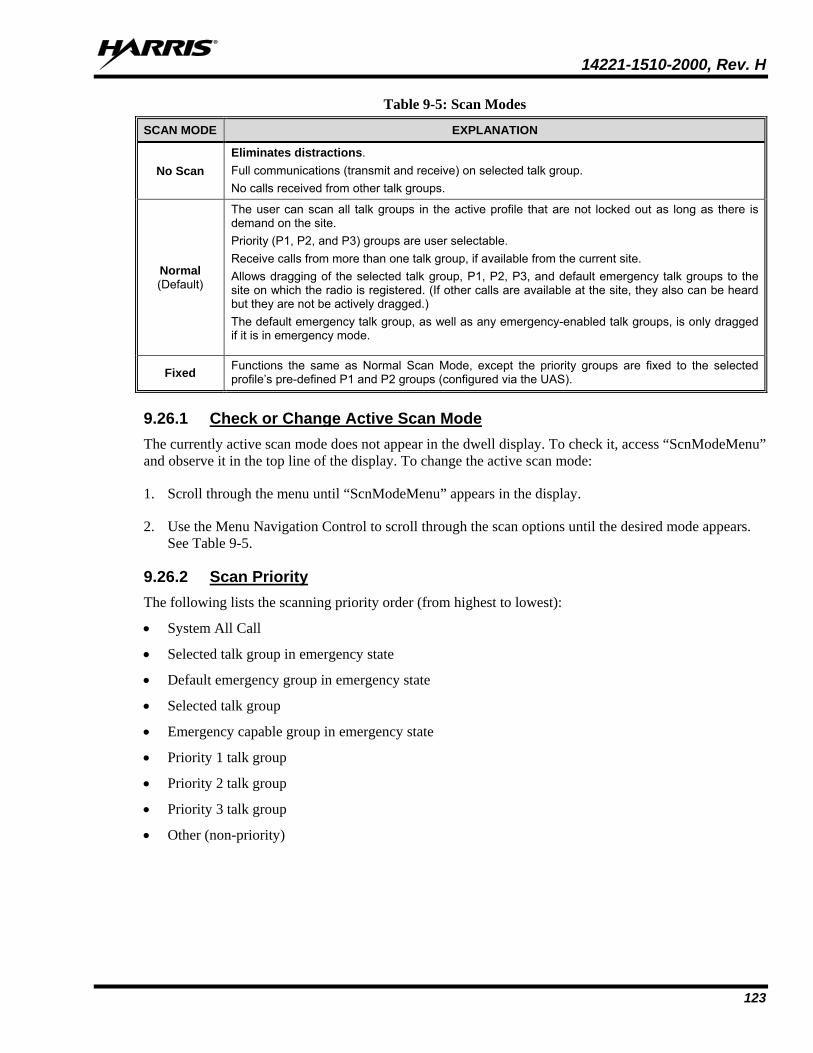
14221-1510-2000, Rev. H
123
Table 9-5: Scan Modes
SCAN MODE EXPLANATION
No Scan Eliminates distractions. Full communications (transmit and receive) on selected talk group. No calls received from other talk groups.
Normal (Default)
The user can scan all talk groups in the active profile that are not locked out as long as there is demand on the site. Priority (P1, P2, and P3) groups are user selectable. Receive calls from more than one talk group, if available from the current site. Allows dragging of the selected talk group, P1, P2, P3, and default emergency talk groups to the site on which the radio is registered. (If other calls are available at the site, they also can be heard but they are not be actively dragged.) The default emergency talk group, as well as any emergency-enabled talk groups, is only dragged if it is in emergency mode.
Fixed Functions the same as Normal Scan Mode, except the priority groups are fixed to the selected profile’s pre-defined P1 and P2 groups (configured via the UAS).
9.26.1 Check or Change Active Scan Mode The currently active scan mode does not appear in the dwell display. To check it, access “ScnModeMenu” and observe it in the top line of the display. To change the active scan mode:
1. Scroll through the menu until “ScnModeMenu” appears in the display.
2. Use the Menu Navigation Control to scroll through the scan options until the desired mode appears. See Table 9-5.
9.26.2 Scan Priority The following lists the scanning priority order (from highest to lowest):
• System All Call
• Selected talk group in emergency state
• Default emergency group in emergency state
• Selected talk group
• Emergency capable group in emergency state
• Priority 1 talk group
• Priority 2 talk group
• Priority 3 talk group
• Other (non-priority)
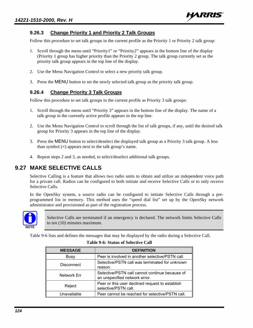
14221-1510-2000, Rev. H
124
9.26.3 Change Priority 1 and Priority 2 Talk Groups Follow this procedure to set talk groups in the current profile as the Priority 1 or Priority 2 talk group:
1. Scroll through the menu until “Priority1” or “Priority2” appears in the bottom line of the display (Priority 1 group has higher priority than the Priority 2 group. The talk group currently set as the priority talk group appears in the top line of the display.
2. Use the Menu Navigation Control to select a new priority talk group.
3. Press the MENU button to set the newly selected talk group as the priority talk group.
9.26.4 Change Priority 3 Talk Groups Follow this procedure to set talk groups in the current profile as Priority 3 talk groups:
1. Scroll through the menu until “Priority 3” appears in the bottom line of the display. The name of a talk group in the currently active profile appears in the top line.
2. Use the Menu Navigation Control to scroll through the list of talk groups, if any, until the desired talk group for Priority 3 appears in the top line of the display.
3. Press the MENU button to select/deselect the displayed talk group as a Priority 3 talk group. A less than symbol (<) appears next to the talk group’s name.
4. Repeat steps 2 and 3, as needed, to select/deselect additional talk groups.
9.27 MAKE SELECTIVE CALLS Selective Calling is a feature that allows two radio units to obtain and utilize an independent voice path for a private call. Radios can be configured to both initiate and receive Selective Calls or to only receive Selective Calls.
In the OpenSky system, a source radio can be configured to initiate Selective Calls through a pre-programmed list in memory. This method uses the “speed dial list” set up by the OpenSky network administrator and provisioned as part of the registration process.
Selective Calls are terminated if an emergency is declared. The network limits Selective Calls to ten (10) minutes maximum.
Table 9-6 lists and defines the messages that may be displayed by the radio during a Selective Call. Table 9-6: Status of Selective Call
MESSAGE DEFINITION Busy Peer is involved in another selective/PSTN call.
Disconnect Selective/PSTN call was terminated for unknown reason.
Network Err Selective/PSTN call cannot continue because of an unspecified network error.
Reject Peer or this user declined request to establish selective/PSTN call.
Unavailable Peer cannot be reached for selective/PSTN call.
NOTE
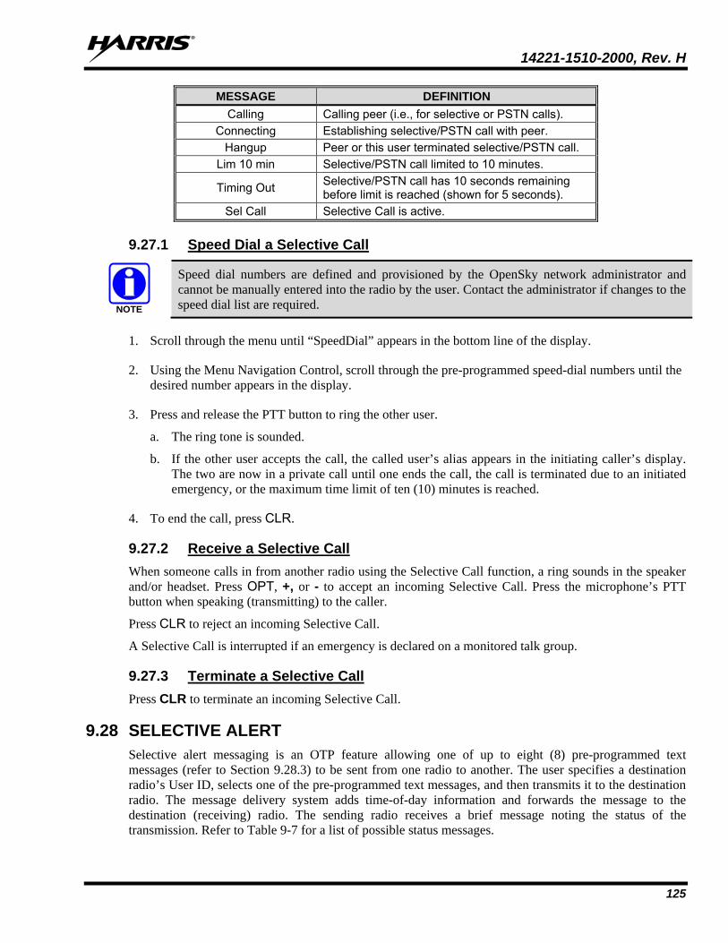
14221-1510-2000, Rev. H
125
MESSAGE DEFINITION Calling Calling peer (i.e., for selective or PSTN calls).
Connecting Establishing selective/PSTN call with peer. Hangup Peer or this user terminated selective/PSTN call.
Lim 10 min Selective/PSTN call limited to 10 minutes.
Timing Out Selective/PSTN call has 10 seconds remaining before limit is reached (shown for 5 seconds).
Sel Call Selective Call is active.
9.27.1 Speed Dial a Selective Call
Speed dial numbers are defined and provisioned by the OpenSky network administrator and cannot be manually entered into the radio by the user. Contact the administrator if changes to the speed dial list are required.
1. Scroll through the menu until “SpeedDial” appears in the bottom line of the display.
2. Using the Menu Navigation Control, scroll through the pre-programmed speed-dial numbers until the desired number appears in the display.
3. Press and release the PTT button to ring the other user.
a. The ring tone is sounded.
b. If the other user accepts the call, the called user’s alias appears in the initiating caller’s display. The two are now in a private call until one ends the call, the call is terminated due to an initiated emergency, or the maximum time limit of ten (10) minutes is reached.
4. To end the call, press CLR.
9.27.2 Receive a Selective Call When someone calls in from another radio using the Selective Call function, a ring sounds in the speaker and/or headset. Press OPT, +, or - to accept an incoming Selective Call. Press the microphone’s PTT button when speaking (transmitting) to the caller.
Press CLR to reject an incoming Selective Call.
A Selective Call is interrupted if an emergency is declared on a monitored talk group.
9.27.3 Terminate a Selective Call Press CLR to terminate an incoming Selective Call.
9.28 SELECTIVE ALERT Selective alert messaging is an OTP feature allowing one of up to eight (8) pre-programmed text messages (refer to Section 9.28.3) to be sent from one radio to another. The user specifies a destination radio’s User ID, selects one of the pre-programmed text messages, and then transmits it to the destination radio. The message delivery system adds time-of-day information and forwards the message to the destination (receiving) radio. The sending radio receives a brief message noting the status of the transmission. Refer to Table 9-7 for a list of possible status messages.
NOTE
14221-1510-2000, Rev. H
126
The first few characters of a message are part of the message text entered when the message is programmed. This programming is performed by the system or network administration personnel.
Messages successfully received by the destination radio are stored until deleted or until the radio is power cycled.
9.28.1 Send Selective Alert Messages Select the destination radio’s User ID from the menu.
1. Scroll through the menu until “AlertDest” (Alert Destination) appears in the bottom line of the display. The current speed dial number scrolls on the top line.
2. Use the Menu Navigation Control to change to a different speed-dial number.
3. When the desired speed-dial number appears, press the MENU button to activate the selection.
4. Scroll through the message list using the Menu Navigation Control. The next available message in the list is displayed. Pause between each arrow button press to observe the entire message as it scrolls across the top line of the display.
5. To select and send the displayed message, press the MENU button.
6. The status of the sent message is momentarily displayed (Table 9-7).
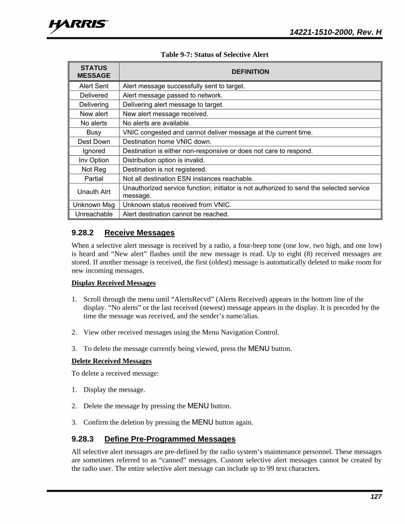
14221-1510-2000, Rev. H
127
Table 9-7: Status of Selective Alert
STATUS MESSAGE DEFINITION
Alert Sent Alert message successfully sent to target. Delivered Alert message passed to network. Delivering Delivering alert message to target. New alert New alert message received. No alerts No alerts are available.
Busy VNIC congested and cannot deliver message at the current time. Dest Down Destination home VNIC down.
Ignored Destination is either non-responsive or does not care to respond. Inv Option Distribution option is invalid. Not Reg Destination is not registered. Partial Not all destination ESN instances reachable.
Unauth Alrt Unauthorized service function; initiator is not authorized to send the selected service message.
Unknown Msg Unknown status received from VNIC. Unreachable Alert destination cannot be reached.
9.28.2 Receive Messages When a selective alert message is received by a radio, a four-beep tone (one low, two high, and one low) is heard and “New alert” flashes until the new message is read. Up to eight (8) received messages are stored. If another message is received, the first (oldest) message is automatically deleted to make room for new incoming messages.
Display Received Messages
1. Scroll through the menu until “AlertsRecvd” (Alerts Received) appears in the bottom line of the display. “No alerts” or the last received (newest) message appears in the display. It is preceded by the time the message was received, and the sender’s name/alias.
2. View other received messages using the Menu Navigation Control.
3. To delete the message currently being viewed, press the MENU button.
Delete Received Messages
To delete a received message:
1. Display the message.
2. Delete the message by pressing the MENU button.
3. Confirm the deletion by pressing the MENU button again.
9.28.3 Define Pre-Programmed Messages All selective alert messages are pre-defined by the radio system’s maintenance personnel. These messages are sometimes referred to as “canned” messages. Custom selective alert messages cannot be created by the radio user. The entire selective alert message can include up to 99 text characters.
14221-1510-2000, Rev. H
128
9.29 EMERGENCY COMMUNICATIONS The XG-25M mobile radio can transmit both emergency voice calls and emergency alerts over the entire network. OpenSky handles emergency calls and alerts with the highest priority.
For critical voice communications, an emergency call can be raised on the default talk group or the currently selected talk group by “declaring” an emergency on the talk group. The exact talk group is determined by the currently active profile. After successfully declaring an emergency on a talk group, the declaring radio’s microphone remains “hot” for a predetermined amount of time. In other words, the radio transmits audio for a period of time even when the microphone’s PTT button is not pressed. An emergency talk group is provided greater priority and infinite hang-time by the radio system’s infrastructure. Hang-time is the maximum duration of quiet time between transmissions on the talk group before the infrastructure assets are automatically taken away. Because an emergency call is handled on a talk group, it is received by all radios and consoles monitoring the talk group.
An emergency alert is a data message sent by the radio to the MIS console (or any console capable of receiving it). It identifies the radio declaring the emergency, and the radio’s location (if the radio is equipped with a GPS receiver). Voice audio is not automatically transmitted during the emergency if the administrator configures the radio for alert notification only.
9.29.1 Declare an Emergency Call or Alert
1. Press the red emergency button on the radio to enter emergency mode. The emergency is raised after the emergency raise delay [default is one (1) second].
• If the active profile of the unit initiating the emergency is configured for Emergency Alert, the emergency alert signal is sent to registered alert servers, such as the dispatcher console.
• If the active profile of the unit initiating the emergency is configured for Emergency Call, the talkgroup is placed into emergency status notifying other radios and the emergency alert signal is sent to the dispatcher console.
• If the emergency behavior of the active profile is Current, the active, selected voice group becomes the default emergency voice group.
• If the emergency behavior of the active profile is Default, the radio moves to the default emergency voice group of the profile and this talk group becomes the select talk group.
2. The display alternates between “Emergency” and whatever option is selected for the 2nd line of the dwell display.
If the attempt is unsuccessful, “E-PEND” flashes periodically and a retry is queued for 10 seconds. If unsuccessful because of lost sync, retry occurs immediately upon reacquiring sync. On each retry attempt, radio temporarily displays “E-RETRY.” This process repeats until the emergency is successfully declared.
9.29.2 Silent Emergency When this feature is enabled and an emergency call or alert is declared by pressing the emergency button, the radio does not play a tone and displays an abbreviated emergency message (default is EBA). This feature is enabled or disabled via programming or via the menu.
If the Silent Emergency feature is enabled or disabled via programming, the setting survives power cycle. Enable/Disable selection via the menu does NOT survive power cycle and the enable/disable state reverts to the programmed setting at power up. NOTE
14221-1510-2000, Rev. H
129
9.29.3 Clear an Emergency Call or Alert
Check with the system administrator to ensure that the radio is programmed to allow an emergency to be cleared.
If enabled via programming, clear an emergency by:
1. Pressing and holding the CLR button and simultaneously pressing the emergency button.
2. After the Emergency Cleared Tone sounds, release both buttons.
If the radio is in Stealth Mode, clearing the emergency takes the radio out of Stealth Mode.
9.29.4 Receive an Emergency Call Upon receiving an emergency call declared by another radio:
• An emergency tone sounds in the radio’s speaker/headset (three short high-pitched beeps).
• “EMERGENCY” flashes in the display if the radio is not in stealth mode. When receiving voice in an active emergency, the flashing “EMERGENCY” is inhibited so that the alias of the sender can be seen.
• On receiving radios with the emergency talk group selected, the alias of the sending party is displayed for 5 seconds during the open-mic period, then the word “Emergency” flashes on the second line of the display and continues until the emergency state ends.
• If scan mode is set to “No Scan” and the emergency was declared on the selected talk group, audio on the emergency talk group is heard in the speaker/headset. See page 122 for additional information on “No Scan” operation.
• If scan mode is set to “No Scan” and the emergency was declared on a talk group other than the selected talk group, the emergency talk group (identified by an “*”) must be selected before audio on it is heard in the speaker/headset.
• If scan mode is set to “Normal” and the emergency was declared on the selected talk group, the selected/emergency talk group’s name remains in the top line of the display. Audio on the emergency talk group is heard in the speaker/headset.
• If scan mode is set to “Normal” and the emergency was declared on a talk group other than the selected talk group, the emergency talk group’s name appears in the bottom line of the display. Audio on the emergency talk group is heard in the speaker/headset.
• The declaring radio's alias appears in the bottom line of the display when the emergency talk group is selected.
• An emergency call can be dismissed as described in the following section.
A radio declaring an emergency on a talk group has a “hot” mic time period of typically ten (10) seconds just after it declares the emergency. This time period may be adjusted by system or network administration personnel on a per radio basis.
NOTE
NOTE
NOTE
14221-1510-2000, Rev. H
130
9.29.5 Dismiss an Emergency Call
An emergency is dismissed for a configurable amount of time only (default = 5 minutes).
To ignore an emergency call declared by another radio user:
1. Scroll through the menu until “EmgDismiss” appears in the display.
2. Press the Menu Navigation Control until the talk group in the emergency state appears, as indicated by an asterisk (*) following the talk group’s name.
3. Press the MENU button.
The emergency dismiss timer is cleared when the emergency is cleared.
9.30 ENCRYPTION In the OpenSky network, both data and voice use a 128-bit or 256-bit key encryption standard published by the Federal Information Processing Service (FIPS), called Advanced Encryption Standard (AES). AES is approved by the U.S. Department of Commerce for encryption of classified materials.
When encryption is enabled on the network, data is encrypted from the MDIS to the Mobile End System (MES) (e.g., XG-25M mobile radio). This form of encryption provides air-link security.
A network administrator selects the talk group to be encrypted at the interface to the UAS. Once the talk groups have been selected and identified as secure, credentials for key generation are generated automatically by the system and provisioned to authorized users. This process requires that authorized users login to the network and be authenticated. Encryption keys require no manual handling and are never sent “in the clear” over any network interface or air-link.
If a user is engaged in a call on a talk group encrypted at the network administrator level, “Secure Call” appears in the bottom line of the dwell display if the user is logged in to that talk group.
If a secure call is in progress elsewhere and the user has not logged in, the bottom of the dwell display alternates between “No Access” and the alias of the radio that is currently engaged in the secure call.
9.31 PRESET BUTTONS The front panel contains three buttons labeled A, B, and C. By holding one of these buttons down for approximately three (3) seconds, the following current information is saved to the function of that button:
• Selected Priority 1, Priority 2, and Priority 3 talk groups
• Selected profile
• Selected talk group
• Lock outs
• Scan mode
• Intercom mode
NOTE
NOTE
14221-1510-2000, Rev. H
131
Presets are saved and restored to/from non-volatile memory. Changing the User ID (login in as a different user) clears the presets since they are stored on a per-user basis. Changing control heads does not recall presets for the previous control head.
Preset button C can be configured via programming to reboot the radio into a particular application mode, toggle the external speaker OFF/ON, toggle the Public Address OFF/ONN or toggles the Selective Call Alert. Contact your system administrator to determine if this feature is enabled in your radio.
9.32 STATUS MESSAGES If enabled via programming, the radio can transmit a pre-programmed status message.
1. Scroll through the menu until “Status Msg” appears and press MENU. If no messages have been configured, “No Messages” is displayed.
2. Scroll through the available messages using the Menu Navigation Control. The configured Status message is displayed on the 1st line of the display.
3. Press the MENU button to send the currently selected message. If no messages have been configured, no message is sent and an error tone sounds.
Press CLR to cancel status message selection.
9.33 REQUEST TO TALK (RTT) MESSAGES If enabled via programming, the RTT message feature allows you to send either a short service message to the VNIC. Only one RTT message can be programmed into the radio.
1. Scroll through the menu until “RTT Msg” appears and press MENU. If no message has been configured, “No Messages” is displayed.
2. Use the Menu Navigation Control to select message. The configured RTT message is displayed on the 1st line of the display.
3. Press the MENU button to send the currently selected message. If no message has been configured, no message is sent and an error tone sounds.
Press CLR to cancel RTT message selection.
9.34 GPS COORDINATES The radio’s current latitude and longitude coordinates may be displayed using the “GPS” menu. The following procedure assumes a GPS antenna is connected to the radio and it is receiving adequate signals from GPS satellites:
1. Scroll through the menu until the “GPS” menu appears in the bottom line of the display.
2. Current GPS coordinate latitude and longitude data continuously scrolls in the top line of the display in a degrees:minutes:seconds format.
If the internal GPS receiver’s data is expired (30 minutes or more) or unavailable, the radio uses the serving base station’s coordinates [GPS (Site) is displayed]. The GPS Menu also indicates if the data is aged (2 minutes or more) [GPS (Aged) is displayed].
NOTE
NOTE
14221-1510-2000, Rev. H
132
9.35 SCENE-OF-INCIDENT MODE The Scene-of-Incident mode (SOI) is user-selectable. The SOI mode provides a local repeater function (V-TAC) with no network connection.
When operating in the SOI mode, the radio is disconnected from the OpenSky network. Therefore, communications with radios and dispatch personnel on the network is not possible.
Enter SOI Mode Manually Entering the Channel:
1. Scroll through the menu until the Client Mode menu appears.
2. Using the Menu Navigation Control, scroll until SOI is displayed.
3. Press the MENU button to confirm mode selection.
4. Using the Menu Navigation Control, scroll until “Manual Select Chan” is displayed and press MENU.
5. Using the Menu Navigation Control, scroll to edit the right-most digit and press MENU to advance to the next digit. Repeat until the desired channel is entered.
6. The radio then prompts the user to edit the band. Use the Menu Navigation Control to edit the number assigned to the frequency band and press MENU to confirm and enter the SOI mode.
Use the Client Mode menu to return to normal operation (Network Mode). The personality and profile in use at the time the radio entered SOI mode is restored.
Enter SOI Mode Selecting Pre-Programmed Channel:
1. Scroll through the menu until the Client Mode menu appears.
2. Using the Menu Navigation Control, scroll until SOI is displayed.
3. Press MENU to confirm mode selection.
4. Using the Menu Navigation Control, scroll through a list of pre-programmed channels.
5. Press MENU to confirm channel and enter SOI mode.
Use the Client Mode menu to return to normal operation (Network Mode). The personality and profile in use at the time the radio entered SOI mode is restored.
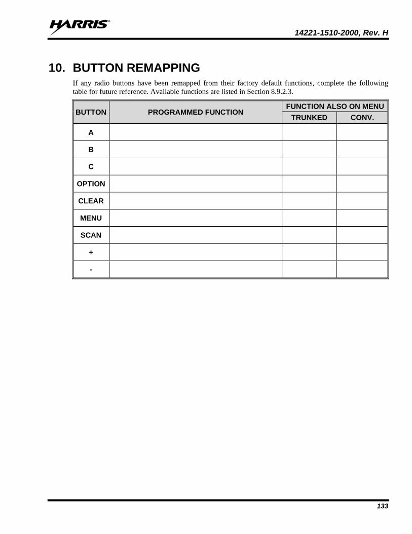
14221-1510-2000, Rev. H
133
10. BUTTON REMAPPING If any radio buttons have been remapped from their factory default functions, complete the following table for future reference. Available functions are listed in Section 8.9.2.3.
BUTTON PROGRAMMED FUNCTION FUNCTION ALSO ON MENU
TRUNKED CONV.
A
B
C
OPTION
CLEAR
MENU
SCAN
+
-
14221-1510-2000, Rev. H
134
11. CUSTOMER SERVICE 11.1 CUSTOMER CARE
If any part of the system equipment is damaged on arrival, contact the shipper to conduct an inspection and prepare a damage report. Save the shipping container and all packing materials until the inspection and the damage report are completed. In addition, contact the Customer Care center to make arrangements for replacement equipment. Do not return any part of the shipment until you receive detailed instructions from a Harris representative.
Contact the Customer Care center at http://www.pspc.harris.com/CustomerService or:
North America: Phone Number: 1-800-368-3277 Fax Number: 1-321-409-4393 E-mail: [email protected]
International: Phone Number: 1-434-455-6403 Fax Number: 1-321-409-4394 E-mail: [email protected]
11.2 TECHNICAL ASSISTANCE The Technical Assistance Center’s (TAC) resources are available to help with overall system operation, maintenance, upgrades and product support. TAC is the point of contact when answers are needed to technical questions.
Product specialists with detailed knowledge of product operation, maintenance and repair provide technical support via a toll-free (in North America) telephone number. Support is also available through mail, fax and e-mail.
For more information about technical assistance services, contact your sales representative, or call the Technical Assistance Center at: North America: 1-800-528-7711 International: 1-434-385-2400 Fax: 1-434-455-6712 E-mail: [email protected]
11.3 WARRANTY Please register this product within 10 days of purchase. Registration validates the warranty coverage, and enables Harris to contact you in case of any safety notifications issued for this product.
Registration can be made on-line at the Customer Care center webpage:
http://www.pspc.harris.com/Service/Customerservice.aspx.
While on the webpage, please review the applicable battery and/or product warranty literature.
14221-1510-2000, Rev. H
135
APPENDIX A - CONFIGURING ENCRYPTION A.1 ENCYRPTION KEYS
Refer to the following documentation for advanced programming and setup instructions:
• Harris OTAR Overview Manual - MM-008069-001
• Network Key Manager Installation and Configuration Manual - MM-008070-001
• Harris UAS Key Management Application Manual - MM-008068-001
• Harris Key Manager Key Admin Overview and Operation Manual - MM1000019423
• Harris Key Manager Key Loader Overview and Operation Manual - MM1000019424
• Motorola® Key Variable Loader (KVL) Device User's Guide
A.1.1 Create Keys Using Harris Key Admin Harris Key Admin is part of the Harris Key Manager and is used by the Crypto Officer (CO). The CO creates a Master Set of keys from which a Distribution Set is produced. Using the Key Admin software, the CO can save keys into Distribution key files for technicians to use in radios.
1. Select Start Programs Harris Key Manager Harris Key Admin.
2. Select New Master Set, Open, or Import from Security Device. Refer to the Key Admin online help for more information on creating keys.
3. When finished, create a Distribution Key File. A Distribution Key File is used with the Key Loader to load key sets into the radio and cannot be edited. Refer to the Key Admin online help for more information on creating the Distribution Key File.
A.1.2 Load Encryption Keys A.1.2.1 Load UKEKS with Key Loader and RPM (for OTAR-Enabled Systems) UKEKs are loaded into Harris OTAR radios using the Key Loader application. Key Loader is a part of Key Manager.
To load encryption keys:
1. Obtain the UKEK file and Storage Location Number (SLN) Binding Report information from the Crypto Officer (CO).
Both AES and DES UKEKs can be contained within the same UKEK file.
2. If not already on, power-up the PC that has RPM and the Key Loader applications installed on it, and start Windows®.
3. Connect the radio to the PC using a serial cable (14002-0143-01).
4. Enter into the Harris Keyload Mode (HKL).
a. Press the radio’s MENU button.
NOTE
14221-1510-2000, Rev. H
136
b. Scroll through the menu to select the KEYLOAD option and press the MENU button to activate.
c. Scroll through and select the HKL option and press the MENU button. The radio can now accept keys from the Harris Keyloader.
5. Load the UKEK file from the Crypto Officer onto the PC.
6. Run the RPM application and setup the radio’s Mission Plan according the SLN Binding Report information.
7. Setup the talk groups and the SLN mappings (Talk Group ID to SLN). This includes mapping SLNs to the “System” keys (PSTN, All Call, etc.).
8. Select Options P25 OTAR Options and set the following:
a. The OTAR Message Number Period (MNP) as defined by the System Administrator.
b. The radio’s Individual RSI (from the SLN Bindings Report).
c. The KMF’s RSI (from the SLN Bindings Report).
9. Program the Mission Plan to the radio.
10. Run the Key Loader application.
11. Open the UKEK file loaded in step 5.
12. Select the Target Device type and click the Load button.
13. The Key Loader reads the target device’s identifying information, retrieves a UKEK of the proper algorithm type from the UKEK file, and downloads the UKEK to the target device at the proper SLN and keyset with the proper key ID.
14. Click the Finish button to exit the Key Loader application. New UKEKs have are loaded and the radio is now ready to accept TEKs via OTAR with the trunked radio network.
A.1.2.2 Load Keys Using Harris Key Loader Harris Key Loader is part of Harris Key Manager and can be used by the Crypto Officer or Technician to load the keys into the radio.
Refer to the Harris Key Loader online help if additional information is required when performing this procedure.
1. Connect the radio to the PC using a serial cable.
2. Power on the radio, if not already.
3. Select Start Programs Harris Key Manager Harris Key Loader.
4. At the Key Loader Welcome screen, click Next.
5. Select Load a Distribution Set into one or more devices.
6. Click Next.
7. Browse to the Key File and enter the password.
14221-1510-2000, Rev. H
137
8. Click Next to validate the password and continue. If the password is incorrect, the screen will display an error message.
9. Select communication port from the drop-down and click Next.
10. Select the serial port that you have connected to the radio.
11. Enter into Harris Keyload Mode (HKL).
a. Press the radio’s MENU button.
b. Scroll through the menu to select the KEYLOAD option and press the MENU button to activate.
c. Scroll through and select the HKL option and press the MENU button. The radio can now accept keys from the Harris Keyloader.
12. Select Radio from the drop-down and click Load.
13. Click Finish.
A.1.2.3 Power on the Motorola KVL Device
1. Connect KVL Device to the radio using cable 14002-0143-10.
Once the KVL Device is connected, a keyset is established whether the keys are loaded or not. You will need to zeroize to bring the radio to a fully zeroized state.
2. Press the radio’s MENU button.
3. Scroll through the menu to select the KEYLOAD option and press the MENU button to activate.
4. Scroll through and select the KVL option and press the MENU button. The radio can now accept keys from the KVL Device.
A.1.2.4 Load Keys Using Motorola KVL Device Type 3 Digital Encryption Standard Output Feedback (DES-OFB) and Advanced Encryption Standard, 256-bit (AES-256), encryption methods are supported. The Type 3 Encryption keys are loaded via a Motorola Device using Telecommunications Industry Association (TIA)/Project 25 (P25) key fill device protocol. Make sure that valid keys have been created and stored in the KVL Device before proceeding.
A.1.3 Protected Keys The Protected Keys feature transfers P25 Voice Keys, from Harris Key Loader to the radio, that have been wrapped (AES) or encrypted (DES) with Key Protection Keys (KPKs). KPKs are nothing more than unprotected Key Encryption Keys (KEKs). The KPKs need to be loaded into the radio before the Protected Keys are loaded. Once loaded into the radio, the KPKs will be used to unwrap (AES) or decrypt (DES) the Protected Keys.
The radio must be placed into the key loading mode (see Section A.1.2.2) in order to accept the KPKs and P25 Voice Keys.
NOTE
About Harris Corporation Harris Corporation is a leading technology innovator that creates mission-critical solutions that connect, inform and protect the world. The company’s advanced technology provides information and insight to customers operating in demanding environments from ocean to orbit and everywhere in between. Harris has approximately $8 billion in annual revenue and supports customers in 125 countries through four customer-focused business segments: Communication Systems, Space and Intelligence Systems, Electronic Systems, and Critical Networks.
FLORIDA NEW YORK VIRGINIA BRAZIL UNITED KINGDOM UAE SINGAPORE