Embed Size (px)
Citation preview

Radio Frequency Systems Basic Parts
Last Update 2012.03.27
1.4.0
Copyright 2005-2012 Kenneth M. Chipps Ph.D. www.chipps.com
1

The Basic Parts
• There are just five basic parts in a radio frequency based communication system– Antenna– Amplifier– Filter– Mixer– Source
Copyright 2005-2012 Kenneth M. Chipps Ph.D. www.chipps.com
2

The Basic Parts
• These five parts are then put together to do one of two basic functions– Transmit– Receive
• The name of the resulting device is a radio
Copyright 2005-2012 Kenneth M. Chipps Ph.D. www.chipps.com
3
A Radio
• The radio may also go by many other names based on marketing considerations or its specific role in the wireless network
• A radio is used to send and receive a signal that flows through the air as a series of electromagnetic waves
• Radios can take on many different forms, as such it is not always easy to identify them
Copyright 2005-2012 Kenneth M. Chipps Ph.D. www.chipps.com
4

The Transmitter
• When transmitting or receiving the goal is to produce a perfect sine wave, of the exact size required, at only one frequency
• A block diagram of the basic parts looks like this
• For a transmitter
Copyright 2005-2012 Kenneth M. Chipps Ph.D. www.chipps.com
5

Transmitter Block Diagram
Copyright 2005-2012 Kenneth M. Chipps Ph.D. www.chipps.com
6

The Receiver
• A block diagram of the basic parts looks like this
• For a receiver
Copyright 2005-2012 Kenneth M. Chipps Ph.D. www.chipps.com
7

Receiver Block Diagram
Copyright 2005-2012 Kenneth M. Chipps Ph.D. www.chipps.com
8

The Basic Parts
• The main job of the manufacturers of these basic parts is to attempt to make them– Smaller– Lighter– More energy efficient– Lower in cost
• Now on to some details on each of these parts
Copyright 2005-2012 Kenneth M. Chipps Ph.D. www.chipps.com
9

What is an Antenna
• Every radio frequency wireless system must have an antenna
• You may not see it• You may not recognize it, if you do see it• But it must be there somewhere
Copyright 2005-2012 Kenneth M. Chipps Ph.D. www.chipps.com
10

What is an Antenna
• The antenna does only one thing, it converts electrical signals coming from a conductor into airborne waves or it converts airborne waves into electrical signals to be sent down a conductor
• Being a resonant device it operates efficiently over a narrow frequency band
Copyright 2005-2012 Kenneth M. Chipps Ph.D. www.chipps.com
11

How an Antenna Works
• The real way an antenna does its work is somewhat complex
• But for this level of discussion lets say it this way
• An antenna begins to radiate energy, in the form of radio frequency waves, whenever the length of the antenna becomes close to the wavelength of the signal
Copyright 2005-2012 Kenneth M. Chipps Ph.D. www.chipps.com
12

How an Antenna Works
• When an alternating electric current flows through a conductor, electric and magnetic fields are created around the conductor
• If the length of the conductor is very short compared to a wavelength, the electric and magnetic fields will generally fade out within one or two wavelengths
Copyright 2005-2012 Kenneth M. Chipps Ph.D. www.chipps.com
13

How an Antenna Works
• But as the conductor is lengthened, the intensity of the fields around it grow bigger
• As such, an ever increasing amount of energy escapes into space
Copyright 2005-2012 Kenneth M. Chipps Ph.D. www.chipps.com
14

Why Are Antennas So Short
• It seems in the real world that antennas are always shorter than basic theory would suggest they must be
• This is because when the length of the wire approaches one-half a wavelength at the frequency of the applied alternating current, most of the energy will escape as electromagnetic radiation
Copyright 2005-2012 Kenneth M. Chipps Ph.D. www.chipps.com
15

Why Are Antennas So Short
• So an antenna starts work early• Further, the ground itself is a good
conductor for medium and low frequencies and acts as a large mirror for the radiated energy
• The ground reflects a large amount of energy that is radiated downward from an antenna mounted over it
Copyright 2005-2012 Kenneth M. Chipps Ph.D. www.chipps.com
16

Why Are Antennas So Short
• Using this characteristic of the ground, an antenna only a quarter-wavelength long can be made into the equivalent of a half-wavelength antenna
• All of this means that a quarter-wavelength antenna standing vertically, with its lower end connected electrically to the ground acts just like a half-wave antenna
Copyright 2005-2012 Kenneth M. Chipps Ph.D. www.chipps.com
17

Why Are Antennas So Short
• The ground takes the place of the missing quarter-wavelength
• The reflections supply that part of the radiated energy that normally would be supplied by the lower half of an ungrounded half-wavelength antenna
Copyright 2005-2012 Kenneth M. Chipps Ph.D. www.chipps.com
18

Why Are Antennas So Short
• At the low and medium frequencies, the ground acts as a good conductor
• At the higher frequencies, artificial grounds constructed of large metal surfaces can be used to achieve this effect
• Another factor is that the antenna length of a half-wave dipole is somewhat less than a half-wavelength due to end effect
Copyright 2005-2012 Kenneth M. Chipps Ph.D. www.chipps.com
19

Why Are Antennas So Short
• Lastly, the speed of propagation in coaxial cable is slower than in air, so the wavelength in the cable is shorter
Copyright 2005-2012 Kenneth M. Chipps Ph.D. www.chipps.com
20

Antenna Radiation Pattern
• When selecting an antenna the width of the area to be covered and the distance of each link must be considered
• These considerations will then determine the type of antenna to use based on each antenna’s signal pattern
• Every antenna has a pattern to the signal• This pattern applies to both sending and
receiving
Copyright 2005-2012 Kenneth M. Chipps Ph.D. www.chipps.com
21

Antenna Radiation Pattern
• By convention the radiation line used to draw this pattern is drawn wherever the power radiating out drops to one half the power at the antenna surface
• For example, for a dipole antenna
Copyright 2005-2012 Kenneth M. Chipps Ph.D. www.chipps.com
22

Antenna Radiation Pattern
Copyright 2005-2012 Kenneth M. Chipps Ph.D. www.chipps.com
23

Antenna Radiation Pattern
• As opposed to a directional antenna
Copyright 2005-2012 Kenneth M. Chipps Ph.D. www.chipps.com
24

Antenna Radiation Pattern
Copyright 2005-2012 Kenneth M. Chipps Ph.D. www.chipps.com
25

Antenna Radiation Pattern
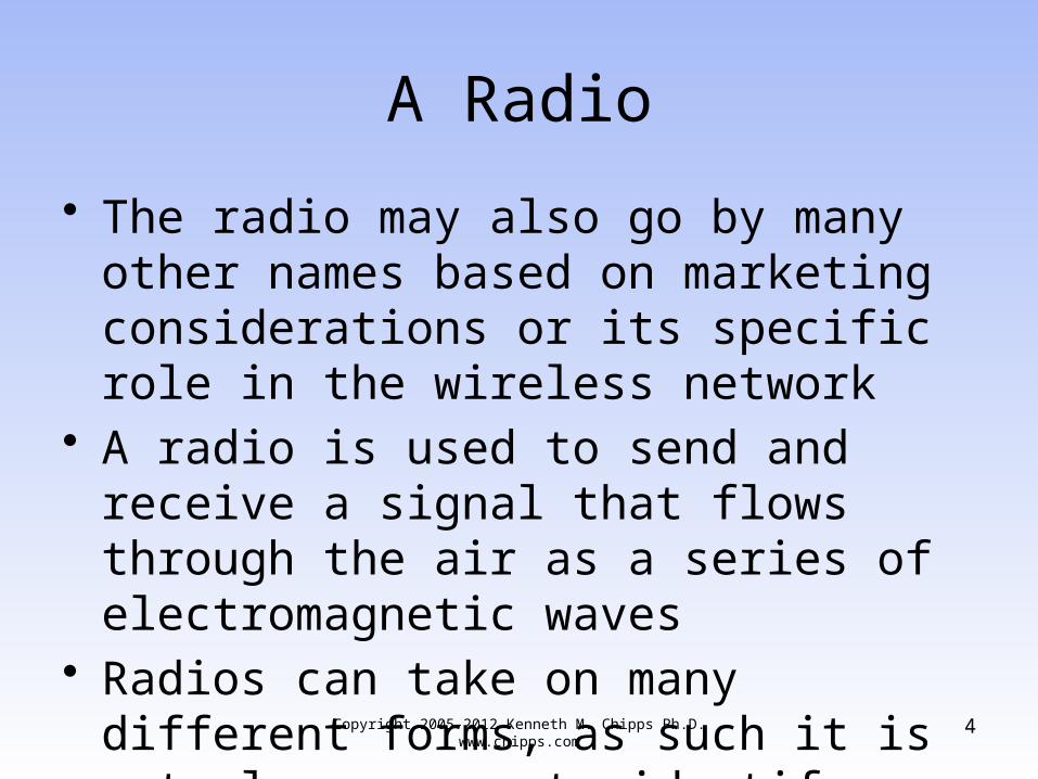
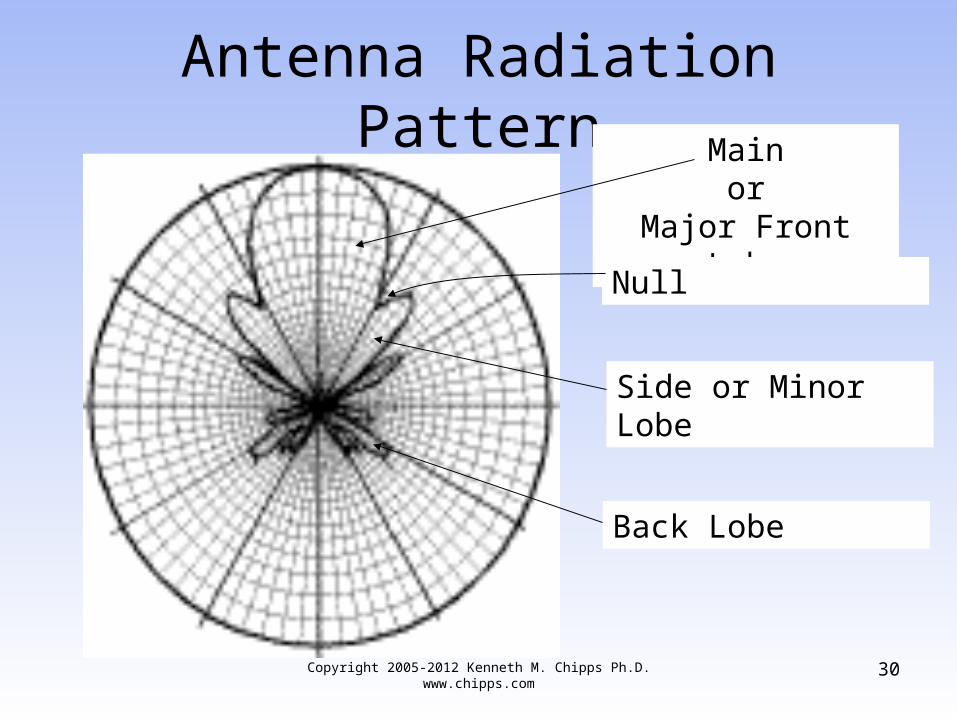
• Note in the diagram above that the radiation pattern does not have an even outline
• In that there is a large main lobe, which is desired, and one or more side lobes, which are undesirable
• These side lobes are also called the minor lobes
Copyright 2005-2012 Kenneth M. Chipps Ph.D. www.chipps.com
26

Antenna Radiation Pattern
• Antennas also have a front to back ratio that is measured in dBs
• The forward gain is the peak gain on the main lobe of the antenna
• The rear gain is measured as either the gain at exactly 180 degrees from the main lobe, or from 90 degrees to 270 degrees from the main lobe
Copyright 2005-2012 Kenneth M. Chipps Ph.D. www.chipps.com
27

Antenna Radiation Pattern
• Using the wider sector is the better way to measure this
• These back lobes are also undesirable• A front to back ratio of 10-15 dB is
considered fair to poor, 15-20 dB is good, 20-30 dB is very good, and above 30 dB is excellent
Copyright 2005-2012 Kenneth M. Chipps Ph.D. www.chipps.com
28

Antenna Radiation Pattern
• The regions in between the main and minor lobes are areas of weak signals called nulls
Copyright 2005-2012 Kenneth M. Chipps Ph.D. www.chipps.com
29
Antenna Radiation Pattern
Copyright 2005-2012 Kenneth M. Chipps Ph.D. www.chipps.com
30
Mainor
Major Front Lobe
Side or Minor Lobe
Null
Back Lobe

Antenna Radiation Pattern
• The pattern provided by the manufacturer can be a rectangular grid or the more popular polar coordinate system just shown
• The plotting scales used range from linear to linear logarithmic to modified logarithmic
• The linear logarithmic and modified logarithmic are the ones most commonly used
Copyright 2005-2012 Kenneth M. Chipps Ph.D. www.chipps.com
31

Antenna Radiation Pattern
• These scales show the side and back lobes as well as the main lobe
• For antennas in the frequencies of interest here these patterns are for the far field of the antenna
• The far field region is the area in which wave propagation occurs
• This field starts basically 10 wavelengths from the antenna
Copyright 2005-2012 Kenneth M. Chipps Ph.D. www.chipps.com
32

Antenna Radiation Pattern
• The radiation pattern of an antenna is adjusted in most cases by adding reflectors and directors
• The reflector adds gain to the antenna, in relation to the isotropic antenna, by redirecting the signal
• The director then concentrates the beam into an even tighter pattern
Copyright 2005-2012 Kenneth M. Chipps Ph.D. www.chipps.com
33

Lab
• Find Radiation Patterns
Copyright 2005-2012 Kenneth M. Chipps Ph.D. www.chipps.com
34

Reflector
• In general the directivity of the antenna is changed by adding a reflector behind the main antenna transmitting element
• There are several types of reflectors– Corner reflector– Trough reflector– Panel reflector
Copyright 2005-2012 Kenneth M. Chipps Ph.D. www.chipps.com
35

Corner Reflector Style
Copyright 2005-2012 Kenneth M. Chipps Ph.D. www.chipps.com
36

Trough Reflector Style
Copyright 2005-2012 Kenneth M. Chipps Ph.D. www.chipps.com
37

Panel Reflector Style
Copyright 2005-2012 Kenneth M. Chipps Ph.D. www.chipps.com
38

Reflector
• The reflector is about 5 percent longer than the driven element
• The driven element being the basic antenna
• It is placed parallel to the driven element about ¼ quarter wavelength from it
• There is no electrical connection between these two elements
Copyright 2005-2012 Kenneth M. Chipps Ph.D. www.chipps.com
39

Reflector
• The reflector works because the radio waves leave the driven element, then encounter the reflector
• Since the reflector is longer, both physically and electrically, than the driven element the signal is bounced back toward the antenna element itself
Copyright 2005-2012 Kenneth M. Chipps Ph.D. www.chipps.com
40

Reflector
• These reflected waves then join up with the radiated waves to increase the signal that leaves the antenna
• This stronger signal is sent off in a direction opposite to the location of the reflector
Copyright 2005-2012 Kenneth M. Chipps Ph.D. www.chipps.com
41

Reflector
Copyright 2005-2012 Kenneth M. Chipps Ph.D. www.chipps.com
42
Reflector
Driven Element
Director
• For even more directivity a director can be added to the antenna as well
• The director is an antenna element that is 5 percent shorter than the driven element
• The director is placed parallel and ¼ wavelength in front of the driven element
• There is no electrical connection between these elements
Copyright 2005-2012 Kenneth M. Chipps Ph.D. www.chipps.com
43

Director
• The effect of the director, being shorter than the driven element, is to draw the radio waves to it
• This serves to force the waves into a tighter beam
Copyright 2005-2012 Kenneth M. Chipps Ph.D. www.chipps.com
44

Director
Copyright 2005-2012 Kenneth M. Chipps Ph.D. www.chipps.com
45
Driven Element
Director

Passive or Active Antenna
• An antenna can be a passive device or it can be an active device
• In other words, it either has a power supply attached or it does not
• The passive antenna is just a shape, a piece of metal configured into whatever form is required for the specific application
Copyright 2005-2012 Kenneth M. Chipps Ph.D. www.chipps.com
46

Passive and Active Antenna
• The active antenna is just a shape, a piece of metal configured into whatever form is required for the specific application and with a power supply
Copyright 2005-2012 Kenneth M. Chipps Ph.D. www.chipps.com
47

Active Antenna
• The power supply for an active antenna can be a separate device or more likely the power comes in on the same connection as the RF signal
Copyright 2005-2012 Kenneth M. Chipps Ph.D. www.chipps.com
48
Antenna Size and Shape
• The size and shape of an antenna depends on three things– Frequency– Direction– Power
• In general the lower the frequency the larger the antenna
Copyright 2005-2012 Kenneth M. Chipps Ph.D. www.chipps.com
49
Antenna Size and Shape
• So even though we would get better coverage if cell phone cells were the size of AM broadcast areas, the antenna would be somewhat too large for the average size pocket
Copyright 2005-2012 Kenneth M. Chipps Ph.D. www.chipps.com
50

Antenna Gain• All antennas have gain• However this may or may not be real gain• Real gain is that produced by applying a
power supply directly to the antenna• Yet even passive antennas have gain• How is this possible• It is so because antenna gain is measured
in relation to a theoretical antenna called an isotropic antenna
Copyright 2005-2012 Kenneth M. Chipps Ph.D. www.chipps.com
51

Antenna Gain
• There is no such real thing as an isotropic antenna
• If there was it would show a radiation pattern where the signal radiated out from a single point in space equally in all directions
• In other words a radiation ball• As in
Copyright 2005-2012 Kenneth M. Chipps Ph.D. www.chipps.com
52

Antenna Gain
• Go get a balloon
Copyright 2005-2012 Kenneth M. Chipps Ph.D. www.chipps.com
53

Antenna Gain
Copyright 2005-2012 Kenneth M. Chipps Ph.D. www.chipps.com
54

Antenna Gain• Well not exactly a basketball, but you get
the idea• The energy then goes equally in all
directions• Since an isotropic radiator cannot be
produced, any real antenna will have some gain when compared to it
• So antenna gain is a combination of directional gain and power gain
Copyright 2005-2012 Kenneth M. Chipps Ph.D. www.chipps.com
55

Antenna Gain
• There is always directional gain, in relation to the isotropic radiator’s radiation pattern
• There is also power gain, if the antenna is an active antenna
• This directional gain is expressed in relation to the isotropic radiator by using decibels
• In this case a special decibel, the dBi
Copyright 2005-2012 Kenneth M. Chipps Ph.D. www.chipps.com
56

Antenna Gain
• A second measure that is important to antenna gain is the power coming out of the antenna
• The output power of the antenna is named the EIRP – Equivalent Isotropically Radiated Power as discussed below
Copyright 2005-2012 Kenneth M. Chipps Ph.D. www.chipps.com
57

Lab
• Find Gain of Antennas
Copyright 2005-2012 Kenneth M. Chipps Ph.D. www.chipps.com
58

Beamwidth
• Another aspect to keep in mind when setting up an antenna is the beamwidth it produces
• The beamwidth has two aspects– Vertical– Horizontal
• The vertical beamwidth is perpendicular to the Earth’s surface and the horizontal beamwidth is parallel to the Earth’s surface
Copyright 2005-2012 Kenneth M. Chipps Ph.D. www.chipps.com
59
Beamwidth
• Antenna design determines beamwidth• Common ranges for different types of
antennas are
Copyright 2005-2012 Kenneth M. Chipps Ph.D. www.chipps.com
60

BeamwidthAntenna Type Vertical Horizontal
Omni 7 - 80 360
Patch or Panel 6 – 90 30 – 180
Yagi 14 – 64 30 – 78
Parabolic Dish 4 – 21 4 - 25
Copyright 2005-2012 Kenneth M. Chipps Ph.D. www.chipps.com
61

Lab
• Find Beamwidth of Antennas
Copyright 2005-2012 Kenneth M. Chipps Ph.D. www.chipps.com
62

The 6 dB Rule
• A useful rule for estimating range of an antenna is the 6 dB rule
• In this relationship a 6 dB increase in EIRP doubles the range, whereas a 6 dB decrease in EIRP halves the range
• For example
Copyright 2005-2012 Kenneth M. Chipps Ph.D. www.chipps.com
63

The 6 dB RuleDistance in Meters Loss in dB
100 80.23
200 86.25
500 94.21
1,000 100.23
2,000 106.25
5,000 114.21
10,000 120.23
Copyright 2005-2012 Kenneth M. Chipps Ph.D. www.chipps.com
64

Antenna Shapes
• Antennas come in all sorts of shapes and sizes
• However, in general there are two basic shapes– One dimensional– Two dimensional
Copyright 2005-2012 Kenneth M. Chipps Ph.D. www.chipps.com
65
One Dimensional Antennas
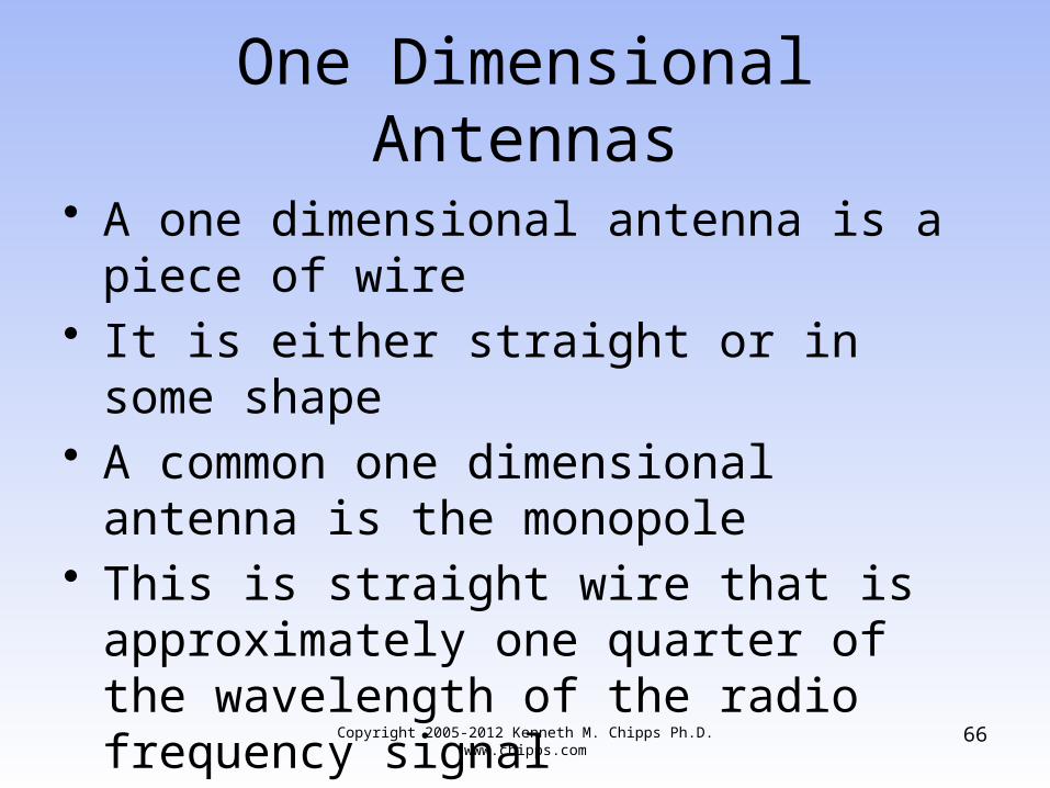
• A one dimensional antenna is a piece of wire
• It is either straight or in some shape• A common one dimensional antenna is the
monopole• This is straight wire that is approximately
one quarter of the wavelength of the radio frequency signal
Copyright 2005-2012 Kenneth M. Chipps Ph.D. www.chipps.com
66

One Dimensional Antennas
• Another common type is the dipole, which is two monopoles connected together
• Dipoles are commonly used, since a half wavelength antenna radiates radio frequency energy really well
• A monopole stuck in the ground acts like a dipole
• Therefore, it only needs to be half as long as the dipole
Copyright 2005-2012 Kenneth M. Chipps Ph.D. www.chipps.com
67

Two Dimensional Antennas
• When antennas use two dimensions they may look like almost anything from a patch to a dish as detailed below
Copyright 2005-2012 Kenneth M. Chipps Ph.D. www.chipps.com
68
Deploying Antennas
• When deploying an antenna there are several factors to consider including– Line of Site– Fresnel Zone
Copyright 2005-2012 Kenneth M. Chipps Ph.D. www.chipps.com
69

Line of Site
• LOS – Line of Sight means the ability of one antenna to see the other antenna
• As in
Copyright 2005-2012 Kenneth M. Chipps Ph.D. www.chipps.com
70

Line of Site
Copyright 2005-2012 Kenneth M. Chipps Ph.D. www.chipps.com
71

Fresnel Zone
• The Fresnel Zone is an ellipsoid around the direct line of sight between two antennas
• The first Fresnel zone is a surface containing all points for which the sum of the distances from that point to the ends is exactly ½ wavelength longer than the direct path
Copyright 2005-2012 Kenneth M. Chipps Ph.D. www.chipps.com
72

Fresnel Zone
• Each subsequent Fresnel zone surrounding this first zone is some multiple of ½ wavelength either in phase out of phase with the direct wave, thereby producing constructive or destructive multipath signals
• Anything that extends into the first Fresnel zone, such as trees, hills, buildings, can diffract or reflect or degrade the signal
Copyright 2005-2012 Kenneth M. Chipps Ph.D. www.chipps.com
73

Fresnel Zone
• This zone is three dimensional• Therefore account for objects that protrude
in from the sides as well as those that stick up
• The higher the frequency, the shorter the Fresnel Zone
• Also the longer the path, the broader the zone
Copyright 2005-2012 Kenneth M. Chipps Ph.D. www.chipps.com
74

Fresnel Zone
• Usually up to 20% to 40% blockage of the Fresnel Zone will not cause a problem
• Envision this as a slightly elongated football with a string running through the middle of it connecting the two points
• The football is the Fresnel Zone and the string is the visual line of sight
Copyright 2005-2012 Kenneth M. Chipps Ph.D. www.chipps.com
75

Fresnel Zone
Copyright 2005-2012 Kenneth M. Chipps Ph.D. www.chipps.com
76

Fresnel Zone
• To calculate the height of the Fresnel zone use this formula for meters
– h = height of the Fresnel zone in meters– dFirstEnd = distance between the first antenna and the tip of the
obstacle in kilometers– dSecondEnd = distance from the second antenna to the tip of
the obstacle in kilometers– f = frequency in GHz
Copyright 2005-2012 Kenneth M. Chipps Ph.D. www.chipps.com
77
dSecondEnddFirstEndf
dSecondEnd*dFirstEnd3.17h

Fresnel Zone
• To calculate the height of the Fresnel zone use this formula for feet
– h = height of the Fresnel zone in feet– dFirstEnd = distance between the first antenna and the tip of the
obstacle in miles– dSecondEnd = distance from the second antenna to the tip of
the obstacle in miles– f = frequency in GHz
Copyright 2005-2012 Kenneth M. Chipps Ph.D. www.chipps.com
78
dSecondEnddFirstEndf
dSecondEnd*dFirstEnd1.72h

Fresnel Zone
• The two formulas just shown assume the obstacle has a fairly sharp point at the top, such as a single tower
• If the obstacle is more like a wide, flat top, hill; then the loss is much higher
• Further, this also assumes there is just one thing in the way
• Many times there are several obstacles along the way
Copyright 2005-2012 Kenneth M. Chipps Ph.D. www.chipps.com
79

Fresnel Zone
• It is very difficult to model such a thing• This is why a fade margin is used• It attempts to account for all of these
things for which exact calculations cannot be done
Copyright 2005-2012 Kenneth M. Chipps Ph.D. www.chipps.com
80

Lab
• Compute Fresnel Zone
Copyright 2005-2012 Kenneth M. Chipps Ph.D. www.chipps.com
81

Earth Bulge
• For distances over seven miles the curvature of the earth must be considered
• The formula for this is
– h = additional height required in feet– D = distance between the antennas in miles
• This formula yields the additional antenna height required to account for the bulge
Copyright 2005-2012 Kenneth M. Chipps Ph.D. www.chipps.com
82
8
Dh
2

Intentional Radiator
• An intentional radiator is the entire RF system, except for the antenna itself
• As in
Copyright 2005-2012 Kenneth M. Chipps Ph.D. www.chipps.com
83

Intentional Radiator
Copyright 2005-2012 Kenneth M. Chipps Ph.D. www.chipps.com
84

Intentional Radiator
• The power output of the intentional radiator is the power output at the end of the last connection before the antenna
Copyright 2005-2012 Kenneth M. Chipps Ph.D. www.chipps.com
85

EIRP
• EIRP – Equivalent Isotropically Radiated Power is the power actually radiated by the antenna itself
• It includes the gain added by the antenna• This power level is regulated by the FCC• EIRP = Transmit Power + Antenna Gain• or• EIRP = dBW/dBm+dBi-Line Loss
Copyright 2005-2012 Kenneth M. Chipps Ph.D. www.chipps.com
86

EIRP
Copyright 2005-2012 Kenneth M. Chipps Ph.D. www.chipps.com
87

Lab
• Computer EIRP of Various Radio and Antenna Combinations
Copyright 2005-2012 Kenneth M. Chipps Ph.D. www.chipps.com
88

Other Radiators
• There are two other types of radiators– Unintentional Radiator
• These devices generate radio frequency emissions inside themselves incidental to their normal operation
• But they are not intended to emit these• Such as computers, printers, and disk drives
Copyright 2005-2012 Kenneth M. Chipps Ph.D. www.chipps.com
89

Other Radiators
– Incidental Radiator• These devices generate radio frequency energy as
part of their normal operation• But they are not intended to emit these• Such as motors and generators
Copyright 2005-2012 Kenneth M. Chipps Ph.D. www.chipps.com
90

Power Output Rules
• One of the ways various regulatory bodies ensure everyone can share the same unlicensed spectrum is to impose rules concerning the maximum power output
• This is expressed as the maximum EIRP that may be radiated from the antenna
Copyright 2005-2012 Kenneth M. Chipps Ph.D. www.chipps.com
91

Power Output Rules
• The rules that apply depend on two factors– Is this an experienced or any inexperienced
person installing the equipment– Is this a Point to multipoint or a point-to-point
link • Here are the rules
Copyright 2005-2012 Kenneth M. Chipps Ph.D. www.chipps.com
92

Power Output Rules
Point to Multipoint Rules
Type of User Radio Power Antenna Gain EIRP
Consumer 30 dBm 6 dBm 36 dBm
Experienced Installer 20 dBm 36 dBm 36 dBm
Copyright 2005-2012 Kenneth M. Chipps Ph.D. www.chipps.com
93

Power Output Rules
Point to Point Rules
Type of User Radio Power Antenna Gain EIRP
Consumer 30 dBm 6 dBm 36 dBm
Experienced Installer 20 dBm 36 dBm 56 dBm
Copyright 2005-2012 Kenneth M. Chipps Ph.D. www.chipps.com
94

Power Output Rules
• In addition for the 5 GHz UNII bands there are power output limits depending on which UNII band is being used
Copyright 2005-2012 Kenneth M. Chipps Ph.D. www.chipps.com
95

Power Output Rules
UNII Band Maximum Radio Power EIRP
UNII-1 50 mW 22 dBm
UNII-2 250 mW 29 dBm
UNII-2 Extended 1 W 36 dBm
UNII-3 1 W 36 dB,
Copyright 2005-2012 Kenneth M. Chipps Ph.D. www.chipps.com
96

Antenna Forms
• The basic types of antennas are– Dipole– Vertical– Parabolic Dish or Grid– Yagi– Sector– Patch or Panel– Adaptive
Copyright 2005-2012 Kenneth M. Chipps Ph.D. www.chipps.com
97

Antenna Forms
• These different types of antennas fall into three basic types depending on the direction the radiation field emitted from the antenna goes off in– All directions – omnidirectional– A limited direction – semidirectional– One single direction – highly directional
• These fields are called beams or lobes
Copyright 2005-2012 Kenneth M. Chipps Ph.D. www.chipps.com
98

Dipole Antenna
• A dipole is a bidirectional antenna, and its radiation pattern extends in two directions outward
• It generally consists of a base with two antenna spokes going in opposite directions
• The radiation pattern looks like a figure eight
Copyright 2005-2012 Kenneth M. Chipps Ph.D. www.chipps.com
99

Dipole Design
Copyright 2005-2012 Kenneth M. Chipps Ph.D. www.chipps.com
100

Dipole Radiation Pattern
Copyright 2005-2012 Kenneth M. Chipps Ph.D. www.chipps.com
101

Vertical Antenna
• A vertical antenna looks like the name sounds
• It sticks up in the air• A vertical antenna’s radiation pattern
extends in all directions from the unit• It looks very much like a donut, in that
there is little radiation directly above or below the antenna
Copyright 2005-2012 Kenneth M. Chipps Ph.D. www.chipps.com
102

Vertical Antenna
• The power drops as the distance from the antenna increases
• As the omnidirectional antenna’s gain goes up, the pattern height goes down into more of a pancake shape
• This is a very common type of antenna• Internally a vertical antenna is a series of
stacked dipoles
Copyright 2005-2012 Kenneth M. Chipps Ph.D. www.chipps.com
103

Vertical Antenna
• As more dipole elements are added the gain of the antenna increases
Copyright 2005-2012 Kenneth M. Chipps Ph.D. www.chipps.com
104

Vertical Design – Outside
Copyright 2005-2012 Kenneth M. Chipps Ph.D. www.chipps.com
105

Vertical Design - Indoor
Copyright 2005-2012 Kenneth M. Chipps Ph.D. www.chipps.com
106
Antenna is mounted to a ceiling tile
Antenna diameter is 88 mm or 3.5 inches

Vertical Radiation Pattern
Copyright 2005-2012 Kenneth M. Chipps Ph.D. www.chipps.com
107

Parabolic Dish or Grid Antenna
• Not used in LANs, but widely used in CANs and MANs, is the parabolic dish or grid antenna
• A parabolic antenna can take several forms
• In general they are circular or square• If circular, they look like a small satellite
dish
Copyright 2005-2012 Kenneth M. Chipps Ph.D. www.chipps.com
108

Parabolic Dish or Grid Antenna
• If square, they look like a wire grid• For even more gain and directivity a shield
can be placed around the dish• This is a short cylinder on to the front• This type of antenna is a unidirectional
antenna, meaning that it transmits in one specific direction
• Which is the direction at which the antenna is pointed
Copyright 2005-2012 Kenneth M. Chipps Ph.D. www.chipps.com
109

Parabolic Dish Design
Copyright 2005-2012 Kenneth M. Chipps Ph.D. www.chipps.com
110

Parabolic Grid Design
Copyright 2005-2012 Kenneth M. Chipps Ph.D. www.chipps.com
111

Parabolic Radiation Pattern
Copyright 2005-2012 Kenneth M. Chipps Ph.D. www.chipps.com
112

Yagi Antenna
• A yagi antenna is slightly less powerful than a parabolic antenna
• It too is mostly used in a CAN environment• Like the parabolic, the yagi is also
unidirectional• A yagi antenna consists of a series of
metal spokes radiating from a central core
Copyright 2005-2012 Kenneth M. Chipps Ph.D. www.chipps.com
113

Yagi Design
• These spokes are often covered, so they are not apparent when looking at the antenna
• This cover is called a radome• The yagi antenna has many variations• It normally consists of two or three
elements
Copyright 2005-2012 Kenneth M. Chipps Ph.D. www.chipps.com
114

Yagi Design
• The basic elements of the three-element yagi are a radiator, a reflector, and a director
• The radiator is the main element• To add gain and change the radiation
pattern so that it is directional, a director element is added in front of the radiator, while the reflector element is behind the radiator
Copyright 2005-2012 Kenneth M. Chipps Ph.D. www.chipps.com
115

Yagi Design
• As discussed above in more detail, the director element is slightly shorter than the radiator while the reflector element is slightly longer
• For really high gain both of these methods are used
• To increase the gain even more directors are added in front of the main director
Copyright 2005-2012 Kenneth M. Chipps Ph.D. www.chipps.com
116

Yagi Design
• Generally, each additional director is shorter than the previous one and spaced such that the overall length of the antenna is increased
Copyright 2005-2012 Kenneth M. Chipps Ph.D. www.chipps.com
117

Yagi Design - Internal
Copyright 2005-2012 Kenneth M. Chipps Ph.D. www.chipps.com
118
REFLECTOR
RADIATOR
DIRECTOR DIRECTION
OF
BEAM

Yagi Design - External
Copyright 2005-2012 Kenneth M. Chipps Ph.D. www.chipps.com
119

Yagi Design - External
Copyright 2005-2012 Kenneth M. Chipps Ph.D. www.chipps.com
120

Yagi Radiation Pattern
Copyright 2005-2012 Kenneth M. Chipps Ph.D. www.chipps.com
121

Sector Antenna
• Sector antennas are generally used to provide wide bands of coverage from a central point, such as an outside wireless base station
• Sector antennas provide the ability to aim the signal where it is needed
• It is possible to increase coverage by using multiple sector antennas all mounted on the same tower
Copyright 2005-2012 Kenneth M. Chipps Ph.D. www.chipps.com
122

Sector Antenna
• Sector antennas generally offer greater gain than omni-directional antennas and offer better flexibility and noise rejection
• Most sector antennas are designed to be down-tilted for better coverage
• This tilt redirects the beam down toward the surface
Copyright 2005-2012 Kenneth M. Chipps Ph.D. www.chipps.com
123

Sector Antenna
• This is required when a narrow vertical beamwidth, present in a high gain antenna, cannot reach the areas that need the signal or to limit co-channel interference
• The downtilt can be mechanical or electrical
• Mechanical downtilt is shown below
Copyright 2005-2012 Kenneth M. Chipps Ph.D. www.chipps.com
124

Sector Antenna
• Electrical tilting, sometimes called null fill, is created by controlling the current phase in the antenna as part of the antenna’s design
Copyright 2005-2012 Kenneth M. Chipps Ph.D. www.chipps.com
125

Sector Mechanical Downtilt
Copyright 2005-2012 Kenneth M. Chipps Ph.D. www.chipps.com
126

Sector Downtilt
• The degree of downtilt must be accurately calculated so that the desired area is covered
• As in
Copyright 2005-2012 Kenneth M. Chipps Ph.D. www.chipps.com
127

Sector Downtilt
Copyright 2005-2012 Kenneth M. Chipps Ph.D. www.chipps.com
128

Sector Downtilt• Two calculations must be made• One is for the inner radius of the coverage
– ID = Inner radius distance– H = Antenna height– A = Downtilt angle– BW = The antenna’s beamwidth
Copyright 2005-2012 Kenneth M. Chipps Ph.D. www.chipps.com
129
52802
BWA(Tan
H
ID

Sector Downtilt
• The other is for the outer radius of coverage
– OD = Outer radius distance
Copyright 2005-2012 Kenneth M. Chipps Ph.D. www.chipps.com
130
52802
BWA(Tan
H
OD

Sector Downtilt
• For example with the following– H = 100 feet– A = 8 degrees– BW = 8 degrees
• The calculated coverage is from .09 miles to .27 miles
• However this is not an absolute limit as the power does not abruptly quit, rather it falls off gradually
Copyright 2005-2012 Kenneth M. Chipps Ph.D. www.chipps.com
131

Sector Downtilt
• The point is this is the area of maximum signal strength, not the only signal strength
• The point to downtiling an antenna is to deliver the maximum power to the far off sites
Copyright 2005-2012 Kenneth M. Chipps Ph.D. www.chipps.com
132

Sector Antenna
• In the frequency ranges used for wireless MANs, a sector antenna can provide coverage up to ten miles if used in conjunction with highly directional end-station antennas, such as a parabolic style
Copyright 2005-2012 Kenneth M. Chipps Ph.D. www.chipps.com
133

Sector Design
Copyright 2005-2012 Kenneth M. Chipps Ph.D. www.chipps.com
134

Sector Radiation Pattern
Copyright 2005-2012 Kenneth M. Chipps Ph.D. www.chipps.com
135

Patch Panel Microstrip Antenna
• This type of antenna goes by several names from patch to panel to microstrip
• All of these are basically flat, totally enclosed antennas
• These antennas are generally used for short-distance point-to-point links, such as building-to-building, or short-distance end-station customer premises equipment, less than 1 mile
Copyright 2005-2012 Kenneth M. Chipps Ph.D. www.chipps.com
136

Patch or Panel Design
• The panel antenna uses a trough reflector, where the sides are folded in so that they are at right angles to the back plane
• Ends are then added to complete the box• A cover or radome is added to over the
elements
Copyright 2005-2012 Kenneth M. Chipps Ph.D. www.chipps.com
137

Patch or Panel Design
Copyright 2005-2012 Kenneth M. Chipps Ph.D. www.chipps.com
138Photograph courtesy of Telex

Microstrip Design
Copyright 2005-2012 Kenneth M. Chipps Ph.D. www.chipps.com
139
Photograph courtesy of Telex

Patch Panel Radiation Pattern
Copyright 2005-2012 Kenneth M. Chipps Ph.D. www.chipps.com
140

Adaptive Antenna Systems
• Adaptive antennas dynamically change the form of their beam or in this case beams to match the conditions
• Here is some detail on this from a March 2012 webinar presented by Douglas Morais
Copyright 2005-2012 Kenneth M. Chipps Ph.D. www.chipps.com
141

Adaptive Antenna Systems
– In an Adaptive Antenna System (AAS),also called an Adaptive Beamforming system, an array of antennas is used adaptively for reception, transmission, or both, in a way that seeks to optimize transmission over the channel
– In a PMP system, array usually at BS, and forms beams adaptively that target individual remote, not a sector or an entire cell
Copyright 2005-2012 Kenneth M. Chipps Ph.D. www.chipps.com
142

Adaptive Antenna Systems
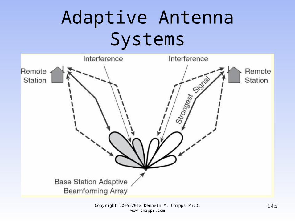
– Able to do this by creating multiple beams simultaneously, each beam directed to a specific remote
– Shape of each beam can be dynamically controlled so that signal strength to and from a remote is maximized
– Does this by directing main lobe in direction of strongest signal component, and sidelobes in the direction of multipath components
Copyright 2005-2012 Kenneth M. Chipps Ph.D. www.chipps.com
143

Adaptive Antenna Systems
– Further, it can simultaneously minimize interference of signals that arrive at a different direction from the desired by locating nulls in direction of interference, thus maximizing SINR
– Beams from adaptive beamforming antenna array communicating with two remote stations
Copyright 2005-2012 Kenneth M. Chipps Ph.D. www.chipps.com
144
Adaptive Antenna Systems
Copyright 2005-2012 Kenneth M. Chipps Ph.D. www.chipps.com
145

Lab
• Find One of Each Type of Antenna
Copyright 2005-2012 Kenneth M. Chipps Ph.D. www.chipps.com
146

Antenna Diversity
• Most access points come with either a single dipole antenna or diversity antennas
• A diversity antenna is simply multiple antennas connected to a single receiver
• This helps to overcome multipath reception problems when the access point cannot be moved
Copyright 2005-2012 Kenneth M. Chipps Ph.D. www.chipps.com
147

Antenna Diversity
• For diversity to be effective the two antennas should be placed at least 15 cm or six inches apart
• Separation greater than 250 cm or eight feet is not generally required for the diversity function to be effective
Copyright 2005-2012 Kenneth M. Chipps Ph.D. www.chipps.com
148

MIMO Antenna
• MIMO - Multiple Input Multiple Output antennas use multiple transmit and receive antennas in a single unit
• The MIMO algorithm in the radio chipset sends the data out two or more antennas
• These signals reflect off objects, in other words multipath interference
Copyright 2005-2012 Kenneth M. Chipps Ph.D. www.chipps.com
149

MIMO Antenna
• But the MIMO algorithm uses these multiple paths to send not the same data but additional data
• At the other end these signals are recombined
• MIMO also allows an access point to grab multiple different radio-frequency streams and choose the best one for better performance
Copyright 2005-2012 Kenneth M. Chipps Ph.D. www.chipps.com
150

Selecting an Antenna
• There are several parameters to consider when selecting an antenna
• These parameters are– Antenna Gain – Beamwidth– Loss– Radiation Pattern
Copyright 2005-2012 Kenneth M. Chipps Ph.D. www.chipps.com
151

Antenna Gain
• Antenna gain is an indicator of how well the antenna focuses a signal
• This is measured in dBi - decibels relative to isotropic radiator, which is a theoretically perfect antenna
• The dBi is computed by comparing the output of the antenna to the theoretically perfect antenna
Copyright 2005-2012 Kenneth M. Chipps Ph.D. www.chipps.com
152

Antenna Gain
• The higher the dBi measurement, the higher the power level of the antenna
Copyright 2005-2012 Kenneth M. Chipps Ph.D. www.chipps.com
153
Beamwidth
• The beamwidth of the antenna is the area radiating outward from the antenna, where the signal within a specified angular distance is still higher than the half power of the peak intensity of the antenna
• This suggests the antenna type to use
Copyright 2005-2012 Kenneth M. Chipps Ph.D. www.chipps.com
154

Beamwidth
• For example, the parabolic antenna is a unidirectional antenna with a very low beamwidth, which means that it needs to be very carefully aimed in order to work properly
• A vertical antenna, being omnidirectional has a very high horizontal beamwidth, which is why it’s suitable for covering a large circular area
Copyright 2005-2012 Kenneth M. Chipps Ph.D. www.chipps.com
155

Beamwidth
• In general, there’s an inverse relationship between beamwidth and antenna gain
• So as gain increases the beamwidth decreases
• Therefore the antenna must be more carefully aimed
• For example
Copyright 2005-2012 Kenneth M. Chipps Ph.D. www.chipps.com
156

BeamwidthHorizontal Beamwidth Vertical Beamwidth Maximum Gain
dBi
360 8 11.6
360 15 8.8
150 15 12.6
150 30 9.6
120 30 10.6
120 60 7.6
90 15 14.9
90 30 11.9
60 30 13.6
60 60 10.6
Copyright 2005-2012 Kenneth M. Chipps Ph.D. www.chipps.com
157

Loss
• Loss affects a wireless deployment, especially at higher power levels
• Loss is a result of the signal having to travel from the access point to the antenna
• Since these parts are always connected by a cable, there will always be loss
• To minimize the loss use the correct cable, usually coax, and the minimum length possible
Copyright 2005-2012 Kenneth M. Chipps Ph.D. www.chipps.com
158

Radiation Pattern
• As shown above every type of antenna has a different radiation pattern based on its construction
• This is a three-dimensional field• It reflects the output of the antenna at any
point in space
Copyright 2005-2012 Kenneth M. Chipps Ph.D. www.chipps.com
159

Radiation Pattern
• If it is available from the manufacturer, get a copy of the radiation pattern for the antenna you will be using to see what the coverage area will look like
Copyright 2005-2012 Kenneth M. Chipps Ph.D. www.chipps.com
160

Antenna Parameters in General
• You can use the parameters just discussed to determine where access points need to be placed
• In particular how far the signal from a particular antenna can travel before becoming unusable
Copyright 2005-2012 Kenneth M. Chipps Ph.D. www.chipps.com
161

Antenna Parameters in General
• As a rule of thumb, a directional antenna has a pattern of coverage shaped like a cone that radiates in the direction that the antenna is pointed, while an omnidirectional antenna’s area of coverage is shaped like a doughnut
Copyright 2005-2012 Kenneth M. Chipps Ph.D. www.chipps.com
162

What is an Amplifier
• Things often need to get bigger• In radio frequency systems an amplifier
does this
Copyright 2005-2012 Kenneth M. Chipps Ph.D. www.chipps.com
163

Amplifier Properties
• There are three basic properties of amplifiers– Gain– Noise figure or output power– Linearity
Copyright 2005-2012 Kenneth M. Chipps Ph.D. www.chipps.com
164

Amplifier Gain
• Gain is a measure of how much larger the output is over the input
• It is measured in dB• In a radio frequency system a lot of gain is
40 to 50 dBs and a little is 5 to 10 dBs
Copyright 2005-2012 Kenneth M. Chipps Ph.D. www.chipps.com
165

Noise or Power
• Amplifiers are categorized as– Low noise– High power– Other
Copyright 2005-2012 Kenneth M. Chipps Ph.D. www.chipps.com
166

Noise or Power
• In radio frequency systems a low noise amplifier is the first amplifier after the signal comes through the antenna in a receiver and a high power amplifier is the last amplifier it goes through when going out a transmitter
• Everything else is an other
Copyright 2005-2012 Kenneth M. Chipps Ph.D. www.chipps.com
167

Low Noise Amplifier
• A LNA - Low Noise Amplifier is used to take the very small radio frequency signal and make it into something that is useable
• As the signal is small, if a bunch of noise is added to it, that would drown out the signal
• So a LNA is very useful in such a case• Noise is measured as an NF figure, the
lower the betterCopyright 2005-2012 Kenneth M. Chipps Ph.D.
www.chipps.com168

High Power Amplifier
• A HPA - High Power Amplifier is used to boost the signal up to the allowable limit just before it is launched into the air
• HPAs are measured in watts more or less• These watts are expressed as the dBs
above one milliwatt of dBm• In other words 30 dBm is a signal 30 dB
above 1 mW or 1000 times larger than 1 mW or 1 watt
Copyright 2005-2012 Kenneth M. Chipps Ph.D. www.chipps.com
169

Linearity
• When sending digital signals linearity is important
• Linearity refers to how much the signal’s shape is distorted
• What is desired is a signal coming out of the amplifier that is larger than what went in and of the same shape
• This is shown as a transfer curve
Copyright 2005-2012 Kenneth M. Chipps Ph.D. www.chipps.com
170

Linearity
• A transfer curve is a graph of the output power versus the input power of an amplifier
• A characteristic of an amplifier is that as the input power to an amplifier increases the output power also increases by a like amount up to a point
• This portion of the curve is the linear portion
Copyright 2005-2012 Kenneth M. Chipps Ph.D. www.chipps.com
171

Linearity
• The end of this part of the curve is called the P1dB, pronounced as the “p wun’ db” point
• This point is the highest at which an amplifier can put out linear power
• Above the P1dB point the power increases, but not in a linear fashion
Copyright 2005-2012 Kenneth M. Chipps Ph.D. www.chipps.com
172

Special Types of Amplifiers
• There are three special types of amplifiers encountered in radio frequency systems– Limiting– Balanced– Variable Gain
Copyright 2005-2012 Kenneth M. Chipps Ph.D. www.chipps.com
173

Limiting Amplifier
• A limiting amplifier limits the output power• This type is used when the component
that follows the amplifier would be damaged by too much power coming into it from the amplifier
Copyright 2005-2012 Kenneth M. Chipps Ph.D. www.chipps.com
174
Balanced Amplifier
• An amplifier using a balanced design is really two amplifiers in one
• The radio frequency signal enters one side of the amplifier
• Once inside the signal is split into two parts
• Half goes to one amplifier and the other half to the other amplifier
Copyright 2005-2012 Kenneth M. Chipps Ph.D. www.chipps.com
175

Balanced Amplifier
• The two signals are then added back together before leaving the amplifier
• The advantage to this design is that if one amplifier inside fails, the other can keep working
• This design leaks less, which means less VSWR
Copyright 2005-2012 Kenneth M. Chipps Ph.D. www.chipps.com
176
Variable Gain Amplifier
• A variable gain amplifier merely has a control that can be used to adjust the gain
Copyright 2005-2012 Kenneth M. Chipps Ph.D. www.chipps.com
177

What is a Filter
• A filter filters signals• Such as a bunch of signals all at different
frequencies coming in and just one, the desired one, going back out
• In essence a filter is the door bouncer at a trendy club
• Some get in and some are kept out
Copyright 2005-2012 Kenneth M. Chipps Ph.D. www.chipps.com
178

Use of Filters
• Filters are used at the receive side as the antenna will pick up signals at and near the desired frequency
• The filter removes the undesired ones• Governmental regulatory authorities say
you may only transmit on the authorized frequency
• The filter is designed to ensure this is the case
Copyright 2005-2012 Kenneth M. Chipps Ph.D. www.chipps.com
179
Types of Filters
• There are four types of filters– Low pass
• Letting all frequencies below a certain frequency to pass– High pass
• Letting all frequencies above a certain frequency to pass– Bandpass
• Allows all frequencies between two frequencies to pass– Band reject – notch filter
• Prevents all frequencies between two frequencies from passing
Copyright 2005-2012 Kenneth M. Chipps Ph.D. www.chipps.com
180
Filter Operation
• Filters do their work by varying their insertion loss as a function of the frequency they see
• This is the frequency response of the filter
Copyright 2005-2012 Kenneth M. Chipps Ph.D. www.chipps.com
181

What is a Mixer
• A mixer seeks to change the frequency of a signal while keeping everything else about the signal the same
• But why would you want to do this• One reason would be that your voice
creates sound in the area of 2,000 Hertz, but a cell phone operates at 900,000,000 Hertz
Copyright 2005-2012 Kenneth M. Chipps Ph.D. www.chipps.com
182

Mixer Operation
• Mixers have three ports, two input and one output– The RF port is the higher frequency signal
port– The IF port is the lower frequency port– The LO port connects to a source or oscillator
• Mixers are not perfect things• This is why a filter always follows a mixer
Copyright 2005-2012 Kenneth M. Chipps Ph.D. www.chipps.com
183

Mixer Operation
• It gets rid of what is produced, but not needed
• A mixer also produces other problems• Being a passive component the mixer
exhibits loss as it does its work• This is the conversion loss or CL• The lower the CL figure the better
Copyright 2005-2012 Kenneth M. Chipps Ph.D. www.chipps.com
184

Mixer Operation
• A mixer also produces noise• The lower the noise figure or NF the better
Copyright 2005-2012 Kenneth M. Chipps Ph.D. www.chipps.com
185

Two Stage Mixer
• A two stage mixer is not really a type but rather a way of using mixers
• In this setup there are two mixers, one after the other
• The signal between the two is called the baseband signal
Copyright 2005-2012 Kenneth M. Chipps Ph.D. www.chipps.com
186

What is a Source
• The source or oscillator is what generates the radio frequency
• The desire is to produce a perfect sine wave at the desired frequency
• Of course this never happens
Copyright 2005-2012 Kenneth M. Chipps Ph.D. www.chipps.com
187

Other Components
• Besides the five main components used in radio frequency systems– Antenna– Amplifier– Mixer– Filter– Source
Copyright 2005-2012 Kenneth M. Chipps Ph.D. www.chipps.com
188

Other Components
• There are several more you will encounter from time to time
• These include• Switch• Attenuator• Divider and Combiner• Coupler• Circulator and Isolator
Copyright 2005-2012 Kenneth M. Chipps Ph.D. www.chipps.com
189

Other Components
• Transformer• Detector• Phase Shifter• Phase Detector
Copyright 2005-2012 Kenneth M. Chipps Ph.D. www.chipps.com
190

Other Components
• In general all of these other devices do one of two things– They send the radio frequency signal in a
different direction or multiple directions– or– They change the size or shape of the signal
Copyright 2005-2012 Kenneth M. Chipps Ph.D. www.chipps.com
191
Switch
• Switches change the path of a radio frequency signal
• Switch performance is based on– Amount of loss– Switching speed
• In a switch there are two kinds of loss– Insertion loss– Isolation loss
Copyright 2005-2012 Kenneth M. Chipps Ph.D. www.chipps.com
192

Switch
• Insertion loss is the reduction in the signal just because it went through the switch
• Isolation loss is produced by the gap created when the switch is open
• Of course insertion loss should be kept low
• Isolation loss should be kept high
Copyright 2005-2012 Kenneth M. Chipps Ph.D. www.chipps.com
193

Switch
• Switches are commonly used in radio frequency systems so that a single antenna can be used for both transmitting and receiving
Copyright 2005-2012 Kenneth M. Chipps Ph.D. www.chipps.com
194

Attenuator
• An attenuator creates loss• The key point here is that an attenuator is
used to insert a known amount of loss for some reason related to a circuit’s design
• Attenuators can be– Fixed– Variable
• A fixed attenuator is sometimes called a pad
Copyright 2005-2012 Kenneth M. Chipps Ph.D. www.chipps.com
195

Divider or Combiner
• Dividers divide a signal into two or more parts, usually two or four
• The division is always equal in size• These are also called power dividers• Combiners combine signals• As with most devices low insertion loss is
desired
Copyright 2005-2012 Kenneth M. Chipps Ph.D. www.chipps.com
196

Coupler
• A coupler is used to draw a sample of a radio frequency signal off for some use, such as feedback to a circuit so that it can correct the signal before it is sent out
• Performance measures of couplers include– Insertion loss– Coupling accuracy
• Which is that the signal that is sampled is accurateCopyright 2005-2012 Kenneth M. Chipps Ph.D.
www.chipps.com197

Circulator
• In a circulator a signal that comes in travels around in a circle until it encounters an exit, then it must get off
• A circulator is a form of a switch• For example
Copyright 2005-2012 Kenneth M. Chipps Ph.D. www.chipps.com
198

Circulator
Copyright 2005-2012 Kenneth M. Chipps Ph.D. www.chipps.com
199

Circulator
• Any signal coming in from the antenna must get off at the receiver
• Any signal coming from the transmitter must get off at the antenna
• So we have a simple, but smart switch• Low insertion loss is desirable
Copyright 2005-2012 Kenneth M. Chipps Ph.D. www.chipps.com
200

Isolator
• A special type of circulator that only uses two of the three ports is called an isolator
• The isolator is used to draw off reflected power as heat so that this reflected power does not go back down the line and damage something
• Low insertion loss is desirable
Copyright 2005-2012 Kenneth M. Chipps Ph.D. www.chipps.com
201

Transformer
• A transformer, transforms• In the radio frequency world the thing
being transformed is impedance• In other words it takes one thing, like an
impedance of 100 ohms, and changes it to another thing, like an impedance of 50 ohms
• The main performance measure is the impedance ratio
Copyright 2005-2012 Kenneth M. Chipps Ph.D. www.chipps.com
202

Detector
• The detector is a power to voltage converter
• Radio frequency power enters it at one side, it comes out the other side as a voltage that is proportional to the radio frequency power
Copyright 2005-2012 Kenneth M. Chipps Ph.D. www.chipps.com
203

Detector
• The use of this device is to convert a radio frequency signal into a voltage, as there are devices that cannot handle a radio frequency signal, but they can handle a voltage
• An example is a piece of test equipment
Copyright 2005-2012 Kenneth M. Chipps Ph.D. www.chipps.com
204

Phase Shifter
• A phase shifter is used to control the phase of one signal in relation to another signal
• These are used when optimizing a circuit or as a means to provide feedback to a circuit
Copyright 2005-2012 Kenneth M. Chipps Ph.D. www.chipps.com
205

Phase Detector
• Once the phase shifter imparts a shift in phase, to be useful this shift must be detected
• This is what the phase detector does
Copyright 2005-2012 Kenneth M. Chipps Ph.D. www.chipps.com
206

Let’s Summarize
• Antenna– Active or Passive– Converts signals to and from airborne waves
• Amplifier– Active– Makes a signal larger
Copyright 2005-2012 Kenneth M. Chipps Ph.D. www.chipps.com
207

Let’s Summarize
• Filter– Passive– Separates a signal by frequency
• Mixer– Active or Passive– Increase or decrease a signal’s frequency
Copyright 2005-2012 Kenneth M. Chipps Ph.D. www.chipps.com
208

Let’s Summarize
• Oscillator– Active– Create a perfect sine wave
• Switch– Active– Change the direction a signal travels
Copyright 2005-2012 Kenneth M. Chipps Ph.D. www.chipps.com
209

Let’s Summarize
• Attenuator– Active or Passive– Make signal smaller
• Divider– Passive– Split a signal
Copyright 2005-2012 Kenneth M. Chipps Ph.D. www.chipps.com
210

Let’s Summarize
• Combiner– Passive– Add signals together
• Coupler– Passive– Split up or add two signals in unequal
proportion
Copyright 2005-2012 Kenneth M. Chipps Ph.D. www.chipps.com
211

Let’s Summarize
• Circulator– Passive– Create a smart switch
• Isolator– Passive– Protect components from signal reflection
Copyright 2005-2012 Kenneth M. Chipps Ph.D. www.chipps.com
212

Let’s Summarize
• Transformer– Passive– Change impedance
• Detector– Passive– Convert an RF signal to voltage
Copyright 2005-2012 Kenneth M. Chipps Ph.D. www.chipps.com
213

Let’s Summarize
• Phase Shifter– Active or Passive– Change the phase of one sine wave with
respect to another• Phase Detector
– Passive– Produce a voltage proportional to the
difference in phases
Copyright 2005-2012 Kenneth M. Chipps Ph.D. www.chipps.com
214

The Result – A Radio
• What is the result of putting all of these bits and pieces together
• The creation of a radio of course• A radio is used to send and receive a
signal that flows through the air as a series of electromagnetic waves
• The way these parts are put together to form the radio, as well as the quality of the parts, determines how well the radio works
Copyright 2005-2012 Kenneth M. Chipps Ph.D. www.chipps.com
215

Radio Quality
• There are several important measures used to differentiate the ability of a radio to do its work
• The main measure used to determine the ability of a radio to function is its receive sensitivity
• This is a measure of the lowest quality signal a radio can hear and decipher
Copyright 2005-2012 Kenneth M. Chipps Ph.D. www.chipps.com
216

Radio Quality
• Just because the radio can hear something means nothing
• It must be able to understand what the signal is trying to say
• The receive sensitivity is expressed as a minus dBm number
Copyright 2005-2012 Kenneth M. Chipps Ph.D. www.chipps.com
217

Radio Quality
• The larger the number the better• In other words the further away from zero
the better
Copyright 2005-2012 Kenneth M. Chipps Ph.D. www.chipps.com
218

Receive Sensitivity
dBm Value 0Poin
t
-dBm ValueThe further the number is from the 0 point the better
Worse -1 to -95 Better
Copyright 2005-2012 Kenneth M. Chipps Ph.D. www.chipps.com
219

Radio Quality
• Once the radio is in the operation it not only receives the desired signal, but all signals in the area
• The desired signal will have a value in dBm as well
• This is the signal strength level• The signal strength level is determined by
the radio based on the signal it can receive and decipher
Copyright 2005-2012 Kenneth M. Chipps Ph.D. www.chipps.com
220

Radio Quality
• The closer to the zero point the louder the signal
• Some of the signals received by the radio cannot be deciphered
• These are the undesirable signals or noise
Copyright 2005-2012 Kenneth M. Chipps Ph.D. www.chipps.com
221

Radio Quality
• Some of this noise will be from galactic noise, some from manmade noises, and some are valid signals from other radio networks
• All of this is noise or undesired signal to the radio in our network
• These signals create the noise floor
Copyright 2005-2012 Kenneth M. Chipps Ph.D. www.chipps.com
222

Radio Quality
• If the noise floor is further from the zero point than the desired signal, then we are in business
• A functioning radio communication link exists
• But keep in mind that the radio environment is unbounded
• It is subject to almost unlimited change on a second by second basis
Copyright 2005-2012 Kenneth M. Chipps Ph.D. www.chipps.com
223

Radio Quality
• To provide some margin for these varying conditions a certain SNR – Signal to Noise Ratio is desired
• The SNR is the signal strength level seen by the radio minus the noise level seen by the radio
• This noise level is also called the noise floor
Copyright 2005-2012 Kenneth M. Chipps Ph.D. www.chipps.com
224

Radio Quality
• For example with a received signal strength of -65 dBm and a noise reading of -85 dBm, then the signal to noise ratio is 20 db
• This allows a fade margin to account for the varying conditions while still maintaining a reliable radio link
Copyright 2005-2012 Kenneth M. Chipps Ph.D. www.chipps.com
225

Radio Quality
• Let’s look at an example• The Cisco PCMCIA 350 wireless NIC has
a published receive sensitivity of -85 dBm at 11 Mbps
• It also can receive at -95 dBm if the data rate is only 1 Mbps
• This is always the case
Copyright 2005-2012 Kenneth M. Chipps Ph.D. www.chipps.com
226

Radio Quality
• The lower the data rate the better the ability of the receiver to decipher the desired signal
• What values are typically seen in the field• Following is a screen shot for the client
utility that comes with the Cisco 350 PCMCIA 350 card
Copyright 2005-2012 Kenneth M. Chipps Ph.D. www.chipps.com
227

Radio Quality
Copyright 2005-2012 Kenneth M. Chipps Ph.D. www.chipps.com
228

Radio Quality
• As seen in the screenshot the signal strength is around -45 dBm and the noise level is around -88 dBm
• This produces a SNR of 45 dB• What's good and what's bad• Signal strength is determined by the
factors between the sending and receiving radios, such as distance and propagation factors
Copyright 2005-2012 Kenneth M. Chipps Ph.D. www.chipps.com
229

Radio Quality
• Noise levels vary, but -85 to -97 is commonly seen
• So this value of -88 dBm is quite normal• The worst I have heard of is -55 dBm• A desired SNR is 20 dB on a point-to-point
link• For a point-multipoint link 12 to 14 dB SNR
is adequate
Copyright 2005-2012 Kenneth M. Chipps Ph.D. www.chipps.com
230

Radio Quality
• Links will work, but not well, down to 6 dB or so
• In this example a SNR of 45 dBm is quite good
• It should be because the NIC is only 12 inches from the access point
Copyright 2005-2012 Kenneth M. Chipps Ph.D. www.chipps.com
231

Lab
• Find the Sensitivity Ratings for a Radio
Copyright 2005-2012 Kenneth M. Chipps Ph.D. www.chipps.com
232

Review
• What is a radio• What determines radio quality
Copyright 2005-2012 Kenneth M. Chipps Ph.D. www.chipps.com
233