Embed Size (px)
Citation preview
Radio Frequency Electromagnetic Exposure
CDMA/GSM/LTE/WCDMA
Safety Information
5/124 46-LZA 701 6001 Uen Rev BN
Radio Frequency Electromagnetic Exposure
5/124 46-LZA 701 6001 Uen Rev BN 2016-09-22 Ericsson AB 2009-2016 2 (41)
Copyright © Copyright Ericsson AB 2009-2016. All rights reserved. Disclaimer No part of this document may be reproduced in any form without the written permission of the copyright owner. The contents of this document are subject to revision without notice due to continued progress in methodology, design and manufacturing. Ericsson shall have no liability for any error or damage of any kind resulting from the use of this document.
Radio Frequency Electromagnetic Exposure
5/124 46-LZA 701 6001 Uen Rev BN 2016-09-22 Ericsson AB 2009-2016 3 (41)
Contents
1 Introduction ............................................................................. 4
2 Compliance Boundaries for Electromagnetic Exposure ...... 5 2.1 Macro RBS ............................................................................... 5 2.2 Micro RBS............................................................................... 20 2.3 Pico RBS ................................................................................ 33 2.4 Radio Dot System ................................................................... 39
References............................................................................................... 41
Radio Frequency Electromagnetic Exposure
5/124 46-LZA 701 6001 Uen Rev BN 2016-09-22 Ericsson AB 2009-2016 4 (41)
1 Introduction
This document provides information on Radio Frequency (RF) Electromagnetic Field (EMF) exposure from antennas either integrated in or connected to a radio base station (RBS) or a radio unit in the RBS 6000 family.
Radio Frequency Electromagnetic Exposure
5/124 46-LZA 701 6001 Uen Rev BN 2016-09-22 Ericsson AB 2009-2016 5 (41)
2 Compliance Boundaries for Electromagnetic Exposure
The compliance boundary defines the minimum separations that should be kept between the antenna and a person to ensure that the ICNIRP [1], FCC [2] and Industry Canada [3] RF exposure limits are not exceeded.
Ericsson has performed advanced numerical or experimental RF exposure assessments in accordance with European standards [4]-[6] in order to determine compliance boundaries for minimum and maximum power configurations of the RBS product with recommended antennas. The resulting dimensions, in meters, for a compliance boundary for both general public and occupational exposure are shown in the sections below for macro and micro RBS products.
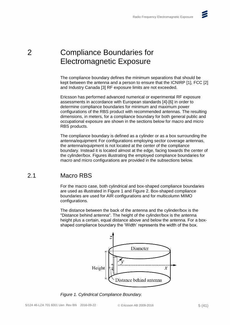
The compliance boundary is defined as a cylinder or as a box surrounding the antenna/equipment. For configurations employing sector coverage antennas, the antenna/equipment is not located at the center of the compliance boundary. Instead it is located almost at the edge, facing towards the center of the cylinder/box. Figures illustrating the employed compliance boundaries for macro and micro configurations are provided in the subsections below.
2.1 Macro RBS
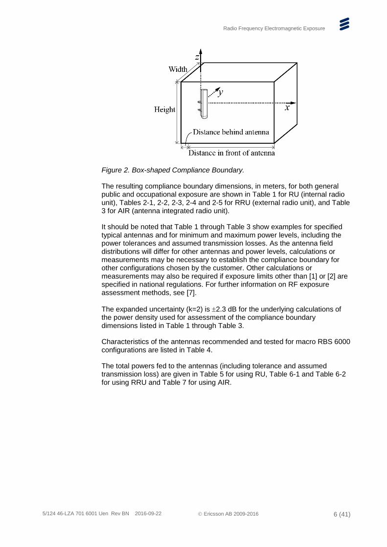
For the macro case, both cylindrical and box-shaped compliance boundaries are used as illustrated in Figure 1 and Figure 2. Box-shaped compliance boundaries are used for AIR configurations and for multicolumn MIMO configurations.
The distance between the back of the antenna and the cylinder/box is the "Distance behind antenna". The height of the cylinder/box is the antenna height plus a certain, equal distance above and below the antenna. For a box-shaped compliance boundary the ‘Width’ represents the width of the box.
Figure 1. Cylindrical Compliance Boundary.
Radio Frequency Electromagnetic Exposure
5/124 46-LZA 701 6001 Uen Rev BN 2016-09-22 Ericsson AB 2009-2016 6 (41)
Figure 2. Box-shaped Compliance Boundary.
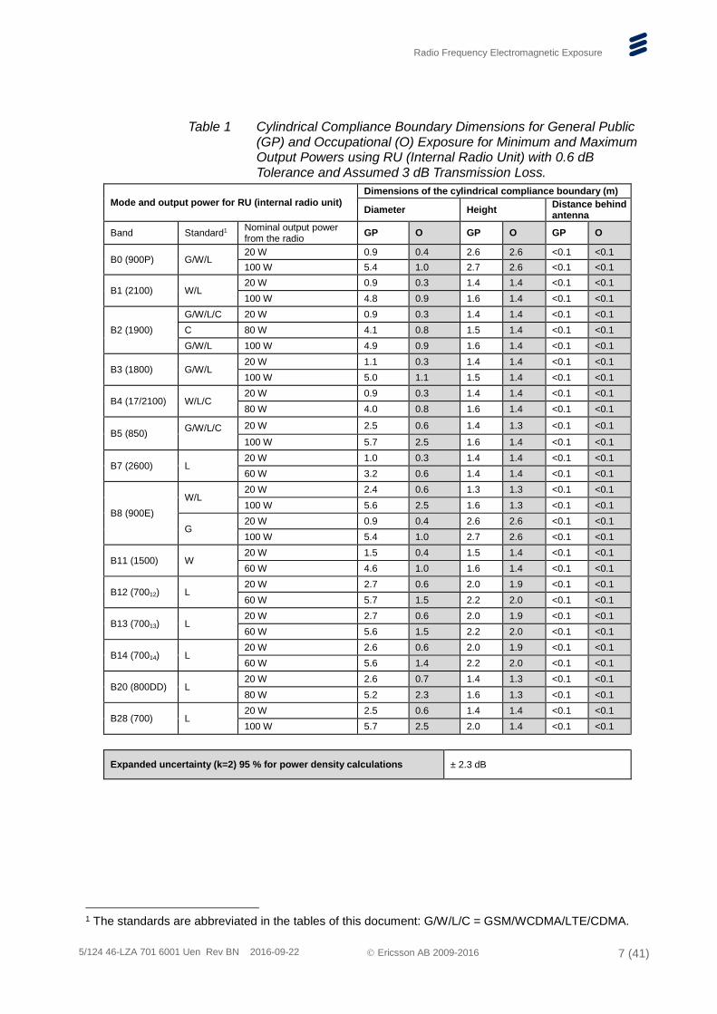
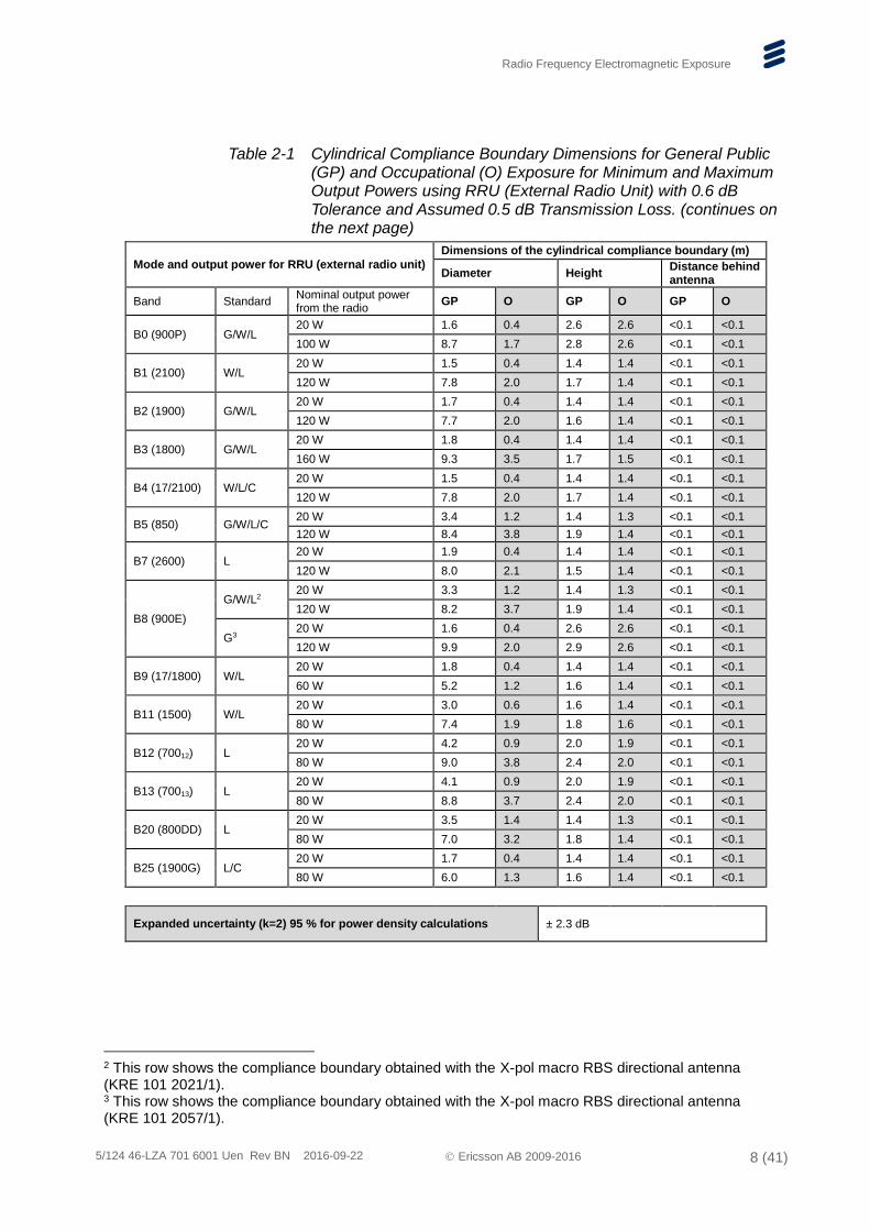
The resulting compliance boundary dimensions, in meters, for both general public and occupational exposure are shown in Table 1 for RU (internal radio unit), Tables 2-1, 2-2, 2-3, 2-4 and 2-5 for RRU (external radio unit), and Table 3 for AIR (antenna integrated radio unit).
It should be noted that Table 1 through Table 3 show examples for specified typical antennas and for minimum and maximum power levels, including the power tolerances and assumed transmission losses. As the antenna field distributions will differ for other antennas and power levels, calculations or measurements may be necessary to establish the compliance boundary for other configurations chosen by the customer. Other calculations or measurements may also be required if exposure limits other than [1] or [2] are specified in national regulations. For further information on RF exposure assessment methods, see [7].
The expanded uncertainty (k=2) is 2.3 dB for the underlying calculations of the power density used for assessment of the compliance boundary dimensions listed in Table 1 through Table 3.
Characteristics of the antennas recommended and tested for macro RBS 6000 configurations are listed in Table 4.
The total powers fed to the antennas (including tolerance and assumed transmission loss) are given in Table 5 for using RU, Table 6-1 and Table 6-2 for using RRU and Table 7 for using AIR.
Radio Frequency Electromagnetic Exposure
5/124 46-LZA 701 6001 Uen Rev BN 2016-09-22 Ericsson AB 2009-2016 7 (41)
Table 1 Cylindrical Compliance Boundary Dimensions for General Public (GP) and Occupational (O) Exposure for Minimum and Maximum Output Powers using RU (Internal Radio Unit) with 0.6 dB Tolerance and Assumed 3 dB Transmission Loss.
Mode and output power for RU (internal radio unit)
Dimensions of the cylindrical compliance boundary (m)
Diameter Height Distance behind antenna
Band Standard1 Nominal output power from the radio
GP O GP O GP O
B0 (900P) G/W/L 20 W 0.9 0.4 2.6 2.6 <0.1 <0.1
100 W 5.4 1.0 2.7 2.6 <0.1 <0.1
B1 (2100) W/L 20 W 0.9 0.3 1.4 1.4 <0.1 <0.1
100 W 4.8 0.9 1.6 1.4 <0.1 <0.1
B2 (1900)
G/W/L/C 20 W 0.9 0.3 1.4 1.4 <0.1 <0.1
C 80 W 4.1 0.8 1.5 1.4 <0.1 <0.1
G/W/L 100 W 4.9 0.9 1.6 1.4 <0.1 <0.1
B3 (1800) G/W/L 20 W 1.1 0.3 1.4 1.4 <0.1 <0.1
100 W 5.0 1.1 1.5 1.4 <0.1 <0.1
B4 (17/2100) W/L/C 20 W 0.9 0.3 1.4 1.4 <0.1 <0.1
80 W 4.0 0.8 1.6 1.4 <0.1 <0.1
B5 (850) G/W/L/C
20 W 2.5 0.6 1.4 1.3 <0.1 <0.1
100 W 5.7 2.5 1.6 1.4 <0.1 <0.1
B7 (2600) L 20 W 1.0 0.3 1.4 1.4 <0.1 <0.1
60 W 3.2 0.6 1.4 1.4 <0.1 <0.1
B8 (900E)
W/L 20 W 2.4 0.6 1.3 1.3 <0.1 <0.1
100 W 5.6 2.5 1.6 1.3 <0.1 <0.1
G 20 W 0.9 0.4 2.6 2.6 <0.1 <0.1
100 W 5.4 1.0 2.7 2.6 <0.1 <0.1
B11 (1500) W 20 W 1.5 0.4 1.5 1.4 <0.1 <0.1
60 W 4.6 1.0 1.6 1.4 <0.1 <0.1
B12 (70012) L 20 W 2.7 0.6 2.0 1.9 <0.1 <0.1
60 W 5.7 1.5 2.2 2.0 <0.1 <0.1
B13 (70013) L 20 W 2.7 0.6 2.0 1.9 <0.1 <0.1
60 W 5.6 1.5 2.2 2.0 <0.1 <0.1
B14 (70014) L 20 W 2.6 0.6 2.0 1.9 <0.1 <0.1
60 W 5.6 1.4 2.2 2.0 <0.1 <0.1
B20 (800DD) L 20 W 2.6 0.7 1.4 1.3 <0.1 <0.1
80 W 5.2 2.3 1.6 1.3 <0.1 <0.1
B28 (700) L 20 W 2.5 0.6 1.4 1.4 <0.1 <0.1
100 W 5.7 2.5 2.0 1.4 <0.1 <0.1
Expanded uncertainty (k=2) 95 % for power density calculations ± 2.3 dB
1 The standards are abbreviated in the tables of this document: G/W/L/C = GSM/WCDMA/LTE/CDMA.
Radio Frequency Electromagnetic Exposure
5/124 46-LZA 701 6001 Uen Rev BN 2016-09-22 Ericsson AB 2009-2016 8 (41)
Table 2-1 Cylindrical Compliance Boundary Dimensions for General Public (GP) and Occupational (O) Exposure for Minimum and Maximum Output Powers using RRU (External Radio Unit) with 0.6 dB Tolerance and Assumed 0.5 dB Transmission Loss. (continues on the next page)
Mode and output power for RRU (external radio unit)
Dimensions of the cylindrical compliance boundary (m)
Diameter Height Distance behind antenna
Band Standard Nominal output power from the radio
GP O GP O GP O
B0 (900P) G/W/L 20 W 1.6 0.4 2.6 2.6 <0.1 <0.1
100 W 8.7 1.7 2.8 2.6 <0.1 <0.1
B1 (2100) W/L 20 W 1.5 0.4 1.4 1.4 <0.1 <0.1
120 W 7.8 2.0 1.7 1.4 <0.1 <0.1
B2 (1900) G/W/L 20 W 1.7 0.4 1.4 1.4 <0.1 <0.1
120 W 7.7 2.0 1.6 1.4 <0.1 <0.1
B3 (1800) G/W/L 20 W 1.8 0.4 1.4 1.4 <0.1 <0.1
160 W 9.3 3.5 1.7 1.5 <0.1 <0.1
B4 (17/2100) W/L/C 20 W 1.5 0.4 1.4 1.4 <0.1 <0.1
120 W 7.8 2.0 1.7 1.4 <0.1 <0.1
B5 (850) G/W/L/C 20 W 3.4 1.2 1.4 1.3 <0.1 <0.1
120 W 8.4 3.8 1.9 1.4 <0.1 <0.1
B7 (2600) L 20 W 1.9 0.4 1.4 1.4 <0.1 <0.1
120 W 8.0 2.1 1.5 1.4 <0.1 <0.1
B8 (900E)
G/W/L2 20 W 3.3 1.2 1.4 1.3 <0.1 <0.1
120 W 8.2 3.7 1.9 1.4 <0.1 <0.1
G3 20 W 1.6 0.4 2.6 2.6 <0.1 <0.1
120 W 9.9 2.0 2.9 2.6 <0.1 <0.1
B9 (17/1800) W/L 20 W 1.8 0.4 1.4 1.4 <0.1 <0.1
60 W 5.2 1.2 1.6 1.4 <0.1 <0.1
B11 (1500) W/L 20 W 3.0 0.6 1.6 1.4 <0.1 <0.1
80 W 7.4 1.9 1.8 1.6 <0.1 <0.1
B12 (70012) L 20 W 4.2 0.9 2.0 1.9 <0.1 <0.1
80 W 9.0 3.8 2.4 2.0 <0.1 <0.1
B13 (70013) L 20 W 4.1 0.9 2.0 1.9 <0.1 <0.1
80 W 8.8 3.7 2.4 2.0 <0.1 <0.1
B20 (800DD) L 20 W 3.5 1.4 1.4 1.3 <0.1 <0.1
80 W 7.0 3.2 1.8 1.4 <0.1 <0.1
B25 (1900G) L/C 20 W 1.7 0.4 1.4 1.4 <0.1 <0.1
80 W 6.0 1.3 1.6 1.4 <0.1 <0.1
Expanded uncertainty (k=2) 95 % for power density calculations ± 2.3 dB
2 This row shows the compliance boundary obtained with the X-pol macro RBS directional antenna (KRE 101 2021/1). 3 This row shows the compliance boundary obtained with the X-pol macro RBS directional antenna (KRE 101 2057/1).
Radio Frequency Electromagnetic Exposure
5/124 46-LZA 701 6001 Uen Rev BN 2016-09-22 Ericsson AB 2009-2016 9 (41)
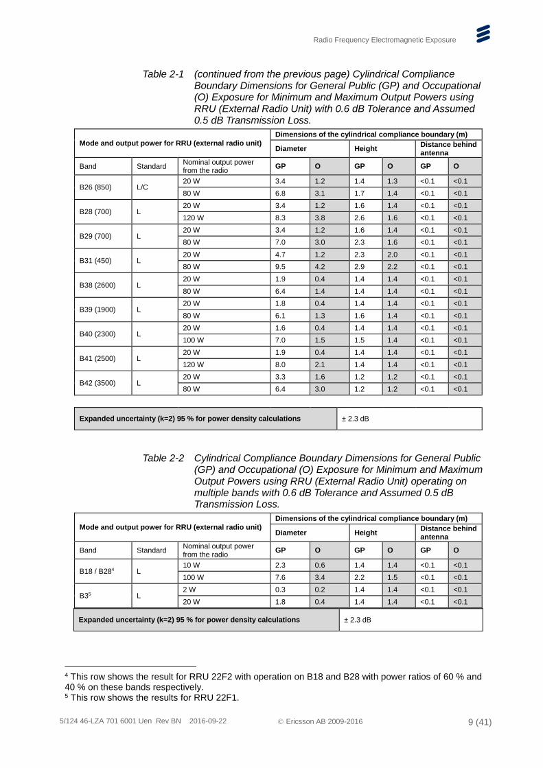
Table 2-1 (continued from the previous page) Cylindrical Compliance Boundary Dimensions for General Public (GP) and Occupational (O) Exposure for Minimum and Maximum Output Powers using RRU (External Radio Unit) with 0.6 dB Tolerance and Assumed 0.5 dB Transmission Loss.
Mode and output power for RRU (external radio unit)
Dimensions of the cylindrical compliance boundary (m)
Diameter Height Distance behind antenna
Band Standard Nominal output power from the radio
GP O GP O GP O
B26 (850) L/C 20 W 3.4 1.2 1.4 1.3 <0.1 <0.1
80 W 6.8 3.1 1.7 1.4 <0.1 <0.1
B28 (700) L 20 W 3.4 1.2 1.6 1.4 <0.1 <0.1
120 W 8.3 3.8 2.6 1.6 <0.1 <0.1
B29 (700) L 20 W 3.4 1.2 1.6 1.4 <0.1 <0.1
80 W 7.0 3.0 2.3 1.6 <0.1 <0.1
B31 (450) L 20 W 4.7 1.2 2.3 2.0 <0.1 <0.1
80 W 9.5 4.2 2.9 2.2 <0.1 <0.1
B38 (2600) L 20 W 1.9 0.4 1.4 1.4 <0.1 <0.1
80 W 6.4 1.4 1.4 1.4 <0.1 <0.1
B39 (1900) L 20 W 1.8 0.4 1.4 1.4 <0.1 <0.1
80 W 6.1 1.3 1.6 1.4 <0.1 <0.1
B40 (2300) L 20 W 1.6 0.4 1.4 1.4 <0.1 <0.1
100 W 7.0 1.5 1.5 1.4 <0.1 <0.1
B41 (2500) L 20 W 1.9 0.4 1.4 1.4 <0.1 <0.1
120 W 8.0 2.1 1.4 1.4 <0.1 <0.1
B42 (3500) L 20 W 3.3 1.6 1.2 1.2 <0.1 <0.1
80 W 6.4 3.0 1.2 1.2 <0.1 <0.1
Expanded uncertainty (k=2) 95 % for power density calculations ± 2.3 dB
Table 2-2 Cylindrical Compliance Boundary Dimensions for General Public (GP) and Occupational (O) Exposure for Minimum and Maximum Output Powers using RRU (External Radio Unit) operating on multiple bands with 0.6 dB Tolerance and Assumed 0.5 dB Transmission Loss.
Mode and output power for RRU (external radio unit)
Dimensions of the cylindrical compliance boundary (m)
Diameter Height Distance behind antenna
Band Standard Nominal output power from the radio
GP O GP O GP O
B18 / B284 L 10 W 2.3 0.6 1.4 1.4 <0.1 <0.1
100 W 7.6 3.4 2.2 1.5 <0.1 <0.1
B35 L 2 W 0.3 0.2 1.4 1.4 <0.1 <0.1
20 W 1.8 0.4 1.4 1.4 <0.1 <0.1
Expanded uncertainty (k=2) 95 % for power density calculations ± 2.3 dB
4 This row shows the result for RRU 22F2 with operation on B18 and B28 with power ratios of 60 % and 40 % on these bands respectively. 5 This row shows the results for RRU 22F1.
Radio Frequency Electromagnetic Exposure
5/124 46-LZA 701 6001 Uen Rev BN 2016-09-22 Ericsson AB 2009-2016 10 (41)
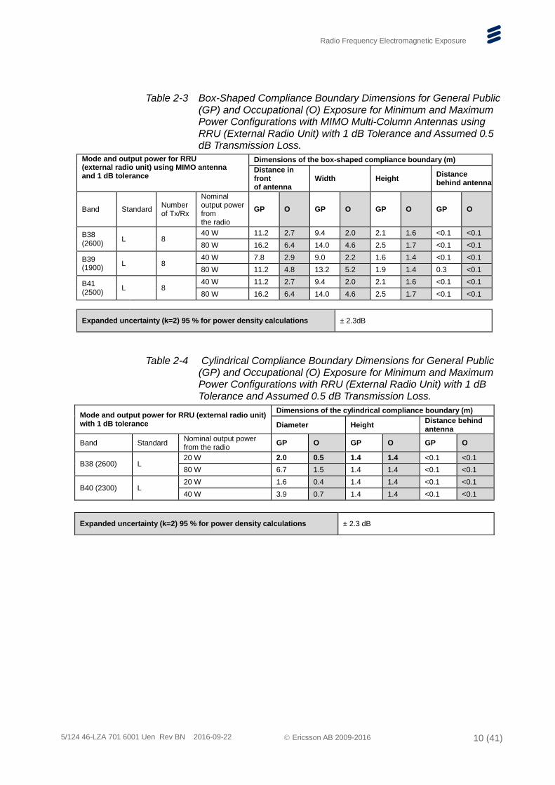
Table 2-3 Box-Shaped Compliance Boundary Dimensions for General Public (GP) and Occupational (O) Exposure for Minimum and Maximum Power Configurations with MIMO Multi-Column Antennas using RRU (External Radio Unit) with 1 dB Tolerance and Assumed 0.5 dB Transmission Loss.
Mode and output power for RRU (external radio unit) using MIMO antenna and 1 dB tolerance
Dimensions of the box-shaped compliance boundary (m)
Distance in front of antenna
Width Height Distance behind antenna
Band Standard Number of Tx/Rx
Nominal output power from the radio
GP O GP O GP O GP O
B38
(2600) L 8
40 W 11.2 2.7 9.4 2.0 2.1 1.6 <0.1 <0.1
80 W 16.2 6.4 14.0 4.6 2.5 1.7 <0.1 <0.1
B39
(1900) L 8
40 W 7.8 2.9 9.0 2.2 1.6 1.4 <0.1 <0.1
80 W 11.2 4.8 13.2 5.2 1.9 1.4 0.3 <0.1
B41
(2500) L 8
40 W 11.2 2.7 9.4 2.0 2.1 1.6 <0.1 <0.1
80 W 16.2 6.4 14.0 4.6 2.5 1.7 <0.1 <0.1
Expanded uncertainty (k=2) 95 % for power density calculations ± 2.3dB
Table 2-4 Cylindrical Compliance Boundary Dimensions for General Public (GP) and Occupational (O) Exposure for Minimum and Maximum Power Configurations with RRU (External Radio Unit) with 1 dB Tolerance and Assumed 0.5 dB Transmission Loss.
Mode and output power for RRU (external radio unit) with 1 dB tolerance
Dimensions of the cylindrical compliance boundary (m)
Diameter Height Distance behind antenna
Band Standard Nominal output power from the radio
GP O GP O GP O
B38 (2600) L 20 W 2.0 0.5 1.4 1.4 <0.1 <0.1
80 W 6.7 1.5 1.4 1.4 <0.1 <0.1
B40 (2300) L 20 W 1.6 0.4 1.4 1.4 <0.1 <0.1
40 W 3.9 0.7 1.4 1.4 <0.1 <0.1
Expanded uncertainty (k=2) 95 % for power density calculations ± 2.3 dB
Radio Frequency Electromagnetic Exposure
5/124 46-LZA 701 6001 Uen Rev BN 2016-09-22 Ericsson AB 2009-2016 11 (41)
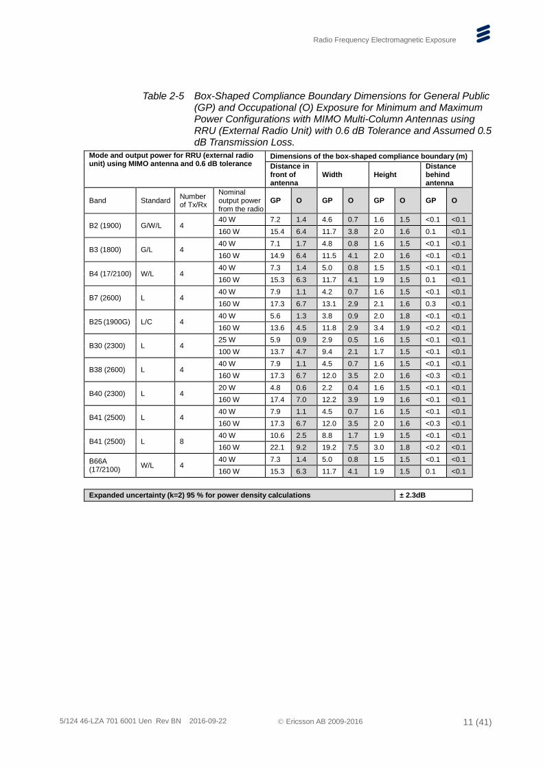
Table 2-5 Box-Shaped Compliance Boundary Dimensions for General Public (GP) and Occupational (O) Exposure for Minimum and Maximum Power Configurations with MIMO Multi-Column Antennas using RRU (External Radio Unit) with 0.6 dB Tolerance and Assumed 0.5 dB Transmission Loss.
Mode and output power for RRU (external radio unit) using MIMO antenna and 0.6 dB tolerance
Dimensions of the box-shaped compliance boundary (m)
Distance in front of antenna
Width Height Distance behind antenna
Band Standard Number of Tx/Rx
Nominal output power from the radio
GP O GP O GP O GP O
B2 (1900) G/W/L 4 40 W 7.2 1.4 4.6 0.7 1.6 1.5 <0.1 <0.1
160 W 15.4 6.4 11.7 3.8 2.0 1.6 0.1 <0.1
B3 (1800) G/L 4 40 W 7.1 1.7 4.8 0.8 1.6 1.5 <0.1 <0.1
160 W 14.9 6.4 11.5 4.1 2.0 1.6 <0.1 <0.1
B4 (17/2100) W/L 4 40 W 7.3 1.4 5.0 0.8 1.5 1.5 <0.1 <0.1
160 W 15.3 6.3 11.7 4.1 1.9 1.5 0.1 <0.1
B7 (2600) L 4 40 W 7.9 1.1 4.2 0.7 1.6 1.5 <0.1 <0.1
160 W 17.3 6.7 13.1 2.9 2.1 1.6 0.3 <0.1
B25 (1900G) L/C 4 40 W 5.6 1.3 3.8 0.9 2.0 1.8 <0.1 <0.1
160 W 13.6 4.5 11.8 2.9 3.4 1.9 <0.2 <0.1
B30 (2300) L 4 25 W 5.9 0.9 2.9 0.5 1.6 1.5 <0.1 <0.1
100 W 13.7 4.7 9.4 2.1 1.7 1.5 <0.1 <0.1
B38 (2600) L 4 40 W 7.9 1.1 4.5 0.7 1.6 1.5 <0.1 <0.1
160 W 17.3 6.7 12.0 3.5 2.0 1.6 <0.3 <0.1
B40 (2300) L 4 20 W 4.8 0.6 2.2 0.4 1.6 1.5 <0.1 <0.1
160 W 17.4 7.0 12.2 3.9 1.9 1.6 <0.1 <0.1
B41 (2500) L 4 40 W 7.9 1.1 4.5 0.7 1.6 1.5 <0.1 <0.1
160 W 17.3 6.7 12.0 3.5 2.0 1.6 <0.3 <0.1
B41 (2500) L 8 40 W 10.6 2.5 8.8 1.7 1.9 1.5 <0.1 <0.1
160 W 22.1 9.2 19.2 7.5 3.0 1.8 <0.2 <0.1
B66A (17/2100)
W/L 4 40 W 7.3 1.4 5.0 0.8 1.5 1.5 <0.1 <0.1
160 W 15.3 6.3 11.7 4.1 1.9 1.5 0.1 <0.1
Expanded uncertainty (k=2) 95 % for power density calculations ± 2.3dB
Radio Frequency Electromagnetic Exposure
5/124 46-LZA 701 6001 Uen Rev BN 2016-09-22 Ericsson AB 2009-2016 12 (41)
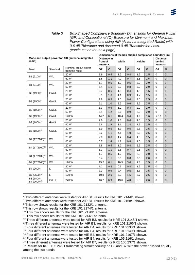
Table 3 Box-Shaped Compliance Boundary Dimensions for General Public (GP) and Occupational (O) Exposure for Minimum and Maximum Power Configurations using AIR (Antenna Integrated Radio) with 0.6 dB Tolerance and Assumed 0 dB Transmission Loss. (continues on the next page)
Mode and output power for AIR (antenna integrated radio)
Dimensions of the box-shaped compliance boundary (m)
Distance in front of antenna
Width Height Distance behind antenna
Band Standard Nominal output power from the radio
GP O GP O GP O GP O
B1 (2100)6 W/L 20 W 1.9 0.5 1.2 0.4 1.5 1.5 0 0
60 W 5.5 1.1 4.0 0.7 1.5 1.5 0 0
B1 (2100)7 W/L 20 W 1.7 0.5 1.2 0.5 2.0 2.0 0 0
60 W 5.4 1.1 3.3 0.8 2.0 2.0 0 0
B2 (1900)8 G/W/L 20 W 2.7 0.6 1.3 0.4 1.5 1.5 0 0
60 W 5.9 1.6 4.1 0.9 1.7 1.5 0 0
B2 (1900)9 G/W/L 20 W 1.8 0.5 1.0 0.4 2.5 2.5 0 0
60 W 5.1 1.0 3.3 0.6 2.6 2.5 0 0
B2 (1900)10 G/W/L 20 W 1.3 0.5 1.2 0.4 2.0 2.0 0 0
60 W 5.4 1.2 3.6 0.9 2.0 2.0 0 0
B2 (1900) 11 G/W/L 120 W 14.2 6.1 10.4 3.4 1.9 1.6 < 0.1 0
B3 (1800)12 G/W/L 20 W 2.6 1.0 1.8 0.6 1.5 1.5 0 0
60 W 5.6 1.9 3.6 1.4 1.5 1.5 0 0
B3 (1800)13 G/W/L 20 W 1.9 0.5 1.3 0.5 2.5 2.5 0 0
60 W 5.2 1.1 4.1 1.0 2.5 2.5 0 0
B4 (17/2100)14 W/L 20 W 2.0 0.6 1.4 0.4 1.5 1.5 0 0
60 W 5.7 1.4 4.2 0.8 1.6 1.5 0 0
B4 (17/2100)15 W/L 20 W 1.8 0.5 1.2 0.4 2.5 2.5 0 0
60 W 5.3 1.1 3.5 0.7 2.6 2.5 0 0
B4 (17/2100)16 W/L 20 W 1.7 0.5 1.2 0.5 2.0 2.0 0 0
60 W 5.4 1.1 3.3 0.8 2.0 2.0 0 0
B4 (17/2100)17 W/L 120 W 15.2 6.1 10.5 3.0 1.8 1.5 0 0
B7 (2600) L 20 W 1.2 0.4 0.9 0.4 1.5 1.5 0 0
60 W 3.3 0.9 2.4 0.5 1.5 1.5 0 0
B7 (2600)18 L 120 W 10.8 2.6 7.0 1.5 5.7 2.5 0 0
B3 (1800), B7 (2600)19
G/L, L 240 W 16.7 6.9 13.6 4.0 5.8 2.6 0 0
6 Two different antennas were tested for AIR B1, results for KRE 101 2144/1 shown. 7 Two different antennas were tested for AIR B1, results for KRE 101 2168/1 shown. 8 This row shows results for the KRE 101 2132/1 antenna. 9 This row shows results for the KRE 101 2174/1 antenna. 10 This row shows results for the KRE 101 2170/1 antenna. 11 This row shows results for the KRE 101 244/1 antenna. 12 Three different antennas were tested for AIR B3, results for KRE 101 2148/1 shown. 13Three different antennas were tested for AIR B3, results for KRE 101 2166/1 shown. 14 Four different antennas were tested for AIR B4, results for KRE 101 2133/1 shown. 15 Four different antennas were tested for AIR B4, results for KRE 101 2149/1 shown. 16 Four different antennas were tested for AIR B4, results for KRE 101 2167/1 shown. 17 Four different antennas were tested for AIR B4, results for KRE 105 216/1 shown. 18 Three different antennas were tested for AIR B7, results for KRE 105 237/1 shown. 19 Results for KRE 105 245/1 transmitting simultaneously on B3 and B7 with the power divided equally among the two bands.
Radio Frequency Electromagnetic Exposure
5/124 46-LZA 701 6001 Uen Rev BN 2016-09-22 Ericsson AB 2009-2016 13 (41)
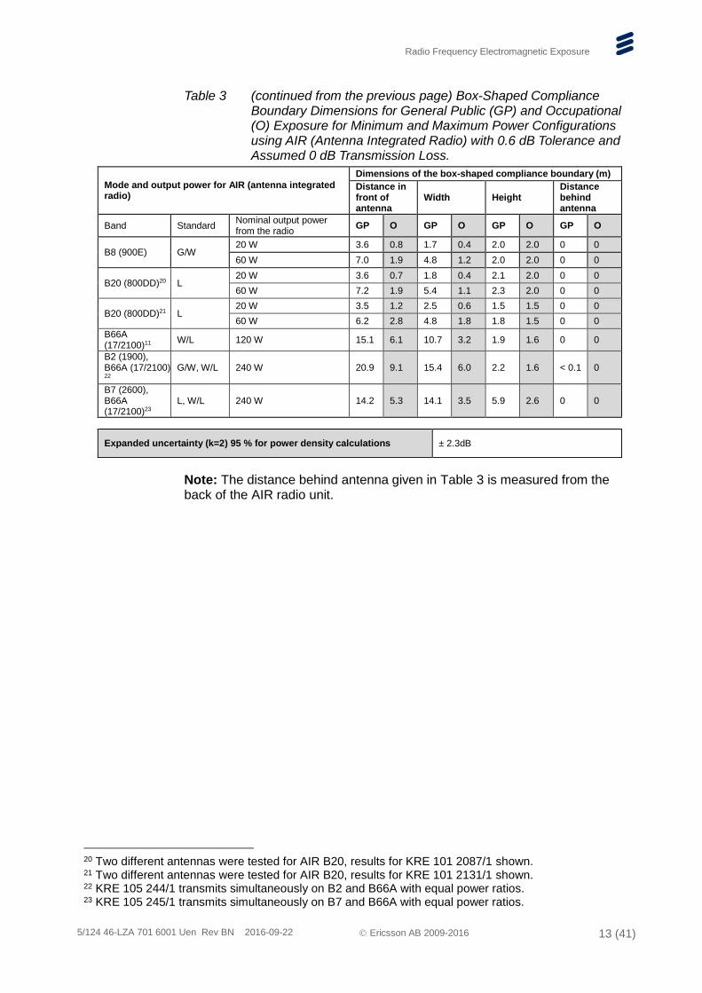
Table 3 (continued from the previous page) Box-Shaped Compliance Boundary Dimensions for General Public (GP) and Occupational (O) Exposure for Minimum and Maximum Power Configurations using AIR (Antenna Integrated Radio) with 0.6 dB Tolerance and Assumed 0 dB Transmission Loss.
Mode and output power for AIR (antenna integrated radio)
Dimensions of the box-shaped compliance boundary (m)
Distance in front of antenna
Width Height Distance behind antenna
Band Standard Nominal output power from the radio
GP O GP O GP O GP O
B8 (900E) G/W 20 W 3.6 0.8 1.7 0.4 2.0 2.0 0 0
60 W 7.0 1.9 4.8 1.2 2.0 2.0 0 0
B20 (800DD)20 L 20 W 3.6 0.7 1.8 0.4 2.1 2.0 0 0
60 W 7.2 1.9 5.4 1.1 2.3 2.0 0 0
B20 (800DD)21 L 20 W 3.5 1.2 2.5 0.6 1.5 1.5 0 0
60 W 6.2 2.8 4.8 1.8 1.8 1.5 0 0
B66A (17/2100)11
W/L 120 W 15.1 6.1 10.7 3.2 1.9 1.6 0 0
B2 (1900), B66A (17/2100)
22 G/W, W/L 240 W 20.9 9.1 15.4 6.0 2.2 1.6 < 0.1 0
B7 (2600), B66A (17/2100)23
L, W/L 240 W 14.2 5.3 14.1 3.5 5.9 2.6 0 0
Expanded uncertainty (k=2) 95 % for power density calculations ± 2.3dB
Note: The distance behind antenna given in Table 3 is measured from the back of the AIR radio unit.
20 Two different antennas were tested for AIR B20, results for KRE 101 2087/1 shown. 21 Two different antennas were tested for AIR B20, results for KRE 101 2131/1 shown. 22 KRE 105 244/1 transmits simultaneously on B2 and B66A with equal power ratios. 23 KRE 105 245/1 transmits simultaneously on B7 and B66A with equal power ratios.
Radio Frequency Electromagnetic Exposure
5/124 46-LZA 701 6001 Uen Rev BN 2016-09-22 Ericsson AB 2009-2016 14 (41)
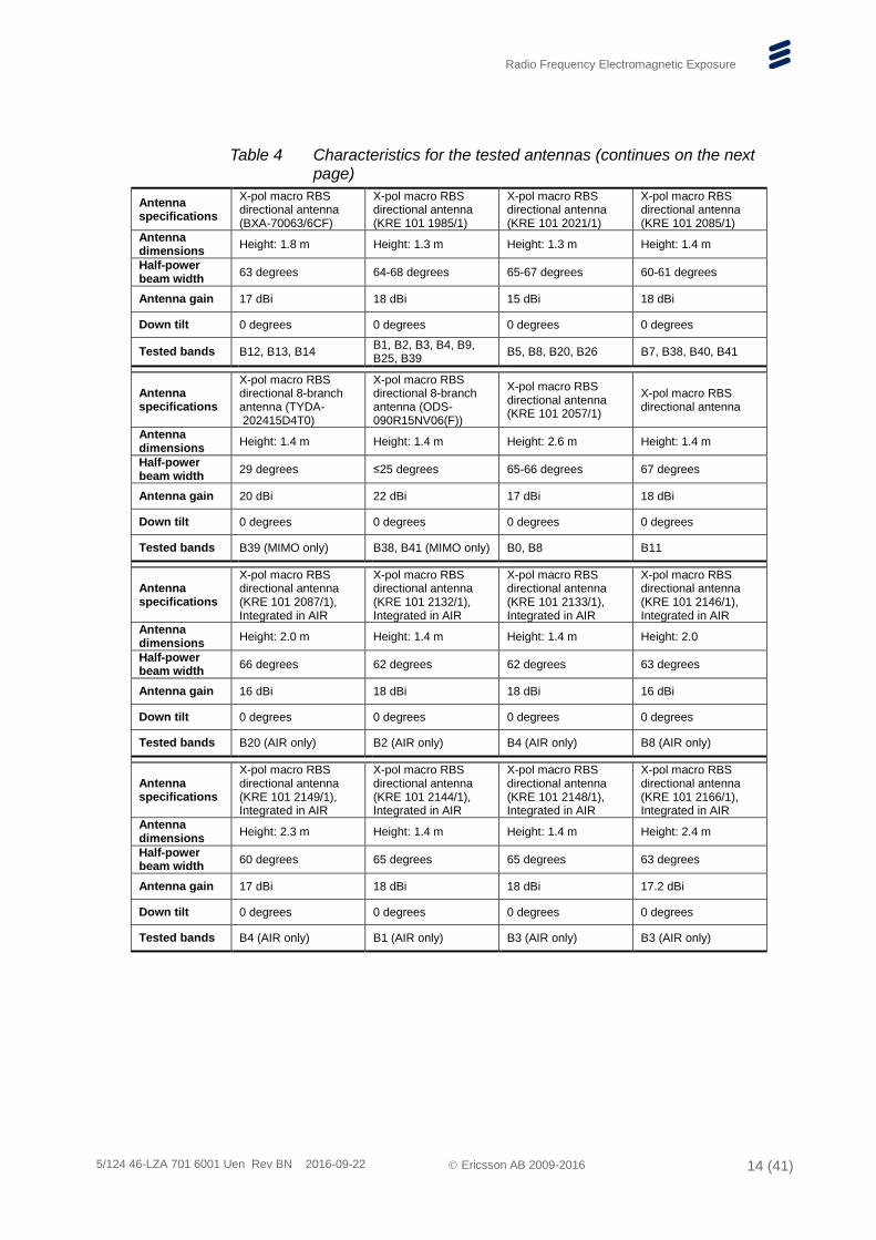
Table 4 Characteristics for the tested antennas (continues on the next page)
Antenna specifications
X-pol macro RBS directional antenna (BXA-70063/6CF)
X-pol macro RBS directional antenna (KRE 101 1985/1)
X-pol macro RBS directional antenna (KRE 101 2021/1)
X-pol macro RBS directional antenna (KRE 101 2085/1)
Antenna dimensions
Height: 1.8 m Height: 1.3 m Height: 1.3 m Height: 1.4 m
Half-power beam width
63 degrees 64-68 degrees 65-67 degrees 60-61 degrees
Antenna gain 17 dBi 18 dBi 15 dBi 18 dBi
Down tilt 0 degrees 0 degrees 0 degrees 0 degrees
Tested bands B12, B13, B14 B1, B2, B3, B4, B9, B25, B39
B5, B8, B20, B26 B7, B38, B40, B41
Antenna specifications
X-pol macro RBS directional 8-branch antenna (TYDA- 202415D4T0)
X-pol macro RBS directional 8-branch antenna (ODS-090R15NV06(F))
X-pol macro RBS directional antenna (KRE 101 2057/1)
X-pol macro RBS directional antenna
Antenna dimensions
Height: 1.4 m Height: 1.4 m Height: 2.6 m Height: 1.4 m
Half-power beam width
29 degrees ≤25 degrees 65-66 degrees 67 degrees
Antenna gain 20 dBi 22 dBi 17 dBi 18 dBi
Down tilt 0 degrees 0 degrees 0 degrees 0 degrees
Tested bands B39 (MIMO only) B38, B41 (MIMO only) B0, B8 B11
Antenna specifications
X-pol macro RBS directional antenna (KRE 101 2087/1), Integrated in AIR
X-pol macro RBS directional antenna (KRE 101 2132/1), Integrated in AIR
X-pol macro RBS directional antenna (KRE 101 2133/1), Integrated in AIR
X-pol macro RBS directional antenna (KRE 101 2146/1), Integrated in AIR
Antenna dimensions
Height: 2.0 m Height: 1.4 m Height: 1.4 m Height: 2.0
Half-power beam width
66 degrees 62 degrees 62 degrees 63 degrees
Antenna gain 16 dBi 18 dBi 18 dBi 16 dBi
Down tilt 0 degrees 0 degrees 0 degrees 0 degrees
Tested bands B20 (AIR only) B2 (AIR only) B4 (AIR only) B8 (AIR only)
Antenna specifications
X-pol macro RBS directional antenna (KRE 101 2149/1), Integrated in AIR
X-pol macro RBS directional antenna (KRE 101 2144/1), Integrated in AIR
X-pol macro RBS directional antenna (KRE 101 2148/1), Integrated in AIR
X-pol macro RBS directional antenna (KRE 101 2166/1), Integrated in AIR
Antenna dimensions
Height: 2.3 m Height: 1.4 m Height: 1.4 m Height: 2.4 m
Half-power beam width
60 degrees 65 degrees 65 degrees 63 degrees
Antenna gain 17 dBi 18 dBi 18 dBi 17.2 dBi
Down tilt 0 degrees 0 degrees 0 degrees 0 degrees
Tested bands B4 (AIR only) B1 (AIR only) B3 (AIR only) B3 (AIR only)
Radio Frequency Electromagnetic Exposure
5/124 46-LZA 701 6001 Uen Rev BN 2016-09-22 Ericsson AB 2009-2016 15 (41)
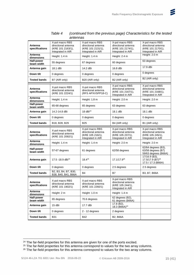
Table 4 (continued from the previous page) Characteristics for the tested antennas
Antenna specifications
X-pol macro RBS directional antenna (KRE 101 2163/1), Integrated in AIR
X-pol macro RBS directional antenna (KRE 101 2131/1), Integrated in AIR
X-pol macro RBS directional antenna (KRE 101 2174/1), Integrated in AIR
X-pol macro RBS directional antenna (KRE 101 2170/1), Integrated in AIR
Antenna dimensions
Height: 1.4 m Height: 1.4 m Height: 2.4 m Height: 2.0 m
Half-power beam width
55 degrees 67 degrees 60 degrees 63 degrees
Antenna gain 18.1 dBi 14.2 dBi 16.8 dBi 17.9 dBi
Down tilt 0 degrees 0 degrees 0 degrees 0 degrees
Tested bands B7 (AIR only) B20 (AIR only) B2 (AIR only) B2 (AIR only)
Antenna specifications
X-pol macro RBS directional antenna (KRE 101 2224/1)
X-pol macro RBS directional antenna (RFS APXVSPP18-C)
X-pol macro RBS directional antenna (KRE 101 2167/1), Integrated in AIR
X-pol macro RBS directional antenna (KRE 101 2168/1), Integrated in AIR
Antenna dimensions
Height: 1.4 m Height: 1.8 m Height: 2.0 m Height: 2.0 m
Half-power beam width
65-68 degrees 65 degrees 63 degrees 63 degrees
Antenna gain 14.2-14.8 dBi 18 dBi24 18.1 dBi 18.1 dBi
Down tilt 0 degrees 0 degrees 0 degrees 0 degrees
Tested bands B18, B28, B29 B25 B4 (AIR only) B1 (AIR only)
Antenna specifications
X-pol macro RBS directional antenna (KRE 101 2092/1)
X-pol macro RBS directional antenna (KRE 105 216/1), Integrated in AIR
X-pol macro RBS directional antenna (KRE 105 237/1), Integrated in AIR
X-pol macro RBS directional antenna (KRE 105 245/1), Integrated in AIR
Antenna dimensions
Height: 1.4 m Height: 1.4 m Height: 2.0 m Height: 2.0 m
Half-power beam width
57-67 degrees 61 degrees 62/58 degrees 62/64 degrees (B3), 63/58 degrees (B7) 59/63 degrees (B66A)
Antenna gain 17.5 -18.9 dBi24 18.424 17.1/17.925 17/16.9 (B3), 17.5/17.9 (B7)26 17.5 / 17.3 (B66A)
Down tilt 0 degrees 0 degrees 2.5 degrees 2.5 degrees
Tested bands B2, B3, B4, B7, B30, B38, B40, B41, B66A
B4 B7 B3, B7, B66A
Antenna specifications
X-pol macro RBS directional antenna (KRE 101 1902/1)
X-pol macro RBS directional antenna (KRE 101 2260/1)
X-pol macro RBS directional antenna (KRE 105 244/1), Integrated in AIR
Antenna dimensions
Height: 2 m Height: 1.0 m Height: 1.4 m
Half-power beam width
65 degrees 70.6 degrees 62 degrees (B2), 61 degrees (B66A)
Antenna gain 15 dBi 17.7 dBi 17.8 (B2), 18.3 (B66A)24
Down tilt 0 degrees 2 - 12 degrees 2 degrees
Tested bands B31 B42 B2, B66A
24 The far-field properties for this antenna are given for one of the ports excited. 25 The far-field properties for this antenna correspond to values for the two array columns. 26 The far-field properties for this antenna correspond to values for the two array columns.
Radio Frequency Electromagnetic Exposure
5/124 46-LZA 701 6001 Uen Rev BN 2016-09-22 Ericsson AB 2009-2016 16 (41)
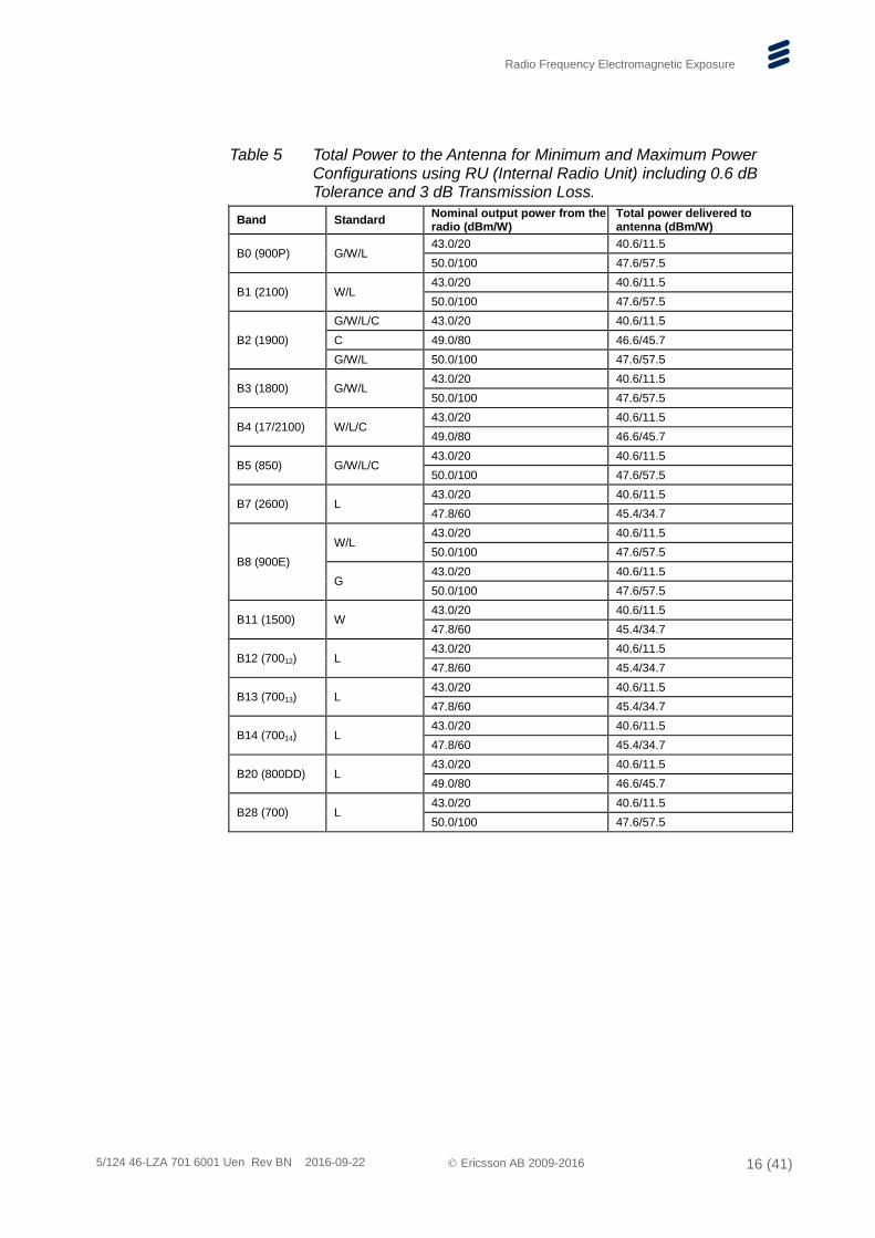
Table 5 Total Power to the Antenna for Minimum and Maximum Power Configurations using RU (Internal Radio Unit) including 0.6 dB Tolerance and 3 dB Transmission Loss.
Band Standard Nominal output power from the radio (dBm/W)
Total power delivered to antenna (dBm/W)
B0 (900P) G/W/L 43.0/20 40.6/11.5
50.0/100 47.6/57.5
B1 (2100) W/L 43.0/20 40.6/11.5
50.0/100 47.6/57.5
B2 (1900)
G/W/L/C 43.0/20 40.6/11.5
C 49.0/80 46.6/45.7
G/W/L 50.0/100 47.6/57.5
B3 (1800) G/W/L 43.0/20 40.6/11.5
50.0/100 47.6/57.5
B4 (17/2100) W/L/C 43.0/20 40.6/11.5
49.0/80 46.6/45.7
B5 (850) G/W/L/C 43.0/20 40.6/11.5
50.0/100 47.6/57.5
B7 (2600) L 43.0/20 40.6/11.5
47.8/60 45.4/34.7
B8 (900E)
W/L 43.0/20 40.6/11.5
50.0/100 47.6/57.5
G 43.0/20 40.6/11.5
50.0/100 47.6/57.5
B11 (1500) W 43.0/20 40.6/11.5
47.8/60 45.4/34.7
B12 (70012) L 43.0/20 40.6/11.5
47.8/60 45.4/34.7
B13 (70013) L 43.0/20 40.6/11.5
47.8/60 45.4/34.7
B14 (70014) L 43.0/20 40.6/11.5
47.8/60 45.4/34.7
B20 (800DD) L 43.0/20 40.6/11.5
49.0/80 46.6/45.7
B28 (700) L 43.0/20 40.6/11.5
50.0/100 47.6/57.5
Radio Frequency Electromagnetic Exposure
5/124 46-LZA 701 6001 Uen Rev BN 2016-09-22 Ericsson AB 2009-2016 17 (41)
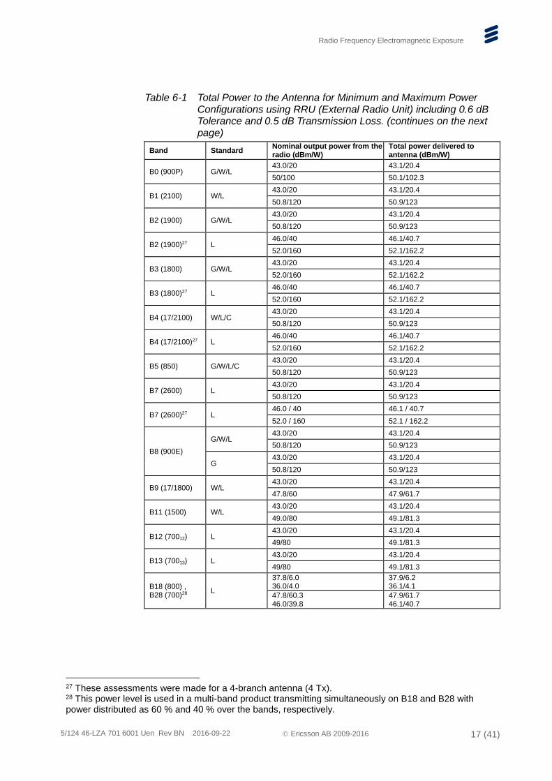
Table 6-1 Total Power to the Antenna for Minimum and Maximum Power Configurations using RRU (External Radio Unit) including 0.6 dB Tolerance and 0.5 dB Transmission Loss. (continues on the next page)
Band Standard Nominal output power from the radio (dBm/W)
Total power delivered to antenna (dBm/W)
B0 (900P) G/W/L 43.0/20 43.1/20.4
50/100 50.1/102.3
B1 (2100) W/L 43.0/20 43.1/20.4
50.8/120 50.9/123
B2 (1900) G/W/L 43.0/20 43.1/20.4
50.8/120 50.9/123
B2 (1900)27 L 46.0/40 46.1/40.7
52.0/160 52.1/162.2
B3 (1800) G/W/L 43.0/20 43.1/20.4
52.0/160 52.1/162.2
B3 (1800)27 L 46.0/40 46.1/40.7
52.0/160 52.1/162.2
B4 (17/2100) W/L/C 43.0/20 43.1/20.4
50.8/120 50.9/123
B4 (17/2100)27 L 46.0/40 46.1/40.7
52.0/160 52.1/162.2
B5 (850) G/W/L/C 43.0/20 43.1/20.4
50.8/120 50.9/123
B7 (2600) L 43.0/20 43.1/20.4
50.8/120 50.9/123
B7 (2600)27 L 46.0 / 40 46.1 / 40.7
52.0 / 160 52.1 / 162.2
B8 (900E)
G/W/L 43.0/20 43.1/20.4
50.8/120 50.9/123
G 43.0/20 43.1/20.4
50.8/120 50.9/123
B9 (17/1800) W/L 43.0/20 43.1/20.4
47.8/60 47.9/61.7
B11 (1500) W/L 43.0/20 43.1/20.4
49.0/80 49.1/81.3
B12 (70012) L 43.0/20 43.1/20.4
49/80 49.1/81.3
B13 (70013) L 43.0/20 43.1/20.4
49/80 49.1/81.3
B18 (800) , B28 (700)28
L
37.8/6.0 36.0/4.0
37.9/6.2 36.1/4.1
47.8/60.3 46.0/39.8
47.9/61.7 46.1/40.7
27 These assessments were made for a 4-branch antenna (4 Tx). 28 This power level is used in a multi-band product transmitting simultaneously on B18 and B28 with power distributed as 60 % and 40 % over the bands, respectively.
Radio Frequency Electromagnetic Exposure
5/124 46-LZA 701 6001 Uen Rev BN 2016-09-22 Ericsson AB 2009-2016 18 (41)
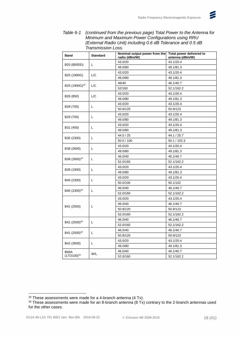
Table 6-1 (continued from the previous page) Total Power to the Antenna for Minimum and Maximum Power Configurations using RRU (External Radio Unit) including 0.6 dB Tolerance and 0.5 dB Transmission Loss.
Band Standard Nominal output power from the radio (dBm/W)
Total power delivered to antenna (dBm/W)
B20 (800DD) L 43.0/20 43.1/20.4
49.0/80 49.1/81.3
B25 (1900G) L/C 43.0/20 43.1/20.4
49.0/80 49.1/81.3
B25 (1900G)29 L/C 46/40 46.1/40.7
52/160 52.1/162.2
B26 (850) L/C 43.0/20 43.1/20.4
49.0/80 49.1/81.3
B28 (700) L 43.0/20 43.1/20.4
50.8/120 50.9/123
B29 (700) L 43.0/20 43.1/20.4
49.0/80 49.1/81.3
B31 (450) L 43.0/20 43.1/20.4
49.0/80 49.1/81.3
B30 (2300) L 44.0 / 25 44.1 / 25.7
50.0 / 100 50.1 / 102.3
B38 (2600) L 43.0/20 43.1/20.4
49.0/80 49.1/81.3
B38 (2600)29 L 46.0/40 46.1/40.7
52.0/160 52.1/162.2
B39 (1900) L 43.0/20 43.1/20.4
49.0/80 49.1/81.3
B40 (2300) L 43.0/20 43.1/20.4
50.0/100 50.1/102
B40 (2300)29 L 46.0/40 46.1/40.7
52.0/160 52.1/162.2
B41 (2500) L
43.0/20 43.1/20.4
46.0/40 46.1/40.7
50.8/120 50.9/123
52.0/160 52.1/162.2
B41 (2500)29 L 46.0/40 46.1/40.7
52.0/160 52.1/162.2
B41 (2500)30 L 46.0/40 46.1/40.7
50.8/120 50.9/123
B42 (3500) L 43.0/20 43.1/20.4
49.0/80 49.1/81.3
B66A (17/2100)29
W/L 46.0/40 46.1/40.7
52.0/160 52.1/162.2
29 These assessments were made for a 4-branch antenna (4 Tx). 30 These assessments were made for an 8-branch antenna (8 Tx) contrary to the 2-branch antennas used for the other cases.
Radio Frequency Electromagnetic Exposure
5/124 46-LZA 701 6001 Uen Rev BN 2016-09-22 Ericsson AB 2009-2016 19 (41)
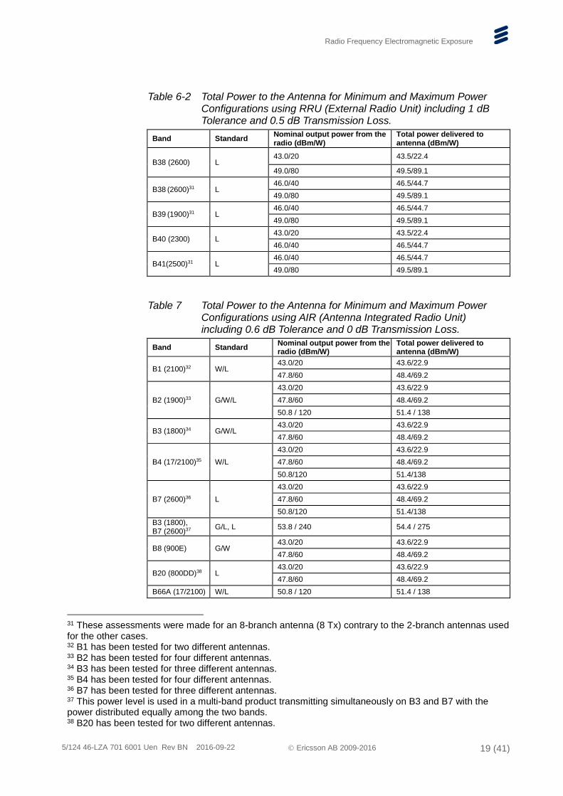
Table 6-2 Total Power to the Antenna for Minimum and Maximum Power Configurations using RRU (External Radio Unit) including 1 dB Tolerance and 0.5 dB Transmission Loss.
Band Standard Nominal output power from the radio (dBm/W)
Total power delivered to antenna (dBm/W)
B38 (2600) L 43.0/20 43.5/22.4
49.0/80 49.5/89.1
B38 (2600)31 L 46.0/40 46.5/44.7
49.0/80 49.5/89.1
B39 (1900)31 L 46.0/40 46.5/44.7
49.0/80 49.5/89.1
B40 (2300) L 43.0/20 43.5/22.4
46.0/40 46.5/44.7
B41(2500)31 L 46.0/40 46.5/44.7
49.0/80 49.5/89.1
Table 7 Total Power to the Antenna for Minimum and Maximum Power Configurations using AIR (Antenna Integrated Radio Unit) including 0.6 dB Tolerance and 0 dB Transmission Loss.
Band Standard Nominal output power from the radio (dBm/W)
Total power delivered to antenna (dBm/W)
B1 (2100)32 W/L 43.0/20 43.6/22.9
47.8/60 48.4/69.2
B2 (1900)33 G/W/L
43.0/20 43.6/22.9
47.8/60 48.4/69.2
50.8 / 120 51.4 / 138
B3 (1800)34 G/W/L 43.0/20 43.6/22.9
47.8/60 48.4/69.2
B4 (17/2100)35 W/L
43.0/20 43.6/22.9
47.8/60 48.4/69.2
50.8/120 51.4/138
B7 (2600)36 L
43.0/20 43.6/22.9
47.8/60 48.4/69.2
50.8/120 51.4/138
B3 (1800), B7 (2600)37
G/L, L 53.8 / 240 54.4 / 275
B8 (900E) G/W 43.0/20 43.6/22.9
47.8/60 48.4/69.2
B20 (800DD)38 L 43.0/20 43.6/22.9
47.8/60 48.4/69.2
B66A (17/2100) W/L 50.8 / 120 51.4 / 138
31 These assessments were made for an 8-branch antenna (8 Tx) contrary to the 2-branch antennas used for the other cases. 32 B1 has been tested for two different antennas. 33 B2 has been tested for four different antennas. 34 B3 has been tested for three different antennas. 35 B4 has been tested for four different antennas. 36 B7 has been tested for three different antennas. 37 This power level is used in a multi-band product transmitting simultaneously on B3 and B7 with the power distributed equally among the two bands. 38 B20 has been tested for two different antennas.
Radio Frequency Electromagnetic Exposure
5/124 46-LZA 701 6001 Uen Rev BN 2016-09-22 Ericsson AB 2009-2016 20 (41)
Band Standard Nominal output power from the radio (dBm/W)
Total power delivered to antenna (dBm/W)
B2 (1900), B66A (17/2100) 39
G/W, W/L 53.8 / 240 54.4 / 275
B3 (1800), B7 (2600)40
L, W/L 53.8 / 240 54.4 / 275
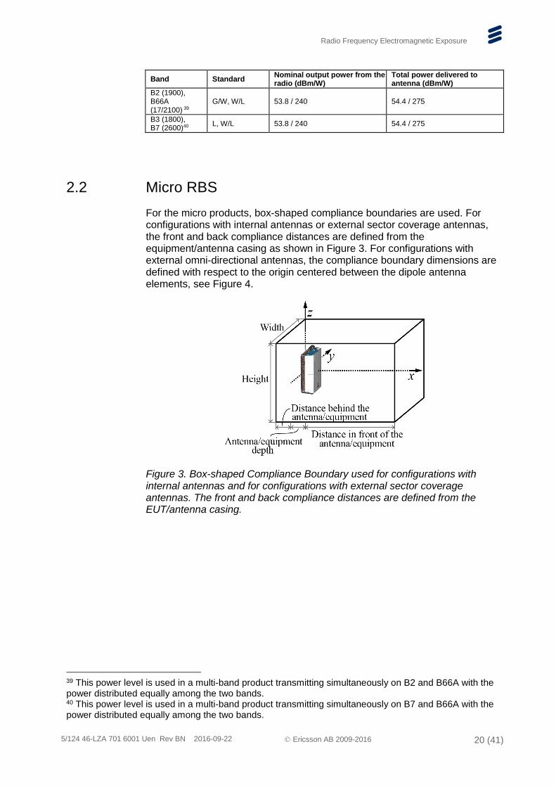
2.2 Micro RBS
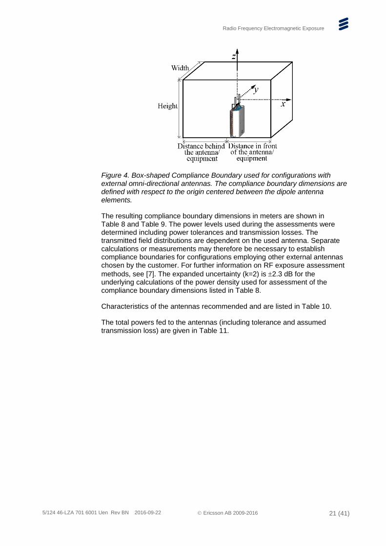
For the micro products, box-shaped compliance boundaries are used. For configurations with internal antennas or external sector coverage antennas, the front and back compliance distances are defined from the equipment/antenna casing as shown in Figure 3. For configurations with external omni-directional antennas, the compliance boundary dimensions are defined with respect to the origin centered between the dipole antenna elements, see Figure 4.
Figure 3. Box-shaped Compliance Boundary used for configurations with internal antennas and for configurations with external sector coverage antennas. The front and back compliance distances are defined from the EUT/antenna casing.
39 This power level is used in a multi-band product transmitting simultaneously on B2 and B66A with the power distributed equally among the two bands. 40 This power level is used in a multi-band product transmitting simultaneously on B7 and B66A with the power distributed equally among the two bands.
Radio Frequency Electromagnetic Exposure
5/124 46-LZA 701 6001 Uen Rev BN 2016-09-22 Ericsson AB 2009-2016 21 (41)
Figure 4. Box-shaped Compliance Boundary used for configurations with external omni-directional antennas. The compliance boundary dimensions are defined with respect to the origin centered between the dipole antenna elements.
The resulting compliance boundary dimensions in meters are shown in Table 8 and Table 9. The power levels used during the assessments were determined including power tolerances and transmission losses. The transmitted field distributions are dependent on the used antenna. Separate calculations or measurements may therefore be necessary to establish compliance boundaries for configurations employing other external antennas chosen by the customer. For further information on RF exposure assessment
methods, see [7]. The expanded uncertainty (k=2) is 2.3 dB for the underlying calculations of the power density used for assessment of the compliance boundary dimensions listed in Table 8.
Characteristics of the antennas recommended and are listed in Table 10.
The total powers fed to the antennas (including tolerance and assumed transmission loss) are given in Table 11.
Radio Frequency Electromagnetic Exposure
5/124 46-LZA 701 6001 Uen Rev BN 2016-09-22 Ericsson AB 2009-2016 22 (41)
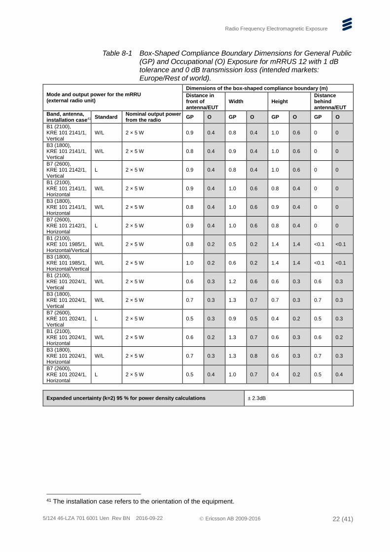
Table 8-1 Box-Shaped Compliance Boundary Dimensions for General Public (GP) and Occupational (O) Exposure for mRRUS 12 with 1 dB tolerance and 0 dB transmission loss (intended markets: Europe/Rest of world).
Mode and output power for the mRRU (external radio unit)
Dimensions of the box-shaped compliance boundary (m)
Distance in front of antenna/EUT
Width Height Distance behind antenna/EUT
Band, antenna, installation case41
Standard Nominal output power from the radio
GP O GP O GP O GP O
B1 (2100), KRE 101 2141/1, Vertical
W/L 2 × 5 W 0.9 0.4 0.8 0.4 1.0 0.6 0 0
B3 (1800), KRE 101 2141/1, Vertical
W/L 2 × 5 W 0.8 0.4 0.9 0.4 1.0 0.6 0 0
B7 (2600), KRE 101 2142/1, Vertical
L 2 × 5 W 0.9 0.4 0.8 0.4 1.0 0.6 0 0
B1 (2100), KRE 101 2141/1, Horizontal
W/L 2 × 5 W 0.9 0.4 1.0 0.6 0.8 0.4 0 0
B3 (1800), KRE 101 2141/1, Horizontal
W/L 2 × 5 W 0.8 0.4 1.0 0.6 0.9 0.4 0 0
B7 (2600), KRE 101 2142/1, Horizontal
L 2 × 5 W 0.9 0.4 1.0 0.6 0.8 0.4 0 0
B1 (2100), KRE 101 1985/1, Horizontal/Vertical
W/L 2 × 5 W 0.8 0.2 0.5 0.2 1.4 1.4 <0.1 <0.1
B3 (1800), KRE 101 1985/1, Horizontal/Vertical
W/L 2 × 5 W 1.0 0.2 0.6 0.2 1.4 1.4 <0.1 <0.1
B1 (2100), KRE 101 2024/1, Vertical
W/L 2 × 5 W 0.6 0.3 1.2 0.6 0.6 0.3 0.6 0.3
B3 (1800), KRE 101 2024/1, Vertical
W/L 2 × 5 W 0.7 0.3 1.3 0.7 0.7 0.3 0.7 0.3
B7 (2600), KRE 101 2024/1, Vertical
L 2 × 5 W 0.5 0.3 0.9 0.5 0.4 0.2 0.5 0.3
B1 (2100), KRE 101 2024/1, Horizontal
W/L 2 × 5 W 0.6 0.2 1.3 0.7 0.6 0.3 0.6 0.2
B3 (1800), KRE 101 2024/1, Horizontal
W/L 2 × 5 W 0.7 0.3 1.3 0.8 0.6 0.3 0.7 0.3
B7 (2600), KRE 101 2024/1, Horizontal
L 2 × 5 W 0.5 0.4 1.0 0.7 0.4 0.2 0.5 0.4
Expanded uncertainty (k=2) 95 % for power density calculations ± 2.3dB
41 The installation case refers to the orientation of the equipment.
Radio Frequency Electromagnetic Exposure
5/124 46-LZA 701 6001 Uen Rev BN 2016-09-22 Ericsson AB 2009-2016 23 (41)
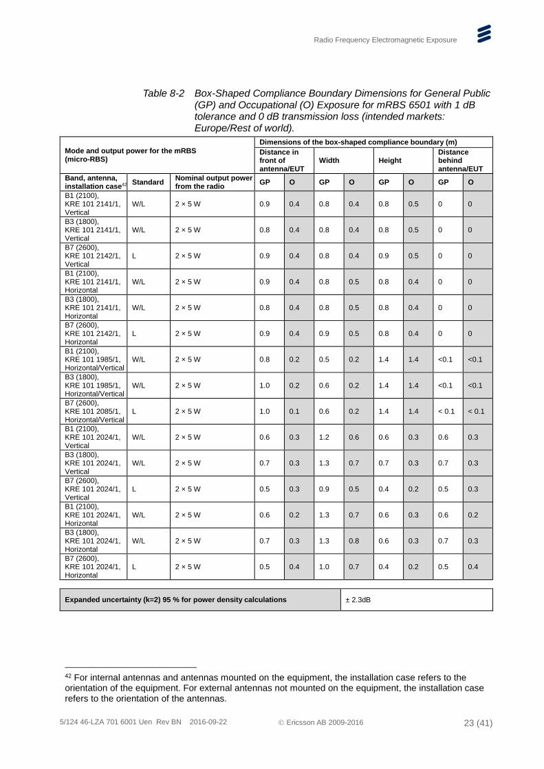
Table 8-2 Box-Shaped Compliance Boundary Dimensions for General Public (GP) and Occupational (O) Exposure for mRBS 6501 with 1 dB tolerance and 0 dB transmission loss (intended markets: Europe/Rest of world).
Mode and output power for the mRBS (micro-RBS)
Dimensions of the box-shaped compliance boundary (m)
Distance in front of antenna/EUT
Width Height Distance behind antenna/EUT
Band, antenna, installation case42
Standard Nominal output power from the radio
GP O GP O GP O GP O
B1 (2100), KRE 101 2141/1, Vertical
W/L 2 × 5 W 0.9 0.4 0.8 0.4 0.8 0.5 0 0
B3 (1800), KRE 101 2141/1, Vertical
W/L 2 × 5 W 0.8 0.4 0.8 0.4 0.8 0.5 0 0
B7 (2600), KRE 101 2142/1, Vertical
L 2 × 5 W 0.9 0.4 0.8 0.4 0.9 0.5 0 0
B1 (2100), KRE 101 2141/1, Horizontal
W/L 2 × 5 W 0.9 0.4 0.8 0.5 0.8 0.4 0 0
B3 (1800), KRE 101 2141/1, Horizontal
W/L 2 × 5 W 0.8 0.4 0.8 0.5 0.8 0.4 0 0
B7 (2600), KRE 101 2142/1, Horizontal
L 2 × 5 W 0.9 0.4 0.9 0.5 0.8 0.4 0 0
B1 (2100), KRE 101 1985/1, Horizontal/Vertical
W/L 2 × 5 W 0.8 0.2 0.5 0.2 1.4 1.4 <0.1 <0.1
B3 (1800), KRE 101 1985/1, Horizontal/Vertical
W/L 2 × 5 W 1.0 0.2 0.6 0.2 1.4 1.4 <0.1 <0.1
B7 (2600), KRE 101 2085/1, Horizontal/Vertical
L 2 × 5 W 1.0 0.1 0.6 0.2 1.4 1.4 < 0.1 < 0.1
B1 (2100), KRE 101 2024/1, Vertical
W/L 2 × 5 W 0.6 0.3 1.2 0.6 0.6 0.3 0.6 0.3
B3 (1800), KRE 101 2024/1, Vertical
W/L 2 × 5 W 0.7 0.3 1.3 0.7 0.7 0.3 0.7 0.3
B7 (2600), KRE 101 2024/1, Vertical
L 2 × 5 W 0.5 0.3 0.9 0.5 0.4 0.2 0.5 0.3
B1 (2100), KRE 101 2024/1, Horizontal
W/L 2 × 5 W 0.6 0.2 1.3 0.7 0.6 0.3 0.6 0.2
B3 (1800), KRE 101 2024/1, Horizontal
W/L 2 × 5 W 0.7 0.3 1.3 0.8 0.6 0.3 0.7 0.3
B7 (2600), KRE 101 2024/1, Horizontal
L 2 × 5 W 0.5 0.4 1.0 0.7 0.4 0.2 0.5 0.4
Expanded uncertainty (k=2) 95 % for power density calculations ± 2.3dB
42 For internal antennas and antennas mounted on the equipment, the installation case refers to the orientation of the equipment. For external antennas not mounted on the equipment, the installation case refers to the orientation of the antennas.
Radio Frequency Electromagnetic Exposure
5/124 46-LZA 701 6001 Uen Rev BN 2016-09-22 Ericsson AB 2009-2016 24 (41)
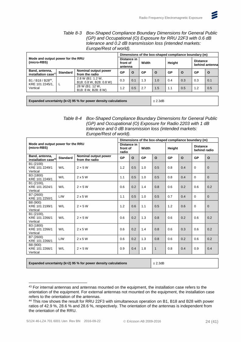
Table 8-3 Box-Shaped Compliance Boundary Dimensions for General Public (GP) and Occupational (O) Exposure for RRU 22F3 with 0.6 dB tolerance and 0.2 dB transmission loss (intended markets: Europe/Rest of world).
Mode and output power for the RRU (micro-RBS)
Dimensions of the box-shaped compliance boundary (m)
Distance in front of antenna
Width Height Distance behind antenna
Band, antenna, installation case43
Standard Nominal output power from the radio
GP O GP O GP O GP O
B1 / B18 / B2844, KRE 101 2245/1, Vertical
L
2.8 W (B1: 1.2 W, B18: 0.8 W, B28: 0.8 W)
0.3 0.1 1.3 1.0 0.4 0.3 0.3 0.1
28 W (B1: 12 W, B18: 8 W, B28: 8 W)
1.2 0.5 2.7 1.5 1.1 0.5 1.2 0.5
Expanded uncertainty (k=2) 95 % for power density calculations ± 2.3dB
Table 8-4 Box-Shaped Compliance Boundary Dimensions for General Public (GP) and Occupational (O) Exposure for Radio 2203 with 1 dB tolerance and 0 dB transmission loss (intended markets: Europe/Rest of world).
Mode and output power for the RRU (micro-RBS)
Dimensions of the box-shaped compliance boundary (m)
Distance in front of radio
Width Height Distance behind radio
Band, antenna, installation case43
Standard Nominal output power from the radio
GP O GP O GP O GP O
B1 (2100) KRE 101 2249/1 Vertical
W/L 2 × 5 W 1.2 0.5 1.0 0.5 0.8 0.4 0 0
B3 (1800) KRE 101 2249/1
W/L 2 x 5 W 1.1 0.5 1.0 0.5 0.8 0.4 0 0
B1 (2100), KRE 101 2024/1 Vertical
W/L 2 × 5 W 0.6 0.2 1.4 0.8 0.6 0.2 0.6 0.2
B7 (2600) KRE 101 2250/1
L/W 2 x 5 W 1.1 0.5 1.0 0.5 0.7 0.4 0 0
B8 (900) KRE 101 2199/1 Vertical
W/L 2 × 5 W 1.2 0.6 1.1 0.5 1.2 0.6 0 0
B1 (2100), KRE 101 2266/1 Vertical
W/L 2 × 5 W 0.6 0.2 1.3 0.8 0.6 0.2 0.6 0.2
B3 (1800) KRE 101 2266/1 Vertical
W/L 2 x 5 W 0.6 0.2 1.4 0.8 0.6 0.3 0.6 0.2
B7 (2600) KRE 101 2266/1
L/W 2 x 5 W 0.6 0.2 1.3 0.8 0.6 0.2 0.6 0.2
B8 (900) KRE 101 2266/1 Vertical
W/L 2 × 5 W 0.9 0.4 1.8 1 0.8 0.4 0.9 0.4
Expanded uncertainty (k=2) 95 % for power density calculations ± 2.3dB
43 For internal antennas and antennas mounted on the equipment, the installation case refers to the orientation of the equipment. For external antennas not mounted on the equipment, the installation case refers to the orientation of the antennas. 44 This row shows the result for RRU 22F3 with simultaneous operation on B1, B18 and B28 with power ratios of 42.9 %, 28.6 % and 28.6 %, respectively. The orientation of the antennas is independent from the orientation of the RRU.
Radio Frequency Electromagnetic Exposure
5/124 46-LZA 701 6001 Uen Rev BN 2016-09-22 Ericsson AB 2009-2016 25 (41)
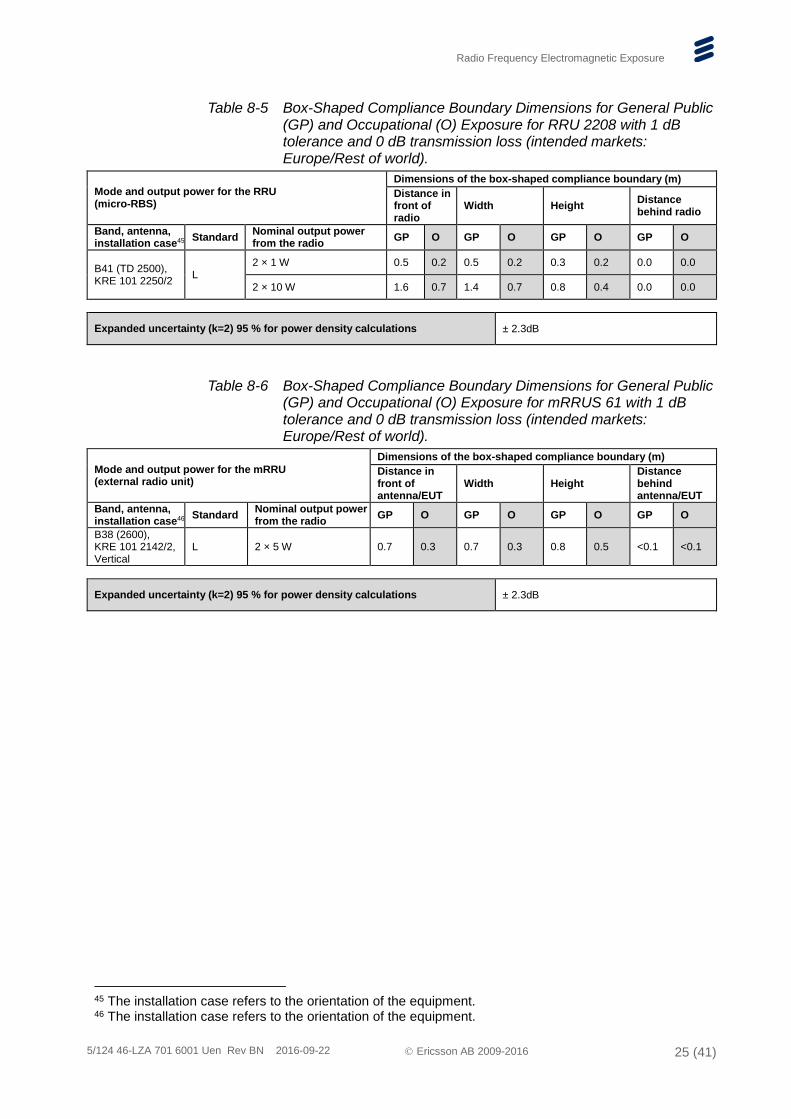
Table 8-5 Box-Shaped Compliance Boundary Dimensions for General Public (GP) and Occupational (O) Exposure for RRU 2208 with 1 dB tolerance and 0 dB transmission loss (intended markets: Europe/Rest of world).
Mode and output power for the RRU (micro-RBS)
Dimensions of the box-shaped compliance boundary (m)
Distance in front of radio
Width Height Distance behind radio
Band, antenna, installation case45
Standard Nominal output power from the radio
GP O GP O GP O GP O
B41 (TD 2500), KRE 101 2250/2
L 2 × 1 W 0.5 0.2 0.5 0.2 0.3 0.2 0.0 0.0
2 × 10 W 1.6 0.7 1.4 0.7 0.8 0.4 0.0 0.0
Expanded uncertainty (k=2) 95 % for power density calculations ± 2.3dB
Table 8-6 Box-Shaped Compliance Boundary Dimensions for General Public (GP) and Occupational (O) Exposure for mRRUS 61 with 1 dB tolerance and 0 dB transmission loss (intended markets: Europe/Rest of world).
Mode and output power for the mRRU (external radio unit)
Dimensions of the box-shaped compliance boundary (m)
Distance in front of antenna/EUT
Width Height Distance behind antenna/EUT
Band, antenna, installation case46
Standard Nominal output power from the radio
GP O GP O GP O GP O
B38 (2600), KRE 101 2142/2, Vertical
L 2 × 5 W 0.7 0.3 0.7 0.3 0.8 0.5 <0.1 <0.1
Expanded uncertainty (k=2) 95 % for power density calculations ± 2.3dB
45 The installation case refers to the orientation of the equipment. 46 The installation case refers to the orientation of the equipment.
Radio Frequency Electromagnetic Exposure
5/124 46-LZA 701 6001 Uen Rev BN 2016-09-22 Ericsson AB 2009-2016 26 (41)
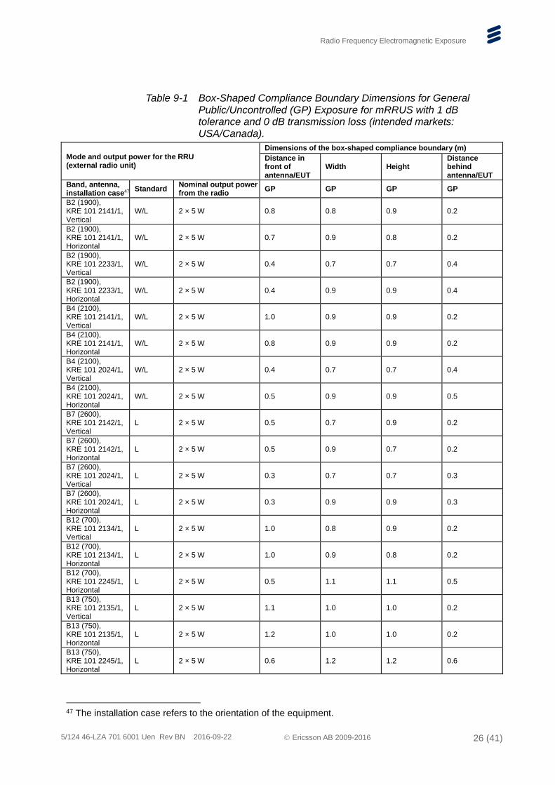
Table 9-1 Box-Shaped Compliance Boundary Dimensions for General Public/Uncontrolled (GP) Exposure for mRRUS with 1 dB tolerance and 0 dB transmission loss (intended markets: USA/Canada).
Mode and output power for the RRU (external radio unit)
Dimensions of the box-shaped compliance boundary (m)
Distance in front of antenna/EUT
Width Height Distance behind antenna/EUT
Band, antenna, installation case47
Standard Nominal output power from the radio
GP GP GP GP
B2 (1900), KRE 101 2141/1, Vertical
W/L 2 × 5 W 0.8 0.8 0.9 0.2
B2 (1900), KRE 101 2141/1, Horizontal
W/L 2 × 5 W 0.7 0.9 0.8 0.2
B2 (1900), KRE 101 2233/1, Vertical
W/L 2 × 5 W 0.4 0.7 0.7 0.4
B2 (1900), KRE 101 2233/1, Horizontal
W/L 2 × 5 W 0.4 0.9 0.9 0.4
B4 (2100), KRE 101 2141/1, Vertical
W/L 2 × 5 W 1.0 0.9 0.9 0.2
B4 (2100), KRE 101 2141/1, Horizontal
W/L 2 × 5 W 0.8 0.9 0.9 0.2
B4 (2100), KRE 101 2024/1, Vertical
W/L 2 × 5 W 0.4 0.7 0.7 0.4
B4 (2100), KRE 101 2024/1, Horizontal
W/L 2 × 5 W 0.5 0.9 0.9 0.5
B7 (2600), KRE 101 2142/1, Vertical
L 2 × 5 W 0.5 0.7 0.9 0.2
B7 (2600), KRE 101 2142/1, Horizontal
L 2 × 5 W 0.5 0.9 0.7 0.2
B7 (2600), KRE 101 2024/1, Vertical
L 2 × 5 W 0.3 0.7 0.7 0.3
B7 (2600), KRE 101 2024/1, Horizontal
L 2 × 5 W 0.3 0.9 0.9 0.3
B12 (700), KRE 101 2134/1, Vertical
L 2 × 5 W 1.0 0.8 0.9 0.2
B12 (700), KRE 101 2134/1, Horizontal
L 2 × 5 W 1.0 0.9 0.8 0.2
B12 (700), KRE 101 2245/1, Horizontal
L 2 × 5 W 0.5 1.1 1.1 0.5
B13 (750), KRE 101 2135/1, Vertical
L 2 × 5 W 1.1 1.0 1.0 0.2
B13 (750), KRE 101 2135/1, Horizontal
L 2 × 5 W 1.2 1.0 1.0 0.2
B13 (750), KRE 101 2245/1, Horizontal
L 2 × 5 W 0.6 1.2 1.2 0.6
47 The installation case refers to the orientation of the equipment.
Radio Frequency Electromagnetic Exposure
5/124 46-LZA 701 6001 Uen Rev BN 2016-09-22 Ericsson AB 2009-2016 27 (41)
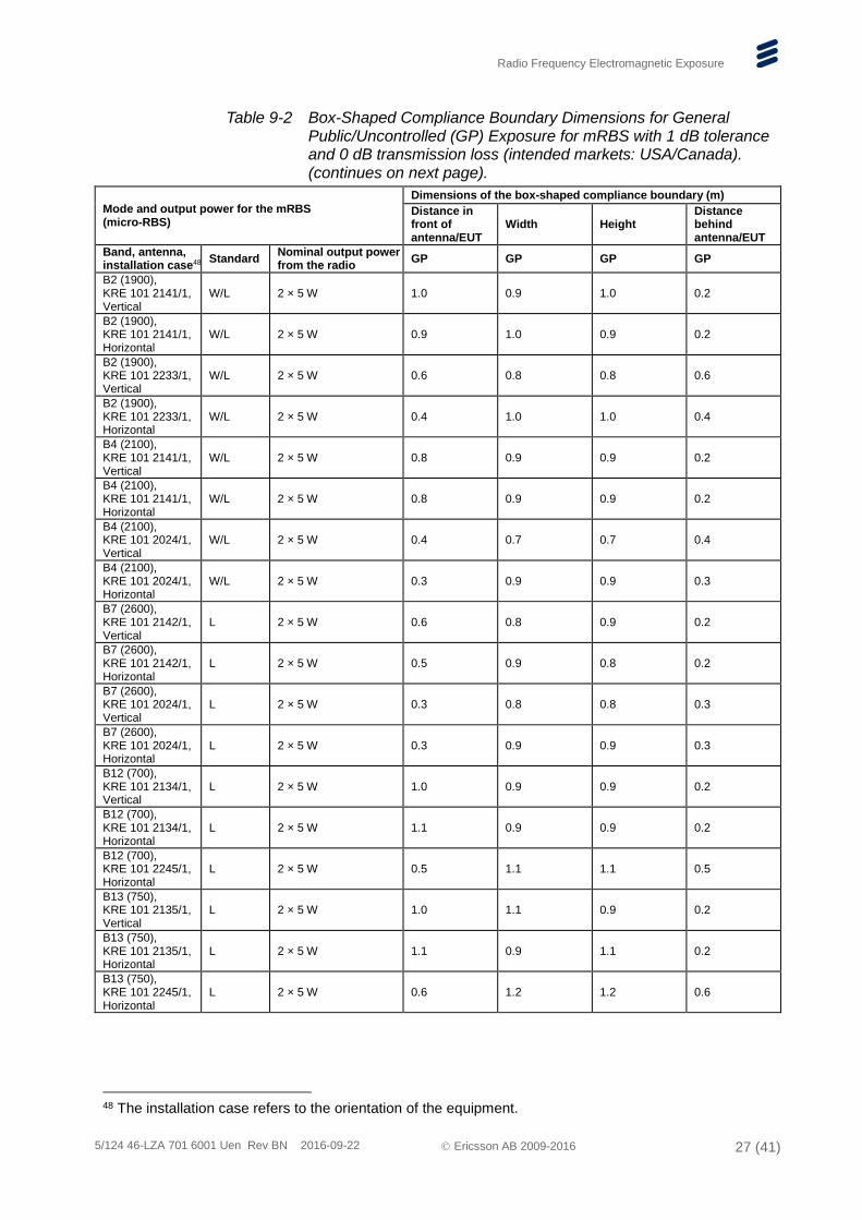
Table 9-2 Box-Shaped Compliance Boundary Dimensions for General Public/Uncontrolled (GP) Exposure for mRBS with 1 dB tolerance and 0 dB transmission loss (intended markets: USA/Canada). (continues on next page).
Mode and output power for the mRBS (micro-RBS)
Dimensions of the box-shaped compliance boundary (m)
Distance in front of antenna/EUT
Width Height Distance behind antenna/EUT
Band, antenna, installation case48
Standard Nominal output power from the radio
GP GP GP GP
B2 (1900), KRE 101 2141/1, Vertical
W/L 2 × 5 W 1.0 0.9 1.0 0.2
B2 (1900), KRE 101 2141/1, Horizontal
W/L 2 × 5 W 0.9 1.0 0.9 0.2
B2 (1900), KRE 101 2233/1, Vertical
W/L 2 × 5 W 0.6 0.8 0.8 0.6
B2 (1900), KRE 101 2233/1, Horizontal
W/L 2 × 5 W 0.4 1.0 1.0 0.4
B4 (2100), KRE 101 2141/1, Vertical
W/L 2 × 5 W 0.8 0.9 0.9 0.2
B4 (2100), KRE 101 2141/1, Horizontal
W/L 2 × 5 W 0.8 0.9 0.9 0.2
B4 (2100), KRE 101 2024/1, Vertical
W/L 2 × 5 W 0.4 0.7 0.7 0.4
B4 (2100), KRE 101 2024/1, Horizontal
W/L 2 × 5 W 0.3 0.9 0.9 0.3
B7 (2600), KRE 101 2142/1, Vertical
L 2 × 5 W 0.6 0.8 0.9 0.2
B7 (2600), KRE 101 2142/1, Horizontal
L 2 × 5 W 0.5 0.9 0.8 0.2
B7 (2600), KRE 101 2024/1, Vertical
L 2 × 5 W 0.3 0.8 0.8 0.3
B7 (2600), KRE 101 2024/1, Horizontal
L 2 × 5 W 0.3 0.9 0.9 0.3
B12 (700), KRE 101 2134/1, Vertical
L 2 × 5 W 1.0 0.9 0.9 0.2
B12 (700), KRE 101 2134/1, Horizontal
L 2 × 5 W 1.1 0.9 0.9 0.2
B12 (700), KRE 101 2245/1, Horizontal
L 2 × 5 W 0.5 1.1 1.1 0.5
B13 (750), KRE 101 2135/1, Vertical
L 2 × 5 W 1.0 1.1 0.9 0.2
B13 (750), KRE 101 2135/1, Horizontal
L 2 × 5 W 1.1 0.9 1.1 0.2
B13 (750), KRE 101 2245/1, Horizontal
L 2 × 5 W 0.6 1.2 1.2 0.6
48 The installation case refers to the orientation of the equipment.
Radio Frequency Electromagnetic Exposure
5/124 46-LZA 701 6001 Uen Rev BN 2016-09-22 Ericsson AB 2009-2016 28 (41)
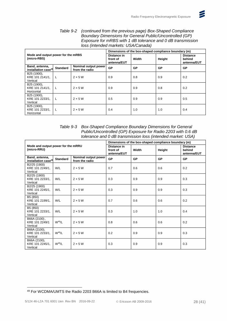
Table 9-2 (continued from the previous page) Box-Shaped Compliance Boundary Dimensions for General Public/Uncontrolled (GP) Exposure for mRBS with 1 dB tolerance and 0 dB transmission loss (intended markets: USA/Canada)
Mode and output power for the mRBS (micro-RBS)
Dimensions of the box-shaped compliance boundary (m)
Distance in front of antenna/EUT
Width Height Distance behind antenna/EUT
Band, antenna, installation case48
Standard Nominal output power from the radio
GP GP GP GP
B25 (1900), KRE 101 2141/1, Vertical
L 2 × 5 W 0.9 0.8 0.9 0.2
B25 (1900), KRE 101 2141/1, Horizontal
L 2 × 5 W 0.9 0.9 0.8 0.2
B25 (1900), KRE 101 2233/1, Vertical
L 2 × 5 W 0.5 0.9 0.9 0.5
B25 (1900), KRE 101 2233/1, Horizontal
L 2 × 5 W 0.4 1.0 1.0 0.4
Table 9-3 Box-Shaped Compliance Boundary Dimensions for General Public/Uncontrolled (GP) Exposure for Radio 2203 with 0.6 dB tolerance and 0 dB transmission loss (intended market: USA)
Mode and output power for the mRRU (micro-RRU)
Dimensions of the box-shaped compliance boundary (m)
Distance in front of antenna/EUT
Width Height Distance behind antenna/EUT
Band, antenna, installation case48
Standard Nominal output power from the radio
GP GP GP GP
B2/25 (1900) KRE 101 2249/1, Vertical
W/L 2 × 5 W 0.7 0.6 0.6 0.2
B2/25 (1900) KRE 101 2233/1, Vertical
W/L 2 × 5 W 0.3 0.9 0.9 0.3
B2/25 (1900) KRE 101 2245/1, Vertical
W/L 2 × 5 W 0.3 0.9 0.9 0.3
B5 (850) KRE 101 2199/1, Vertical
W/L 2 × 5 W 0.7 0.6 0.6 0.2
B5 (850) KRE 101 2233/1, Vertical
W/L 2 × 5 W 0.3 1.0 1.0 0.4
B66A (2100) , KRE 101 2249/1 Vertical
W49/L 2 × 5 W 0.8 0.6 0.6 0.2
B66A (2100), KRE 101 2233/1, Vertical
W49/L 2 × 5 W 0.2 0.9 0.9 0.3
B66A (2100), KRE 101 2245/1, Vertical
W49/L 2 × 5 W 0.3 0.9 0.9 0.3
49 For WCDMA/UMTS the Radio 2203 B66A is limited to B4 frequencies.
Radio Frequency Electromagnetic Exposure
5/124 46-LZA 701 6001 Uen Rev BN 2016-09-22 Ericsson AB 2009-2016 29 (41)
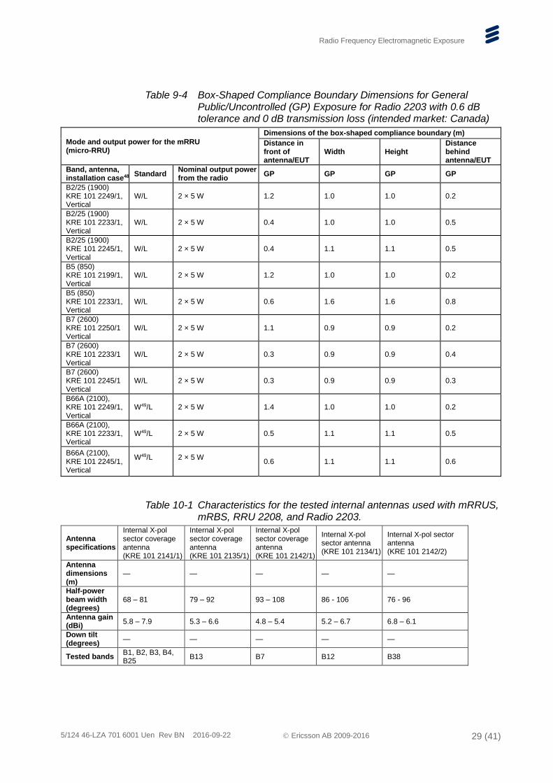
Table 9-4 Box-Shaped Compliance Boundary Dimensions for General Public/Uncontrolled (GP) Exposure for Radio 2203 with 0.6 dB tolerance and 0 dB transmission loss (intended market: Canada)
Mode and output power for the mRRU (micro-RRU)
Dimensions of the box-shaped compliance boundary (m)
Distance in front of antenna/EUT
Width Height Distance behind antenna/EUT
Band, antenna, installation case48
Standard Nominal output power from the radio
GP GP GP GP
B2/25 (1900) KRE 101 2249/1, Vertical
W/L 2 × 5 W 1.2 1.0 1.0 0.2
B2/25 (1900) KRE 101 2233/1, Vertical
W/L 2 × 5 W 0.4 1.0 1.0 0.5
B2/25 (1900) KRE 101 2245/1, Vertical
W/L 2 × 5 W 0.4 1.1 1.1 0.5
B5 (850) KRE 101 2199/1, Vertical
W/L 2 × 5 W 1.2 1.0 1.0 0.2
B5 (850) KRE 101 2233/1, Vertical
W/L 2 × 5 W 0.6 1.6 1.6 0.8
B7 (2600) KRE 101 2250/1 Vertical
W/L 2 × 5 W 1.1 0.9 0.9 0.2
B7 (2600) KRE 101 2233/1 Vertical
W/L 2 × 5 W 0.3 0.9 0.9 0.4
B7 (2600) KRE 101 2245/1 Vertical
W/L 2 × 5 W 0.3 0.9 0.9 0.3
B66A (2100), KRE 101 2249/1, Vertical
W49/L 2 × 5 W 1.4 1.0 1.0 0.2
B66A (2100), KRE 101 2233/1, Vertical
W49/L 2 × 5 W 0.5 1.1 1.1 0.5
B66A (2100), KRE 101 2245/1, Vertical
W49/L
2 × 5 W
0.6 1.1 1.1 0.6
Table 10-1 Characteristics for the tested internal antennas used with mRRUS, mRBS, RRU 2208, and Radio 2203.
Antenna specifications
Internal X-pol sector coverage antenna (KRE 101 2141/1)
Internal X-pol sector coverage antenna (KRE 101 2135/1)
Internal X-pol sector coverage antenna (KRE 101 2142/1)
Internal X-pol sector antenna (KRE 101 2134/1)
Internal X-pol sector antenna (KRE 101 2142/2)
Antenna dimensions (m)
— — — — —
Half-power beam width (degrees)
68 – 81 79 – 92 93 – 108 86 - 106 76 - 96
Antenna gain (dBi)
5.8 – 7.9 5.3 – 6.6 4.8 – 5.4 5.2 – 6.7 6.8 – 6.1
Down tilt (degrees)
— — — — —
Tested bands B1, B2, B3, B4, B25
B13 B7 B12 B38
Radio Frequency Electromagnetic Exposure
5/124 46-LZA 701 6001 Uen Rev BN 2016-09-22 Ericsson AB 2009-2016 30 (41)
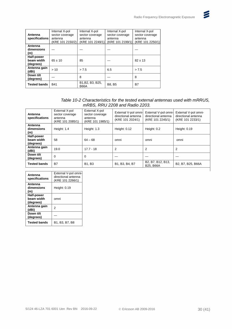
Antenna specifications
Internal X-pol sector coverage antenna (KRE 101 2150/2)
Internal X-pol sector coverage antenna (KRE 101 2249/1)
Internal X-pol sector coverage antenna (KRE 101 2199/1)
Internal X-pol sector coverage antenna (KRE 101 2250/1)
Antenna dimensions (m)
— — — —
Half-power beam width (degrees)
65 ± 10 85 — 82 ± 13
Antenna gain (dBi)
> 10 > 7.5 6.5 > 7.5
Down tilt (degrees)
— 8 — 8
Tested bands B41 B1,B2, B3, B25, B66A
B8, B5 B7
Table 10-2 Characteristics for the tested external antennas used with mRRUS, mRBS, RRU 2208 and Radio 2203.
Antenna specifications
External X-pol sector coverage antenna (KRE 101 2085/1)
External X-pol sector coverage antenna (KRE 101 1985/1)
External V-pol omni-directional antenna (KRE 101 2024/1)
External V-pol omni-directional antenna (KRE 101 2245/1)
External V-pol omni- directional antenna (KRE 101 2233/1)
Antenna dimensions (m)
Height: 1.4 Height: 1.3 Height: 0.12 Height: 0.2 Height: 0.19
Half-power beam width (degrees)
58 64 – 68 omni omni omni
Antenna gain (dBi)
19.0 17.7 - 18 2 2 2
Down tilt (degrees)
0 0 — — —
Tested bands B7 B1, B3 B1, B3, B4, B7 B2, B7, B12, B13, B25, B66A
B2, B7, B25, B66A
Antenna specifications
External V-pol omni-directional antenna (KRE 101 2266/1)
Antenna dimensions (m)
Height: 0.19
Half-power beam width (degrees)
omni
Antenna gain (dBi)
2
Down tilt (degrees)
—
Tested bands B1, B3, B7, B8
Radio Frequency Electromagnetic Exposure
5/124 46-LZA 701 6001 Uen Rev BN 2016-09-22 Ericsson AB 2009-2016 31 (41)
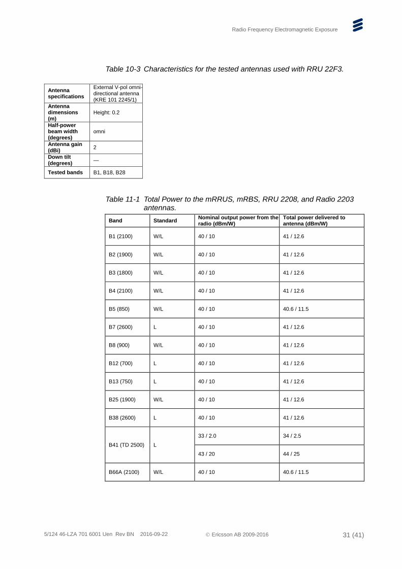
Table 10-3 Characteristics for the tested antennas used with RRU 22F3.
Antenna specifications
External V-pol omni-directional antenna (KRE 101 2245/1)
Antenna dimensions (m)
Height: 0.2
Half-power beam width (degrees)
omni
Antenna gain (dBi)
2
Down tilt (degrees)
—
Tested bands B1, B18, B28
Table 11-1 Total Power to the mRRUS, mRBS, RRU 2208, and Radio 2203 antennas.
Band Standard Nominal output power from the radio (dBm/W)
Total power delivered to antenna (dBm/W)
B1 (2100) W/L 40 / 10 41 / 12.6
B2 (1900) W/L 40 / 10 41 / 12.6
B3 (1800) W/L 40 / 10 41 / 12.6
B4 (2100) W/L 40 / 10 41 / 12.6
B5 (850) W/L 40 / 10 40.6 / 11.5
B7 (2600) L 40 / 10 41 / 12.6
B8 (900) W/L 40 / 10 41 / 12.6
B12 (700) L 40 / 10 41 / 12.6
B13 (750) L 40 / 10 41 / 12.6
B25 (1900) W/L 40 / 10 41 / 12.6
B38 (2600) L 40 / 10 41 / 12.6
B41 (TD 2500) L
33 / 2.0 34 / 2.5
43 / 20 44 / 25
B66A (2100) W/L 40 / 10 40.6 / 11.5
Radio Frequency Electromagnetic Exposure
5/124 46-LZA 701 6001 Uen Rev BN 2016-09-22 Ericsson AB 2009-2016 32 (41)
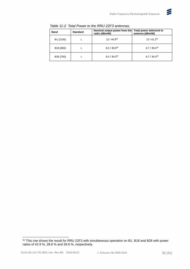
Table 11-2 Total Power to the RRU 22F3 antennas.
Band Standard Nominal output power from the radio (dBm/W)
Total power delivered to antenna (dBm/W)
B1 (2100) L 12 / 40.850 13 / 41.250
B18 (800) L 8.0 / 39.050 8.7 / 39.450
B28 (700) L 8.0 / 39.050 8.7 / 39.450
50 This row shows the result for RRU 22F3 with simultaneous operation on B1, B18 and B28 with power ratios of 42.9 %, 28.6 % and 28.6 %, respectively.
Radio Frequency Electromagnetic Exposure
5/124 46-LZA 701 6001 Uen Rev BN 2016-09-22 Ericsson AB 2009-2016 33 (41)
2.3 Pico RBS
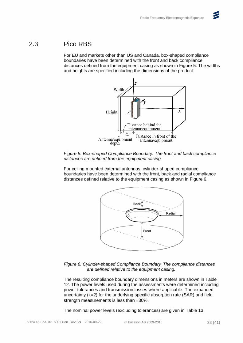
For EU and markets other than US and Canada, box-shaped compliance boundaries have been determined with the front and back compliance distances defined from the equipment casing as shown in Figure 5. The widths and heights are specified including the dimensions of the product.
Figure 5. Box-shaped Compliance Boundary. The front and back compliance distances are defined from the equipment casing.
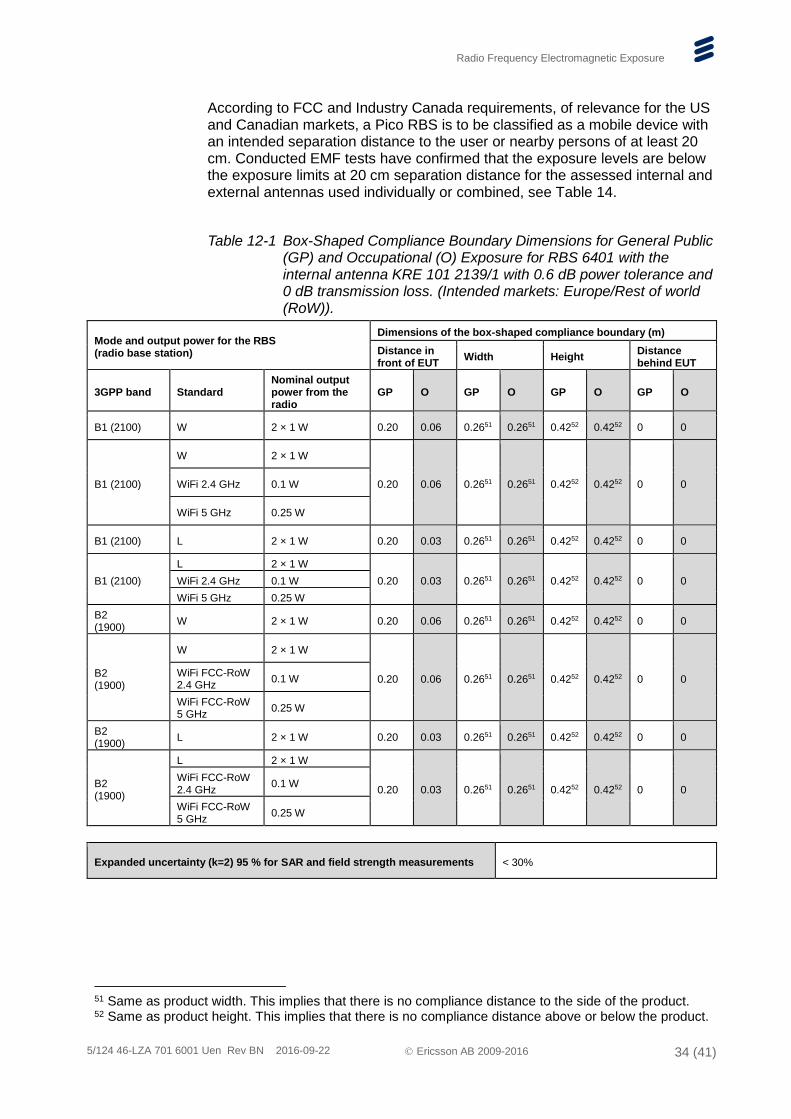
For ceiling mounted external antennas, cylinder-shaped compliance boundaries have been determined with the front, back and radial compliance distances defined relative to the equipment casing as shown in Figure 6.
Figure 6. Cylinder-shaped Compliance Boundary. The compliance distances are defined relative to the equipment casing.
The resulting compliance boundary dimensions in meters are shown in Table 12. The power levels used during the assessments were determined including power tolerances and transmission losses where applicable. The expanded uncertainty (k=2) for the underlying specific absorption rate (SAR) and field
strength measurements is less than 30%.
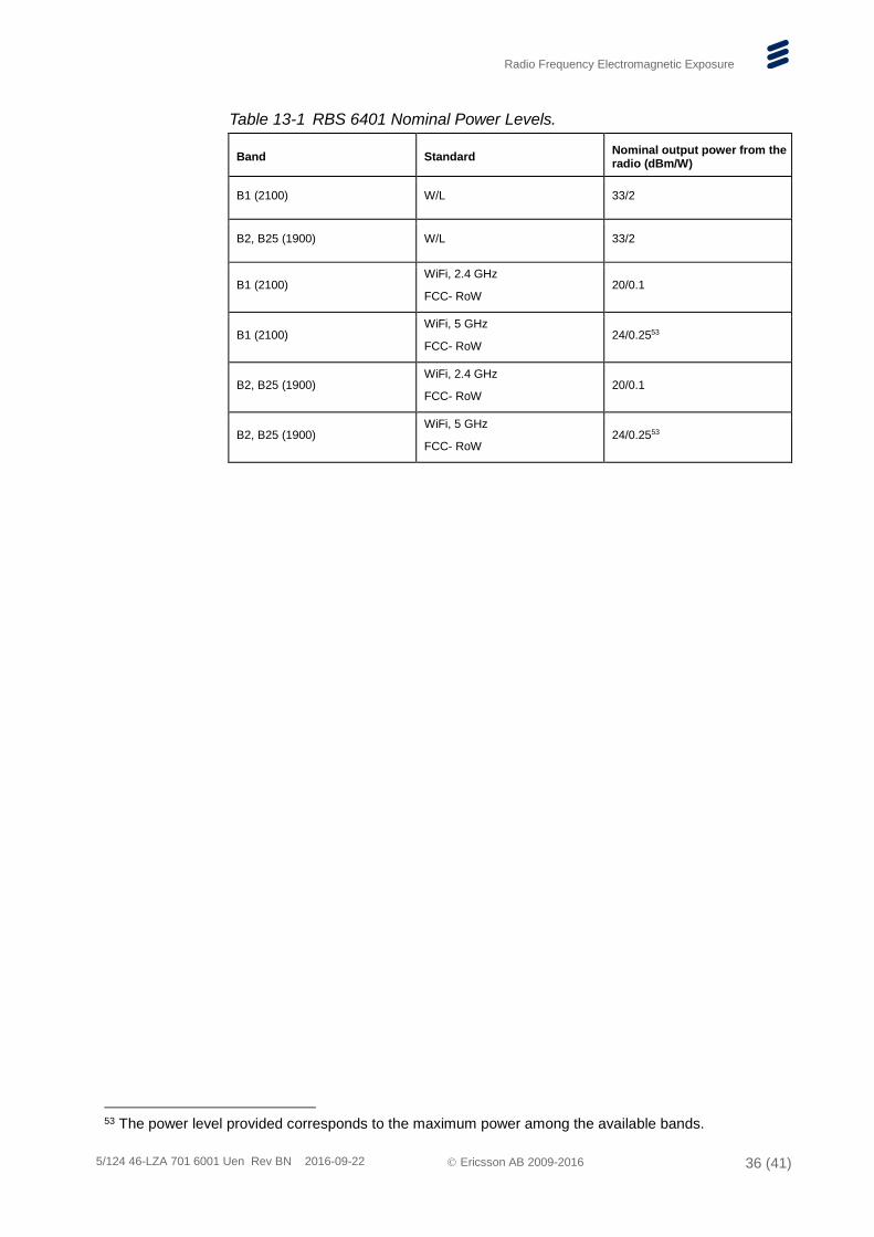
The nominal power levels (excluding tolerances) are given in Table 13.
Radio Frequency Electromagnetic Exposure
5/124 46-LZA 701 6001 Uen Rev BN 2016-09-22 Ericsson AB 2009-2016 34 (41)
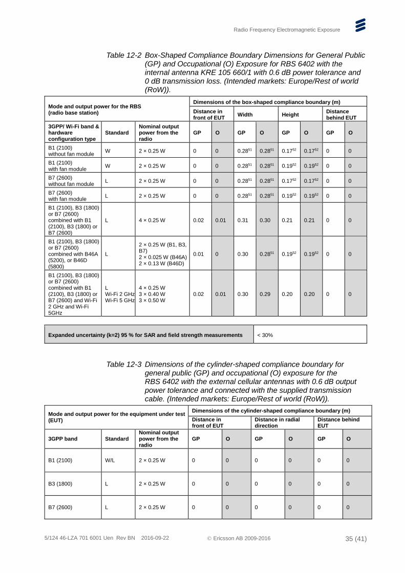
According to FCC and Industry Canada requirements, of relevance for the US and Canadian markets, a Pico RBS is to be classified as a mobile device with an intended separation distance to the user or nearby persons of at least 20 cm. Conducted EMF tests have confirmed that the exposure levels are below the exposure limits at 20 cm separation distance for the assessed internal and external antennas used individually or combined, see Table 14.
Table 12-1 Box-Shaped Compliance Boundary Dimensions for General Public (GP) and Occupational (O) Exposure for RBS 6401 with the internal antenna KRE 101 2139/1 with 0.6 dB power tolerance and 0 dB transmission loss. (Intended markets: Europe/Rest of world (RoW)).
Mode and output power for the RBS (radio base station)
Dimensions of the box-shaped compliance boundary (m)
Distance in front of EUT
Width Height Distance behind EUT
3GPP band Standard Nominal output power from the radio
GP O GP O GP O GP O
B1 (2100) W 2 × 1 W 0.20 0.06 0.2651 0.2651 0.4252 0.4252 0 0
B1 (2100)
W 2 × 1 W
0.20 0.06 0.2651 0.2651 0.4252 0.4252 0 0 WiFi 2.4 GHz 0.1 W
WiFi 5 GHz 0.25 W
B1 (2100) L 2 × 1 W 0.20 0.03 0.2651 0.2651 0.4252 0.4252 0 0
B1 (2100)
L 2 × 1 W
0.20 0.03 0.2651 0.2651 0.4252 0.4252 0 0 WiFi 2.4 GHz 0.1 W
WiFi 5 GHz 0.25 W
B2 (1900)
W 2 × 1 W 0.20 0.06 0.2651 0.2651 0.4252 0.4252 0 0
B2 (1900)
W 2 × 1 W
0.20 0.06 0.2651 0.2651 0.4252 0.4252 0 0 WiFi FCC-RoW 2.4 GHz
0.1 W
WiFi FCC-RoW 5 GHz
0.25 W
B2 (1900)
L 2 × 1 W 0.20 0.03 0.2651 0.2651 0.4252 0.4252 0 0
B2 (1900)
L 2 × 1 W
0.20 0.03 0.2651 0.2651 0.4252 0.4252 0 0 WiFi FCC-RoW 2.4 GHz
0.1 W
WiFi FCC-RoW 5 GHz
0.25 W
Expanded uncertainty (k=2) 95 % for SAR and field strength measurements < 30%
51 Same as product width. This implies that there is no compliance distance to the side of the product. 52 Same as product height. This implies that there is no compliance distance above or below the product.
Radio Frequency Electromagnetic Exposure
5/124 46-LZA 701 6001 Uen Rev BN 2016-09-22 Ericsson AB 2009-2016 35 (41)
Table 12-2 Box-Shaped Compliance Boundary Dimensions for General Public (GP) and Occupational (O) Exposure for RBS 6402 with the internal antenna KRE 105 660/1 with 0.6 dB power tolerance and 0 dB transmission loss. (Intended markets: Europe/Rest of world (RoW)).
Mode and output power for the RBS (radio base station)
Dimensions of the box-shaped compliance boundary (m)
Distance in front of EUT
Width Height Distance behind EUT
3GPP/ Wi-Fi band & hardware configuration type
Standard Nominal output power from the radio
GP O GP O GP O GP O
B1 (2100) without fan module
W 2 × 0.25 W 0 0 0.2851 0.2851 0.1752 0.1752 0 0
B1 (2100) with fan module
W 2 × 0.25 W 0 0 0.2851 0.2851 0.1952 0.1952 0 0
B7 (2600) without fan module
L 2 × 0.25 W 0 0 0.2851 0.2851 0.1752 0.1752 0 0
B7 (2600) with fan module
L 2 × 0.25 W 0 0 0.2851 0.2851 0.1952 0.1952 0 0
B1 (2100), B3 (1800) or B7 (2600) combined with B1 (2100), B3 (1800) or B7 (2600)
L 4 × 0.25 W 0.02 0.01 0.31 0.30 0.21 0.21 0 0
B1 (2100), B3 (1800) or B7 (2600) combined with B46A (5200), or B46D (5800)
L
2 × 0.25 W (B1, B3, B7) 2 × 0.025 W (B46A) 2 × 0.13 W (B46D)
0.01 0 0.30 0.2851 0.1952 0.1952 0 0
B1 (2100), B3 (1800) or B7 (2600) combined with B1 (2100), B3 (1800) or B7 (2600) and Wi-Fi 2 GHz and Wi-Fi 5GHz
L Wi-Fi 2 GHz Wi-Fi 5 GHz
4 × 0.25 W 3 × 0.40 W 3 × 0.50 W
0.02 0.01 0.30 0.29 0.20 0.20 0 0
Expanded uncertainty (k=2) 95 % for SAR and field strength measurements < 30%
Table 12-3 Dimensions of the cylinder-shaped compliance boundary for general public (GP) and occupational (O) exposure for the RBS 6402 with the external cellular antennas with 0.6 dB output power tolerance and connected with the supplied transmission cable. (Intended markets: Europe/Rest of world (RoW)).
Mode and output power for the equipment under test (EUT)
Dimensions of the cylinder-shaped compliance boundary (m)
Distance in front of EUT
Distance in radial direction
Distance behind EUT
3GPP band Standard Nominal output power from the radio
GP O GP O GP O
B1 (2100) W/L 2 × 0.25 W 0 0 0 0 0 0
B3 (1800) L 2 × 0.25 W 0 0 0 0 0 0
B7 (2600) L 2 × 0.25 W 0 0 0 0 0 0
Radio Frequency Electromagnetic Exposure
5/124 46-LZA 701 6001 Uen Rev BN 2016-09-22 Ericsson AB 2009-2016 36 (41)
Table 13-1 RBS 6401 Nominal Power Levels.
Band Standard Nominal output power from the radio (dBm/W)
B1 (2100) W/L 33/2
B2, B25 (1900) W/L 33/2
B1 (2100) WiFi, 2.4 GHz
FCC- RoW 20/0.1
B1 (2100) WiFi, 5 GHz
FCC- RoW 24/0.2553
B2, B25 (1900) WiFi, 2.4 GHz
FCC- RoW 20/0.1
B2, B25 (1900) WiFi, 5 GHz
FCC- RoW 24/0.2553
53 The power level provided corresponds to the maximum power among the available bands.
Radio Frequency Electromagnetic Exposure
5/124 46-LZA 701 6001 Uen Rev BN 2016-09-22 Ericsson AB 2009-2016 37 (41)
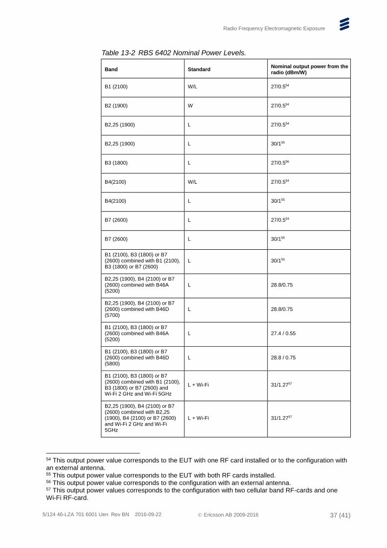
Table 13-2 RBS 6402 Nominal Power Levels.
Band Standard Nominal output power from the radio (dBm/W)
B1 (2100) W/L 27/0.554
B2 (1900) W 27/0.554
B2,25 (1900) L 27/0.554
B2,25 (1900) L 30/155
B3 (1800) L 27/0.556
B4(2100) W/L 27/0.554
B4(2100) L 30/155
B7 (2600) L 27/0.554
B7 (2600) L 30/155
B1 (2100), B3 (1800) or B7 (2600) combined with B1 (2100), B3 (1800) or B7 (2600)
L 30/155
B2,25 (1900), B4 (2100) or B7 (2600) combined with B46A (5200)
L 28.8/0.75
B2,25 (1900), B4 (2100) or B7 (2600) combined with B46D (5700)
L 28.8/0.75
B1 (2100), B3 (1800) or B7 (2600) combined with B46A (5200)
L 27.4 / 0.55
B1 (2100), B3 (1800) or B7 (2600) combined with B46D (5800)
L 28.8 / 0.75
B1 (2100), B3 (1800) or B7 (2600) combined with B1 (2100), B3 (1800) or B7 (2600) and Wi-Fi 2 GHz and Wi-Fi 5GHz
L + Wi-Fi 31/1.2757
B2,25 (1900), B4 (2100) or B7 (2600) combined with B2,25 (1900), B4 (2100) or B7 (2600) and Wi-Fi 2 GHz and Wi-Fi 5GHz
L + Wi-Fi 31/1.2757
54 This output power value corresponds to the EUT with one RF card installed or to the configuration with an external antenna. 55 This output power value corresponds to the EUT with both RF cards installed. 56 This output power value corresponds to the configuration with an external antenna. 57 This output power values corresponds to the configuration with two cellular band RF-cards and one Wi-Fi RF-card.
Radio Frequency Electromagnetic Exposure
5/124 46-LZA 701 6001 Uen Rev BN 2016-09-22 Ericsson AB 2009-2016 38 (41)
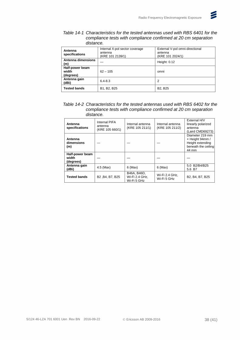
Table 14-1 Characteristics for the tested antennas used with RBS 6401 for the compliance tests with compliance confirmed at 20 cm separation distance.
Antenna specifications
Internal X-pol sector coverage antenna (KRE 101 2139/1)
External V-pol omni-directional antenna (KRE 101 2024/1)
Antenna dimensions (m)
— Height: 0.12
Half-power beam width (degrees)
62 – 105 omni
Antenna gain (dBi)
6.4-8.3 2
Tested bands B1, B2, B25 B2, B25
Table 14-2 Characteristics for the tested antennas used with RBS 6402 for the compliance tests with compliance confirmed at 20 cm separation distance.
Antenna specifications
Internal PIFA antenna (KRE 105 660/1)
Internal antenna (KRE 105 211/1)
Internal antenna (KRE 105 211/2)
External H/V linearly polarized antenna (Laird CMD69273)
Antenna dimensions (m)
— — —
Diameter 219 mm × Height 94mm / Height extending beneath the ceiling 44 mm
Half-power beam width (degrees)
— — — —
Antenna gain (dBi)
4.5 (Max) 6 (Max) 6 (Max) 5.0 B2/B4/B25 5.6 B7
Tested bands B2 ,B4, B7, B25 B46A, B46D, Wi-Fi 2.4 GHz, Wi-Fi 5 GHz
Wi-Fi 2.4 GHz, Wi-Fi 5 GHz
B2, B4, B7, B25
Radio Frequency Electromagnetic Exposure
5/124 46-LZA 701 6001 Uen Rev BN 2016-09-22 Ericsson AB 2009-2016 39 (41)
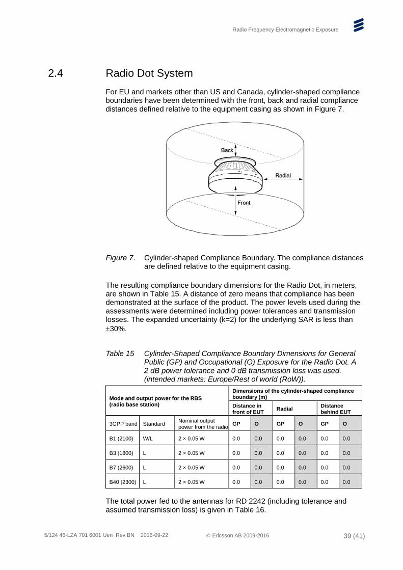
2.4 Radio Dot System
For EU and markets other than US and Canada, cylinder-shaped compliance boundaries have been determined with the front, back and radial compliance distances defined relative to the equipment casing as shown in Figure 7.
The resulting compliance boundary dimensions for the Radio Dot, in meters, are shown in Table 15. A distance of zero means that compliance has been demonstrated at the surface of the product. The power levels used during the assessments were determined including power tolerances and transmission losses. The expanded uncertainty (k=2) for the underlying SAR is less than
30%.
Table 15 Cylinder-Shaped Compliance Boundary Dimensions for General Public (GP) and Occupational (O) Exposure for the Radio Dot. A 2 dB power tolerance and 0 dB transmission loss was used. (intended markets: Europe/Rest of world (RoW)).
Mode and output power for the RBS (radio base station)
Dimensions of the cylinder-shaped compliance boundary (m)
Distance in front of EUT
Radial Distance behind EUT
3GPP band Standard Nominal output power from the radio
GP O GP O GP O
B1 (2100) W/L 2 × 0.05 W 0.0 0.0 0.0 0.0 0.0 0.0
B3 (1800) L 2 × 0.05 W 0.0 0.0 0.0 0.0 0.0 0.0
B7 (2600) L 2 × 0.05 W 0.0 0.0 0.0 0.0 0.0 0.0
B40 (2300) L 2 × 0.05 W 0.0 0.0 0.0 0.0 0.0 0.0
The total power fed to the antennas for RD 2242 (including tolerance and assumed transmission loss) is given in Table 16.
Figure 7. Cylinder-shaped Compliance Boundary. The compliance distances are defined relative to the equipment casing.

Radio Frequency Electromagnetic Exposure
5/124 46-LZA 701 6001 Uen Rev BN 2016-09-22 Ericsson AB 2009-2016 40 (41)
Table 16 RD 2242 Nominal Power Levels.
Band Standard Nominal output power from the radio (dBm/W)
Total power delivered to the antennas (dBm/W)
B1 (2100) W/L 20 / 0.1 22 / 0.16
B2 (1900) W/L 20 / 0.1 22 / 0.16
B3 (1800) L 20 / 0.1 22 / 0.16
B4 (2100) L 20 / 0.1 22 / 0.16
B5 (850) L 20 / 0.1 22 / 0.16
B7 (2600) L 20 / 0.1 22 / 0.16
B13 (700) L 20 / 0.1 22 / 0.16
B17a (700) L 20 / 0.1 22 / 0.16
B40 (2300) L 20 / 0.1 22 / 0.16
According to FCC and Industry Canada requirements, of relevance for the US and Canadian markets, a Radio Dot may be classified as a mobile device with an intended separation distance to the user or nearby persons of at least 20 cm. Conducted EMF tests have confirmed that the RF exposure levels are below the exposure limits at 20 cm separation distance for the assessed internal antenna, see Table 17.
Table 17 Characteristics for the tested antennas used with RD 2242 for the compliance tests with compliance confirmed at 20 cm separation distance.
Antenna specifications Tested bands Maximum antenna gain (dBi)
Internal sector coverage antenna (KRE 101 2191/2)
B2 3
Internal sector coverage antenna (KRE 101 2191/2)
B4 2.5
Internal sector coverage antenna (KRE 101 2187/1)
B5 -0.4
Internal sector coverage antenna (KRE 101 2185/1)
B13 -2.0
Internal sector coverage antenna (KRE 101 2184/2)
B17a -2.6
Radio Frequency Electromagnetic Exposure
5/124 46-LZA 701 6001 Uen Rev BN 2016-09-22 Ericsson AB 2009-2016 41 (41)
References
[1] ICNIRP, “Guidelines for limiting exposure to time-varying electric, magnetic, and electromagnetic fields (up to 300 GHz)”, International Commission on Non-Ionizing Radiation Protection (ICNIRP), Health Physics, vol. 74, pp 494-522, April 1998.
[2] FCC, Code of Federal Regulations CFR title 47, part 1.1310 “Radiofrequency radiation exposure limits”, Federal Communications Commission (FCC), August 1997.
[3] Industry Canada, Radio Standard Specification (RSS) 102, “Radio Frequency Exposure Compliance of Radiocommunication Apparatus (All Frequency Bands)”, 2015.
[4] CENELEC EN 50383, “Basic standard for the calculation and measurement of electromagnetic field strength and SAR related to human exposure from radio base stations and fixed terminal stations for wireless telecommunication systems (110 MHz – 40 GHz)”, European Committee for Electrotechnical Standardization (CENELEC), August 2010.
[5] CENELEC EN 50384, “Product standard to demonstrate the compliance of radio base stations and fixed terminal stations for wireless telecommunication systems with the basic restrictions or the reference levels related to human exposure to radio frequency electromagnetic fields (110 MHz – 40 GHz) – Occupational”, European Committee for Electrotechnical Standardization (CENELEC), August 2002.
[6] CENELEC EN 50385, “Product standard to demonstrate the compliance of radio base stations and fixed terminal stations for wireless telecommunication systems with the basic restrictions or the reference levels related to human exposure to radio frequency electromagnetic fields (110 MHz – 40 GHz) – General public”, European Committee for Electrotechnical Standardization (CENELEC), August 2002.
[7] Ericsson, “Radio Frequency Electromagnetic Fields”, Safety Information, 124 46-EN/LZT 720 0399.