Embed Size (px)
DESCRIPTION
Full Sony LMD 940 user manual
Citation preview

4-134-739-12 (1)
LCD Monitor
© 2009 Sony Corporation
LMD-940W
Operating Instructions Before operating the unit, please read this manual
thoroughly and retain it for future reference.
2
Owner’s Record
The model and serial numbers are located at the rear. Record these numbers in the spaces provided below.Refer to these numbers whenever you call upon your Sony dealer regarding this product.
Model No.____________________Serial No.____________________
• Read these instructions.• Keep these instructions.• Heed all warnings.• Follow all instructions.• Do not use this apparatus near water.• Clean only with dry cloth.• Do not block any ventilation openings.
Install in accordance with the manufacturer's instructions.
• Do not install near any heat sources such as radiators, heat registers, stoves, or other apparatus (including amplifiers) that produce heat.
• Do not defeat the safety purpose of the polarized or grounding-type plug. A polarized plug has two blades with one wider than the other. A grounding-type plug has two blades and a third grounding prong. The wide blade or the third prong are provided for your safety. If the provided plug does not fit into your outlet, consult an electrician for replacement of the obsolete outlet.
• Protect the power cord from being walked on or pinched particularly at plugs, convenience receptacles, and the point where they exit from the apparatus.
• Only use attachments/accessories specified by the manufacturer.
• Use only with the cart, stand, tripod, bracket, or table specified by the manufacturer, or sold with the apparatus. When a cart is used, use caution when moving the cart/apparatus combination to avoid injury from tip-over.
• Unplug this apparatus during lightning storms or when unused for long periods of time.
• Refer all servicing to qualified service personnel. Servicing is required when the apparatus has been damaged in any way, such as power-supply cord or plug is damaged, liquid has been spilled or objects have fallen into the apparatus, the apparatus has been exposed to rain or moisture, does not operate normally, or has been dropped.
WARNING
To reduce the risk of fire or electric shock, do not expose this apparatus to rain or moisture.
To avoid electrical shock, do not open the cabinet. Refer servicing to qualified personnel only.
WARNINGTHIS APPARATUS MUST BE EARTHED.
WARNINGWhen installing the unit, incorporate a readily accessible disconnect device in the fixed wiring, or connect the power plug to an easily accessible socket-outlet near the unit. If a fault should occur during operation of the unit, operate the disconnect device to switch the power supply off, or disconnect the power plug.
Attention-when the product is installed in Rack:
1. Prevention against overloading of branch circuit
When this product is installed in a rack and is supplied power from an outlet on the rack, please make sure that the rack does not overload the supply circuit.
2. Providing protective earthWhen this product is installed in a rack and is supplied power from an outlet on the rack, please confirm that the outlet is provided with a suitable protective earth connection.
Important Safety Instructions
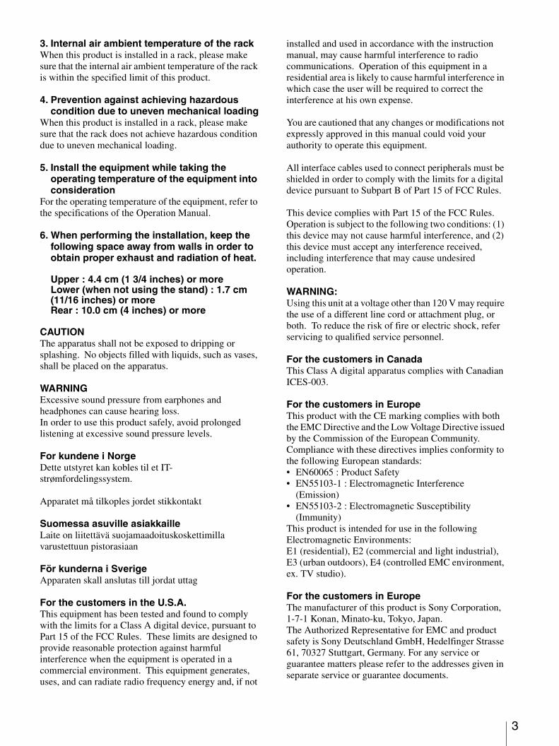
This symbol is intended to alert the user to the presence of uninsulated “dangerous voltage” within the product’s enclosure that may be of sufficient magnitude to constitute a risk of electric shock to persons.
This symbol is intended to alert the user to the presence of important operating and maintenance (servicing) instructions in the literature accompanying the appliance.
3
3. Internal air ambient temperature of the rackWhen this product is installed in a rack, please make sure that the internal air ambient temperature of the rack is within the specified limit of this product.
4. Prevention against achieving hazardous condition due to uneven mechanical loading
When this product is installed in a rack, please make sure that the rack does not achieve hazardous condition due to uneven mechanical loading.
5. Install the equipment while taking the operating temperature of the equipment into consideration
For the operating temperature of the equipment, refer to the specifications of the Operation Manual.
6. When performing the installation, keep the following space away from walls in order to obtain proper exhaust and radiation of heat.
Upper : 4.4 cm (1 3/4 inches) or moreLower (when not using the stand) : 1.7 cm (11/16 inches) or moreRear : 10.0 cm (4 inches) or more
CAUTIONThe apparatus shall not be exposed to dripping or splashing. No objects filled with liquids, such as vases, shall be placed on the apparatus.
WARNINGExcessive sound pressure from earphones and headphones can cause hearing loss.In order to use this product safely, avoid prolonged listening at excessive sound pressure levels.
For kundene i NorgeDette utstyret kan kobles til et IT-strømfordelingssystem.
Apparatet må tilkoples jordet stikkontakt
Suomessa asuville asiakkailleLaite on liitettävä suojamaadoituskoskettimilla varustettuun pistorasiaan
För kunderna i SverigeApparaten skall anslutas till jordat uttag
For the customers in the U.S.A.This equipment has been tested and found to comply with the limits for a Class A digital device, pursuant to Part 15 of the FCC Rules. These limits are designed to provide reasonable protection against harmful interference when the equipment is operated in a commercial environment. This equipment generates, uses, and can radiate radio frequency energy and, if not
installed and used in accordance with the instruction manual, may cause harmful interference to radio communications. Operation of this equipment in a residential area is likely to cause harmful interference in which case the user will be required to correct the interference at his own expense.
You are cautioned that any changes or modifications not expressly approved in this manual could void your authority to operate this equipment.
All interface cables used to connect peripherals must be shielded in order to comply with the limits for a digital device pursuant to Subpart B of Part 15 of FCC Rules.
This device complies with Part 15 of the FCC Rules. Operation is subject to the following two conditions: (1) this device may not cause harmful interference, and (2) this device must accept any interference received, including interference that may cause undesired operation.
WARNING:Using this unit at a voltage other than 120 V may require the use of a different line cord or attachment plug, or both. To reduce the risk of fire or electric shock, refer servicing to qualified service personnel.
For the customers in CanadaThis Class A digital apparatus complies with Canadian ICES-003.
For the customers in EuropeThis product with the CE marking complies with both the EMC Directive and the Low Voltage Directive issued by the Commission of the European Community. Compliance with these directives implies conformity to the following European standards:• EN60065 : Product Safety• EN55103-1 : Electromagnetic Interference
(Emission)• EN55103-2 : Electromagnetic Susceptibility
(Immunity)This product is intended for use in the following Electromagnetic Environments:E1 (residential), E2 (commercial and light industrial), E3 (urban outdoors), E4 (controlled EMC environment, ex. TV studio).
For the customers in EuropeThe manufacturer of this product is Sony Corporation, 1-7-1 Konan, Minato-ku, Tokyo, Japan.The Authorized Representative for EMC and product safety is Sony Deutschland GmbH, Hedelfinger Strasse 61, 70327 Stuttgart, Germany. For any service or guarantee matters please refer to the addresses given in separate service or guarantee documents.

4
For the customers in the USALamp in this product contains mercury. Disposal of these materials may be regulated due to environmental considerations. For disposal or recycling information, please contact your local authorities or the Electronic Industries Alliance (www.eiae.org).
Table of Contents 5
Table of Contents
Precaution .............................................................. 6On Safety ............................................................ 6On Installation .................................................... 6Handling the LCD Screen .................................. 6About the Fluorescent Tube ............................... 6On Cleaning ........................................................ 6On Repacking ..................................................... 7On Mounting on a Rack ..................................... 7On Fan Error ....................................................... 7On AC Adaptor Terminal ................................... 7
Features .................................................................. 7Location and Function of Parts and Controls .... 9
Front Panel ......................................................... 9Input Signals and Adjustable/Setting Items ..... 11Rear/Bottom Panel ........................................... 12
Installing to the Rack (Using MB-531) .............. 13Power Supply ....................................................... 14
Attaching the AC Adaptor ................................ 14Connecting the AC Power Cord ....................... 14
Selecting the Default Settings ............................. 15Selecting the Menu Language ............................ 16Using the Menu .................................................... 17Adjustment Using the Menus ............................. 19
Items ................................................................. 19Adjusting and Changing the Settings ............... 19
STATUS menu............................................. 19COLOR TEMP/SPACE menu ..................... 19USER CONTROL menu.............................. 20USER CONFIG menu.................................. 21REMOTE menu ........................................... 25KEY INHIBIT menu.................................... 27
Troubleshooting ................................................... 27Specifications ....................................................... 28Dimensions ........................................................... 30
Precaution 6
Precaution
On Safety
• Operate the unit only with a power source as specified in the “Specifications” section.
• A nameplate indicating operating voltage, etc., is located on the bottom.
• Should any solid object or liquid fall into the cabinet, unplug the unit and have it checked by qualified personnel before operating it any further.
• Do not drop or place heavy objects on the power cord. If the power cord is damaged, turn off the power immediately. It is dangerous to use the unit with a damaged power cord.
• Unplug the unit from the wall outlet if it is not to be used for several days or more.
• Disconnect the power cord from the AC outlet by grasping the plug, not by pulling the cord.
• The socket-outlet shall be installed near the equipment and shall be easily accessible.
• Do not carry the monitor by holding the stand.• Do not carry the monitor by holding the AC adaptor.
On Installation
• Allow adequate air circulation to prevent internal heat build-up.Do not place the unit on surfaces (rugs, blankets, etc.) or near materials (curtains, draperies) that may block the ventilation holes.
• Do not install the unit in a location near heat sources such as radiators or air ducts, or in a place subject to direct sunlight, excessive dust, mechanical vibration or shock.
Handling the LCD Screen
• The LCD panel fitted to this unit is manufactured with high precision technology, giving a functioning pixel ratio of at least 99.99%. Thus a very small proportion of pixels may be “stuck”, either always off (black), always on (red, green, or blue), or flashing. In addition, over a long period of use, because of the physical characteristics of the liquid crystal display, such “stuck” pixels may appear spontaneously. These problems are not a malfunction.
• Do not leave the LCD screen facing the sun as it can damage the LCD screen. Take care when you place the unit by a window.
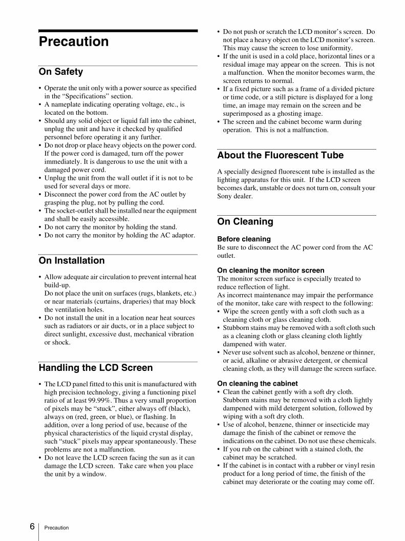
• Do not push or scratch the LCD monitor’s screen. Do not place a heavy object on the LCD monitor’s screen. This may cause the screen to lose uniformity.
• If the unit is used in a cold place, horizontal lines or a residual image may appear on the screen. This is not a malfunction. When the monitor becomes warm, the screen returns to normal.
• If a fixed picture such as a frame of a divided picture or time code, or a still picture is displayed for a long time, an image may remain on the screen and be superimposed as a ghosting image.
• The screen and the cabinet become warm during operation. This is not a malfunction.
About the Fluorescent Tube
A specially designed fluorescent tube is installed as the lighting apparatus for this unit. If the LCD screen becomes dark, unstable or does not turn on, consult your Sony dealer.
On Cleaning
Before cleaningBe sure to disconnect the AC power cord from the AC outlet.
On cleaning the monitor screenThe monitor screen surface is especially treated to reduce reflection of light.As incorrect maintenance may impair the performance of the monitor, take care with respect to the following:• Wipe the screen gently with a soft cloth such as a
cleaning cloth or glass cleaning cloth.• Stubborn stains may be removed with a soft cloth such
as a cleaning cloth or glass cleaning cloth lightly dampened with water.
• Never use solvent such as alcohol, benzene or thinner, or acid, alkaline or abrasive detergent, or chemical cleaning cloth, as they will damage the screen surface.
On cleaning the cabinet• Clean the cabinet gently with a soft dry cloth.
Stubborn stains may be removed with a cloth lightly dampened with mild detergent solution, followed by wiping with a soft dry cloth.
• Use of alcohol, benzene, thinner or insecticide may damage the finish of the cabinet or remove the indications on the cabinet. Do not use these chemicals.
• If you rub on the cabinet with a stained cloth, the cabinet may be scratched.
• If the cabinet is in contact with a rubber or vinyl resin product for a long period of time, the finish of the cabinet may deteriorate or the coating may come off.
Features 7
On Repacking
Do not throw away the carton and packing materials. They make an ideal container which to transport the unit.
On Mounting on a Rack
Leave 1U space empty above and below the monitor to ensure adequate air circulation or install a fan to maintain the monitor’s performance.
If you have any questions about this unit, contact your authorized Sony dealer.
On Fan Error
The fan for cooling the unit is built in. When the fan stops and the 1 (standby) switch indicator on the front panel flashes in green and amber for fan error indication, turn off the power and contact an authorized Sony dealer.
On AC Adaptor Terminal
The AC adaptor terminal of this unit (the connector for AC adaptors) is a consumable part. The unit may not operate properly if the pins of the AC adaptor terminal are bent or deformed by shock or vibrations, or if they become corroded due to prolonged outdoor use.Periodic inspections are recommended to keep the unit working properly and to prolong its usable lifetime. Contact your dealer or a Sony service representative for more information about inspections.
Features
The LMD-940W (9 type) is a multiple format LCD monitor for broadcast or business use featuring a precise image and high performance. It supports both digital or analog main broadcast signal and HDMI 1) input. It is also equipped with functions to adjust for various objects or use.
1) HDMI, the HDMI logo and High-Definition Multimedia Interface are trademarks or registered trademarks of HDMI Licensing LLC.
High brightness LCD panelBecause of precise image, wide viewing angle technology and high speed response, real color image can be reproduced. Use the light intercepting hood, connector protector and carrying handle (optional Sony VF-510 Monitor ENG Kit) for outdoor use.
Multi-formatThe monitor supports video, HDMI, SDI (3G/HD/SD) signals and NTSC/PAL color systems.
For more information, see “Available signal formats” on page 29.
External remote functionThe input signal is selected or various items are adjusted by use of the serial (Ethernet) remote function. Up to 32 monitors and control units (max. 4) can be connected by the Ethernet (10BASE-T/100BASE-TX) connection and controlled remotely on the network. You can control individual monitors or monitor groups simply by entering the monitor ID or group ID number. You can also execute the same operation on all connected monitors, or put all connected monitors into the same setup and adjustment state.
For more information, see SERIAL REMOTE of REMOTE menu on page 25.
Refer to the Operation Manual of the BKM-15R Monitor Control Unit.
Rack mount monitorsUsing the optional MB-531 Mounting Bracket, up to two monitors may be mounted on the EIA-standard 19-inch rack. A height of 4U space-saving design allows more equipment to be installed in tight space, such as an outdoor broadcasting van.
Monitor standYou can set the monitor display in 15° by using the stand.
Features 8
Protection plateYou can attach and detach the LCD screen’s protection plate easily with the four screws.
Strong, slim and lightweightThe strong, slim, and lightweight design of the aluminum die-cast chassis makes the monitor suitable for use with rack mounts or as a portable monitor. This reduces the weight burden on an outdoor broadcasting van, and allows for a wider working space.
Two power systemsThis unit can also be operated by DC 12V or its exclusive AC power adaptor. The AC power adaptor can be mounted on the rear of the monitor for easy use.
Input signal waveform and audio level displayThe waveform of the input signal or the audio level (embedded audio only) can be displayed.
For more information, see SUB INPUT SELECT of “WFM/ALM (waveform monitor and audio level meter) DISPLAY SETTING” on page 22.
Camera focusThis function sharpens the edges of the image more than the amount set by the upper limit of the aperture value in the USER CONTROL menu.This is convenient for focusing with the camera.
Auto chroma/phase functionThe chroma and phase of the decoder are automatically adjusted with the auto chroma/phase function.
Blue only modeIn the blue only mode, a monochrome display is obtained with all three of the R/G/B picture elements driven with a blue signal. This mode is convenient for chroma and phase adjustments and monitoring of signal noise.
H/V delay modeThe horizontal and vertical sync signals can be monitored simultaneously.
Select marker/scan displayVarious items for broadcast use can be displayed. The center marker, aspect marker or display size (scan), etc are displayed by selecting according to use.
For more information, see “MARKER SETTING” on page 22 and SCAN of “FUNCTION BUTTON SETTING” on page 23.
Scan setting /native displayWhen video signals are input, you can set the display size to 0% scan (normal), 5% over scan (over) or zoom mode (full screen).A native display function that maps the pixel of the signal to the panel in one-to-one mode is also equipped.
With this, scaling to correct the screen aspect ratio is done to the horizontal direction of SD signals with non-square pixels (number of horizontal pixels of the signal system is 720 or 1440) or 640 × 480 SD signal of HDMI video.
Select color temperature modeYou can select the color temperature from among two settings (9300 K, 6500 K).
Color space functionYou can select one from among three color space settings (SMPTE-C/EBU/ITU-R BT.709).
On-screen menusYou can set the appropriate settings according to the connected system by using the on-screen menus.
Select language displayYou can select from seven display languages, English, French, German, Spanish, Italian, Japanese and Chinese.
Key inhibit functionYou can inhibit a key function to prevent misoperation.
Monaural speakerThe monitor has a monaural speaker to reproduce sound.
Location and Function of Parts and Controls 9
Location and Function of Parts and Controls
Front Panel
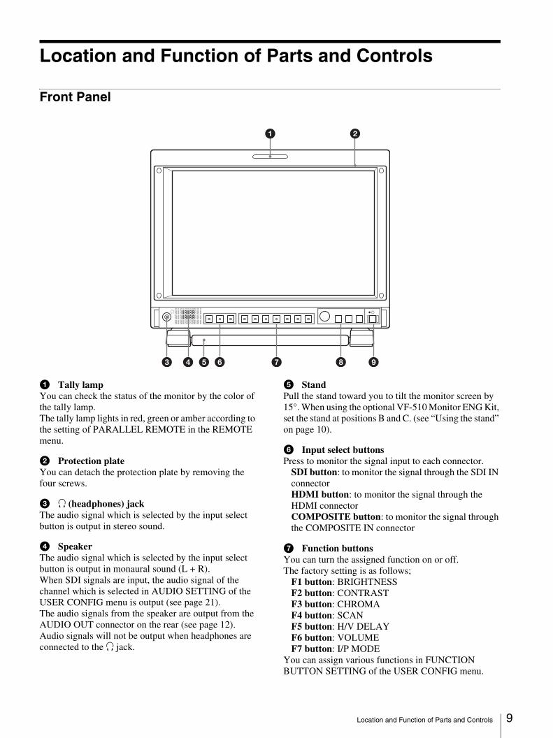
a Tally lampYou can check the status of the monitor by the color of the tally lamp.The tally lamp lights in red, green or amber according to the setting of PARALLEL REMOTE in the REMOTE menu.
b Protection plateYou can detach the protection plate by removing the four screws.
c i (headphones) jackThe audio signal which is selected by the input select button is output in stereo sound.
d SpeakerThe audio signal which is selected by the input select button is output in monaural sound (L + R).When SDI signals are input, the audio signal of the channel which is selected in AUDIO SETTING of the USER CONFIG menu is output (see page 21).The audio signals from the speaker are output from the AUDIO OUT connector on the rear (see page 12).Audio signals will not be output when headphones are connected to the i jack.
e StandPull the stand toward you to tilt the monitor screen by 15°. When using the optional VF-510 Monitor ENG Kit, set the stand at positions B and C. (see “Using the stand” on page 10).
f Input select buttonsPress to monitor the signal input to each connector.
SDI button: to monitor the signal through the SDI IN connectorHDMI button: to monitor the signal through the HDMI connectorCOMPOSITE button: to monitor the signal through the COMPOSITE IN connector
g Function buttonsYou can turn the assigned function on or off.The factory setting is as follows;
F1 button: BRIGHTNESSF2 button: CONTRASTF3 button: CHROMAF4 button: SCANF5 button: H/V DELAYF6 button: VOLUMEF7 button: I/P MODE
You can assign various functions in FUNCTION BUTTON SETTING of the USER CONFIG menu.
i 1
1 2
4 96 7 853
Location and Function of Parts and Controls 10
Press the button BRIGHTNESS, CONTRAST, CHROMA, or VOLUME function assigned to display the adjustment screen. Press the same button again, and the adjustment screen disappears, but you can adjust the value without the setting value display.
For details of the function assigned to the function button, see page 23.
h Menu operation buttonsDisplays or sets the on-screen menu.
Menu selection controlWhen the menu is displayed, turn the control to select a menu item or setting value, and then press the control to confirm the setting.
To light up the characters that represent the names of the buttonsWhen the menu is not displayed, press the menu selection control. Press it again to turn off the lights.
ENTER buttonPress to confirm a selected item on the menu.When the menu is not displayed, press the button to display the distinguished signal format.RETURN buttonWhen the menu is displayed, press the button to reset the value of an item to the previous value (except some items).When the menu is not displayed, press the button to display the names of the functions selected in FUNCTION BUTTON SETTING of the USER CONFIG menu in the lower left of the screen.MENU buttonPress to display the on-screen menu.Press again to clear the menu.
i 1 (standby) switch and indicatorPress to turn on the power when this unit is in standby mode. The indicator lights in green. Press the switch again to set the monitor in standby mode. The indicator goes out. When fan error occurs, the indicator flashes in green and amber alternately. In power saving mode, it lights in amber.
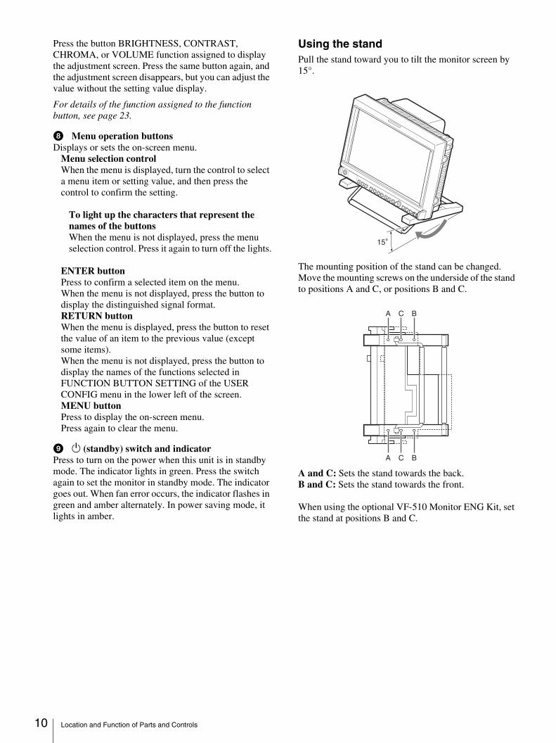
Using the standPull the stand toward you to tilt the monitor screen by 15°.
The mounting position of the stand can be changed.Move the mounting screws on the underside of the stand to positions A and C, or positions B and C.
A and C: Sets the stand towards the back.B and C: Sets the stand towards the front.
When using the optional VF-510 Monitor ENG Kit, set the stand at positions B and C.
A C B
A C B
Location and Function of Parts and Controls 11
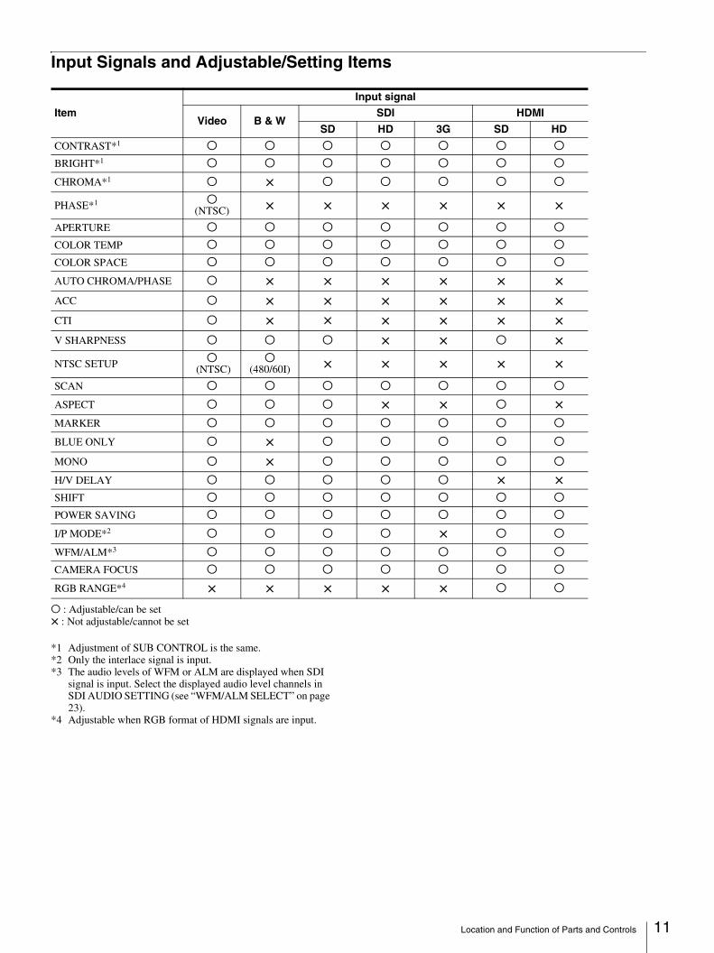
Input Signals and Adjustable/Setting Items
a : Adjustable/can be set× : Not adjustable/cannot be set
*1 Adjustment of SUB CONTROL is the same.*2 Only the interlace signal is input.*3 The audio levels of WFM or ALM are displayed when SDI
signal is input. Select the displayed audio level channels in SDI AUDIO SETTING (see “WFM/ALM SELECT” on page 23).
*4 Adjustable when RGB format of HDMI signals are input.
Input signal
ItemVideo B & W
SDI HDMI
SD HD 3G SD HD
CONTRAST*1 a a a a a a a
BRIGHT*1 a a a a a a a
CHROMA*1 a × a a a a a
PHASE*1 a (NTSC) × × × × × ×
APERTURE a a a a a a a
COLOR TEMP a a a a a a a
COLOR SPACE a a a a a a a
AUTO CHROMA/PHASE a × × × × × ×ACC a × × × × × ×CTI a × × × × × ×V SHARPNESS a a a × × a ×
NTSC SETUP a (NTSC)
a(480/60I) × × × × ×
SCAN a a a a a a a
ASPECT a a a × × a ×MARKER a a a a a a a
BLUE ONLY a × a a a a a
MONO a × a a a a a
H/V DELAY a a a a a × ×SHIFT a a a a a a a
POWER SAVING a a a a a a a
I/P MODE*2 a a a a × a a
WFM/ALM*3 a a a a a a a
CAMERA FOCUS a a a a a a a
RGB RANGE*4 × × × × × a a
Location and Function of Parts and Controls 12
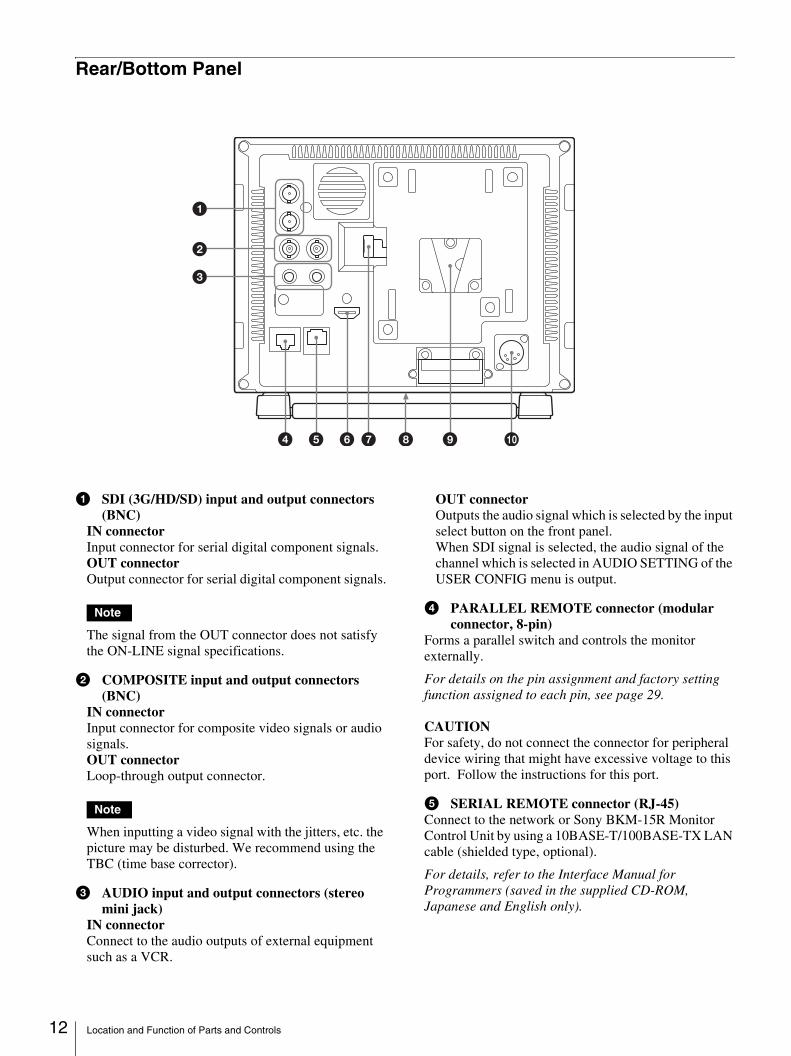
Rear/Bottom Panel
a SDI (3G/HD/SD) input and output connectors (BNC)
IN connectorInput connector for serial digital component signals.OUT connectorOutput connector for serial digital component signals.
Note
The signal from the OUT connector does not satisfy the ON-LINE signal specifications.
b COMPOSITE input and output connectors (BNC)
IN connectorInput connector for composite video signals or audio signals.OUT connectorLoop-through output connector.
Note
When inputting a video signal with the jitters, etc. the picture may be disturbed. We recommend using the TBC (time base corrector).
c AUDIO input and output connectors (stereo mini jack)
IN connectorConnect to the audio outputs of external equipment such as a VCR.
OUT connectorOutputs the audio signal which is selected by the input select button on the front panel.When SDI signal is selected, the audio signal of the channel which is selected in AUDIO SETTING of the USER CONFIG menu is output.
d PARALLEL REMOTE connector (modular connector, 8-pin)
Forms a parallel switch and controls the monitor externally.
For details on the pin assignment and factory setting function assigned to each pin, see page 29.
CAUTIONFor safety, do not connect the connector for peripheral device wiring that might have excessive voltage to this port. Follow the instructions for this port.
e SERIAL REMOTE connector (RJ-45)Connect to the network or Sony BKM-15R Monitor Control Unit by using a 10BASE-T/100BASE-TX LAN cable (shielded type, optional).
For details, refer to the Interface Manual for Programmers (saved in the supplied CD-ROM, Japanese and English only).
4 5 9 06 7 8
1
2
3
Installing to the Rack (Using MB-531) 13
CAUTION• For safety, do not connect the connector for peripheral
device wiring that might have excessive voltage to this port. Follow the instructions for this port.
• When an optional LAN cable is connected, use a shield type cable to prevent miss-operation due to noises.
• The connection speed may be affected by the network system. This unit does not guarantee the communication speed or quality of 10BASE-T/100BASE-TX.
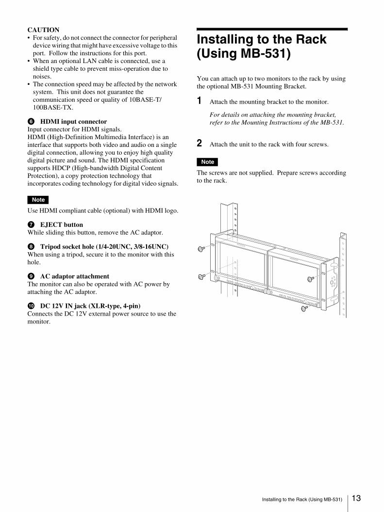
f HDMI input connectorInput connector for HDMI signals.HDMI (High-Definition Multimedia Interface) is an interface that supports both video and audio on a single digital connection, allowing you to enjoy high quality digital picture and sound. The HDMI specification supports HDCP (High-bandwidth Digital Content Protection), a copy protection technology that incorporates coding technology for digital video signals.
Note
Use HDMI compliant cable (optional) with HDMI logo.
g EJECT buttonWhile sliding this button, remove the AC adaptor.
h Tripod socket hole (1/4-20UNC, 3/8-16UNC)When using a tripod, secure it to the monitor with this hole.
i AC adaptor attachmentThe monitor can also be operated with AC power by attaching the AC adaptor.
j DC 12V IN jack (XLR-type, 4-pin)Connects the DC 12V external power source to use the monitor.
Installing to the Rack (Using MB-531)
You can attach up to two monitors to the rack by using the optional MB-531 Mounting Bracket.
1 Attach the mounting bracket to the monitor.
For details on attaching the mounting bracket, refer to the Mounting Instructions of the MB-531.
2 Attach the unit to the rack with four screws.
Note
The screws are not supplied. Prepare screws according to the rack.
Power Supply 14
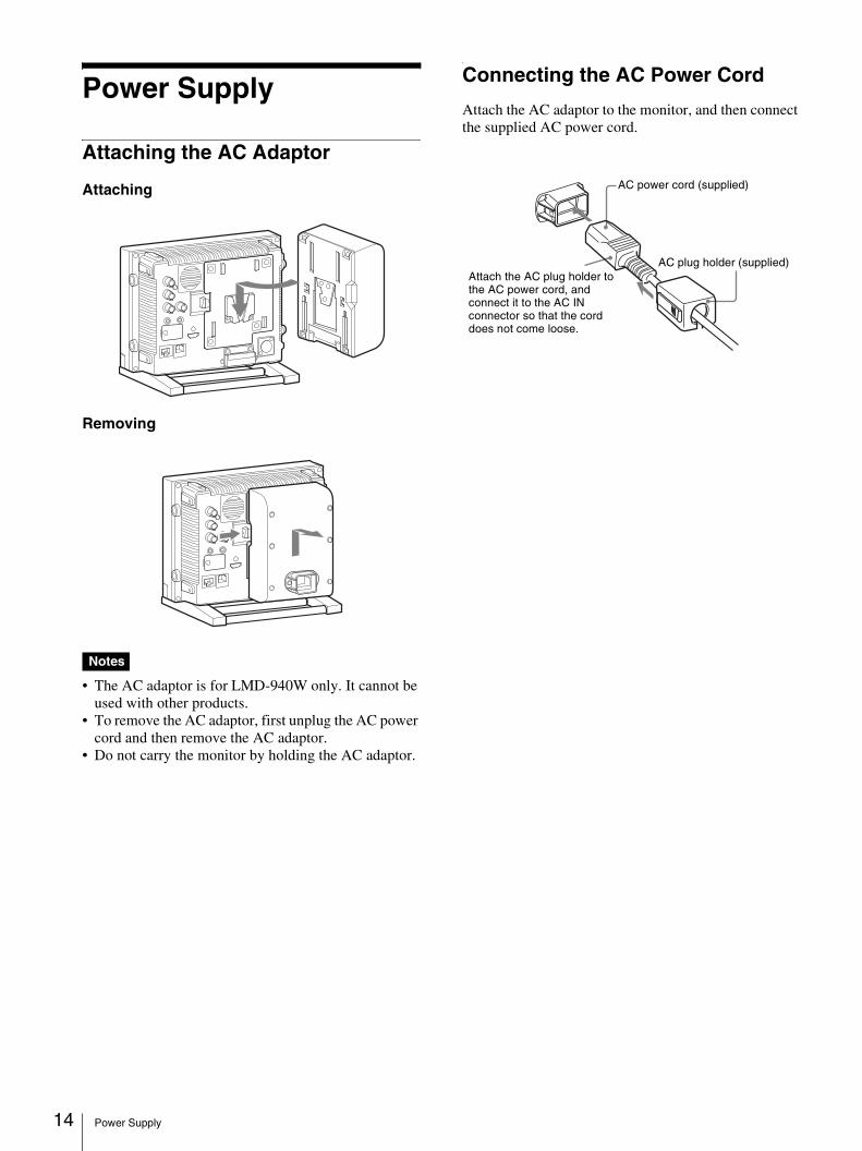
Power Supply
Attaching the AC Adaptor
Attaching
Removing
Notes
• The AC adaptor is for LMD-940W only. It cannot be used with other products.
• To remove the AC adaptor, first unplug the AC power cord and then remove the AC adaptor.
• Do not carry the monitor by holding the AC adaptor.
Connecting the AC Power Cord
Attach the AC adaptor to the monitor, and then connect the supplied AC power cord.
Attach the AC plug holder to the AC power cord, and connect it to the AC IN connector so that the cord does not come loose.
AC power cord (supplied)
AC plug holder (supplied)
Selecting the Default Settings 15
Selecting the Default Settings
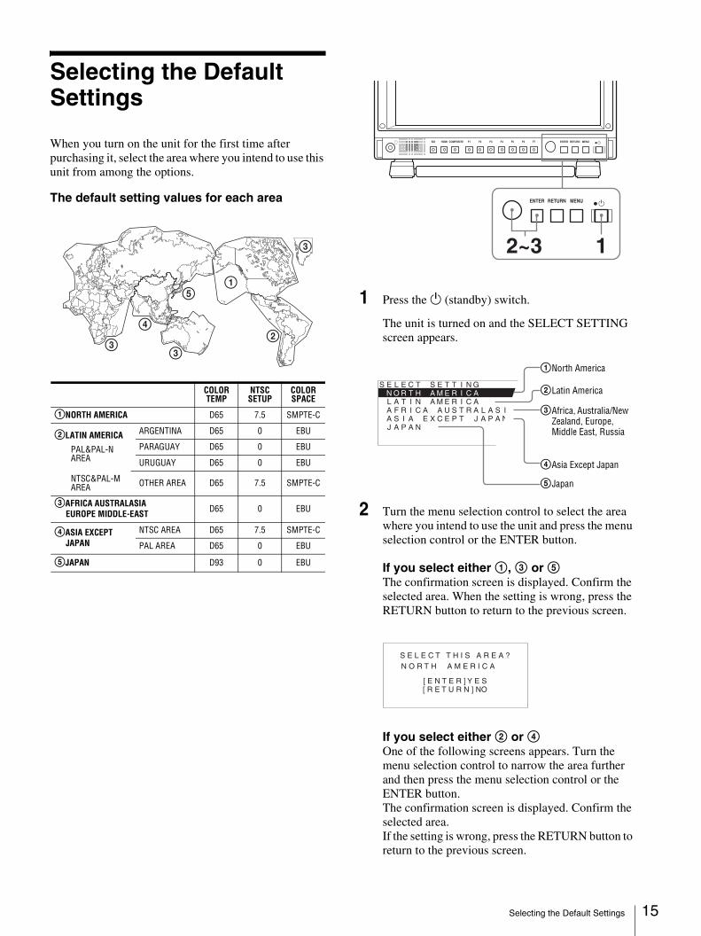
When you turn on the unit for the first time after purchasing it, select the area where you intend to use this unit from among the options.
The default setting values for each area
1 Press the 1 (standby) switch.
The unit is turned on and the SELECT SETTING screen appears.
2 Turn the menu selection control to select the area where you intend to use the unit and press the menu selection control or the ENTER button.
If you select either 1, 3 or 5The confirmation screen is displayed. Confirm the selected area. When the setting is wrong, press the RETURN button to return to the previous screen.
If you select either 2 or 4One of the following screens appears. Turn the menu selection control to narrow the area further and then press the menu selection control or the ENTER button.The confirmation screen is displayed. Confirm the selected area.If the setting is wrong, press the RETURN button to return to the previous screen.
3
3
4
5
3
1
2
COLOR TEMP
NTSC SETUP
COLOR SPACE
1NORTH AMERICA D65 7.5 SMPTE-C
2LATIN AMERICA
PAL&PAL-N AREA
ARGENTINA D65 0 EBU
PARAGUAY D65 0 EBU
URUGUAY D65 0 EBU
NTSC&PAL-M AREA OTHER AREA D65 7.5 SMPTE-C
3AFRICA AUSTRALASIAEUROPE MIDDLE-EAST D65 0 EBU
4ASIA EXCEPT JAPAN
NTSC AREA D65 7.5 SMPTE-C
PAL AREA D65 0 EBU
5JAPAN D93 0 EBU
i COMPOSITEHDMISDI F1 F2 F3 F4 F5 F6 F7 ENTER RETURN MENU 1
ENTER RETURN MENU 1
12~3
S E L E C T S E T T I N G N O R T H _ A M E R I C A L A T I N A M E R I C A A F R I C A A U S T R A L A S I A E A S I A E X C E P T J A P A N J A P A N
1North America
2Latin America
3Africa, Australia/New Zealand, Europe, Middle East, Russia
4Asia Except Japan
5Japan
S E L E C T T H I S A R E A ?
[ E N T E R ] Y E S [ R E T U R N ] NO
N O R T H A M E R I C A
Selecting the Menu Language 16
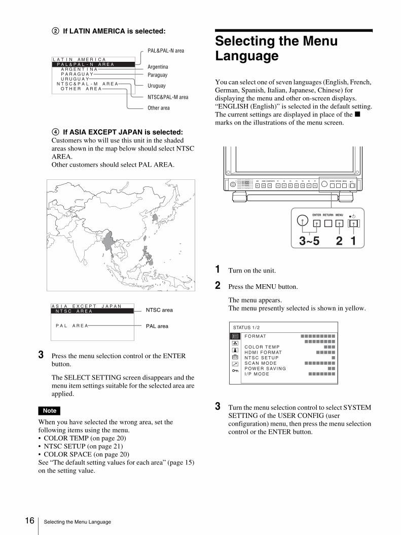
2 If LATIN AMERICA is selected:
4 If ASIA EXCEPT JAPAN is selected:Customers who will use this unit in the shaded areas shown in the map below should select NTSC AREA.Other customers should select PAL AREA.
3 Press the menu selection control or the ENTER button.
The SELECT SETTING screen disappears and the menu item settings suitable for the selected area are applied.
Note
When you have selected the wrong area, set the following items using the menu. • COLOR TEMP (on page 20)• NTSC SETUP (on page 21)• COLOR SPACE (on page 20)See “The default setting values for each area” (page 15) on the setting value.
Selecting the Menu Language
You can select one of seven languages (English, French, German, Spanish, Italian, Japanese, Chinese) for displaying the menu and other on-screen displays.“ENGLISH (English)” is selected in the default setting.The current settings are displayed in place of the x marks on the illustrations of the menu screen.
1 Turn on the unit.
2 Press the MENU button.
The menu appears.The menu presently selected is shown in yellow.
3 Turn the menu selection control to select SYSTEM SETTING of the USER CONFIG (user configuration) menu, then press the menu selection control or the ENTER button.
L A T I N A M E R I C AP A L & P A L - N _ A R E A
A R G E N T I N A P A R A G U A Y U R U G U A Y
N T S C & P A L - M A R E A O T H E R A R E A
PAL&PAL-N area
ArgentinaParaguay
Uruguay
NTSC&PAL-M area
Other area
A S I A E X C E P T J A P A N N T S C _ A R E A P A L A R E A
NTSC area
PAL area
ENTER RETURN MENU 1
i COMPOSITEHDMISDI F1 F2 F3 F4 F5 F6 F7 ENTER RETURN MENU 1
123~5
F O R M AT xxxxxxxxx xxxxxxxxC O L O R T E M P xxxH D M I F O R M AT xxxxxN T S C S E T U P xS C A N M O D E xxxxxxxxP OW E R S AV I N G xxI / P M O D E xxxxxxx
STATUS 1 / 2
Using the Menu 17
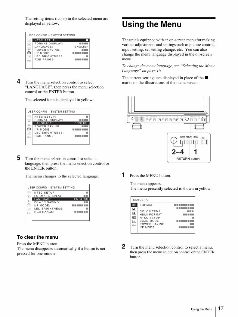
The setting items (icons) in the selected menu are displayed in yellow.
4 Turn the menu selection control to select “LANGUAGE”, then press the menu selection control or the ENTER button.
The selected item is displayed in yellow.
5 Turn the menu selection control to select a language, then press the menu selection control or the ENTER button.
The menu changes to the selected language.
To clear the menuPress the MENU button.The menu disappears automatically if a button is not pressed for one minute.
Using the Menu
The unit is equipped with an on-screen menu for making various adjustments and settings such as picture control, input setting, set setting change, etc. You can also change the menu language displayed in the on-screen menu.
To change the menu language, see “Selecting the Menu Language” on page 16.
The current settings are displayed in place of the x marks on the illustrations of the menu screen.
1 Press the MENU button.
The menu appears.The menu presently selected is shown in yellow.
2 Turn the menu selection control to select a menu, then press the menu selection control or the ENTER button.
N T S C S E T U P : xxxxxx
F O R M AT D I S P L AY: xxxxxx
L A N G UAG E : E N G L I S HP OW E R S AV I N G : xxxxxx
I / P M O D E : xxxxxxx
L E D B R I G H T N E S S : xxxxxx
R G B R A N G E : xxxxxx
USER CONFIG – SYSTEM SETTING
N T S C S E T U P : xxxxxx
F O R M AT D I S P L AY: xxxxxx
L A N G UAG E : E N G L I S HP OW E R S AV I N G : xxxxxx
I / P M O D E : xxxxxxx
L E D B R I G H T N E S S : xxxxxx
R G B R A N G E : xxxxxx
USER CONFIG – SYSTEM SETTING
N T S C S E T U P : xxxxxx
F O R M AT D I S P L AY: xxxxxx
L A N G UAG E : E N G L I S HP OW E R S AV I N G : xxxxxx
I / P M O D E : xxxxxxx
L E D B R I G H T N E S S : xxxxxx
R G B R A N G E : xxxxxx
USER CONFIG – SYSTEM SETTING
ENTER RETURN MENU 1
i COMPOSITEHDMISDI F1 F2 F3 F4 F5 F6 F7 ENTER RETURN MENU 1
12~4RETURN button
F O R M AT xxxxxxxxx xxxxxxxx
C O L O R T E M P xxx H D M I F O R M AT xxxxx
N T S C S E T U P x
S C A N M O D E xxxxxxxx
P OW E R S AV I N G xx
I / P M O D E xxxxxxx
STATUS 1/2
Using the Menu 18
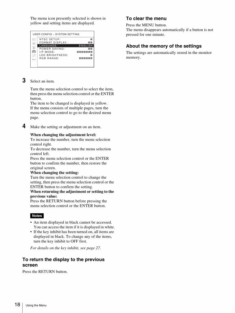
The menu icon presently selected is shown in yellow and setting items are displayed.
3 Select an item.
Turn the menu selection control to select the item, then press the menu selection control or the ENTER button.The item to be changed is displayed in yellow.If the menu consists of multiple pages, turn the menu selection control to go to the desired menu page.
4 Make the setting or adjustment on an item.
When changing the adjustment level:To increase the number, turn the menu selection control right.To decrease the number, turn the menu selection control left.Press the menu selection control or the ENTER button to confirm the number, then restore the original screen.When changing the setting:Turn the menu selection control to change the setting, then press the menu selection control or the ENTER button to confirm the setting.When returning the adjustment or setting to the previous value:Press the RETURN button before pressing the menu selection control or the ENTER button.
Notes
• An item displayed in black cannot be accessed. You can access the item if it is displayed in white.
• If the key inhibit has been turned on, all items are displayed in black. To change any of the items, turn the key inhibit to OFF first.
For details on the key inhibit, see page 27.
To return the display to the previous screenPress the RETURN button.
To clear the menuPress the MENU button.The menu disappears automatically if a button is not pressed for one minute.
About the memory of the settingsThe settings are automatically stored in the monitor memory.
N T S C S E T U P : xxxxxx
F O R M AT D I S P L AY: xxxxxx
L A N G UAG E : E N G L I S HP OW E R S AV I N G : xxxxxx
I / P M O D E : xxxxxxx
L E D B R I G H T N E S S : xxxxxx
R G B R A N G E : xxxxxx
USER CONFIG – SYSTEM SETTING
Adjustment Using the Menus 19
Adjustment Using the Menus
Items
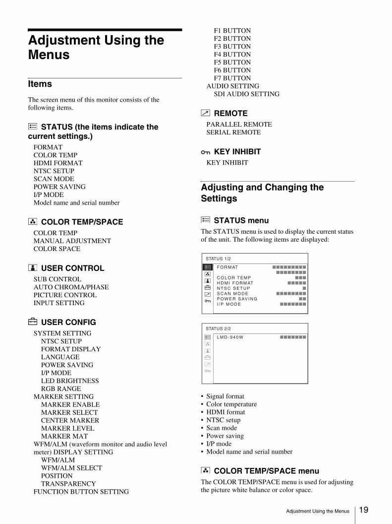
The screen menu of this monitor consists of the following items.
STATUS (the items indicate the current settings.)
FORMATCOLOR TEMPHDMI FORMATNTSC SETUPSCAN MODEPOWER SAVINGI/P MODEModel name and serial number
COLOR TEMP/SPACECOLOR TEMPMANUAL ADJUSTMENTCOLOR SPACE
USER CONTROLSUB CONTROLAUTO CHROMA/PHASEPICTURE CONTROLINPUT SETTING
USER CONFIGSYSTEM SETTING
NTSC SETUPFORMAT DISPLAYLANGUAGEPOWER SAVINGI/P MODELED BRIGHTNESSRGB RANGE
MARKER SETTINGMARKER ENABLEMARKER SELECTCENTER MARKERMARKER LEVELMARKER MAT
WFM/ALM (waveform monitor and audio level meter) DISPLAY SETTING
WFM/ALMWFM/ALM SELECTPOSITIONTRANSPARENCY
FUNCTION BUTTON SETTING
F1 BUTTONF2 BUTTONF3 BUTTONF4 BUTTONF5 BUTTONF6 BUTTONF7 BUTTON
AUDIO SETTINGSDI AUDIO SETTING
REMOTEPARALLEL REMOTESERIAL REMOTE
KEY INHIBITKEY INHIBIT
Adjusting and Changing the Settings
STATUS menuThe STATUS menu is used to display the current status of the unit. The following items are displayed:
• Signal format• Color temperature• HDMI format• NTSC setup• Scan mode• Power saving• I/P mode• Model name and serial number
COLOR TEMP/SPACE menuThe COLOR TEMP/SPACE menu is used for adjusting the picture white balance or color space.
F O R M AT xxxxxxxxx xxxxxxxxC O L O R T E M P xxxH D M I F O R M AT xxxxxN T S C S E T U P xS C A N M O D E xxxxxxxxP OW E R S AV I N G xx I / P M O D E xxxxxxx
STATUS 1/2
L M D - 9 4 0 W xxxxxxx
STATUS 2/2
Adjustment Using the Menus 20
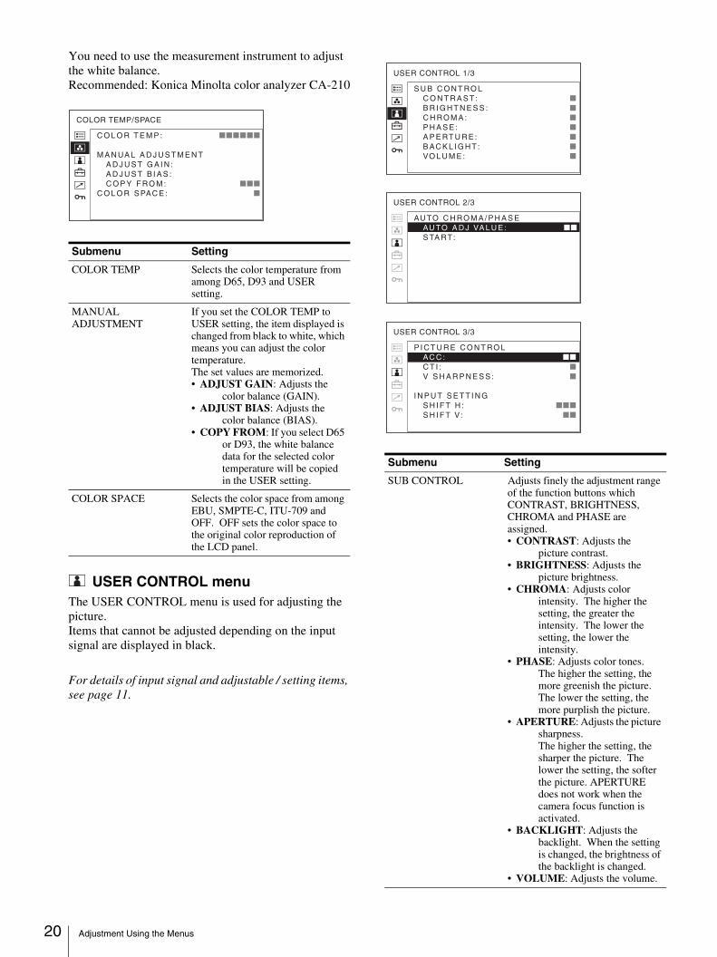
You need to use the measurement instrument to adjust the white balance.Recommended: Konica Minolta color analyzer CA-210
USER CONTROL menuThe USER CONTROL menu is used for adjusting the picture.Items that cannot be adjusted depending on the input signal are displayed in black.
For details of input signal and adjustable / setting items, see page 11.
Submenu Setting
COLOR TEMP Selects the color temperature from among D65, D93 and USER setting.
MANUAL ADJUSTMENT
If you set the COLOR TEMP to USER setting, the item displayed is changed from black to white, which means you can adjust the color temperature.The set values are memorized.• ADJUST GAIN: Adjusts the
color balance (GAIN). • ADJUST BIAS: Adjusts the
color balance (BIAS). • COPY FROM: If you select D65
or D93, the white balance data for the selected color temperature will be copied in the USER setting.
COLOR SPACE Selects the color space from among EBU, SMPTE-C, ITU-709 and OFF. OFF sets the color space to the original color reproduction of the LCD panel.
C O L O R T E M P : xxxxxx
M A N UA L A D J U S T M E N T
A D J U S T G A I N : A D J U S T B I A S : C O P Y F RO M : xxx
C O L O R S PAC E : x
COLOR TEMP/SPACE
Submenu Setting
SUB CONTROL Adjusts finely the adjustment range of the function buttons which CONTRAST, BRIGHTNESS, CHROMA and PHASE are assigned.• CONTRAST: Adjusts the
picture contrast. • BRIGHTNESS: Adjusts the
picture brightness.• CHROMA: Adjusts color
intensity. The higher the setting, the greater the intensity. The lower the setting, the lower the intensity.
• PHASE: Adjusts color tones. The higher the setting, the more greenish the picture. The lower the setting, the more purplish the picture.
• APERTURE: Adjusts the picture sharpness. The higher the setting, the sharper the picture. The lower the setting, the softer the picture. APERTURE does not work when the camera focus function is activated.
• BACKLIGHT: Adjusts the backlight. When the setting is changed, the brightness of the backlight is changed.
• VOLUME: Adjusts the volume.
AU TO C H RO M A / P H A S E AU TO A D J VA L U E : xx
S TA RT:
USER CONTROL 2/3
S U B C O N T RO L C O N T R A S T: x B R I G H T N E S S : x C H RO M A : x P H A S E : x A P E RT U R E : x B AC K L I G H T: x VO L U M E : x
USER CONTROL 1/3
P I C T U R E C O N T RO L AC C : xx C T I : x V S H A R P N E S S : x
I N P U T S E T T I N G S H I F T H : xxx S H I F T V: xx
USER CONTROL 3/3
Adjustment Using the Menus 21
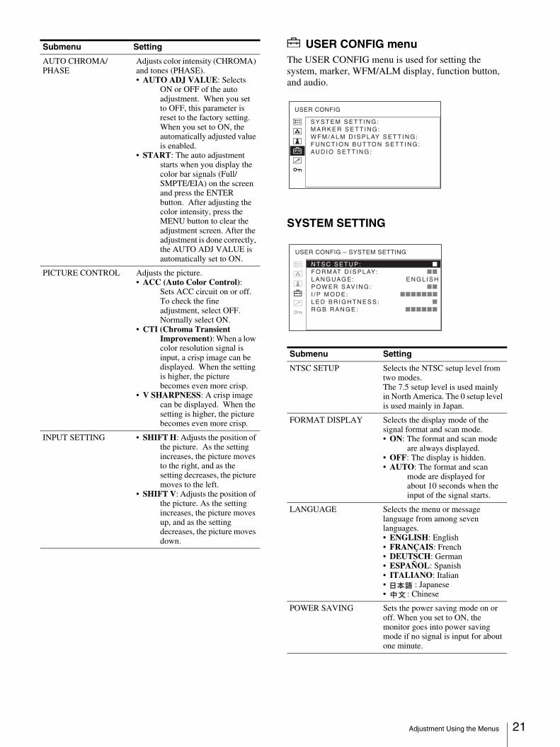
USER CONFIG menuThe USER CONFIG menu is used for setting the system, marker, WFM/ALM display, function button, and audio.
SYSTEM SETTING
AUTO CHROMA/PHASE
Adjusts color intensity (CHROMA) and tones (PHASE). • AUTO ADJ VALUE: Selects
ON or OFF of the auto adjustment. When you set to OFF, this parameter is reset to the factory setting. When you set to ON, the automatically adjusted value is enabled.
• START: The auto adjustment starts when you display the color bar signals (Full/SMPTE/EIA) on the screen and press the ENTER button. After adjusting the color intensity, press the MENU button to clear the adjustment screen. After the adjustment is done correctly, the AUTO ADJ VALUE is automatically set to ON.
PICTURE CONTROL Adjusts the picture.• ACC (Auto Color Control):
Sets ACC circuit on or off.To check the fine adjustment, select OFF. Normally select ON.
• CTI (Chroma Transient Improvement): When a low color resolution signal is input, a crisp image can be displayed. When the setting is higher, the picture becomes even more crisp.
• V SHARPNESS: A crisp image can be displayed. When the setting is higher, the picture becomes even more crisp.
INPUT SETTING • SHIFT H: Adjusts the position of the picture. As the setting increases, the picture moves to the right, and as the setting decreases, the picture moves to the left.
• SHIFT V: Adjusts the position of the picture. As the setting increases, the picture moves up, and as the setting decreases, the picture moves down.
Submenu Setting
Submenu Setting
NTSC SETUP Selects the NTSC setup level from two modes.The 7.5 setup level is used mainly in North America. The 0 setup level is used mainly in Japan.
FORMAT DISPLAY Selects the display mode of the signal format and scan mode.• ON: The format and scan mode
are always displayed.• OFF: The display is hidden.• AUTO: The format and scan
mode are displayed for about 10 seconds when the input of the signal starts.
LANGUAGE Selects the menu or message language from among seven languages. • ENGLISH: English• FRANÇAIS: French• DEUTSCH: German• ESPAÑOL: Spanish• ITALIANO: Italian• : Japanese• : Chinese
POWER SAVING Sets the power saving mode on or off. When you set to ON, the monitor goes into power saving mode if no signal is input for about one minute.
S Y S T E M S E T T I N G : M A R K E R S E T T I N G : W F M / A L M D I S P L AY S E T T I N G : F U N C T I O N B U T TO N S E T T I N G : AU D I O S E T T I N G :
USER CONFIG
N T S C S E T U P : xxxxxxF O R M AT D I S P L AY: xxxxxxL A N G UAG E : E N G L I S HP OW E R S AV I N G : xxxxxxI / P M O D E : xxxxxxxL E D B R I G H T N E S S : xxxxxx R G B R A N G E : xxxxxx
USER CONFIG – SYSTEM SETTING
Adjustment Using the Menus 22
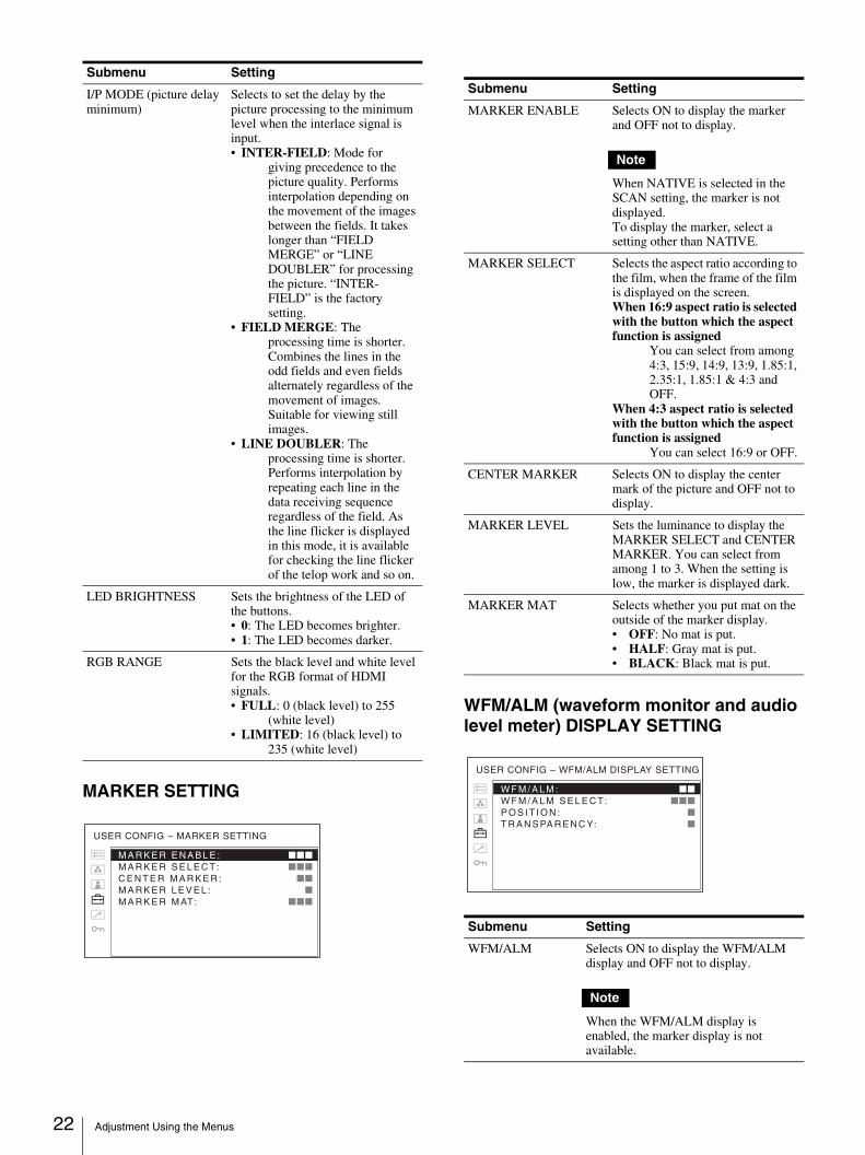
MARKER SETTING
WFM/ALM (waveform monitor and audio level meter) DISPLAY SETTING
I/P MODE (picture delay minimum)
Selects to set the delay by the picture processing to the minimum level when the interlace signal is input.• INTER-FIELD: Mode for
giving precedence to the picture quality. Performs interpolation depending on the movement of the images between the fields. It takes longer than “FIELD MERGE” or “LINE DOUBLER” for processing the picture. “INTER-FIELD” is the factory setting.
• FIELD MERGE: The processing time is shorter. Combines the lines in the odd fields and even fields alternately regardless of the movement of images. Suitable for viewing still images.
• LINE DOUBLER: The processing time is shorter. Performs interpolation by repeating each line in the data receiving sequence regardless of the field. As the line flicker is displayed in this mode, it is available for checking the line flicker of the telop work and so on.
LED BRIGHTNESS Sets the brightness of the LED of the buttons.• 0: The LED becomes brighter.• 1: The LED becomes darker.
RGB RANGE Sets the black level and white level for the RGB format of HDMI signals.• FULL: 0 (black level) to 255
(white level)• LIMITED: 16 (black level) to
235 (white level)
Submenu Setting
M A R K E R E N A B L E : xxxM A R K E R S E L E C T: xxxC E N T E R M A R K E R : xxM A R K E R L E V E L : xM A R K E R M AT: xxx
USER CONFIG – MARKER SETTING
Submenu Setting
MARKER ENABLE Selects ON to display the marker and OFF not to display.
Note
When NATIVE is selected in the SCAN setting, the marker is not displayed.To display the marker, select a setting other than NATIVE.
MARKER SELECT Selects the aspect ratio according to the film, when the frame of the film is displayed on the screen.When 16:9 aspect ratio is selected with the button which the aspect function is assigned
You can select from among 4:3, 15:9, 14:9, 13:9, 1.85:1, 2.35:1, 1.85:1 & 4:3 and OFF.
When 4:3 aspect ratio is selected with the button which the aspect function is assigned
You can select 16:9 or OFF.
CENTER MARKER Selects ON to display the center mark of the picture and OFF not to display.
MARKER LEVEL Sets the luminance to display the MARKER SELECT and CENTER MARKER. You can select from among 1 to 3. When the setting is low, the marker is displayed dark.
MARKER MAT Selects whether you put mat on the outside of the marker display.• OFF: No mat is put.• HALF: Gray mat is put.• BLACK: Black mat is put.
Submenu Setting
WFM/ALM Selects ON to display the WFM/ALM display and OFF not to display.
Note
When the WFM/ALM display is enabled, the marker display is not available.
W F M / A L M : xxW F M / A L M S E L E C T: xxxP O S I T I O N : xT R A N S PA R E N C Y: x
USER CONFIG – WFM/ALM DISPLAY SETTING
Adjustment Using the Menus 23
FUNCTION BUTTON SETTING
About the function assigned to the function button
SCANPress the button to change the scan size of the picture. With every press of the button for the 4:3 display, the picture switches in the sequence NORMAL scan t OVER scan t NATIVE. With every press of the button for the 16:9 display, the picture switches in the sequence NORMAL scan t OVER scan t FULL screen t NATIVE (see “Scan mode image” on page 24).
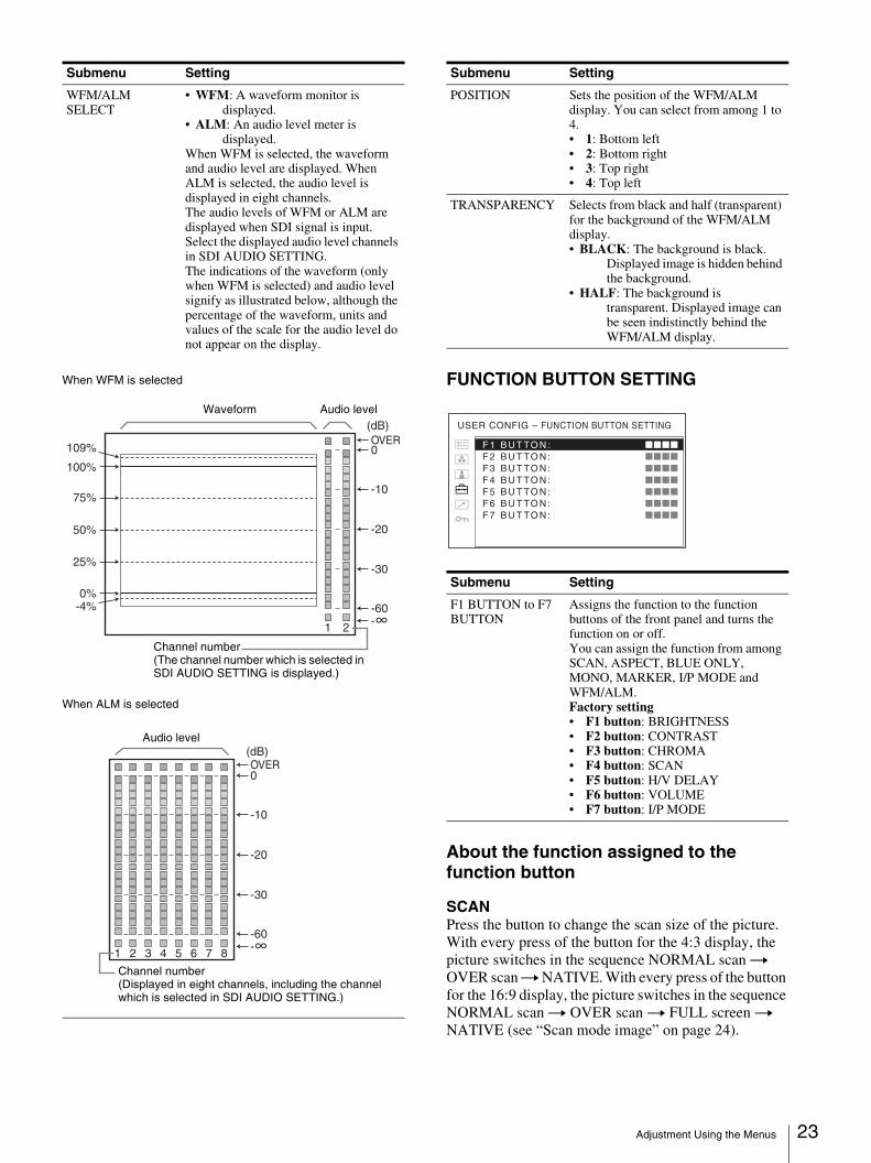
WFM/ALM SELECT
• WFM: A waveform monitor is displayed.
• ALM: An audio level meter is displayed.
When WFM is selected, the waveform and audio level are displayed. When ALM is selected, the audio level is displayed in eight channels.The audio levels of WFM or ALM are displayed when SDI signal is input. Select the displayed audio level channels in SDI AUDIO SETTING.The indications of the waveform (only when WFM is selected) and audio level signify as illustrated below, although the percentage of the waveform, units and values of the scale for the audio level do not appear on the display.
When WFM is selected
When ALM is selected
Submenu Setting
-4%0%
25%
50%
75%
100%
0OVER
(dB)
-10
-20
-30
-60
1 2
109%
Audio levelWaveform
Channel number (The channel number which is selected in SDI AUDIO SETTING is displayed.)
0
(dB)
-10
-20
-30
-60
OVER
1 2 3 4 5 6 7 8
Audio level
Channel number(Displayed in eight channels, including the channel which is selected in SDI AUDIO SETTING.)
POSITION Sets the position of the WFM/ALM display. You can select from among 1 to 4.• 1: Bottom left• 2: Bottom right• 3: Top right• 4: Top left
TRANSPARENCY Selects from black and half (transparent) for the background of the WFM/ALM display.• BLACK: The background is black.
Displayed image is hidden behind the background.
• HALF: The background is transparent. Displayed image can be seen indistinctly behind the WFM/ALM display.
Submenu Setting
F1 BUTTON to F7 BUTTON
Assigns the function to the function buttons of the front panel and turns the function on or off.You can assign the function from among SCAN, ASPECT, BLUE ONLY, MONO, MARKER, I/P MODE and WFM/ALM.Factory setting• F1 button: BRIGHTNESS• F2 button: CONTRAST• F3 button: CHROMA• F4 button: SCAN• F5 button: H/V DELAY• F6 button: VOLUME• F7 button: I/P MODE
Submenu Setting
F 1 B U T TO N : xxxxF 2 B U T TO N : xxxxF 3 B U T TO N : xxxxF 4 B U T TO N : xxxx F 5 B U T TO N : xxxxF 6 B U T TO N : xxxxF 7 B U T TO N : xxxx
USER CONFIG – FUNCTION BUTTON SETTING
Adjustment Using the Menus 24
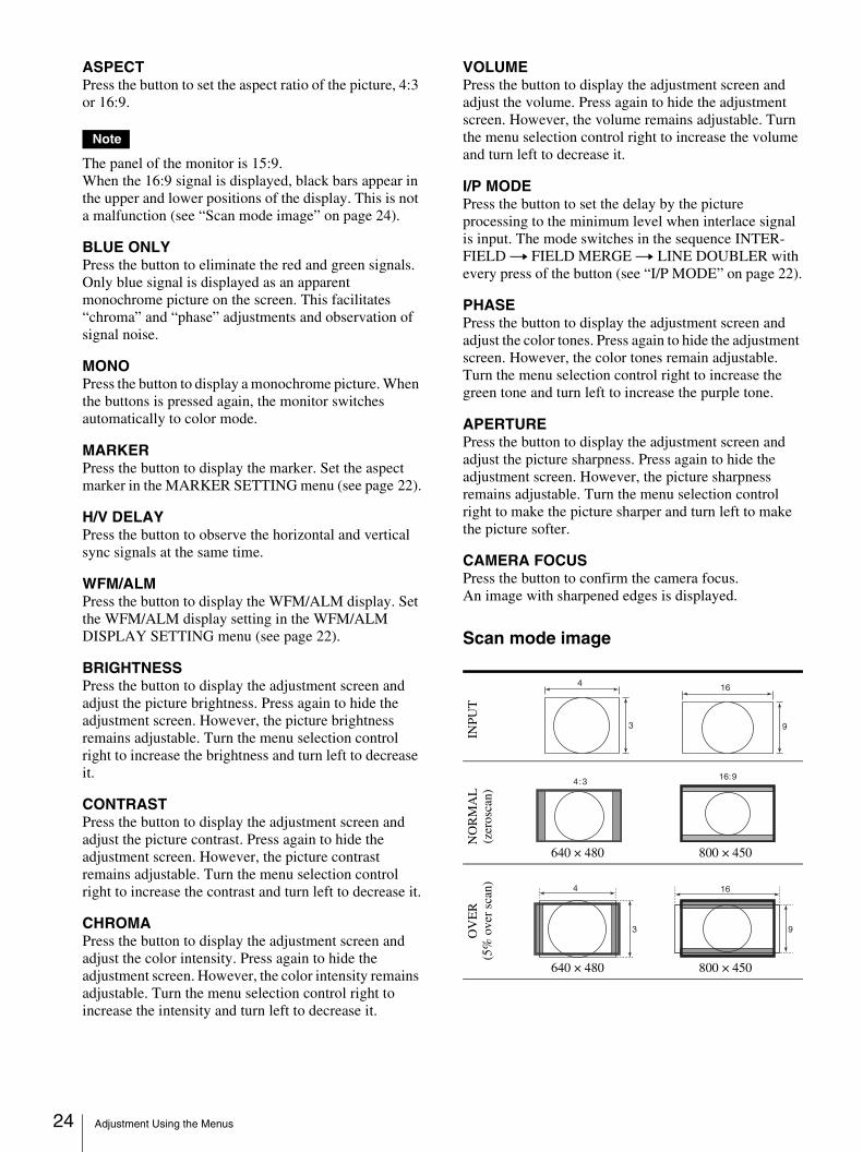
ASPECTPress the button to set the aspect ratio of the picture, 4:3 or 16:9.
Note
The panel of the monitor is 15:9.When the 16:9 signal is displayed, black bars appear in the upper and lower positions of the display. This is not a malfunction (see “Scan mode image” on page 24).
BLUE ONLYPress the button to eliminate the red and green signals. Only blue signal is displayed as an apparent monochrome picture on the screen. This facilitates “chroma” and “phase” adjustments and observation of signal noise.
MONOPress the button to display a monochrome picture. When the buttons is pressed again, the monitor switches automatically to color mode.
MARKERPress the button to display the marker. Set the aspect marker in the MARKER SETTING menu (see page 22).
H/V DELAYPress the button to observe the horizontal and vertical sync signals at the same time.
WFM/ALMPress the button to display the WFM/ALM display. Set the WFM/ALM display setting in the WFM/ALM DISPLAY SETTING menu (see page 22).
BRIGHTNESSPress the button to display the adjustment screen and adjust the picture brightness. Press again to hide the adjustment screen. However, the picture brightness remains adjustable. Turn the menu selection control right to increase the brightness and turn left to decrease it.
CONTRASTPress the button to display the adjustment screen and adjust the picture contrast. Press again to hide the adjustment screen. However, the picture contrast remains adjustable. Turn the menu selection control right to increase the contrast and turn left to decrease it.
CHROMAPress the button to display the adjustment screen and adjust the color intensity. Press again to hide the adjustment screen. However, the color intensity remains adjustable. Turn the menu selection control right to increase the intensity and turn left to decrease it.
VOLUMEPress the button to display the adjustment screen and adjust the volume. Press again to hide the adjustment screen. However, the volume remains adjustable. Turn the menu selection control right to increase the volume and turn left to decrease it.
I/P MODEPress the button to set the delay by the picture processing to the minimum level when interlace signal is input. The mode switches in the sequence INTER-FIELD t FIELD MERGE t LINE DOUBLER with every press of the button (see “I/P MODE” on page 22).
PHASEPress the button to display the adjustment screen and adjust the color tones. Press again to hide the adjustment screen. However, the color tones remain adjustable. Turn the menu selection control right to increase the green tone and turn left to increase the purple tone.
APERTUREPress the button to display the adjustment screen and adjust the picture sharpness. Press again to hide the adjustment screen. However, the picture sharpness remains adjustable. Turn the menu selection control right to make the picture sharper and turn left to make the picture softer.
CAMERA FOCUSPress the button to confirm the camera focus.An image with sharpened edges is displayed.
Scan mode image
640 × 480 800 × 450
640 × 480 800 × 450
INPU
T
4
3
16
9
NO
RM
AL
(zer
osca
n)
4:316:9
OV
ER
(5%
ove
r sc
an)
4
3
16
9
Adjustment Using the Menus 25
AUDIO SETTING
REMOTE menu
–
800 × 480
–
800 × 480
–
800 × 480
768 × 480 (575i, 576P)
–
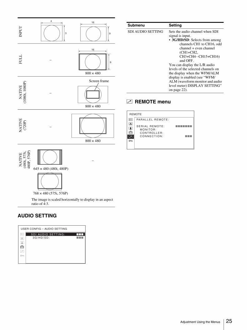
The image is scaled horizontally to display in an aspect ratio of 4:3.
INPU
T4
3
16
9
FU
LL
16
9
NA
TIV
E(1
080i
, 108
0P) Screen frame
NA
TIV
E(7
20P
)N
AT
IVE
(480
i, 57
5i,
480P
, 576
P)
645 × 480 (480i, 480P)
S D I AU D I O S E T T I N G : xxx 3 G / H D / S D : xxx
USER CONFIG – AUDIO SETTING
Submenu Setting
SDI AUDIO SETTING Sets the audio channel when SDI signal is input.• 3G/HD/SD: Selects from among
channels CH1 to CH16, odd channel + even channel (CH1+CH2, CH3+CH4···CH15+CH16) and OFF.
You can display the L/R audio levels of the selected channels on the display when the WFM/ALM display is enabled (see “WFM/ALM (waveform monitor and audio level meter) DISPLAY SETTING” on page 22).
PA R A L L E L R E M OT E :
S E R I A L R E M OT E : xxxxxxx M O N I TO R : C O N T RO L L E R : C O N N E C T I O N : xxx
REMOTE
Adjustment Using the Menus 26
Submenu Setting
PARALLEL REMOTE Selects the PARALLEL REMOTE connector pins for which you want to change the function. You can assign various functions to 1 to 4 pins and 6 to 8 pins. The following lists the functions you can assign to the pins.• – – – (“– – –”: No function is
assigned.)• COMPOSITE• SDI• HDMI• OVERSCAN• FULL• NORMAL• NATIVE• 4:3• 16:9• TALLY R• TALLY G• BLUE ONLY• MONO• H/V DELAY• 16:9 MARKER• 15:9 MARKER• 14:9 MARKER• 13:9 MARKER• 1.85:1 MARKER• 2.35:1 MARKER• 1.85:1 & 4:3 MARKER• 4:3 MARKER• CENTER MARKER• MARKER MAT HALF• MARKER MAT BLACK • WFM/ALM
Notes
• If you use the PARALLEL REMOTE function, you need to connect cables. For more details, see page 29.
• Set MARKER ENABLE (page 22) to ON to control the aspect marker and center marker.
SERIAL REMOTE
MONITOR
CONTROLLER
CONNECTION
Selects the mode to be used.• OFF: SERIAL REMOTE does
not function.• ETHERNET: The monitor is
controlled by the command of Ethernet.
• BKM-15R: Sets BKM-15R.Sets the monitor setting.
MONITOR ID: Sets the ID of the monitor.GROUP ID: Sets the group ID of the monitor.IP ADDRESS: Sets the IP address.SUBNET MASK: Sets the subnet mask. (255.255.255.000)DEFAULT GATEWAY: Sets the default gateway on or off.ADDRESS: Sets the default gateway.CANCEL: Selects to cancel the setting.CONFIRM: Selects to save the setting.
Sets the address of the remote controller.
IP ADDRESS: Sets the IP address.SUBNET MASK: Sets the subnet mask. (255.255.255.000)DEFAULT GATEWAY: Sets the default gateway on or off.ADDRESS: Sets the default gateway.CANCEL: Selects to cancel the setting.CONFIRM: Selects to save the setting.
Sets the connection of the monitor and the controller.
PEER TO PEER: for one to one connectionLAN: for connection via a network
Submenu Setting
Troubleshooting 27
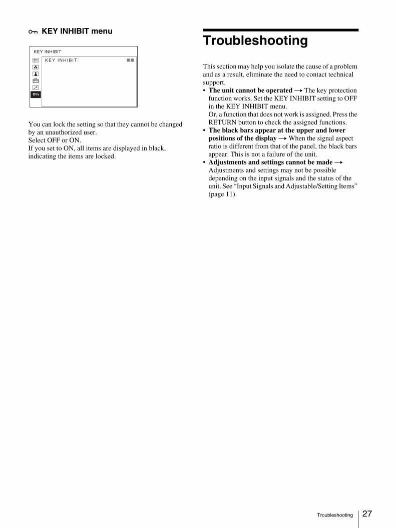
KEY INHIBIT menu
You can lock the setting so that they cannot be changed by an unauthorized user.Select OFF or ON.If you set to ON, all items are displayed in black, indicating the items are locked.
Troubleshooting
This section may help you isolate the cause of a problem and as a result, eliminate the need to contact technical support.• The unit cannot be operated t The key protection
function works. Set the KEY INHIBIT setting to OFF in the KEY INHIBIT menu.Or, a function that does not work is assigned. Press the RETURN button to check the assigned functions.
• The black bars appear at the upper and lower positions of the display t When the signal aspect ratio is different from that of the panel, the black bars appear. This is not a failure of the unit.
• Adjustments and settings cannot be made t Adjustments and settings may not be possible depending on the input signals and the status of the unit. See “Input Signals and Adjustable/Setting Items” (page 11).
K E Y I N H I B I T : xx
KEY INHIBIT
Specifications 28
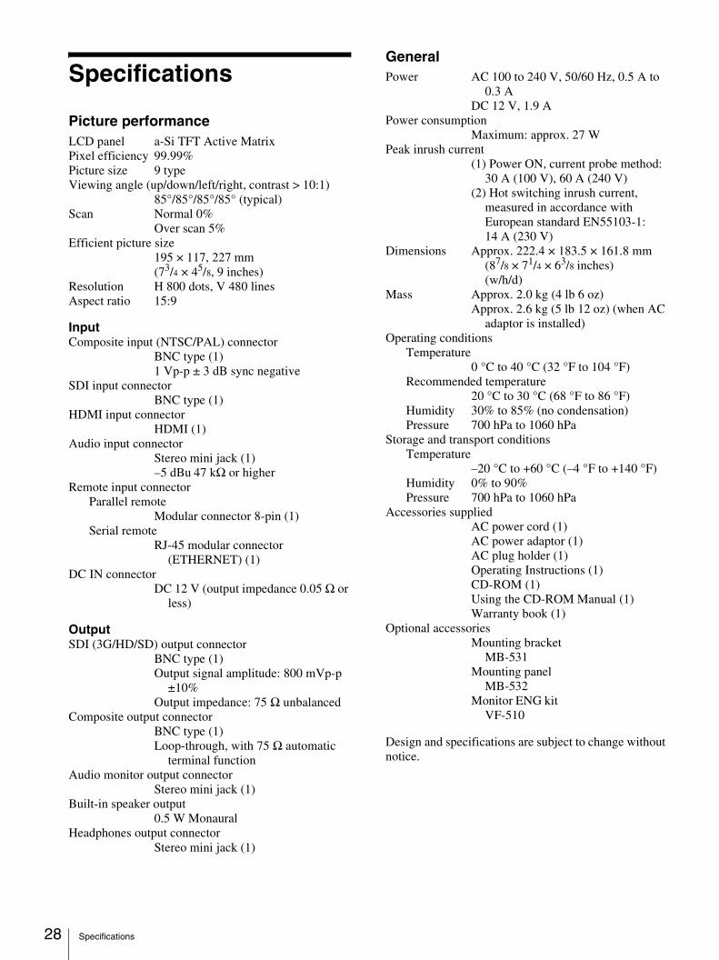
Specifications
Picture performanceLCD panel a-Si TFT Active MatrixPixel efficiency 99.99%Picture size 9 typeViewing angle (up/down/left/right, contrast > 10:1)
85°/85°/85°/85° (typical)Scan Normal 0%
Over scan 5%Efficient picture size
195 × 117, 227 mm(73/4 × 45/8, 9 inches)
Resolution H 800 dots, V 480 linesAspect ratio 15:9
InputComposite input (NTSC/PAL) connector
BNC type (1)1 Vp-p ± 3 dB sync negative
SDI input connectorBNC type (1)
HDMI input connectorHDMI (1)
Audio input connectorStereo mini jack (1)–5 dBu 47 kΩ or higher
Remote input connectorParallel remote
Modular connector 8-pin (1)Serial remote
RJ-45 modular connector (ETHERNET) (1)
DC IN connectorDC 12 V (output impedance 0.05 Ω or
less)
OutputSDI (3G/HD/SD) output connector
BNC type (1)Output signal amplitude: 800 mVp-p
±10%Output impedance: 75 Ω unbalanced
Composite output connectorBNC type (1)Loop-through, with 75 Ω automatic
terminal functionAudio monitor output connector
Stereo mini jack (1)Built-in speaker output
0.5 W MonauralHeadphones output connector
Stereo mini jack (1)
GeneralPower AC 100 to 240 V, 50/60 Hz, 0.5 A to
0.3 ADC 12 V, 1.9 A
Power consumptionMaximum: approx. 27 W
Peak inrush current(1) Power ON, current probe method:
30 A (100 V), 60 A (240 V) (2) Hot switching inrush current,
measured in accordance with European standard EN55103-1: 14 A (230 V)
Dimensions Approx. 222.4 × 183.5 × 161.8 mm (87/8 × 71/4 × 63/8 inches) (w/h/d)
Mass Approx. 2.0 kg (4 lb 6 oz) Approx. 2.6 kg (5 lb 12 oz) (when AC
adaptor is installed)Operating conditions
Temperature0 °C to 40 °C (32 °F to 104 °F)
Recommended temperature20 °C to 30 °C (68 °F to 86 °F)
Humidity 30% to 85% (no condensation)Pressure 700 hPa to 1060 hPa
Storage and transport conditionsTemperature
–20 °C to +60 °C (–4 °F to +140 °F)Humidity 0% to 90%Pressure 700 hPa to 1060 hPa
Accessories suppliedAC power cord (1)AC power adaptor (1)AC plug holder (1)Operating Instructions (1)CD-ROM (1)Using the CD-ROM Manual (1)Warranty book (1)
Optional accessoriesMounting bracket
MB-531Mounting panel
MB-532Monitor ENG kit
VF-510
Design and specifications are subject to change without notice.
Specifications 29
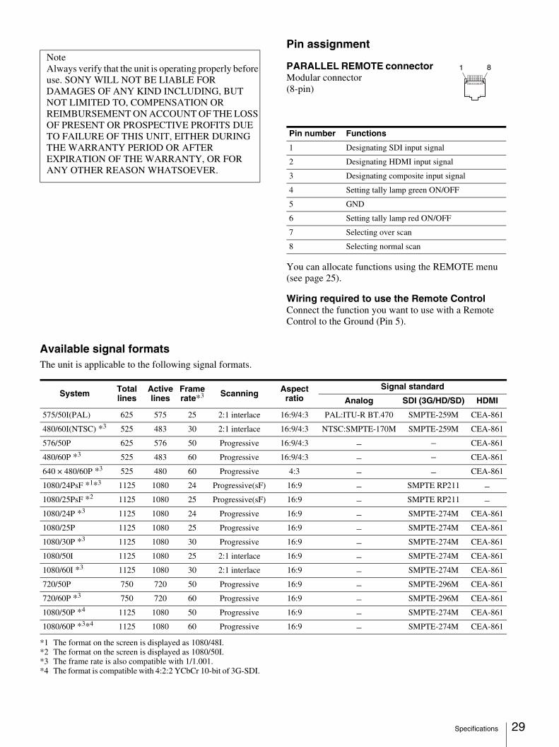
Pin assignment
PARALLEL REMOTE connector Modular connector(8-pin)
You can allocate functions using the REMOTE menu (see page 25).
Wiring required to use the Remote ControlConnect the function you want to use with a Remote Control to the Ground (Pin 5).
Available signal formatsThe unit is applicable to the following signal formats.
*1 The format on the screen is displayed as 1080/48I.*2 The format on the screen is displayed as 1080/50I.*3 The frame rate is also compatible with 1/1.001.*4 The format is compatible with 4:2:2 YCbCr 10-bit of 3G-SDI.
NoteAlways verify that the unit is operating properly before use. SONY WILL NOT BE LIABLE FOR DAMAGES OF ANY KIND INCLUDING, BUT NOT LIMITED TO, COMPENSATION OR REIMBURSEMENT ON ACCOUNT OF THE LOSS OF PRESENT OR PROSPECTIVE PROFITS DUE TO FAILURE OF THIS UNIT, EITHER DURING THE WARRANTY PERIOD OR AFTER EXPIRATION OF THE WARRANTY, OR FOR ANY OTHER REASON WHATSOEVER.
Pin number Functions
1 Designating SDI input signal
2 Designating HDMI input signal
3 Designating composite input signal
4 Setting tally lamp green ON/OFF
5 GND
6 Setting tally lamp red ON/OFF
7 Selecting over scan
8 Selecting normal scan
1 8
System Total lines
Active lines
Frame rate*3 Scanning Aspect
ratioSignal standard
Analog SDI (3G/HD/SD) HDMI
575/50I(PAL) 625 575 25 2:1 interlace 16:9/4:3 PAL:ITU-R BT.470 SMPTE-259M CEA-861
480/60I(NTSC) *3 525 483 30 2:1 interlace 16:9/4:3 NTSC:SMPTE-170M SMPTE-259M CEA-861
576/50P 625 576 50 Progressive 16:9/4:3 – – CEA-861
480/60P *3 525 483 60 Progressive 16:9/4:3 – – CEA-861
640 × 480/60P *3 525 480 60 Progressive 4:3 – – CEA-861
1080/24PsF *1*3 1125 1080 24 Progressive(sF) 16:9 – SMPTE RP211 –1080/25PsF *2 1125 1080 25 Progressive(sF) 16:9 – SMPTE RP211 –1080/24P *3 1125 1080 24 Progressive 16:9 – SMPTE-274M CEA-861
1080/25P 1125 1080 25 Progressive 16:9 – SMPTE-274M CEA-861
1080/30P *3 1125 1080 30 Progressive 16:9 – SMPTE-274M CEA-861
1080/50I 1125 1080 25 2:1 interlace 16:9 – SMPTE-274M CEA-861
1080/60I *3 1125 1080 30 2:1 interlace 16:9 – SMPTE-274M CEA-861
720/50P 750 720 50 Progressive 16:9 – SMPTE-296M CEA-861
720/60P *3 750 720 60 Progressive 16:9 – SMPTE-296M CEA-861
1080/50P *4 1125 1080 50 Progressive 16:9 – SMPTE-274M CEA-861
1080/60P *3*4 1125 1080 60 Progressive 16:9 – SMPTE-274M CEA-861
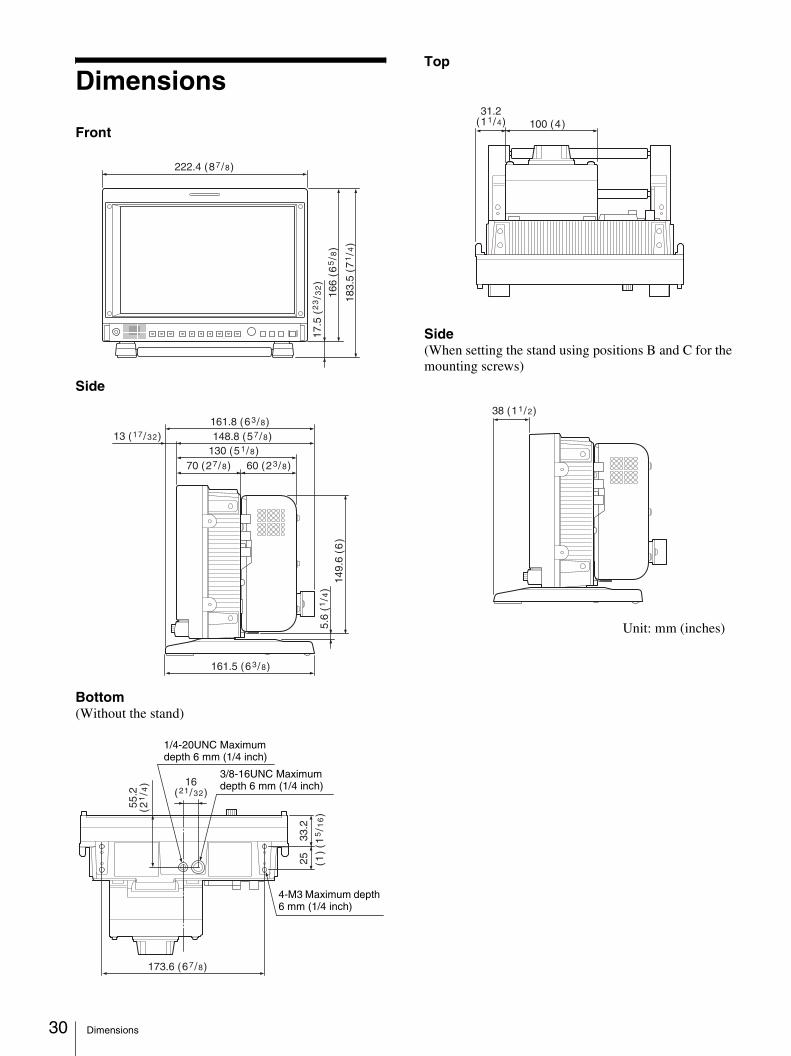
Dimensions 30
Dimensions
Front
Side
Bottom(Without the stand)
Top
Side(When setting the stand using positions B and C for the mounting screws)
222.4 (87/8)
183.
5 (7
1/4
)
166
(65/8
)
17.5
(2
3/3
2)
148.8 (57/8)161.8 (63/8)
13 (17/32)
161.5 (63/8)
130 (51/8)
149.
6 (6
)5.
6 (1
/4)
70 (27/8) 60 (23/8)
173.6 (67/8)
16(21/32)
33.2
(15/1
6)
25 (1)
55.2
(21/4
)
1/4-20UNC Maximum depth 6 mm (1/4 inch)
3/8-16UNC Maximum depth 6 mm (1/4 inch)
4-M3 Maximum depth 6 mm (1/4 inch)
100 (4)31.2
(11/4)
38 (11/2)
Unit: mm (inches)

Sony Corporation