Embed Size (px)
Citation preview
1674IEICE TRANS. COMMUN., VOL.E100–B, NO.9 SEPTEMBER 2017
INVITED PAPER Special Issue on the Past, Present, and Future of Communications Technologies in the IEICE
Radio Access Technologies for Broadband Mobile Communications
Mamoru SAWAHASHI†a), Fellow and Kenichi HIGUCHI††, Member
SUMMARY This paper describes the broadband radio access tech-niques for Universal Mobile Terrestrial Systems (UMTS)/Wideband CodeDivision Multiple Access (W-CDMA), High-Speed Downlink Packet Ac-cess (HSDPA)/High-Speed Uplink Packet Access (HSUPA), Long TermEvolution (LTE), and LTE-Advanced. Major technical pillars are almostidentical regardless of the radio access systems of the respective gener-ations. However, the key techniques that provide distinct performanceimprovements have changed according to the system requirements in eachgeneration. Hence, in this paper, we focus on the key techniques associatedwith the system requirements. We also describe the requirements, radioaccess technology candidates, and challenges toward the future 5G systems.key words: W-CDMA, HSDPA, HSUPA, LTE, LTE-Advanced, multi-accessscheme, radio access technologies
1. Introduction
Commercial service of Japanese analog mobile communi-cations using multi-channel access based on a small cellstructure was initiated in 1979 [1]. A high-capacity urbansystem was launched in 1986 that introduced new techniquesincluding receive diversity, interference detection, and si-multaneous transmission from multiple cell sites [1]. Thedawn of personal wireless communications emerged througha set of user equipment (UE) or compact handset called Mi-croTAC [2]. In 1992, the Personal Digital Cellular (PDC)system was launched, which adopted 3-channel time divi-sion multiple access (TDMA) and π/4-shifted quadraturephase shift keying (QPSK) modulation. In the 1st generationanalog cellular systems and 2nd generation digital cellularsystems, 3-cell frequency reuse was adopted to avoid co-channel interference from neighboring cells. In the 1990s,the number of subscribers increased significantly along withminiaturization and a decrease in power consumption inUEs. One of the most important system requirements for the3rd generation Wideband Code Division Multiple Access(W-CDMA) was to increase the system capacity of voicecommunication channels. Meanwhile, mobile Internet be-came widespread following the spread of Internet access infixed networks. In 2001 when W-CDMA was launched, themain source of traffic changed from voice communications
Manuscript received October 17, 2016.Manuscript revised January 27, 2017.Manuscript publicized March 22, 2017.†The author is with Tokyo City University, Tokyo, 158-8557
Japan.††The author is with Tokyo University of Science, Noda-shi,
278-8510 Japan.a) E-mail: [email protected]
DOI: 10.1587/transcom.2016PFI0015
to data including Internet and video. Hence, high-speedpacket access radio interfaces called High-Speed DownlinkPacket Access (HSDPA) and High-Speed Uplink Packet Ac-cess (HSUPA) were specified to support high-speed datatransmission. HSDPA and HSUPA were enhancements toshared channels carrying user data. Hence, coexistence withW-CDMA was essential because common channels includ-ing control and synchronization channels of the W-CDMAradio interface were used mandatorily. Long Term Evolution(LTE) radio interfaces were specified as the 3rd GenerationPartnership Project (3GPP) Release (Rel.) 8 specifications.LTE achieves higher peak frequency efficiency, cell through-put, and cell-edge user throughput compared to HSDPA andHSUPA based on the Rel. 5 and 6 specifications, respectively.Hence, real mobile broadband services with the peak datarate of greater than 100 Mbps are achieved. LTE-Advancedbased on the Rel. 10 specifications represents enhancementsto LTE and maintains full backward compatibility with LTE.Over the past few decades, and as marked by the specifi-cation of LTE-Advanced, high capacity has become one ofthe most important requirements for cellular systems. Thisrequirement can be satisfied through three approaches: ex-tending the available frequency spectra, densifying base sta-tion (BS) deployment using a small cell, and improving thespectral efficiency by introducing new radio access technolo-gies. Among these approaches, we focus on the radio accesstechnologies in this paper. A multi-access (MA) scheme ormultiplexing scheme for physical channels is very importantand representative of radio access technologies. Figure 1shows enhancements to MA schemes in cellular systemsadopted over the past decades. This paper outlines the MAtechnologies for W-CDMA as the 3rd generation (3G) cel-lular system, LTE and as the 4th generation (4G) cellularsystem, and LTE-Advanced as the 5th generation (5G) cel-lular system. As shown in Fig. 1, W-CDMA achieved anincreased system capacity for voice communication chan-nels using a dedicated channel. HSDPA achieved resourceassignment based on scheduling using a high-speed sharedchannel, while HSUPA used an enhanced dedicated channel.LTE adopts only packet-based access where radio resourcesare assigned based on scheduling. Orthogonal frequencydivision multiples access (OFDMA) and single-carrier fre-quency division multiple access (SC-FDMA) are adopted inthe LTE downlink and uplink, respectively. LTE-Advancedimproves performance levels using carrier aggregation (CA)based on the same MA schemes as those in LTE. Standard-ization of the radio interface of 5G cellular systems has been
Copyright © 2017 The Institute of Electronics, Information and Communication Engineers
SAWAHASHI and HIGUCHI: RADIO ACCESS TECHNOLOGIES FOR BROADBAND MOBILE COMMUNICATIONS1675
Fig. 1 Enhancements to MA schemes in cellular systems.
initiated aiming at completion of the specifications in 2020.This paper describes the broadband radio access tech-
niques for UMTS/W-CDMA, HSDPA/HSUPA, LTE, andLTE-Advanced. The major technical pillars are almost iden-tical regardless of the radio access systems in the respectivegenerations. We also describe the requirements and radioaccess technology candidates toward the future 5G systems.The rest of the paper is organized as follows. Section 2 de-scribes the features of the W-CDMA air interface and keyradio access technologies. Then, Sect. 3 elaborates on thekey radio access technologies for HSDPA and HSUPA. Next,Sect. 4 and Sect. 5 describe the system requirements andkey radio access technologies for LTE and LTE-Advanced,respectively. Section 6 describes the radio interfaces formachine-type communications (MTC) in the 3GPP speci-fications. Section 7 characterizes the system requirements,radio access technology candidates, and challenges to the fu-ture 5G cellular systems aiming at the launch of commercialservice around 2020.
2. W-CDMA
2.1 W-CDMA Radio Interface [3]–[5]
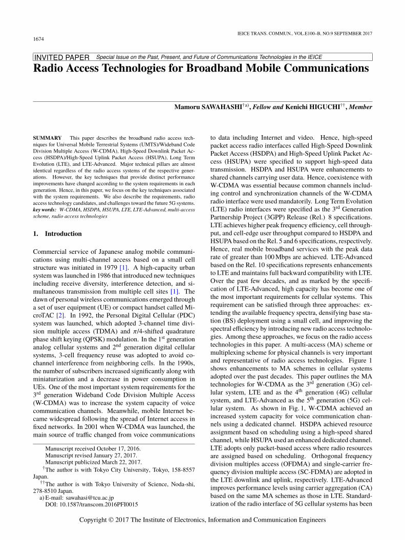
In W-CDMA, one-cell frequency reuse was adopted to in-crease the system capacity of voice communication chan-nels. One-cell frequency reuse was achieved through phys-ical channel multiplexing in the code domain, and the MAinterference from the own and neighboring cells was sup-pressed by the processing gain including the channel cod-ing gain as a part of spreading. Figure 2 shows the radioframe structure for the W-CDMA radio interface. One radioframe length is 10 ms, which comprises 15 slots. A 0.667-ms long slot is the time unit to perform coherent detectionand closed-loop transmit power control (TPC). The chip rateafter spreading is 3.84 Mcps. The transmission bandwidthafter pulse shaping with a root raised-cosine roll-off filter is5 MHz.
User data are carried by a dedicated channel calledthe dedicated physical channel (DPCH). The DPCH com-prises the dedicated physical data channel (DPDCH) anddedicated physical control channel (DPCCH). The DPCCHmultiplexes low-layer control signals including dedicated pi-lot symbols and a TPC bit. The DPDCH multiplexes codeddata symbols. In the downlink, the DPCCH and DPDCH
Fig. 2 Radio frame structure for W-CDMA radio interface.
are multiplexed using time division multiplexing, while theyare multiplexed into in-phase and quadrature components inthe uplink in order to reduce fluctuations in amplitude whenthere are no traffic data. In the downlink, a common pilotchannel (CPICH) is adopted because it achieves lower over-head compared to a user-specific dedicated pilot channel.
We note that different MA schemes with different radioparameters were adopted between frequency division duplex(FDD) and time division duplex (TDD) modes although bothwere based on CDMA. W-CDMA and Time Division (TD)-CDMA were adopted for FDD and TDD, respectively. Thisdecision motivated specification for the same MA schemebetween FDD and TDD in the subsequent LTE radio inter-face. During the standardization processes conducted by theAssociation of Radio Industries and Businesses (ARIB) inJapan and European Telecommunications Standards Insti-tute (ETSI), other MA schemes including TDMA and BandDivision Multiple Access (BDMA) based on OFDM wereproposed. However, in the end, CDMA based MA schemeswere adopted because the system requirement with the high-est priority was to increase the voice communication capac-ity. Although advanced receivers including the multiuser de-tection and successive interference canceller were proposedin academia, the simple coherent Rake receiver became abaseline receiver for CDMA. These results suggest that itis important to satisfy the system requirements and to con-sider the actual implementation cost, which is subject to thedegree of maturity of technologies.
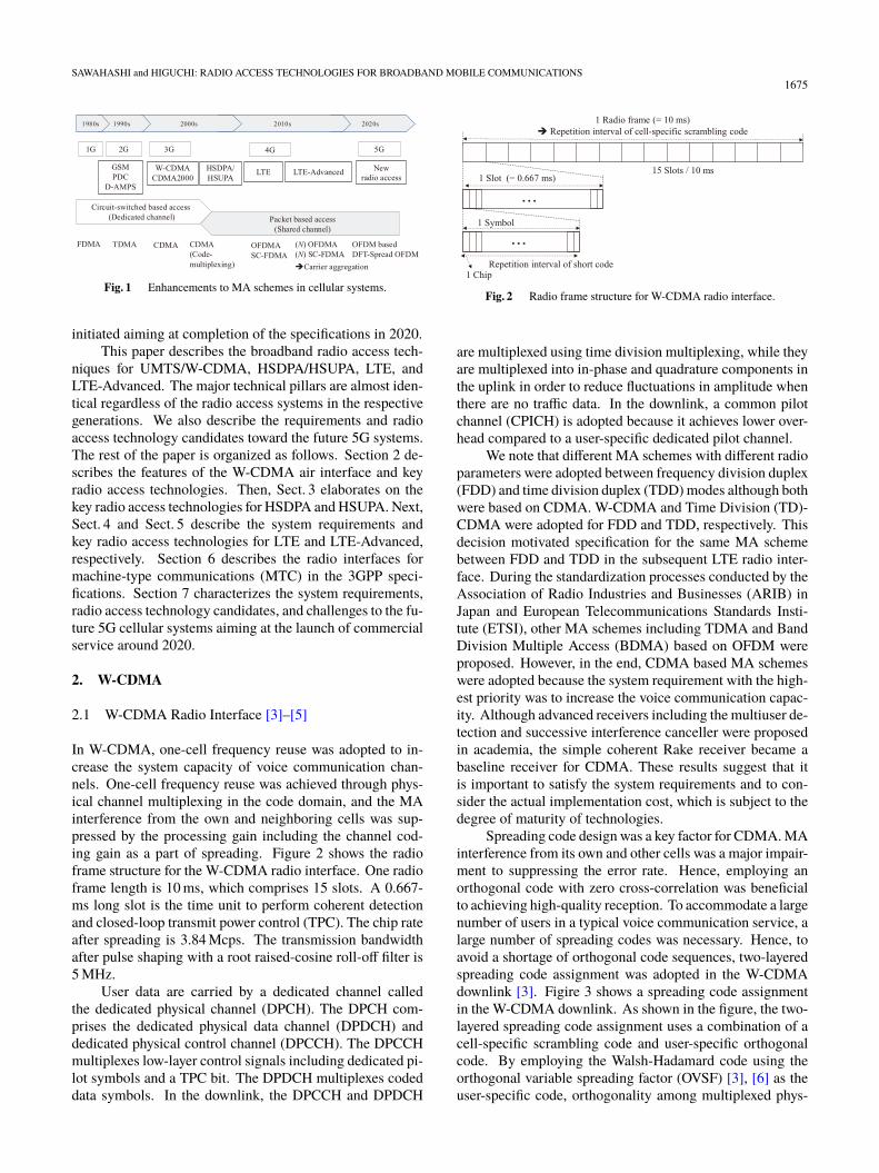
Spreading code design was a key factor for CDMA. MAinterference from its own and other cells was a major impair-ment to suppressing the error rate. Hence, employing anorthogonal code with zero cross-correlation was beneficialto achieving high-quality reception. To accommodate a largenumber of users in a typical voice communication service, alarge number of spreading codes was necessary. Hence, toavoid a shortage of orthogonal code sequences, two-layeredspreading code assignment was adopted in the W-CDMAdownlink [3]. Figire 3 shows a spreading code assignmentin the W-CDMA downlink. As shown in the figure, the two-layered spreading code assignment uses a combination of acell-specific scrambling code and user-specific orthogonalcode. By employing the Walsh-Hadamard code using theorthogonal variable spreading factor (OVSF) [3], [6] as theuser-specific code, orthogonality among multiplexed phys-
1676IEICE TRANS. COMMUN., VOL.E100–B, NO.9 SEPTEMBER 2017
Fig. 3 Two-layered spreading code assignment.
ical channels is achieved within the same propagation pathin a multipath fading channel. Moreover, the cell-specificscrambling code with the length of 10 ms achieves inter-cellinterference randomization. In the uplink, a user-specificscrambling code with one radio frame length is used to facil-itate soft handover. Gold sequences, which are a combinationof two M-sequences, are used for the cell-specific scramblingcode in the downlink and user-specific scrambling code inthe uplink [3].
2.2 Key Radio Access Techniques
Some key radio access technologies were introduced into W-CDMA including signal-to-interference power ratio (SIR)-based TPC, pilot-symbol assisted (PSA) coherent Rake re-ceiver [7], turbo codes [8], and macro diversity or soft han-dover. Fast TPC was adopted in cdmaOne based on InterimStandard (IS) 95, which made CDMA practical in cellularsystems by solving the near-far problem in the uplink [9]. InW-CDMA, the transmit power of a UE was controlled basedon the received signal-to-interference plus noise power ratio(SINR) of each slot (= 0.667 ms). The received SINR wasmeasured by using pilot symbols and the measured receivedSINR value was compared to the target one. The generatedTPC bit was fed back to a transmitter. Figure 4 shows thestructure of the coherent Rake receiver. In W-CDMA, thechip duration, which is the inverse of the chip rate, is 0.23 µs.The delayed multi-paths exceeding the chip duration are re-solved. Because each path suffers from independent fadingvariation, diversity gain is obtained by coherently combin-ing the resolved paths. As shown in Fig. 4, the channelgain of each resolved path is estimated using pilot sym-bols. The complex conjugate of the estimated channel gainis multiplied to the despread signal and combined coherentlywith maximal ratio combining (MRC). The coherent Rakereceiver provides a large diversity gain particularly in an en-vironment with many paths. Two-branch receive diversity isused associated with the Rake receiver. A turbo code wasadopted as the channel code.
These technologies achieved higher system capacitiescompared to the 2G cellular systems using TDMA.
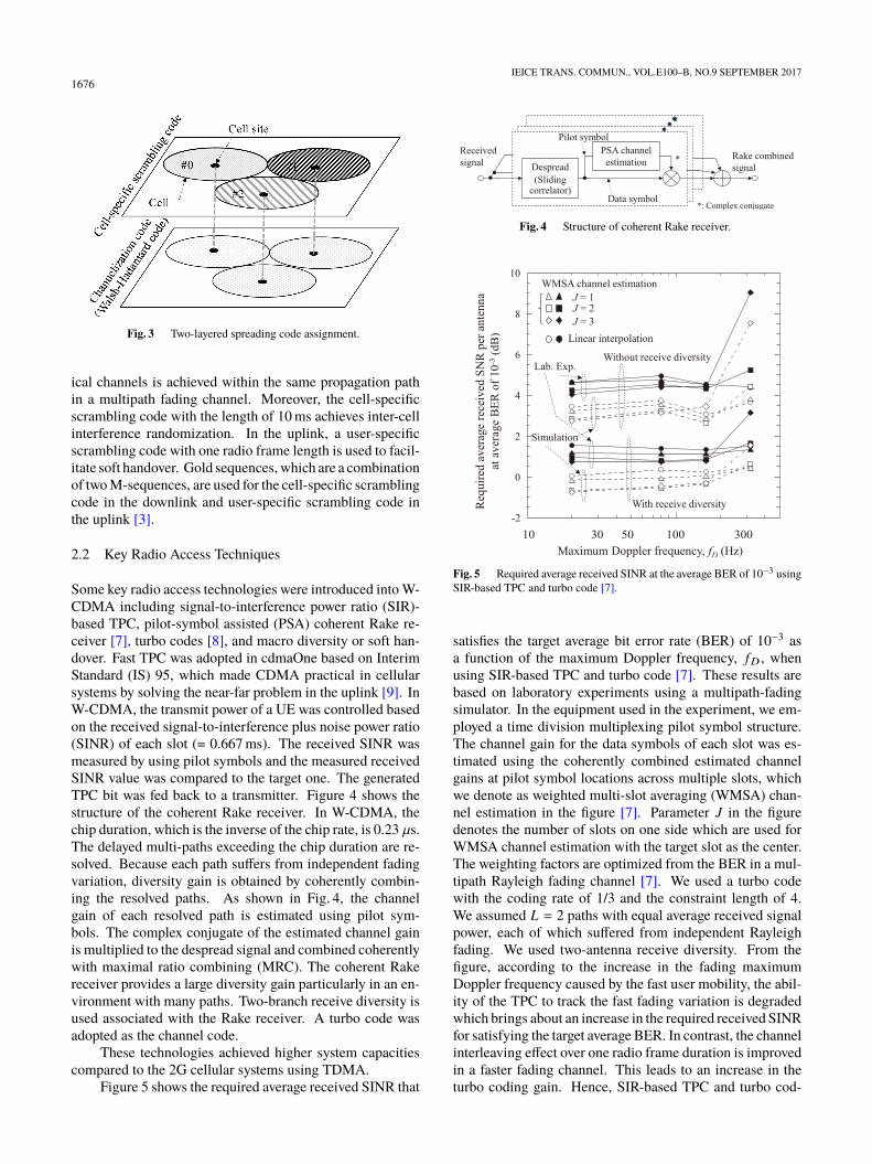
Figure 5 shows the required average received SINR that
Fig. 4 Structure of coherent Rake receiver.
Fig. 5 Required average received SINR at the average BER of 10−3 usingSIR-based TPC and turbo code [7].
satisfies the target average bit error rate (BER) of 10−3 asa function of the maximum Doppler frequency, fD , whenusing SIR-based TPC and turbo code [7]. These results arebased on laboratory experiments using a multipath-fadingsimulator. In the equipment used in the experiment, we em-ployed a time division multiplexing pilot symbol structure.The channel gain for the data symbols of each slot was es-timated using the coherently combined estimated channelgains at pilot symbol locations across multiple slots, whichwe denote as weighted multi-slot averaging (WMSA) chan-nel estimation in the figure [7]. Parameter J in the figuredenotes the number of slots on one side which are used forWMSA channel estimation with the target slot as the center.The weighting factors are optimized from the BER in a mul-tipath Rayleigh fading channel [7]. We used a turbo codewith the coding rate of 1/3 and the constraint length of 4.We assumed L = 2 paths with equal average received signalpower, each of which suffered from independent Rayleighfading. We used two-antenna receive diversity. From thefigure, according to the increase in the fading maximumDoppler frequency caused by the fast user mobility, the abil-ity of the TPC to track the fast fading variation is degradedwhich brings about an increase in the required received SINRfor satisfying the target average BER. In contrast, the channelinterleaving effect over one radio frame duration is improvedin a faster fading channel. This leads to an increase in theturbo coding gain. Hence, SIR-based TPC and turbo cod-
SAWAHASHI and HIGUCHI: RADIO ACCESS TECHNOLOGIES FOR BROADBAND MOBILE COMMUNICATIONS1677
ing associated with bit interleaving across one radio frameduration works complementarily in low-to-high mobility en-vironments up to approximately 300 km/h. We also see thatthe WMSA PSA channel estimation with J = 2 achieves a lowrequired average received SINR for low-to-high maximumDoppler frequencies up to approximately 300 Hz.
3. HSDPA and HSUPA
3.1 HSDPA
(1) Background and HSDPA radio interface [10]
When W-CDMA commercial service was launched in 2001,the amount of data traffic had been increasing remarkablydue to the spread of mobile Internet. The resource assign-ment method using a dedicated channel in W-CDMA waseffective in multiplexing low-rate physical channels carryingvoice traffic with low latency through the averaging effect ofmultiuser interference with an independent distribution. Theresource utilization efficiency of a dedicated channel was ingeneral low because it took time for physical channel setup.In addition, it was inappropriate to increase the peak datarate for data service. Moreover, resource assignment includ-ing the spreading code and transmit power was conducted ata radio network controller (RNC), not at a BS called a NodeB in W-CDMA. Accordingly, transmission delay includingthe round trip delay of automatic repeat request (ARQ) in aradio link control (RLC) sublayer in Layer 2 (L2) becamelong in W-CDMA.
Hence, in HSDPA, a shared channel called the High-Speed Downlink Shared Channel (HS-DSCH) was specifiedto carry high-speed user data efficiently. HSDPA was theenhanced transport channel of the downlink shared channelfor W-CDMA. Major radio parameters including the chiprate, transmission bandwidth, and radio frame length wereidentical to those in W-CDMA. The same radio parametersenabled the coexistence of HSDPA and W-CDMA in thesame frequency spectrum. However, a resource unit carry-ing user data was assigned every 2 ms and was referred to asthe transmission time interval (TTI). The TTI of HSDPA cor-responded to three slots in W-CDMA. The physical channelthat multiplexes the HS-DSCH was called the HS-PhysicalDownlink Shared Channel (PDSCH). The only spreadingfactor supported in the HS-PDSCH was 16. The numberof multiplexed code channels was 5, 10, and 15 at maxi-mum. The modulation schemes used were QPSK, 16QAM,and 64QAM (64QAM was added in the Rel. 7 specifica-tion). The mother coding rate of the turbo code was 1/3and coding rates higher than 1/3 were generated by punc-turing the parity bits. Soft handover was not supported forthe HS-DSCH in HSDPA. In the HSDPA radio interface,two control channels were specified: the HS-Shared Con-trol Channel (SCCH) in the downlink and the HS-DedicatedControl Channel (DPCCH) in the uplink. The HS-SCCHcarried the modulation scheme, channelization code, andUE-ID in the first part, and the redundancy and constella-
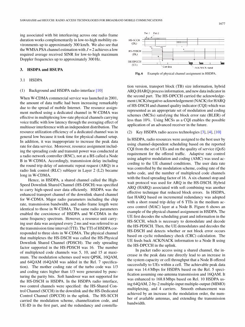
Fig. 6 Example of physical channel assignment in HSDPA.
tion version, transport block (TB) size information, hybridARQ (HARQ) process information, and new data indicator inthe second part. The HS-DPCCH carried the acknowledge-ment (ACK)/negative-acknowledgement (NACK) for HARQof HS-DSCH and channel quality indicator (CQI) which wasrepresented as an appropriate set of modulation and codingschemes (MCSs) satisfying the block error rate (BLER) ofless than 10%. Using MCSs as a CQI enables the possibleapplication of an advanced receiver in the future.
(2) Key HSDPA radio access technologies [3], [4], [10]
In HSDPA, radio resources were assigned to the best user byusing channel-dependent scheduling based on the reportedCQI from the set of UEs and on the quality of service (QoS)requirement for the offered traffic. Adaptive rate controlusing adaptive modulation and coding (AMC) was used ac-cording to the UE channel conditions. The user data ratewas controlled by the modulation scheme, coding rate of theturbo code, and the number of multiplexed code channelswith the fixed spreading factor of 16. A six-channel stop andwait protocol was used for ARQ in the HS-DSCH. HybridARQ (HARQ) associated with soft combining was anothereffective technique that reduced block errors. In HSDPA,fast HARQ based on incremental redundancy was adoptedwith a short round trip delay of 6 TTIs in the medium ac-cess control (MAC) layer at a Node B. Figure 6 shows anexample of the physical channel assignment in HSDPA. TheUE first decodes the scheduling grant and information in theHS-SCCH, which is necessary to demodulate and decodethe HS-PDSCH. Then, the UE demodulates and decodes theHS-DSCH and detects whether or not block error occursbased on cyclic redundancy check (CRC) calculation. TheUE feeds back ACK/NACK information to a Node B usingthe HS-DPCCH in the uplink.
In packet radio access using a shared channel, the in-crease in the peak data rate directly lead to an increase inthe system capacity or cell throughput that a Node B offeredsuccessfully to UEs within a cell. The achievable peak datarate was 14.4 Mbps for HSDPA based on the Rel. 5 speci-fication assuming one-antenna transmission and 16QAM. Itwas enhanced to 168.8 Mbps based on Rel. 10 HSDPA us-ing 64QAM, 2-by-2 multiple-input multiple-output (MIMO)multiplexing, and 4 carriers. Smooth enhancement wasachieved by an increase in the modulation order, the num-ber of available antennas, and extending the transmissionbandwidth.
1678IEICE TRANS. COMMUN., VOL.E100–B, NO.9 SEPTEMBER 2017
3.2 HSUPA [3], [10]
A new transport channel called the Enhanced DedicatedChannel (E-DCH) was specified for carrying user data inHSUPA. The E-DCH was multiplexed into the EnhancedDedicated Physical Data Channel (E-DPDCH). The En-hanced Dedicated Physical Control Channel (E-DPCCH)carried low layer control signals that associate with the E-DPDCH. In the uplink, wide area coverage was required withhigher priority compared to the increase in the link capac-ity. Hence, the modulation scheme was QPSK in the Rel.6 specification. The TTI length of 2 ms was added to thatof 10 ms. TPC and soft handover were used as well as theDPCH of W-CDMA. Hybrid ARQ with soft combining wasapplied. The achievable peak data rate was 5.67 Mbps withQPSK in the Rel. 6 specification and it was enhanced to22.5 Mbps using 16QAM and a 10-MHz bandwidth in theRel. 10 specification.
4. LTE
4.1 System Requirements [11], [12]
Radio access networks (RANs) that have high affinity to allInternet protocol (IP) based core networks should achieve ef-ficient multiplexing of data traffic including video messagesand download. In LTE, only packet based MA schemes em-ploying a shared channel are specified along with the voiceover IP (VoIP) capability in the packet-switching domain.Multiple scalable transmission bandwidths with a maximumof 20 MHz are specified so that LTE is deployed for theexisting frequency spectra. Low latency including a shorttransmission delay in a RAN such as less than 5 ms oneway is required. Requirements for the peak data rate are100 Mbps and 50 Mbps in the downlink and uplink, respec-tively. Higher cell throughput and cell-edge user through-put requirements are specified compared to those for Rel.5 HSDPA and Rel. 6 HSUPA in the downlink and uplink,respectively.
4.2 MA Schemes [12]–[14]
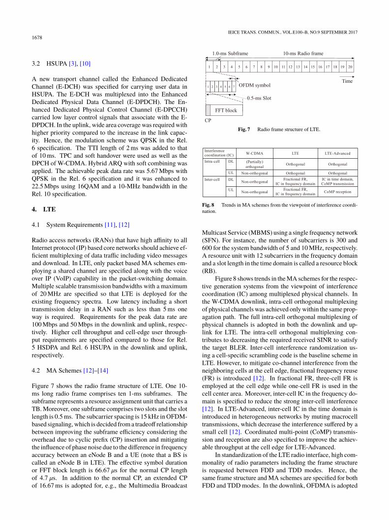
Figure 7 shows the radio frame structure of LTE. One 10-ms long radio frame comprises ten 1-ms subframes. Thesubframe represents a resource assignment unit that carries aTB. Moreover, one subframe comprises two slots and the slotlength is 0.5 ms. The subcarrier spacing is 15 kHz in OFDM-based signaling, which is decided from a tradeoff relationshipbetween improving the subframe efficiency considering theoverhead due to cyclic prefix (CP) insertion and mitigatingthe influence of phase noise due to the difference in frequencyaccuracy between an eNode B and a UE (note that a BS iscalled an eNode B in LTE). The effective symbol durationor FFT block length is 66.67 µs for the normal CP lengthof 4.7 µs. In addition to the normal CP, an extended CPof 16.67 ms is adopted for, e.g., the Multimedia Broadcast
Fig. 7 Radio frame structure of LTE.
Fig. 8 Trends in MA schemes from the viewpoint of interference coordi-nation.
Multicast Service (MBMS) using a single frequency network(SFN). For instance, the number of subcarriers is 300 and600 for the system bandwidth of 5 and 10 MHz, respectively.A resource unit with 12 subcarriers in the frequency domainand a slot length in the time domain is called a resource block(RB).
Figure 8 shows trends in the MA schemes for the respec-tive generation systems from the viewpoint of interferencecoordination (IC) among multiplexed physical channels. Inthe W-CDMA downlink, intra-cell orthogonal multiplexingof physical channels was achieved only within the same prop-agation path. The full intra-cell orthogonal multiplexing ofphysical channels is adopted in both the downlink and up-link for LTE. The intra-cell orthogonal multiplexing con-tributes to decreasing the required received SINR to satisfythe target BLER. Inter-cell interference randomization us-ing a cell-specific scrambling code is the baseline scheme inLTE. However, to mitigate co-channel interference from theneighboring cells at the cell edge, fractional frequency reuse(FR) is introduced [12]. In fractional FR, three-cell FR isemployed at the cell edge while one-cell FR is used in thecell center area. Moreover, inter-cell IC in the frequency do-main is specified to reduce the strong inter-cell interference[12]. In LTE-Advanced, inter-cell IC in the time domain isintroduced in heterogeneous networks by muting macrocelltransmissions, which decrease the interference suffered by asmall cell [12]. Coordinated multi-point (CoMP) transmis-sion and reception are also specified to improve the achiev-able throughput at the cell edge for LTE-Advanced.
In standardization of the LTE radio interface, high com-monality of radio parameters including the frame structureis requested between FDD and TDD modes. Hence, thesame frame structure and MA schemes are specified for bothFDD and TDD modes. In the downlink, OFDMA is adopted

SAWAHASHI and HIGUCHI: RADIO ACCESS TECHNOLOGIES FOR BROADBAND MOBILE COMMUNICATIONS1679
Fig. 9 Transmitter structure in OFDMA downlink.
because of its inherent immunity to multipath interference(MPI) and its support of different transmission bandwidtharrangements from 1.4 MHz to the maximum of 20 MHz.The MPI is mitigated using a low symbol rate per subcarrierand a cyclic prefix, which is appended to each fast Fouriertransform (FFT) block. Figure 9 shows the transmitter struc-ture in the OFDMA downlink. Similar to W-CDMA, a turbocode with the mother coding rate of 1/3 is adopted as thechannel coding scheme for data channels in LTE. An infor-mation data sequence called the TB is segmented and theCRC is attached. The bit sequences are turbo-encoded andrate matching is performed. After the coded bits are mappedinto a modulation symbol, channel interleaving is performed.The modulated symbols are serial-to-parallel-converted andmultiplexed with control channels. The parallel symbol se-quences are converted into OFDM signals by an inverse FFT(IFFT) followed by appending a CP and windowing.
In the uplink, SC-FDMA is adopted for its prioritiza-tion of wide area coverage provisioning due to a reductionin the transmission back-off in the transmitter power ampli-fier. Discrete Fourier transform (DFT)-spread orthogonalfrequency division multiplexing (OFDM) is adopted thatgenerates SC-FDMA signals in the frequency domain (notethat DFT-spread OFDM is also referred to as DFT-precodedOFDM) [15]. Figure 10 shows the transmitter structure forDFT-spread OFDM. By using frequency domain processing,the same radio parameters including the subcarrier spac-ing, FFT block size, and subframe length are designed forboth OFDMA and DFT-spread OFDM. In the DFT-spreadOFDM, inter-FFT block interference is mitigated by the useof a CP similar to that in downlink OFDMA. In addition,intra-FFT block interference is mitigated by using a channelequalizer. In LTE, a frequency domain equalizer (FDE) isused [15], [16]. In the FDE, the equalized weight based on,e.g., the minimum mean-square error (MMSE) criterion ismultiplied to the received subcarrier signal. In contrast, atime domain equalizer requires convolution operation of thereceived signal and the equalizer weights. Consequently, theFDE provides lower computational complexity compared tothe time domain equalizer and achieves a practical imple-mentation level for the UE.
We note that some promising technologies including in-terleave division multiple access (IDMA) [17] and OFDM/Isotropic Orthogonal Transform Algorithm (IOTA) [18]were proposed as a Study Item (SI) for LTE standardiza-tion. In the end, however, CP based OFDMA and DFT-spread OFDM were adopted. Both OFDMA and DFT-spreadOFDM need a simple one-tap equalizer or coherent detectorper subcarrier in the time and frequency domains. This re-
Fig. 10 Transmitter structure for DFT-spread OFDM.
Fig. 11 Transmission scheme for physical channel multiplexing in LTEdownlink.
sult suggests that the implementation cost particularly for aUE is another important requirement.
4.3 Physical Channel Overview
In LTE, physical channels and signals based on OFDMAand those based on SC-FDMA are specified in the LTE Rel.8 specifications. Figure 11 shows the transmission schemefor the physical channel multiplexing in the LTE downlink.In the LTE downlink, the Primary Synchronization Signal(PSS), Secondary Synchronization Signal (SSS), and Phys-ical Broadcast Channel (PBCH) are specified for the initialacquisition procedure. Both the PSS and SSS are transmittedwith a 945-kHz bandwidth from the central part of the en-tire transmission band regardless of the system bandwidth.In the LTE radio interface, 504 Physical cell IDs (PCIDs)are specified. The 504 PCIDs are divided into 168 PCIDgroups and 1 PCID group contains 3 PCIDs. The three PSSsequences correspond to three PCIDs within the same PCIDgroup. When one eNode B has a three-cell configuration,different PSS sequences are assigned to the three cells withinthat eNode B. The SSS sequences indicate 168 PCID groups.The PBCH is transmitted with a 1.08-MHz bandwidth fromthe central part of the entire transmission bandwidth and theTTI length of 40 ms. The PBCH carries the system informa-tion that is necessary for a UE to access the system. A part ofthe broadcast information including the Master InformationBlock (MIB) is also transmitted in the PBCH.
The Physical Control Format Indicator Channel (PC-FICH) indicates the number of OFDM symbols that is dy-namically reserved for control information at each subframe.The Physical Downlink Control Channel (PDCCH) is mul-
1680IEICE TRANS. COMMUN., VOL.E100–B, NO.9 SEPTEMBER 2017
Fig. 12 Contention based random access procedure in LTE uplink.
tiplexed into three OFDM symbols at maximum for eachsubframe across multiple RBs. The PDCCH carries Layer1 (L1)/L2 control signals including the RB allocation infor-mation. The Physical HARQ Indicator Channel (PHICH)indicates whether or not the uplink packet is decoded cor-rectly without error. The Physical Downlink Shared Chan-nel (PDSCH) carries user data and high-layer control sig-nals. By adopting OFDMA, the granularity in the fre-quency domain becomes much finer compared to that forW-CDMA/HSDPA with a 5-MHz transmission bandwidth.Hence, frequency domain channel-dependent scheduling isused for the PDSCH to achieve a larger multiuser diversityeffect. AMC with QPSK, 16QAM, 64QAM, 256QAM (op-tional use), and HARQ based on incremental redundancy areused for the PDSCH as well.
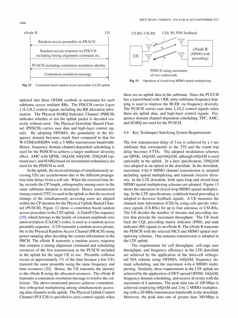
In the uplink, the received timings of simultaneously ac-cessing UEs are asynchronous due to the different propaga-tion time delays from a cell site. When the received time de-lay exceeds the CP length, orthogonality among users in thesame subframe duration is destroyed. Hence, transmissiontiming control (TTC) is used in the uplink so that the receivedtimings of the simultaneously accessing users are alignedwithin the CP duration for the Physical Uplink Shared Chan-nel (PUSCH). Figure 12 shows a contention based randomaccess procedure in the LTE uplink. A Zadoff-Chu sequence[19], which belongs to the family of constant amplitude zeroautocorrelation (CAZAC) codes, is used as a random accesspreamble sequence. A UE transmits a random access pream-ble in the Physical Random Access Channel (PRACH) usingpower ramping after decoding the system information in thePBCH. The eNode B transmits a random access responsethat contains a timing alignment command and schedulingresources of the first transmission in the PUSCH includedin the uplink for the target UE to use. Preamble collisionoccurs at approximately 1% of the time because a few UEstransmit the same preamble using the same frequency andtime resources [20]. Hence, the UE transmits the identityto the eNode B using the allocated resources. The eNode Btransmits a contention-resolution message to resolve the col-lisions. The above-mentioned process achieves contention-free orthogonal multiplexing among simultaneously access-ing data channels in the uplink. The Physical Uplink ControlChannel (PUCCH) is specified to carry control signals when
Fig. 13 Operation of closed-loop MIMO spatial multiplexing.
there are no uplink data in the subframe. Since the PUCCHhas a narrowband with 1 RB, intra-subframe frequency hop-ping is used to improve the BLER via frequency diversity.The PUSCH carries user data, L1/L2 control signals whenthere are uplink data, and high-layer control signals. Fre-quency domain channel-dependent scheduling, TPC, AMC,and HARQ are used for the PUSCH.
4.4 Key Techniques Satisfying System Requirements
The low transmission delay of 5 ms is achieved by a 1-mssubframe that corresponds to the TTI and the round tripdelay becomes 8 TTIs. The adopted modulation schemesare QPSK, 16QAM, and 64QAM, although 64QAM is usedoptionally in the uplink. In a later specification, 256QAMwas adopted as an option in the downlink. In the downlink,maximum 4-by-4 MIMO channel transmission is adoptedincluding spatial multiplexing and transmit /receive diver-sity. In the LTE downlink, both open-loop and closed-loopMIMO spatial multiplexing schemes are adopted. Figure 13shows the operation of closed-loop MIMO spatial multiplex-ing. In the LTE specifications, codebook based precoding isadopted to decrease feedback signals. A UE measures thechannel state information (CSI) by using cell-specific refer-ence signals (CS-RSs) for up to four antennas or CSI-RSs.The UE decides the number of streams and precoding ma-trix that provide the maximum throughput. The UE feedsback the CQI, precoding matrix indicator (PMI), and rankindicator (RI) signals to an eNode B. The eNode B transmitsthe PDSCH with the selected MCS and MIMO spatial mul-tiplexing schemes. One-antenna transmission is adopted inthe LTE uplink.
The requirements for cell throughput, cell-edge userthroughput, and frequency efficiency in the LTE downlinkare achieved by the application of the intra-cell orthogo-nal MA scheme using OFDMA, 64QAM, frequency do-main scheduling, and the maximum 4-by-4 MIMO multi-plexing. Similarly, these requirements in the LTE uplink areachieved by the application of DFT-spread OFDM, 16QAM,frequency-domain scheduling, and receive diversity with themaximum of 4 antennas. The peak data rate of 100 Mbps isachieved employing 64QAM and 2-by-2 MIMO multiplex-ing with a 20-MHz transmission bandwidth in the downlink.Moreover, the peak data rate of greater than 300 Mbps is
SAWAHASHI and HIGUCHI: RADIO ACCESS TECHNOLOGIES FOR BROADBAND MOBILE COMMUNICATIONS1681
achieved using 4-by-4 MIMO multiplexing associated withthe aforementioned other conditions on downlink. In theuplink, the peak data rate of 50 Mbps is achieved through a20-MHz bandwidth using 16QAM and 2-antenna receive di-versity. Moreover, the peak data rate of 75 Mbps is achievedby using 64QAM together with the same other conditions.
5. LTE-Advanced
5.1 System Requirements [20]–[22]
In the ITU-R, the system requirements for IMT-Advancedwere specified including the achievable peak data rates of100 Mbps and 1 Gbps for high mobility and low mobilityenvironments, respectively. The system requirements forLTE-Advanced were specified so that they satisfy the IMT-Advanced requirements. More specifically, the requirementfor the peak data rate is 1 Gbps and 500 Mbps in the down-link and uplink, respectively. The requirement for a highercell throughput or system capacity and that for the cell-edgeuser throughput were specified compared to those of LTE.The higher requirements are flexibly achieved by increasingthe number of available antennas for MIMO spatial divi-sion multiplexing (SDM) and the system bandwidth up to100 MHz using CA based on the same MA schemes as thosefor LTE. The approach to increase the frequency and/or spa-tial resources is very beneficial to improving the achievableperformance smoothly and flexibly based on the same MAschemes.
5.2 Carrier Aggregation (CA) [21], [22]
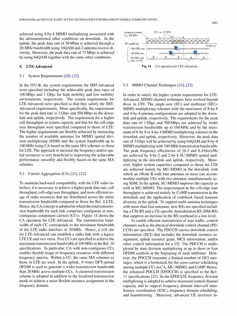
To maintain backward compatibility with the LTE radio in-terface, it is necessary to achieve a higher peak data rate, cellthroughput, cell-edge user throughput, and more efficient us-age of radio resources that are distributed across the entiretransmission bandwidth compared to those for Rel. 8 LTE.Hence, the CA concept is adopted in which the total transmis-sion bandwidth for each link comprises contiguous or non-contiguous component carriers (CCs). Figure 14 shows theCA operation for LTE-Advanced. The transmission band-width of each CC corresponds to the maximum bandwidthof the LTE radio interface or 20 MHz. Hence, a cell sitefor LTE-Advanced can establish a radio link with a legacyLTE UE and vice versa. Five CCs are specified to achieve themaximum transmission bandwidth of 100 MHz in the Rel. 10specifications. In particular, CA with non-contiguous CCsenables flexible usage of frequency resources with differentfrequency spectra. Within a CC, the same MA schemes asthose in LTE are used. In the uplink, N-times DFT-spreadOFDM is used to generate a wider transmission bandwidththan 20 MHz across multiple CCs. A clustered transmissionscheme is adopted in addition to the localized transmissionmode to achieve a more flexible resource assignment in thefrequency domain.
Fig. 14 CA operation for LTE-Advanced.
5.3 MIMO Channel Techniques [21], [22]
In order to satisfy the higher system requirements for LTE-Advanced, MIMO channel techniques have evolved beyondthose in LTE. The single-user (SU) and multiuser (MU)-MIMO multiplexing schemes with the maximum of 8-by-8and 4-by-4 antenna configurations are adopted in the down-link and uplink, respectively. The requirements for the peakdata rate of 1 Gbps and 500 Mbps are achieved by widertransmission bandwidths up to 100 MHz and by the maxi-mum of 8-by-8 or 4-by-4 MIMO multiplexing schemes in thedownlink and uplink, respectively. Moreover, the peak datarate of 3 Gbps will be achieved by using 64QAM and 8-by-8MIMO multiplexing with 100 MHz transmission bandwidth.The peak frequency efficiencies of 16.3 and 8.4 bits/s/Hzare achieved by 4-by-2 and 2-by-4 SU-MIMO spatial mul-tiplexing in the downlink and uplink, respectively. More-over, higher system capacities compared to those for LTEare achieved mainly by MU-MIMO in the downlink withwhich an eNode B with four antennas or more can accom-modate multiple UEs with two antennas simultaneously us-ing SDM. In the uplink, SU-MIMO improves the capacity aswell as MU-MIMO. The improvement in the cell-edge userthroughput is achieved mainly by CoMP transmission in thedownlink and the application of codebook based transmitdiversity in the uplink. To support multi-antenna techniqueswith more than four antennas, new RSs are specified includ-ing a CSI-RS and a UE-specific demodulation RS (DM-RS)that suppress an increase in the RS overhead to a low level.
To enable efficient transmission of user traffic, controlchannels such as the physical downlink control channel (PD-CCH) are specified. The PDCCH carries downlink controlinformation (DCI) that includes the downlink resource as-signment, uplink resource grant, MCS information, and/orother control information for a UE. The PDCCH is multi-plexed by time division multiplexing at up to three or fourOFDM symbols at the beginning of each subframe. How-ever, the PDCCH transmits a limited number of DCI mes-sages, which is a bottleneck for the cross-carrier schedulingamong multiple CCs in CA, MU-MIMO, and CoMP. Hence,the enhanced PDCCH (EPDCCH) is specified in the Re1.11 specifications [23]. In the EPDCCH, frequency divisionmultiplexing is adopted to achieve increased control channelcapacity and to support frequency domain inter-cell inter-ference coordination (ICIC), frequency domain scheduling,and beamforming. Moreover, advanced UE receivers in-
1682IEICE TRANS. COMMUN., VOL.E100–B, NO.9 SEPTEMBER 2017
cluding interference rejection combining (IRC) and low costMTC are investigated for the Rel. 11 specifications. Fulldimension (FD)-MIMO is investigated that utilizes a two-dimensional antenna array [24]. FD-MIMO forms narrowbeams to achieve MU-MIMO in the azimuth and elevationdomains. The related RSs are specified in the Rel. 13 speci-fications.
5.4 Heterogeneous Networks [21], [22]
As mentioned earlier, the system capacity has been increasedby BS densification using local cells or small cells. In theconventional local cell deployment, a local-area cell siteis a stand-alone system that operates independently from amacrocell. A local cell node has the same functions as thoseof a macrocell node such as transmission of the cell-specificRS, and system- and cell-specific control information. A UEcan connect a radio link with either a macrocell or local cell.
Heterogeneous networks (HetNets) in which a macro-cell is overlaid onto small cells or local cells including microand picocells have recently drawn attention [25], [26]. Amacrocell guarantees wide area coverage mainly focusingon the control plane and on high-mobility UEs. Hence,relatively low frequency spectra including the 2-GHz bandare anticipated to be deployed for a macrocell. Meanwhile,the small cells mainly accommodate UEs that demand high-speed data services and are under low mobility conditions.It is anticipated that a high frequency spectrum including themillimeter wave band will be used since a broad bandwidthis to be accommodated in such a high frequency spectrum.
In [27], several typical deployment scenarios for Het-Nets were specified. In the scenario using the same fre-quency spectrum for a macrocell and outdoor small cell, thecoverage area is extended compared to the cell configurationwith only a macrocell. Dynamic interference coordination inthe time domain using an almost-blank subframe is specifiedto avoid co-channel interference from a macrocell to a smallcell. The deployment scenarios using separate frequencyspectra between a macrocell and an outdoor or indoor smallcell are specified as scenarios #2a and #2b, respectively.The scenarios employing separate frequency spectra providemore flexible deployment of small cells in an area with hightraffic demand compared to those using the same frequencyspectrum because they do not suffer from mutual co-channelinterference.
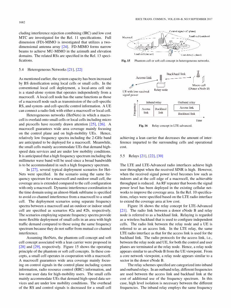
Assuming HetNets, the phantom cell concept and softcell concept associated with a lean carrier were proposed in[28] and [29], respectively. Figure 15 shows the operatingprinciple of the phantom or soft cell concepts. In these con-cepts, a small cell operates in cooperation with a macrocell.A macrocell guarantees wide area coverage mainly focus-ing on control signals in the control plane including systeminformation, radio resource control (RRC) information, andlow-rate user data for high-mobility users. The small cellsmainly accommodate UEs that demand high-speed data ser-vices and are under low mobility conditions. The overheadof the RS and control signals is decreased for a small cell
Fig. 15 Phantom cell or soft cell concept in heterogeneous networks.
Fig. 16 Relay concept in LTE-advanced.
achieving a lean carrier that decreases the amount of inter-ference imparted to the surrounding cells and operationalcost.
5.5 Relays [21], [22], [30]
The LTE and LTE-Advanced radio interfaces achieve highuser throughput when the received SINR is high. However,when the received signal power level becomes low such asindoors and at the cell edge of a macrocell, the achievablethroughput is reduced. An RF repeater that boosts the signalpower level has been deployed in the existing cellular net-works to improve the coverage area. In the Rel. 10 specifica-tions, relays were specified based on the LTE radio interfaceto extend the coverage area at low cost.
Figure 16 shows the relay concept for LTE-Advanced[21]. The radio link between a donor eNode B and relaynode is referred to as a backhaul link. Relaying is regardedas a wireless backhaul that is used to configure independentcells. The radio link between the relay node and a UE isreferred to as an access link. In the LTE relay, the sameLTE radio interface as that for the access link is used for thebackhaul link. The radio protocols for the access link, i.e.,between the relay node and UE, for both the control and userplanes are terminated at the relay node. Hence, a relay nodeappears similar to an eNode B from the UE viewpoint. Froma core network viewpoint, a relay node appears similar to asector in the donor eNode B.
The relay schemes specified are categorized into inbandand outband relays. In an outband relay, different frequenciesare used between the access link and backhaul link at thecost of additional use of the frequency spectrum. In thiscase, high level isolation is necessary between the differentfrequencies. The inband relay employs the same frequency
SAWAHASHI and HIGUCHI: RADIO ACCESS TECHNOLOGIES FOR BROADBAND MOBILE COMMUNICATIONS1683
for both the access link and backhaul link. In this case, thereis no interference between the backhaul link and access linkbecause these links are separated in the time domain. Incontrast, the transmission delay in the inband relay is longercompared to that in the outband relay.
The Multicast Broadcast Single Frequency Network(MBSFN) subframe for the MBMS is used for data trans-mission in a backhaul link from a donor eNodeB to a relaynode. Moreover, a new control channel called the RelayPDCCH (R-PDCCH) is specified as a backhaul link that ismultiplexed after the PDCCH.
5.6 CoMP [21], [31], [32]
When using soft handover in the downlink adopted forW-CDMA, multiple physical channels with different cell-specific scrambling codes are transmitted from multiple cellsites, i.e., eNode Bs. However, due to the mutual interferenceamong the simultaneously transmitted channels, the macrodiversity gain is limited in the downlink. Moreover, soft han-dover requires an increase in the implementation complexityof a higher layer node such as RNC and that of a UE. Hence,soft handover is not adopted due to the small macro diver-sity gain and high implementation complexity and signalingoverhead in LTE. The improvement in the cell-edge userthroughput is still one of the most important system require-ments for LTE with one-cell frequency reuse as a baseline.To improve the cell-edge user throughput, the usage of powerresources of multiple cell sites is the most effective method.Hence, CoMP transmission and reception are investigatedand the related signaling is specified in the Rel. 11 radiointerface.
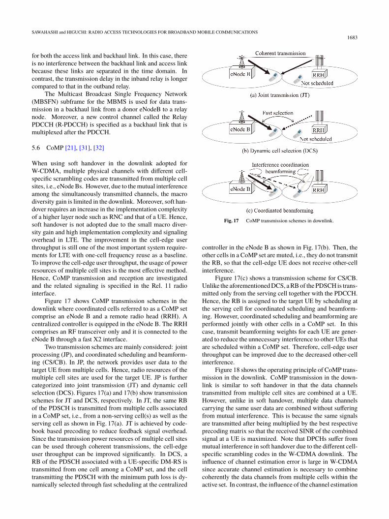
Figure 17 shows CoMP transmission schemes in thedownlink where coordinated cells referred to as a CoMP setcomprise an eNode B and a remote radio head (RRH). Acentralized controller is equipped in the eNode B. The RRHcomprises an RF transceiver only and it is connected to theeNode B through a fast X2 interface.
Two transmission schemes are mainly considered: jointprocessing (JP), and coordinated scheduling and beamform-ing (CS/CB). In JP, the network provides user data to thetarget UE from multiple cells. Hence, radio resources of themultiple cell sites are used for the target UE. JP is furthercategorized into joint transmission (JT) and dynamic cellselection (DCS). Figures 17(a) and 17(b) show transmissionschemes for JT and DCS, respectively. In JT, the same RBof the PDSCH is transmitted from multiple cells associatedin a CoMP set, i.e., from a non-serving cell(s) as well as theserving cell as shown in Fig. 17(a). JT is achieved by code-book based precoding to reduce feedback signal overhead.Since the transmission power resources of multiple cell sitescan be used through coherent transmissions, the cell-edgeuser throughput can be improved significantly. In DCS, aRB of the PDSCH associated with a UE-specific DM-RS istransmitted from one cell among a CoMP set, and the celltransmitting the PDSCH with the minimum path loss is dy-namically selected through fast scheduling at the centralized
Fig. 17 CoMP transmission schemes in downlink.
controller in the eNode B as shown in Fig. 17(b). Then, theother cells in a CoMP set are muted, i.e., they do not transmitthe RB, so that the cell-edge UE does not receive other-cellinterference.
Figure 17(c) shows a transmission scheme for CS/CB.Unlike the aforementioned DCS, a RB of the PDSCH is trans-mitted only from the serving cell together with the PDCCH.Hence, the RB is assigned to the target UE by scheduling atthe serving cell for coordinated scheduling and beamform-ing. However, coordinated scheduling and beamforming areperformed jointly with other cells in a CoMP set. In thiscase, transmit beamforming weights for each UE are gener-ated to reduce the unnecessary interference to other UEs thatare scheduled within a CoMP set. Therefore, cell-edge userthroughput can be improved due to the decreased other-cellinterference.
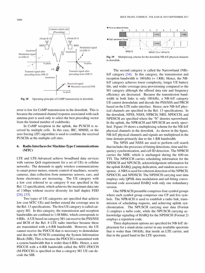
Figure 18 shows the operating principle of CoMP trans-mission in the downlink. CoMP transmission in the down-link is similar to soft handover in that the data channelstransmitted from multiple cell sites are combined at a UE.However, unlike in soft handover, multiple data channelscarrying the same user data are combined without sufferingfrom mutual interference. This is because the same signalsare transmitted after being multiplied by the best respectiveprecoding matrix so that the received SINR of the combinedsignal at a UE is maximized. Note that DPCHs suffer frommutual interference in soft handover due to the different cell-specific scrambling codes in the W-CDMA downlink. Theinfluence of channel estimation error is large in W-CDMAsince accurate channel estimation is necessary to combinecoherently the data channels from multiple cells within theactive set. In contrast, the influence of the channel estimation
1684IEICE TRANS. COMMUN., VOL.E100–B, NO.9 SEPTEMBER 2017
Fig. 18 Operating principle of CoMP transmission in downlink.
error is low for CoMP transmission in the downlink. This isbecause the estimated channel response associated with eachantenna port is used only to select the best precoding vectorfrom the limited number of codebooks.
In CoMP reception in the uplink, the PUSCH is re-ceived by multiple cells. In this case, IRC, MMSE, or thezero forcing (ZF) algorithm is used to combine the receivedPUSCHs at the multiple cell sites.
6. Radio Interfaces for Machine-Type Communications(MTC)
LTE and LTE-Advanced achieve broadband data serviceswith various QoS requirements for a set of UEs in cellularnetworks. The demands to apply wireless communicationsto smart power meters, remote control of machines, securitycameras, data collection from numerous sensors, cars, andhome electronics are increasing. The UE category witha low cost referred to as category 0 was specified in theRel. 12 specification, which achieves the maximum data rateof 1 Mbps without receive diversity for half duplex FDD[24], [33].
Two types of UE categories are specified that achievelow cost MTC UEs and further extend the coverage area inthe Rel. 13 specifications. The first UE category is called cat-egory M1. In this category, the transmission and receptionbandwidths are confined to 1.08 MHz, which corresponds to6 RBs. A UE based on category M1 can receive the PSS/SSSand BCH of the Rel. 8 LTE radio interface because theseare transmitted with a 6-RB bandwidth. However, the UEcannot receive the PDCCH that is necessary to demodulateand decode the PUSCH containing the System InformationBlock (SIB). This is because the PDCCH is transmitted witha system bandwidth that is wider than 6 RBs. Hence, a newPDCCH with a 6-RB bandwidth called the MTC-PDCCH(M-PDCCH) is specified so that a category M1 UE can de-code the SIB.
Fig. 19 Multiplexing scheme for the downlink NB-IoT physical channelsin downlink.
The second category is called the Narrowband (NB)-IoT category [34]. In this category, the transmission andreception bandwidth is 180 kHz (= 1 RB). Hence, the NB-IoT category achieves lower complexity, longer UE batterylife, and wider coverage-area provisioning compared to theM1 category although the offered data rate and frequencyefficiency are decreased. Because the transmission band-width in both links is only 180 kHz, a NB-IoT categoryUE cannot demodulate and decode the PSS/SSS and PBCHbased on the LTE radio interface. Hence, new NB-IoT phys-ical channels are specified in the Rel. 13 specifications. Inthe downlink, NPSS, NSSS, NPBCH, NRS, NPDCCH, andNPDSCH are specified where the “N” denotes narrowband.In the uplink, the NPRACH and NPUSCH are newly speci-fied. Figure 19 shows a multiplexing scheme for the NB-IoTphysical channels in the downlink. As shown in the figure,NB-IoT physical channels and signals are multiplexed in thetime domain primarily due to the 1-RB bandwidth.
The NPSS and NSSS are used to perform cell searchthat includes the processes of timing detections, time and fre-quency synchronization, and cell ID detection. The NPBCHcarries the MIB, which is unchanged during the 640-msTTI. The NPDCCH carries scheduling information for theNPDSCH and NPUSCH, acknowledgement information forthe uplink HARQ, paging dedication, and random access re-sponse. A NRS is used for coherent detection of the NPBCH,NPDCCH, and NPDSCH. The NPDSCH carrying user dataemploys only QPSK data modulation and tail-biting convo-lutional code associated HARQ with only one redundancyversion.
One NPRACH preamble comprises four symbol groupswhere each symbol group comprises one CP and five sym-bols. The NPRACH is used to establish a radio link, trans-mission of scheduling requests, and achieving uplink syn-chronization. The NPUSCH carrying user data (Format1) employs a turbo code, while the NPUSCH carrying ac-knowledge signaling of HARQ for the NPDSCH (Format 2)employs a repetition code.
Three deployment options are specified for NB-IoT: de-ployment for a stand-alone carrier in any available spectrumthat is wider than 180 kHz, that inside an LTE carrier, andthat in the guard band in the LTE spectrum.
SAWAHASHI and HIGUCHI: RADIO ACCESS TECHNOLOGIES FOR BROADBAND MOBILE COMMUNICATIONS1685
7. 5G Cellular Systems
7.1 System Requirements
The SI investigation for a new radio interface for 5G cellularsystems has been initiated in the 3GPP. The SI aims at de-veloping a single technical frame work that addresses usagescenarios including enhanced mobile broadband (eMBB),massive MTC, and ultra-reliable low latency communica-tions (URLLC) [35], [36]. 5G radio access networks willprovide broadband services with the user rate of a few giga-bits per second at maximum. The aggregated peak data rateof a shared channel will be higher than a few tens of gigabitsper second. Moreover, it is desirable for the peak data rateto be enhanced to near 100 Gbps based on the same radio in-terface by increasing the number of available antennas in thespatial domain and transmission bandwidth in the frequencydomain. Another important requirement is to support MTCtraffic flows for IoT in which all kinds of devices includ-ing factory machines, automobiles, home electronics, andsensors are connected to the Internet. Remote control op-eration for massive IoT traffic flows is possible by using thewireless channel with low latency. In particular, extremelylow latency such as 1 ms is necessary for the application tomission-critical data such as automobiles. Meanwhile, ex-tremely low power consumption is needed for sensor devices.
7.2 OFDM Based MA Schemes
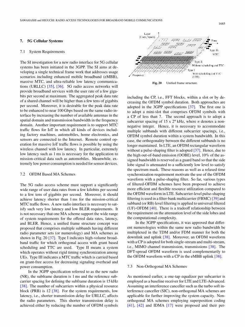
The 5G radio access scheme must support a significantlywide range of user data rates from a few kilobits per secondto a few tens of gigabits per second. Moreover, it shouldachieve latency shorter than 1 ms for the mission-criticalMTC traffic flows. A new radio interface is necessary to sat-isfy such very low latency and low BLER requirements. Itis not necessary that one MA scheme support the wide rangeof system requirements for the offered data rates, latency,and BLER. Hence, a unified frame structure concept wasproposed that comprises multiple subbands having differentradio parameter sets (or numerology) and MA schemes asshown in Fig. 20 [37]. Type I indicates high-volume broad-band traffic for which orthogonal access with grant basedscheduling and TTC are used. Type II means a systemwhich operates without rigid timing synchronization amongUEs. Type III indicates a MTC traffic which is carried basedon grant-free access for decreasing signaling overhead andpower consumption.
In the 3GPP specification referred to as the new radio(NR), the subframe duration is 1 ms and the reference sub-carrier spacing for defining the subframe duration is 15 kHz[38]. The number of subcarriers within a physical resourceblock (PRB) is 12 [38]. For the system requirements, lowlatency, i.e., shorter transmission delay for URLLC, affectsthe radio parameters. This shorter transmission delay isachieved either by reducing the number of OFDM symbols
Fig. 20 Unified frame structure.
including the CP, i.e., FFT blocks, within a slot or by de-creasing the OFDM symbol duration. Both approaches areadopted in the 3GPP specifications [37]. The first one isto adopt a mini-slot that comprises OFDM symbols witha CP of less than 7. The second approach is to adopt asubcarrier spacing of 15 x 2n kHz, where n denotes a non-negative integer. Hence, it is necessary to accommodatemultiple subbands with different subcarrier spacings, i.e.,OFDM symbol duration within a system bandwidth. In thiscase, the orthogonality between the different subbands is nolonger maintained. In LTE, an OFDM rectangular waveformwithout a pulse-shaping filter is adopted [37]. Hence, due tothe high out-of-band emission (OOBE) level, 10% of the as-signed bandwidth is reserved as a guard band so that the sidelobe signal is attenuated to a sufficiently low level to satisfythe spectrum mask. These reasons as well as a relaxed timesynchronization requirement motivate the use of the OFDMwaveform with a pulse-shaping filter. So far, various typesof filtered-OFDM schemes have been proposed to achievemore efficient and flexible resource utilization compared tothe OFDM waveform in LTE. Subcarrier-level pulse-shapingfiltering is used in a filter-bank multicarrier (FBMC) [39] andsubband (or RB) level filtering is applied to universal filtered(UF)-OFDM [40]. There is a tradeoff relationship betweenthe requirement on the attenuation level of the side lobes andthe computational complexity.
In the 3GPP specifications, it was approved that differ-ent numerologies within the same new radio bandwidth bemultiplexed in the TDM and/or FDM manner for both thedownlink and uplink [38]. Moreover, an OFDM waveformwith a CP is adopted for both single-stream and multi-stream,i.e., MIMO channel transmission, transmissions [38]. TheDFT-spread OFDM waveform is used complementarily tothe OFDM waveform with a CP in the eMBB uplink [38].
7.3 Non-Orthogonal MA Schemes
As mentioned earlier, a one-tap equalizer per subcarrier isemployed as a baseline receiver for LTE and LTE-Advanced.Assuming an interference canceller such as the turbo soft in-terference canceller (SIC), non-orthogonal MA schemes areapplicable for further improving the system capacity. Non-orthogonal MA schemes employing superposition coding[41], [42] and IDMA [17] were proposed and their per-
1686IEICE TRANS. COMMUN., VOL.E100–B, NO.9 SEPTEMBER 2017
formance improvements in terms of the system capacitywere reported. Moreover, non-orthogonal multiplexing orhigh-density packing of data symbols on resource elements,which is referred to as Faster-than-Nyquist (FTN), was pro-posed and its throughput improvements were investigated[43], [44]. It is considered that non-orthogonal MA andmultiplexing schemes are effective in improving the systemcapacity for a small cell with a high offered traffic load.
In the uplink, non-orthogonal MA schemes were pro-posed that do not use grant-based resource assignment andtight transmission timing control to achieve a very short la-tency. A CDMA scheme using a low density signature (LDS)called LDS-CDMA was proposed for multiplexing massivephysical channels with a low data rate [45]. Moreover, spacecode multiple access (SCMA) achieves direct mapping ofcoded bits to multi-dimensional codewords that correspondsto the symbol mapping and spreading with LDS [46]. Bothschemes employ a message-passing algorithm (MPA) withlow computational complexity at a receiver. In the 3GPP,MA schemes with low cross-correlation codes including aLDS and Zadoff-Chu sequence [19] were proposed [38].
From the application of non-orthogonal MA schemes,commonality with the existing orthogonal MA schemes isdesirable in the same frequency spectrum. Moreover, atransparent channel in a higher layer must be multiplexedin the same way as that for orthogonal MA schemes. In5G systems, the number of antennas will be increased toincrease the beamforming gain and multiplexing gain [47].In addition, the system bandwidth will become wider by tak-ing advantage of CA or spectrum aggregation. According tothe increases in the number of antennas and the bandwidth,the number of the overhead signals including RSs for CSImeasurement and feedback signals will be increased. TDDis more beneficial in reducing the number of the overheadsignals compared to FDD by taking advantage of channelreciprocity.
8. Conclusion
In this paper, we presented the MA technologies for W-CDMA, HSDPA/HSUPA, LTE, and LTE-Advanced. Wealso described the requirements, envisioned challenges, andMA technology candidates for the future 5G systems.
In the 3GPP, the system requirements are specified first.The best radio access techniques and numerology are speci-fied so that the system requirements are satisfied. This stan-dardization process leads to the development of an excellentradio interface. The conventional cellular systems suggestthat major technical pillars are almost identical regardless ofthe radio access systems of the respective generation. Hence,according to the system requirements, the development of thekey pillar technology is important. For the future 5G cel-lular systems, MTC, which will carry IoT traffic flows withvery low latency and high quality will be another promisingrequirement in addition to the eMBB. Technologies that pro-vide the best performance considering the overhead of theRSs and control signals are desirable. Forward compatibil-
ity or smooth enhancement of the achievable performanceby extending the transmission bandwidth and/or number ofantennas is a promising approach assuming the same MAschemes and frame structure. Backward compatibility isalso an important requirement from the viewpoint of reduc-ing the network cost.
Acknowledgements
We extend our sincere appreciation Prof. M. Taromaru ofFukuoka University, former Chair of RCS Committee andProf. H. Murata of Kyoto University, Chair of RCS Commit-tee for giving us this opportunity to contribute to the specialissue of this transaction. This work is partially supported byJSPS KAKENHI Grant Number 16H04368.
References
[1] K. Tachikawa, W-CDMA Mobile Communications, Maruzen, 2001(in Japanese).
[2] https://en.wikipedia.org/wiki/Motorola_MicroTAC[3] 3GPP TS25.211 (V12.2.0), “Physical channels and mapping of trans-
port channels onto physical channels (FDD),” Sept. 2016.[4] F. Adachi, M. Sawahashi, and K. Okawa, “Tree-structured generation
of orthogonal spreading codes with different lengths for forward linkDS-CDMA mobile radio,” IEE Electron. Lett., vol.33, no.1, pp.27–28, Jan. 1997.
[5] 3GPP TS25.212 (V12.2.0), “Multiplexing and channel coding(FDD),” June 2016.
[6] H. Holma and A. Toskala, WCDMA for UMTS, Third Edition, JohnWiley & Sons, 2004.
[7] K. Higuchi, H. Andoh, K. Okawa, M. Sawahashi, and F. Adachi,“Experimental evaluation of combined effect of coherent rake com-bining and SIR-based fast transmit power control for reverse link ofDS-CDMA mobile radio,” IEEE J. Select. Areas Commum., vol.18,no.8, pp.1526–1535, Aug. 2000.
[8] C. Berrou and A. Glavieux, “Near optimum error correcting codingand decoding: Turbo codes,” IEEE Trans. Commun., vol.44, no.10,pp.1261–1271, Oct. 1996.
[9] TIA/EIA/IS-95-A, Interim Standard: Mobile Station-Base StationCompatibility Standard for Dual-Mode Wideband Spread SpectrumCellular Systems, Telecommunications Industry Association, May1995.
[10] H. Holma and A. Toskala, HSDPA/HSUPA for UMTS, John Wiley& Sons, 2006.
[11] 3GPP Technical Report, TR25.913 (V7.0.0), “Requirements forevolved UTRA (E-UTRA) and evolved UTRAN (E-UTRAN),” June2005.
[12] H. Holma and A. Toskala, LTE for UMTS, Evolution to LTE-Advanced, John Wiley & Sons, 2011.
[13] 3GPP TS36.211 (V13.3.0), “Evolved universal terrestrial radio ac-cess (E-UTRA); Physical channels and modulation,” Sept. 2016.
[14] 3GPP TS36.212 (V13.3.0), “Evolved universal terrestrial radio ac-cess (E-UTRA); Multiplexing and channel coding,” Sept. 2016.
[15] H. Sari, G. Karam, and I. Jeanclaude, “Frequency-domain equaliza-tion of mobile radio and terrestrial broadcast channels,” Proc. IEEEGlobecom, vol.1, pp. 1–5, Nov.-Dec. 1994.
[16] D. Falconer, S.L. Ariyavistakul, A. Benyamin-Seeyar, and B. Edison,“Frequency domain equalization for single-carrier broadband wire-less systems,” IEEE Commun. Mag., vol.40, no.4, pp.58–66, April2002.
[17] L. Liu, J. Tong, and Li Ping, “Analysis and optimization of CDMAsystems with chip-level interleavers,” IEEE J. Sel. Areas Commun.,vol.24, no.1, pp.141–150, Jan. 2006.
SAWAHASHI and HIGUCHI: RADIO ACCESS TECHNOLOGIES FOR BROADBAND MOBILE COMMUNICATIONS1687
[18] J.-P. Javaudin and P.-J. Bouvet, “Use of signals in quadrature overOFDM/OQAM,” Proc. IEEE VTC2007-Spring, pp.1891–1895, May2007.
[19] D.C. Chu, “Polyphase codes with good periodic correlation prop-erties,” IEEE Trans. Inf. Theory, vol.IT-18, no.4, pp.531–532, July1972.
[20] 3GPP Technical Report, TR36.913 (V8.0.1), “Requirements for fur-ther advancements for evolved UTRA (E-UTRA) (LTE-advanced),”March 2009.
[21] H. Holma and A. Toskala, LTE-Advanced, John Wiley & Sons, 2012.[22] E. Dahlman, S. Parkvall, and J. Skold, 4G LTE/LTE-Advanced for
Mobile Broadband, Academic Press, 2011.[23] S. Ye, S.H. Wang, and C. Worrall, “Enhanced physical downlink
control channel in LTE advanced release 11,” IEEE Commun. Mag.,vol.51, no.2, pp.82–89, Feb. 2013.
[24] J. Lee, Y. Kim, Y. Kwak, J. Zhang, A. Papasakellariou, T. Novlan,C. Sun, and Y. Li, “LTE-advanced in 3GPP Rel-13/14: An evolu-tion toward 5G,” IEEE Commun. Mag., Communications StandardsSupplement, vol.54, no.3, pp.36–42, March 2016.
[25] A. Damnjanovic, J. Montojo, W. Yongbin, J. Tingfang, L. Tao, M.Vajapeyam, Y. Taesang, S. Osok, and D. Malladi, “A survey on3GPP heterogeneous networks,” IEEE Wireless Commun., vol.17,no.3, pp.10–21, June 2011.
[26] 3GPP TR36.932 (V12.1.0), “Scenarios and requirements for smallcell enhancements for E-UTRA and E-UTRAN,” March 2013.
[27] 3GPP TR36.872 (V12.1.0), “Small cell enhancements for E-UTRAand E-UTRAN – Physical layer aspects,” Dec. 2013.
[28] 3GPP RWS-120010, “Requirements, candidate solutions & technol-ogy roadmap for LTE Rel-12 onward,” NTT DOCOMO, June 2012.
[29] 3GPP RWS-120003, “LTE release 12 and beyond,” Ericsson, June2012.
[30] C. Hoymann, W. Chen, J. Montojo, and A. Golitschek, C. Koutsima-nis, and X. Shen, “Relaying operation in 3GPP LTE: Challenges andsolutions,” IEEE Commun. Mag., vol.50, no.2, pp.156–162, Feb.2012.
[31] S. Geirhofer and P. Gall, “Coordinated multi point transmission in3GPP LTE heterogeneous networks,” Proc. IEEE Globecom work-shop, Dec. 2012.
[32] D. Lee, H. Seo, B. Clerckx, E. Hardouin, D. Mazzarese, S. Nagata,and K. Sayana, “Coordinated multipoint transmission and recep-tion in LTE-advanced: Deployment scenarios and operational chal-lenges,” IEEE Commun. Mag., vol.50, no.2, pp.148–155, Feb. 2012.
[33] D. Astely, E. Dahlman, G. Fodor, S. Parkvall, and J. Sachs, “LTErelease 12 and beyond,” IEEE Commun. Mag., vol.51, no.7, pp.154–160, July 2013.
[34] Y.-P. Eric Wang, X. Lin, A. Adhikary, A. Grövlen, Y. Sui, Y. Blanken-ship, J. Bergman, and H.S. Razaghi, “A primer on 3GPP narrowbandInternet of things,” IEEE Commun. Mag., vol.55, no.3, pp.117–123,March 2017.
[35] E. Dahlman, G. Mildh, S. Parkvall, J. Peisa, J. Sachs, Y. Selen, andJ. Skold, “5G wireless access: Requirements and realization,” IEEECommun. Mag., Communications Standards Supplement, vol.52,no.12, pp.42–47, Dec. 2014.
[36] T. Nakamura, A. Benjebbour, Y. Kishiyama, S. Suyama, and T. Imai,“5G radio access: Requirements, concept and experimental trials,”IEICE Trans. Commun., vol.E98-B, no.8, pp.1397–1406, Aug. 2015.
[37] G. Wunder, P. Jung, M. Kasparick, T. Wild, F. Schaich, Y. Chen, S.T.Brink, I. Gaspar, N. Michailow, A. Festag, L. Mendes, N. Cassiau,D. Ktenas, M. Dryjanski, S. Pietrzyk, B. Eged, P. Vago, and F.Wiedmann, “5GNOW: Non-orthogonal, asynchronous waveformsfor future mobile applications,” IEEE Commun. Mag., vol.52, no.2,pp.97–105, Feb. 2014.
[38] 3GPP TR 38.802 (V1.1.0) “Study on new radio (NR) access tech-nology, physical layer aspects,” Jan. 2017.
[39] B.F.-Boroujeny, “OFDM versus filter bank multicarrier,” IEEE Sig-nal Process. Mag., vol.28, no.3, pp.92–112, May 2011.
[40] T. Wild, F. Schaich, and Y. Chen, “5G air interface, design based on
universal filtered (UF-) OFDM,” Proc. International Conf. on DSP,Aug. 2014.
[41] D. Tse and P. Viswanath, Fundamentals of Wireless Communica-tions, Cambridge University Press, 2005.
[42] K. Higuchi and A. Benjebbour, “Non-orthogonal multiple access(NOMA) with successive interference cancellation for future ra-dio access,” IEICE Trans. Commun., vol.E98-B, no.3, pp.403–414,March 2015.
[43] J.E. Mazo, “Faster-than-Nyquist signaling,” Bell Syst. Techn. J.,vol.54, no.8, pp.1257–1264, Oct. 1975.
[44] D. Dasalukunte, F. Rusek, and V. Owall, “Multicarrier faster-than-Nyquist signaling transceivers: Hardware architecture and perfor-mance analysis,” IEEE Trans. Circuits Syst. I (TCAS-I), vol.58, no.4,pp.827–838, April 2011.
[45] R. Hoshyar, F.P. Wathan, and R. Tafazolli, “Novel Low-density sig-nature for synchronous CDMA systems over AWGN channel,” IEEETrans. Signal Process., vol.56, pp.1616–1626, April 2008.
[46] H. Nikopour and H. Baligh, “Sparse code multiple access,” Proc.IEEE PIMRC2013, Sept. 2013.
[47] F. Rusek, D. Persson, B.K. Lau, E.G. Larsson, T.L. Marzetta, O.Edfors, and F. Tufvesson, “Scaling up MIMO,” IEEE Signal. Process.Mag., vol.30, no.1, pp.40–60, Jan. 2013.
Mamoru Sawahashi received his B.S. andM.S. degrees from Tokyo University in 1983and 1985, respectively, and received his Dr.Eng.Degree from the Nara Institute of Technologyin 1998. In 1985, he joined the NTT Electri-cal Communications Laboratories, and in 1992he transferred to NTT Mobile CommunicationsNetwork, Inc. (now NTT DOCOMO, INC.). InNTT, he was engaged in the research of modula-tion/demodulation techniques for mobile radio.He was also engaged in the research and devel-
opment of radio access technologies for W-CDMA mobile communicationsand broadband packet radio access technologies for 3G long-term evolutionand for the systems beyond IMT-2000 in NTT DOCOMO. From April 2006,he assumed the position of Professor of the Department of Electronics andCommunication Engineering, Musashi Institute of Technology. From 2007,he has been a part-time director of the Radio Access Development Depart-ment of NTT DOCOMO. In 2005 and 2006, he served as a guest editor ofthe IEEE JSAC on Intelligent Services and Applications in Next-generationNetworks, 4G Wireless Systems, and Advances in Multicarrier CDMA.
Kenichi Higuchi received the B.E. de-gree from Waseda University, Tokyo, Japan, in1994, and received the Dr.Eng. degree from To-hoku University, Sendai, Japan in 2002. In1994, he joined NTT Mobile CommunicationsNetwork, Inc. (now, NTT DOCOMO, INC.).In NTT DOCOMO, INC., he was engaged inthe research and standardization of wireless ac-cess technologies for wideband DS-CDMA mo-bile radio, HSPA, LTE, and broadband wirelesspacket access technologies for systems beyond
IMT-2000. In 2007, he joined Tokyo University of Science. He is currentlyan Professor at Tokyo University of Science. His current research interestsare in the areas of wireless technologies and mobile communication systems,including advanced multiple access, radio resource allocation, inter-cell in-terference coordination, multiple-antenna transmission techniques, signalprocessing such as interference cancellation and turbo equalization, andissues related to heterogeneous networks using small cells. He is a memberof the IEICE and IEEE.