Embed Size (px)
Citation preview
Radian Research, Inc.3852 Fortune DriveLafayette, IN 47905 USATel: 765-449-5500Fax: 765-448-4614www.radianresearch.com
Oper
atio
ns M
anua
l
Radian Research, Inc.
Model 453UTEC Portable WHM Test Kit
Copyright Radian Research, Inc., All Rights Reserved. 453 Manual Rev 5, 100906 1
MODEL 453 PORTABLE WATTHOUR METER TEST KIT ............................ 3 APPLICATION ................................................................................................ 3 FEATURES ..................................................................................................... 3 SPECIFICATIONS ........................................................................................... 4 TEST CABLES ................................................................................................ 5
TEST CABLES FOR USE WITH "SWITCHED POTENTIAL" STANDARDS LIKE SCIENTIFIC COLUMBUS SC-10, GE IB-10, SANGAMO J44, ETC. ............... 5 TEST CABLES FOR USE WITH SCIENTIFIC COLUMBUS SC-10V, 20, 30, RADIAN RM-10, 12, 16, RD-20, RD-21 OR SCHLUMBERGER A-7 ............... 5
FRONT PANEL CONTROLS ................................................................................ 6 CURRENT CONTROL ........................................................................... 7 VOLTAGE .......................................................................................... 8 GROUND .......................................................................................... 8
UNDERSTANDING THE RADIAN RESEARCH, INC. TEST CABLE .............................. 9 EKSTROM `S' BASE TEST ADAPTERS .................................................... 9 MULTI-AMP `S' BASE TEST ADAPTERS.................................................. 9
TEST CONNECTIONS .................................................................................... 11 TEST PROCEDURE ........................................................................................ 14
TESTING SELF-CONTAINED SOCKET BASE WATTHOUR METERS. (Forms 1, 2, 12, 13, 14, 15 and 16) ................................................................. 14 TESTING TRANSFORMER RATED SOCKET BASE WATTHOUR METERS. (FORMS 3, 4, 5, 6, 8, 9 AND 10) ........................................................ 16 TESTING BOTTOM CONNECTED WATTHOUR METERS ............................ 20 TESTING WATTHOUR METERS IN THE FIELD USING A PHOTO PICK-UP ... 20
CALCULATION OF TEST ACCURACY WHEN USING REFERENCE STANDARDS THAT READ IN WATTHOURS................................................................................... 20 DISASSEMBLY OF THE MODEL UTEC 453 ......................................................... 21 SERVICE ..................................................................................................... 22
WARRANTY SERVICE ........................................................................ 22 AFTER WARRANTY SERVICE .............................................................. 22
LIMITED PRODUCT WARRANTY .......................................................... 24 ANSI C12.10 Meter Connection Chart ................................................. 25 INTRODUCTION TO WATTHOUR METER TESTING ............................... 44

Copyright Radian Research, Inc., All Rights Reserved. 453 Manual Rev 5, 100906 2
CAUTION
READ THIS NOTE
The operation and application of the Model UTEC 453 Portable Watthour Meter Test Kit requires experience and training in the skills of electric meter testing. The information in this manual is designed to supplement existing knowledge and experience already attained and practiced by journeyman level meter test technicians. Beginning meter test technicians should not attempt to operate this equipment without first gaining the basic knowledge of meter testing and the application of meter testing equipment from a certified training course. Radian Research, Inc. makes no warranty on the accuracy of the information contained in this manual and accepts no liability for its use.
WARNING
The information contained in this manual remains the property of Radian Research, Inc. It is provided in good faith for the operation and servicing of this Radian Research, Inc. product. We reserve the right to take legal action where this information is divulged to third parties without our written consent or in circumstances that may cause us commercial harm.
Copyright Radian Research, Inc., All Rights Reserved. 453 Manual Rev 5, 100906 3
MODEL 453 PORTABLE WATTHOUR METER TEST KIT THE RADIAN RESEARCH, INC. PORTABLE WATTHOUR METER TEST KIT is designed for the fast and easy testing of watthour meters of either the electromechanical or solid state types. This modern Test Kit combines the reliability of a phantom loading circuit and a Scientific Columbus SC-10, 10V, 20, 30; a Radian RM-10, 12, 16, RD-20, RD-21; or a Schlumberger A-7 solid state standard. This test set is quite versatile yet simple to operate. All functions are controlled from front panel controls that are clearly marked. Among the many design features are the ability to adjust the test current to compensate for the various testing burdens encountered in the field, the ability to "scale" test currents and the ability to test 1.0 or 0.5 power factor with the flip of a switch. FL and LL current combinations are strategically placed to minimize the rotation required by the Current Selector switch. The test cable is plug removable and can be changed to accommodate different testing requirements. The front panel is covered with polycarbonate to provide long life and permanent markings. All of these features are housed in a rugged carrying case fitted with a removable tool tray and lid. The case is provided with a carrying handle on the top. An optional leather carrying strap which attaches to the ends of the case is available. The test kit weighs only 29 pounds, not including the Reference Standard.
APPLICATION The Radian Research, Inc. Model UTEC 453 is used in any induction watthour or solid state watthour meter testing requirement where accuracy and stability are required. Combined with The Radian Research, Inc. Model UTEC 205 Test Station, the Model UTEC 453 Test Kit serves as a shop meter test system. The Model UTEC 453 together with the Radian Research, Inc. RM-110 Comparator and electronic test sensors makes a one revolution field test system.
FEATURES
1. Ability to test 1.0 and 0.5 power factor. 2. Ability to adjust test current. 3. Output current meter provides for adjusting test current level. Provides ability
to "scale" currents. 4. Can be used with most available test jacks with proper selection of test cable. 5. Reference Standard easily removed. 6. Plug removable test cables. 7. Polycarbonate covered front panel for durability. 8. Rugged portable case with removable lid and tool tray. 9. Light weight.
Copyright Radian Research, Inc., All Rights Reserved. 453 Manual Rev 5, 100906 4
SPECIFICATIONS TEST VOLTAGES - Switch selectable 120, 208, 240, 277 and 480. (69V available
on request) TEST CURRENTS - Switch selectable values arranged for minimum switch
rotation between FL and LL. FL - 50, 30, 15, 10, 5, 2.5 LL - 5, 3, 1.5, 1, 0.5, 0.25
POWER FACTOR - Switch selectable at 1.0 and 0.5 lag. The 0.5 lag Power Factor
tests may only be run on TA current values. The 1.0 Power Factor tests may be run on any current value.
REFERENCE STANDARD - The Model UTEC 453 is designed for use with the Scientific
Columbus SC-10, SC-10V, SC-30, Radian RM-10, RM-12, RM-16, RD-20, RD-21 or Schlumberger A-7 solid state standards.
CASE - The enclosure is rugged ABS plastic re-inforced with aluminum
angle. Removable tool tray 15½ inches (39 cm) long x 6 inches (15 cm) wide x 2 inches (5 cm) deep.
CASE SIZE - 17 inches (43 cm) long x 7½ inches (19 cm) wide x 13 inches
(33 cm) high. WARRANTY - The designed test kit and test cables have a two year
warranty. The Reference Standard has the same warranty as extended by its manufacturer.
DOCUMENTATION - As with all Radian Research, Inc. test equipment, the Model
UTEC 453 is supplied with one copy of the instruction manual. (Additional copies provided at nominal cost.) Technical drawings are supplied on a charge basis and are issued only after the warranty has expired.
Copyright Radian Research, Inc., All Rights Reserved. 453 Manual Rev 5, 100906 5
TEST CABLES There are a variety of Test Cables available for the Model UTEC 453. All test cables are made from very flexible silicone rubber insulated wire. This special wire is UL listed and rated at 600V. It has excellent physical and mechanical strength and remains flexible over a temperature range of -67 C to 150 C. All Test Cable assemblies are approximately 7½ feet (229cm) long. There are two basic types of Test Cables; ones with `click switches' for use with switched potential Reference Standards like the Scientific Columbus SC-10, and ones without this `click switch' for use with gated register Reference Standards like the Radian RM-10, RM-12, RM-16, RD-20, RD-21 or Scientific Columbus SC-10V, SC-30. (The Scientific Columbus SC-20 may also be used, however, the Var feature will not be fully implemented.) If both the switched potential type Reference Standard and the gated register type Reference Standard are to be used interchangeably, it is recommended that the Test Cable with the `click switch' be used. When a gated register type Reference Standard is installed simply leave the switch in the ON position and when a switched potential type Reference Standard is installed use the switch to start and stop the test. Listed below are the various Test Cables available for the Model UTEC 453.
TEST CABLES FOR USE WITH "SWITCHED POTENTIAL" STANDARDS LIKE SCIENTIFIC COLUMBUS SC-10, GE IB-10, SANGAMO J44, ETC.
450-02 Test Cable with `click switch' for use with Ekstrom Adapter terminated with Cam-Lok plugs.
450-04 Test Cable with `click switch' for use with States 99800 series Adapters.
450-05 Test Cable with `click switch' for general use terminated with 40 ampere insulated test clips.
450-06 Test Cable with `click switch' but with NO terminations. 450-07 Test Cable with `click switch' for general transformer rated use.
Cable rated 20 amperes, terminated with 40 ampere insulated test clips.
450-8 Test Cable with `click switch' for general transformer rated use. Cable rated 20 amperes with NO terminations.
450-09 Test Cable with `click switch' for use with AVO UJT-99 series Adapters.
TEST CABLES FOR USE WITH SCIENTIFIC COLUMBUS SC-10V, 20, 30, RADIAN RM-10, 12, 16, RD-20, RD-21 OR SCHLUMBERGER A-7
450-12 Test Cable without `click switch' for use with Ekstrom Adapter terminated with Cam-Lok plugs.
450-14 Test Cable without `click switch' for use with States 99800 Series Adapters.
450-15 Test Cable without `click switch' for general use terminated with 40 ampere insulated test clips.
Copyright Radian Research, Inc., All Rights Reserved. 453 Manual Rev 5, 100906 6
450-16 Test Cable without `click switch' and with NO terminations. 450-17 Test Cable without `click switch' for general transformer rated use.
Cable rated 20 amperes, terminated with 40 ampere insulated test clips.
450-18 Test Cable without `click switch' for general transformer rated use. Cable rated 20 amperes with NO terminations.
450-19 Test Cable without `click switch' for use with AVO UJT-99 series Adapters.
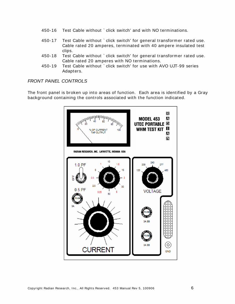
FRONT PANEL CONTROLS The front panel is broken up into areas of function. Each area is identified by a Gray background containing the controls associated with the function indicated.
Copyright Radian Research, Inc., All Rights Reserved. 453 Manual Rev 5, 100906 7
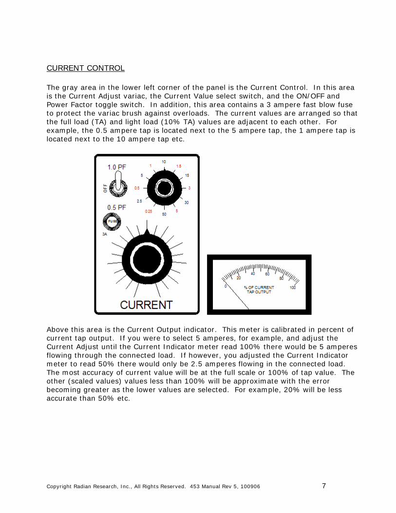
CURRENT CONTROL The gray area in the lower left corner of the panel is the Current Control. In this area is the Current Adjust variac, the Current Value select switch, and the ON/OFF and Power Factor toggle switch. In addition, this area contains a 3 ampere fast blow fuse to protect the variac brush against overloads. The current values are arranged so that the full load (TA) and light load (10% TA) values are adjacent to each other. For example, the 0.5 ampere tap is located next to the 5 ampere tap, the 1 ampere tap is located next to the 10 ampere tap etc.
Above this area is the Current Output indicator. This meter is calibrated in percent of current tap output. If you were to select 5 amperes, for example, and adjust the Current Adjust until the Current Indicator meter read 100% there would be 5 amperes flowing through the connected load. If however, you adjusted the Current Indicator meter to read 50% there would only be 2.5 amperes flowing in the connected load. The most accuracy of current value will be at the full scale or 100% of tap value. The other (scaled values) values less than 100% will be approximate with the error becoming greater as the lower values are selected. For example, 20% will be less accurate than 50% etc.
Copyright Radian Research, Inc., All Rights Reserved. 453 Manual Rev 5, 100906 8
WARNING
THE MODEL UTEC 453's CURRENT VALUE SELECT SWITCH SHOULD NEVER BE OPERATED WHILE THE CURRENT IS ADJUSTED UP AND THE ON/OFF TOGGLE SWITCH IS IN THE ‘ON’ POSITION. DOING SO WILL DECREASE THE LIFE OF THE SWITCH AND COULD CAUSE OTHER PERMANENT DAMAGE.
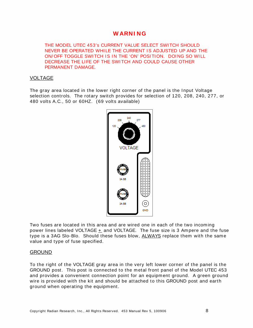
VOLTAGE The gray area located in the lower right corner of the panel is the Input Voltage selection controls. The rotary switch provides for selection of 120, 208, 240, 277, or 480 volts A.C., 50 or 60HZ. (69 volts available)
Two fuses are located in this area and are wired one in each of the two incoming power lines labeled VOLTAGE + and VOLTAGE. The fuse size is 3 Ampere and the fuse type is a 3AG Slo-Blo. Should these fuses blow, ALWAYS replace them with the same value and type of fuse specified.
GROUND To the right of the VOLTAGE gray area in the very left lower corner of the panel is the GROUND post. This post is connected to the metal front panel of the Model UTEC 453 and provides a convenient connection point for an equipment ground. A green ground wire is provided with the kit and should be attached to this GROUND post and earth ground when operating the equipment.
Copyright Radian Research, Inc., All Rights Reserved. 453 Manual Rev 5, 100906 9
UNDERSTANDING THE RADIAN RESEARCH, INC. TEST CABLE The Radian Research, Inc. Test Cables are different from other load box test cables that you may have used before in that there is one additional wire to connect, labeled with a Yellow marker that says ‘POTENTIAL RETURN'. This wire is necessary to maximize the accuracy of the test kit. In order to realize the most accurate test of a watthour meter, the Reference Standard potential must be connected directly across the potential coil of the meter under test (MUT). In most load boxes this is not the case as the Reference Standard potential coil is connected to the MUT through the two wires that power the load box, thereby introducing a voltage drop due to the current being drawn by the load box. All Radian Research, Inc. Test Cables are designed with separate conductors for the Reference Standard. These separate conductors are one of the wires in the VOLTAGE + and one of the wires in the POTENTIAL RETURN. The Radian Research, Inc. Model UTEC 453 is an ‘OPEN LINK' test kit and requires that the meter voltage clips be opened when testing the meter to isolate the voltage circuit from the current circuit. To test socket base self-contained, Forms 2, 12, 13, 14, 15, 16 and 17, a test adapter must be used so that the current circuits can be isolated from the customer's load and so the open end of the voltage coil can be accessed. Currently, there are two manufactures of test adapters for this purpose, Ekstrom and Megger (AVO/Multi-Amp). Connection charts are available from Radian Research, Inc. for the adapters listed below. These charts detail the connections necessary to perform Series and Element tests. In addition, the voltage connections are outlined with a column labeled ‘LAST JUMPER'. The ‘LAST JUMPER' is the final jumper to be installed in any adapter wiring situation. Insertion of this jumper puts voltage on the Model UTEC 453 and the watthour meter mounted in the Test Adapter.
EKSTROM `S' BASE TEST ADAPTERS MODEL FORMS TESTED LINE FUSE TJS-6022 1, 2, 3, 4, 12 250V TJS-6029 1, 2, 3, 4, 12 600V TJCT-6254 5, 6, 8, 9, 10 600V TJP-6500 14, 15, 16 600V TJP-6504 12, 14, 15, 16 600V
MULTI-AMP `S' BASE TEST ADAPTERS MODEL FORMS TESTED LINE FUSE 99801 1, 2, 3, 4, 12 250V 99805 1, 2, 3, 4, 12 600V 99802 14, 15, 16 250V 99806 14, 15, 16 600V 99803 6, 8, 9, 10 250V 99807 6, 8, 9, 10 600V 99804 5, 13 250V 99808 5, 13 600V UJT-99 All 600V

Copyright Radian Research, Inc., All Rights Reserved. 453 Manual Rev 5, 100906 10
Socket base transformer rated meters installed with test switches may be tested using the test cables terminated with clips. Meters without test switches require the use of a test adapter. The test kit obtains its operating voltage from the ‘A' phase service to the meter. Therefore, if a Form 14, 15, 16 or 17 meter is being tested, the ‘A' phase voltage clip is left closed (B and C voltage clips are opened). The remaining voltage coils are then connected to ‘A' phase with jumpers to put all voltage coils in parallel during testing. On all Radian Research, Inc. cables there are three voltage wires at the end of the test cable. One is labeled with a red marker `VOLTAGE +'. This wire is connected to the (+) or high side of the ‘A' phase (left stator) voltage to which the high side of ‘B' (rear stator) and ‘C' (right stator) phase voltage coils have been jumpered after the test clips have been opened.
WARNING
FAILURE TO OPEN THE VOLTAGE CLIPS ON ‘B’ AND ‘C’ PHASE BEFORE JUMPERING TO ‘A’ PHASE WILL CAUSE A PHASE-TO-PHASE SHORT. THIS WILL CAUSE PERMANENT DAMAGE TO THE TEST KIT AND CAN RESULT IN INJURY TO OPERATING PERSONNEL. IT IS RECOMMENDED THAT THE JUMPER CONNECTIONS BE MADE USING A FUSED JUMPER LEAD SUCH AS THE RADIAN RESEARCH, INC. MODEL UTEC 231 OR 234.
Another voltage wire is labeled with a black marker ‘VOLTAGE'. This wire is connected to the return or low side of ‘A' phase. The two leads ‘VOLTAGE+' and ‘VOLTAGE' provide the voltage to power the test kit. Consequently, the ‘A' phase voltage value should be selected on the test kit and Reference Standard. The last voltage wire is labeled with yellow marker `POTENTIAL RETURN'. This wire is connected to the end of the voltage coils that are isolated from their respective current circuits by open voltage clips. If the meter has more than one voltage return, such as Form 5, 6, 8, 10, 13 or 15, jumper the other returns to the `A' phase voltage coil return. In the case of transformer rated meters, the voltage coils of the meter are all isolated from the current circuits, therefore, no voltage test clips are provided by their manufacturer. In this case, the `VOLTAGE' wire (black) and the `POTENTIAL RETURN' wire (yellow) are both connected to the voltage coil return. The `B' and `C' phase voltages must be isolated from their respective voltage sources by opening the test switch or using an adapter BEFORE they are jumpered in parallel to the `A' phase voltage source.
Copyright Radian Research, Inc., All Rights Reserved. 453 Manual Rev 5, 100906 11
WARNING
FAILURE TO OPEN THE VOLTAGE CLIPS ON ‘B’ AND ‘C’ PHASE BEFORE JUMPERING TO ‘A’ PHASE WILL CAUSE A PHASE-TO-PHASE SHORT. THIS WILL CAUSE PERMANENT DAMAGE TO THE TEST KIT AND CAN RESULT IN INJURY TO OPERATING PERSONNEL. IT IS RECOMMENDED THAT THE JUMPER CONNECTIONS BE MADE USING A FUSED JUMPER LEAD SUCH AS THE RADIAN RESEARCH, INC. MODEL UTEC 231 OR 234.
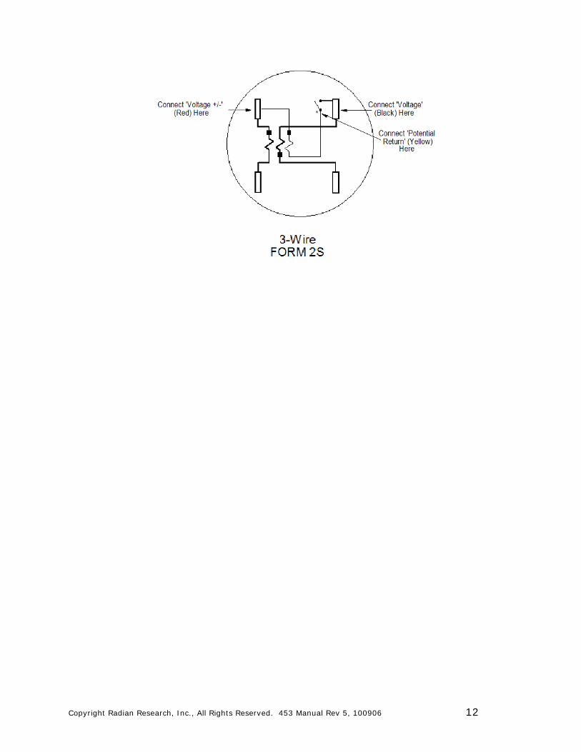
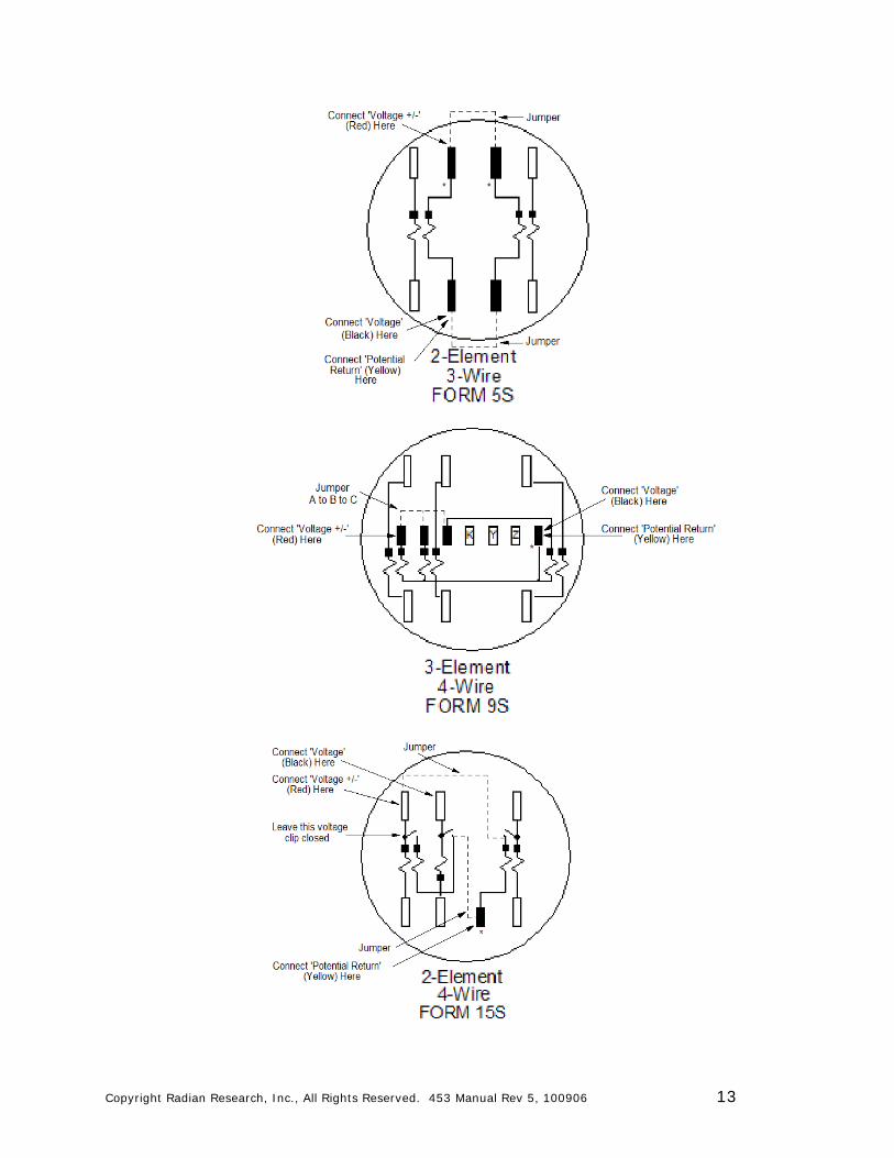
TEST CONNECTIONS The Test Cables for the Model UTEC 453 Portable WHM Test Kit are marked with color coded label bands near the connection end of the lead. Both the current and voltage leads have a + marked band. This + lead is the high polarity side of the current or voltage circuit. The return lead for both current and voltage has no polarity mark. The + (marked CURRENT +) of the current lead is connected to the high polarity of the ‘A' phase current element of the Meter Under Test (MUT), as shown in the diagrams below, and is indicated by a ‘+'. For series tests, the return of the ‘A' phase current element is jumpered to the high polarity of the next element. The return of that element is jumpered to the high polarity of the last current element and the return of the last current element is connected to the Test Cable current return lead (marked CURRENT). Thus, all the current elements of the MUT are connected in series aiding. For individual element test, the Test Cable current leads are connected across the current element of interest. The voltage + (red band marked VOLTAGE +) is connected to the high polarity of ‘A' phase voltage. The high polarity of the potential element is shown as ‘' in the diagrams below. The voltage return lead (black band marked VOLTAGE) is connected to the return side of the ‘A' phase voltage. If the MUT is a polyphase meter, the remaining potential elements (B, C) are isolated from their respective current circuits by opening the voltage clip or test switch and are connected in parallel with the ‘A' phase potential element. The remaining voltage test lead (yellow band marked POTENTIAL RETURN) is connected to the open voltage clip of the MUT. This connection is shown on the diagrams below by a ‘*'. Shown below are examples of connecting the voltage wires of the Test Cable to meter Forms 2, 5, 9 and 15. Other forms are connected in a similar manner. Refer to the ‘Connection Chart' section of this manual for meter base wiring and polarities of other form numbers.
Copyright Radian Research, Inc., All Rights Reserved. 453 Manual Rev 5, 100906 12
Copyright Radian Research, Inc., All Rights Reserved. 453 Manual Rev 5, 100906 13

Copyright Radian Research, Inc., All Rights Reserved. 453 Manual Rev 5, 100906 14
TEST PROCEDURE The test procedures outlined below are the recommended procedures for operating the Model UTEC 453. If your company does not have an established test procedure, it is recommended that you follow these procedures. If your company does have an established test procedure, follow your company's procedure modifying it to allow for the use of the ‘POTENTIAL RETURN' test cable wire. ALWAYS FOLLOW YOUR COMPANY'S SAFETY PROCEDURES WHEN USING RADIAN RESEARCH, INC. EQUIPMENT. IF THERE ARE DISAGREEMENTS BETWEEN SAFETY PROCEDURES IN THIS MANUAL AND THE ONES ESTABLISHED BY YOUR COMPANY, CHECK WITH YOUR COMPANY'S SAFETY MANAGER BEFORE USING ANY RADIAN RESEARCH, INC. PROCEDURE. Protective clothing such as long sleeve shirt and long pants made from a fire retardant material, safety glasses, hard hat, and 600V gloves should be worn when testing in the field using a live distribution service as a voltage source. Testing in the rain or in a flooded area should be avoided.
TESTING SELF-CONTAINED SOCKET BASE WATTHOUR METERS. (Forms 1, 2, 12, 13, 14, 15 and 16) Self-contained socket base meters must be tested with the aid of a test adapter. The test adapters available for this purpose are discussed on page 5-1. These adapters are designed to bypass the customer's load while the test is in progress by providing 300 ampere shorting bars in each of the phase currents provided by the adapter. The ‘A' phase voltage is usually made available on the front part of the adapter through a fuse which would isolate the test kit and meter from the service should a fault occur on the test side of the adapter. Adapters are available with 250V and 600V fuses. Be sure to select the fuse size to match your testing requirement. If tests are to be made at voltages above 240V, the 600V fuse type of adapter must be used to provide complete safe operation Procedure
1. Protective clothing such as long sleeve shirt and long pants made from a fire retardant material, safety glasses, hard hat, and 600V gloves should be worn when testing in the field using a live distribution service as a voltage source.
2. Remove the meter to be tested from the service box using your company's meter removal procedure.
3. Insert a test adapter, selected for the correct fuse voltage size and the form number of the meter to be tested.
4. Select the following switch positions on the Model UTEC 453. a) Current Power Factor Switch - set to OFF position b) Voltage Switch - set to the service voltage c) Position the Current Adjust knob to the far left rotation - full
counterclockwise (CCW)
Copyright Radian Research, Inc., All Rights Reserved. 453 Manual Rev 5, 100906 15
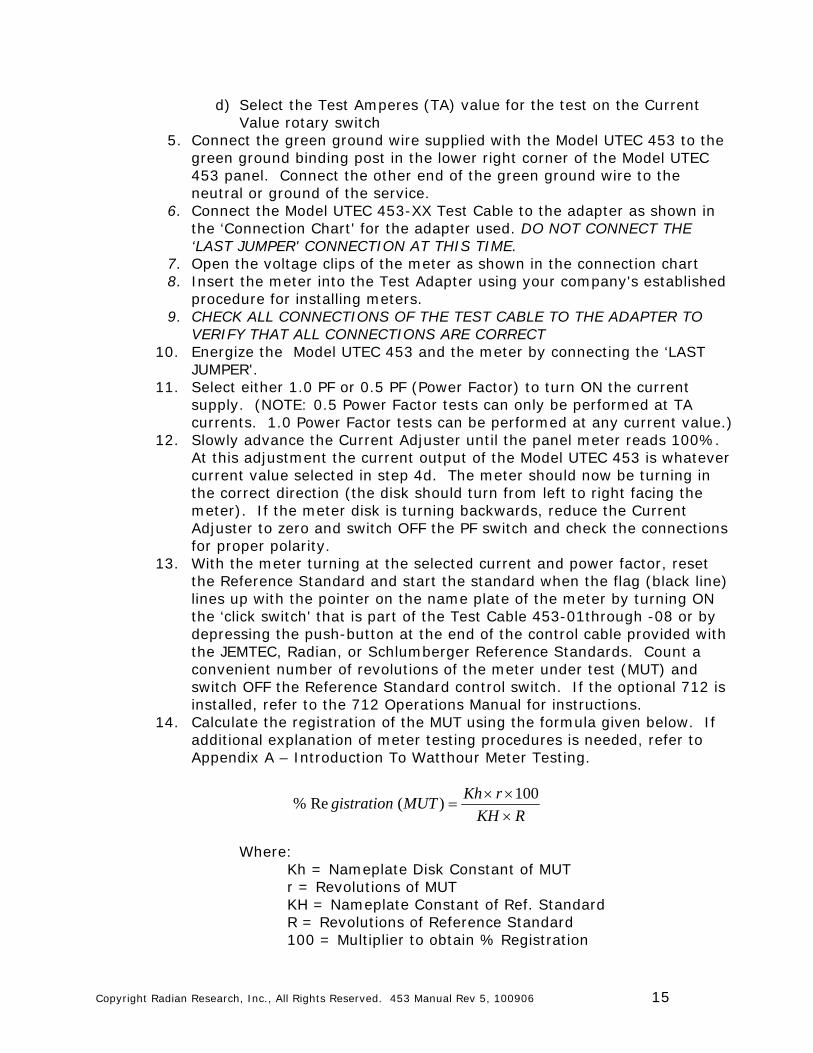
d) Select the Test Amperes (TA) value for the test on the Current Value rotary switch
5. Connect the green ground wire supplied with the Model UTEC 453 to the green ground binding post in the lower right corner of the Model UTEC 453 panel. Connect the other end of the green ground wire to the neutral or ground of the service.
6. Connect the Model UTEC 453-XX Test Cable to the adapter as shown in the ‘Connection Chart' for the adapter used. DO NOT CONNECT THE ‘LAST JUMPER' CONNECTION AT THIS TIME.
7. Open the voltage clips of the meter as shown in the connection chart 8. Insert the meter into the Test Adapter using your company's established
procedure for installing meters. 9. CHECK ALL CONNECTIONS OF THE TEST CABLE TO THE ADAPTER TO
VERIFY THAT ALL CONNECTIONS ARE CORRECT 10. Energize the Model UTEC 453 and the meter by connecting the ‘LAST
JUMPER'. 11. Select either 1.0 PF or 0.5 PF (Power Factor) to turn ON the current
supply. (NOTE: 0.5 Power Factor tests can only be performed at TA currents. 1.0 Power Factor tests can be performed at any current value.)
12. Slowly advance the Current Adjuster until the panel meter reads 100%. At this adjustment the current output of the Model UTEC 453 is whatever current value selected in step 4d. The meter should now be turning in the correct direction (the disk should turn from left to right facing the meter). If the meter disk is turning backwards, reduce the Current Adjuster to zero and switch OFF the PF switch and check the connections for proper polarity.
13. With the meter turning at the selected current and power factor, reset the Reference Standard and start the standard when the flag (black line) lines up with the pointer on the name plate of the meter by turning ON the ‘click switch' that is part of the Test Cable 453-01through -08 or by depressing the push-button at the end of the control cable provided with the JEMTEC, Radian, or Schlumberger Reference Standards. Count a convenient number of revolutions of the meter under test (MUT) and switch OFF the Reference Standard control switch. If the optional 712 is installed, refer to the 712 Operations Manual for instructions.
14. Calculate the registration of the MUT using the formula given below. If additional explanation of meter testing procedures is needed, refer to Appendix A – Introduction To Watthour Meter Testing.
RKH
rKhMUTgistration
100
)(Re%
Where: Kh = Nameplate Disk Constant of MUT
r = Revolutions of MUT KH = Nameplate Constant of Ref. Standard R = Revolutions of Reference Standard 100 = Multiplier to obtain % Registration
Copyright Radian Research, Inc., All Rights Reserved. 453 Manual Rev 5, 100906 16
15. When the test is complete, reduce the test current to zero (full CCW) and
switch OFF the power factor switch. Select the next load to be tested and repeat steps 9 – 14. If a new current value is desired, position the current value select switch to the new value before switching ON the current source.
WARNING
DO NOT SELECT A NEW CURRENT VALUE WHEN THE CURRENT IS ‘ON' AND ADJUSTED UP. DOING SO WILL CAUSE PERMANENT DAMAGE TO THE SWITCHES OF THE MODEL UTEC 453 REDUCING THEIR EXPECTED LIFE! ALWAYS TURN THE CURRENT ADJUST FULL DOWN (CCW) AND SWITCH ‘OFF' THE PF SWITCH BEFORE OPERATING THE CURRENT VALUE SWITCH.
16. When all tests are complete, turn OFF the PF switch. Remove the ‘LAST
JUMPER' first to de-energize the Model UTEC 453 and MUT. Remove the meter from the test adapter following your company's established procedure for removing meters.
17. Remove the Test Cable from the test adapter, and remove the test adapter from the service following your company's established safety procedures.
18. CLOSE THE VOLTAGE CLIP ON THE METER and reinstall the meter in the service following your company's established procedure for installing meters.
19. The Test Cable should be coiled on top of the load panel for storage, being careful to position the cable terminations so they will not damage the Reference Standard or Model UTEC 453 panels.
TESTING TRANSFORMER RATED SOCKET BASE WATTHOUR METERS. (FORMS 3, 4, 5, 6, 8, 9 AND 10) Transformer rated socket base watthour meters are most commonly installed using a test switch or test block. If a test switch or test block is included in the service to be tested a test adapter is not necessary. The Test Cable of the Model UTEC 453 can be connected directly to the test switch or test block. If, however, there is no test switch or test block, a test adapter will be required and the procedure for ‘Testing Self-Contained Socket Base Watthour Meters' should be followed.
WARNING
WHEN TESTING A TRANSFORMER SOCKET BASE METER WITH A TEST ADAPTER, BE CERTAIN TO SHORT THE SECONDARY TERMINALS OF
Copyright Radian Research, Inc., All Rights Reserved. 453 Manual Rev 5, 100906 17
THE CURRENT TRANSFORMERS BEFORE REMOVING THE METER FROM THE SOCKET. FAILURE TO DO THIS COULD CAUSE SERIOUS HARM TO OPERATING PERSONNEL DUE TO THE EXTREME HIGH VOLTAGES GENERATED BY OPEN CURRENT TRANSFORMER SECONDARIES. FOLLOW YOUR COMPANY'S ESTABLISHED PROCEDURE FOR REMOVING TRANSFORMER RATED METERS FROM SERVICE TO PREVENT THIS POTENTIALLY DANGEROUS SITUATION!
If the service installation to be tested contains a test switch or test block use the following procedure. It is recommended that Test Cables 453-05, 453-07, 453-15 or 453-17 be used to perform this test procedure. If the Model UTEC 453 was purchased with 453-02, 453-03, 453-04, 453-12, 453-13 or 453-14 cables, call Radian Research, Inc. for information on cable adapter kits to convert these cables with test adapter terminations to test clips or super hooks; or purchase the correct Test Cable for your application. Procedure
1. Protective clothing such as long sleeve shirt and long pants made from a fire retardant material, safety glasses, hard hat, and 600V gloves should be worn when testing in the field using a live distribution service as a voltage source.
2. Open all knife switches on the test switch to totally isolate the watthour meter from the service. If there is a knife switch located in the neutral (ground) connection, this switch should be left in the closed position.
3. Select the following switch positions on the Model UTEC 453. a. Current Power Factor Switch - set to OFF position b. Voltage Switch - set to the correct service voltage c. Position the Current Adjust knob to the far left rotation - full
counter clock wise (CCW) d. Select the Test Amperes (TA) value for the test on the Current
Value rotary switch 4. Connect the green ground wire supplied with the Model UTEC 453 to the
green ground binding post in the lower right corner of the Model UTEC 453 panel. Connect the other end of the green ground wire to the neutral or ground of the service.
5. Connect the Model UTEC 453-XX Test Cable to the test switch as follows.
WARNING
MAKE ALL TEST CABLE CONNECTIONS TO THE METER SIDE OF THE TEST SWITCH OR TEST BLOCK! CONNECTION OF ANY TEST CABLE LEADS TO THE SERVICE SIDE OF THE TEST SWITCH OR TEST BLOCK WILL CAUSE
Copyright Radian Research, Inc., All Rights Reserved. 453 Manual Rev 5, 100906 18
PERMANENT DAMAGE TO THE MODEL UTEC 453 TEST KIT AND MAY RESULT IN INJURY TO OPERATING PERSONNEL!
a. Connect the red terminated Test Cable lead marked
‘CURRENT+' to the ‘A' Phase current switch high polarity. Current polarities are shown in the connection charts.
b. Connect series jumper wires (not provided with Test Cable or Model UTEC 453) from the return of ‘A' Phase current to the high polarity of the next current phase. Continue to connect current elements in series aiding until all current elements are connected. (NOTE: This procedure is for performing series tests.
c. Connect the black terminated Test Cable lead marked ‘CURRENT' to the return of the last current element in the series connection.
d. Connect the red terminated Test Cable lead marked ‘VOLTAGE +' (Red marker) to the high polarity of the ‘A' Phase voltage. (Refer to ‘Connection Chart' for potential element polarities.)
e. Connect the high polarity of the remaining phases (B,C) to ‘A' Phase high polarity using fused jumpers, (not supplied with Test Cable or Model UTEC 453).
WARNING
FAILURE TO OPEN THE VOLTAGE SWITCHES ON ‘B' AND ‘C' PHASE BEFORE JUMPERING TO ‘A' PHASE WILL CAUSE A PHASE-TO-PHASE SHORT. THIS WILL CAUSE PERMANENT DAMAGE TO THE TEST KIT AND CAN RESULT IN INJURY TO OPERATING PERSONNEL. IT IS RECOMMENDED THAT THE JUMPER CONNECTIONS BE MADE USING A FUSED JUMPER LEAD SUCH AS THE RADIAN RESEARCH, INC. MODEL UTEC 231 OR 234.
6. Connect the black terminated Test Cable lead marked ‘VOLTAGE' (Black
marker) to the voltage return for ‘A' Phase. 7. Connect the voltage returns of the remaining phase voltages (B,C) to the
voltage return of ‘A' Phase using fused jumpers. 8. Connect the black terminated Test Cable lead marked ‘POTENTIAL
RETURN' to the voltage return connection of all voltage phases made in step 7.
9. CHECK ALL CONNECTIONS OF THE TEST CABLE TO THE TEST SWITCH TO VERIFY THAT ALL CONNECTIONS ARE CORRECT.
10. Energize the Model UTEC 453 and the meter by closing the ‘A' Phase voltage knife switch. DO NOT CLOSE B OR C PHASE VOLTAGE KNIFE SWITCHES! THIS WILL CAUSE A PHASE-TO-PHASE SHORT AND MAY CAUSE PERMANENT DAMAGE TO THE MODEL UTEC 453 AND INJURY TO OPERATING PERSONNEL.
Copyright Radian Research, Inc., All Rights Reserved. 453 Manual Rev 5, 100906 19
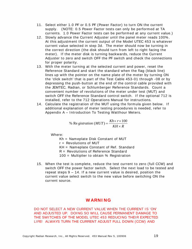
11. Select either 1.0 PF or 0.5 PF (Power Factor) to turn ON the current supply. (NOTE: 0.5 Power Factor tests can only be performed at TA currents. 1.0 Power Factor tests can be performed at any current value.)
12. Slowly advance the Current Adjuster until the panel meter reads 100%. At this adjustment the current output of the Model UTEC 453 is whatever current value selected in step 3d. The meter should now be turning in the correct direction (the disk should turn from left to right facing the meter). If the meter disk is turning backwards, reduce the Current Adjuster to zero and switch OFF the PF switch and check the connections for proper polarity.
13. With the meter turning at the selected current and power, reset the Reference Standard and start the standard when the flag (black line) lines up with the pointer on the name plate of the meter by turning ON the ‘click switch' that is part of the Test Cable 453-01 through -08 or by depressing the push-button at the end of the control cable provided with the JEMTEC, Radian, or Schlumberger Reference Standards. Count a convenient number of revolutions of the meter under test (MUT) and switch OFF the Reference Standard control switch. If the optional 712 is installed, refer to the 712 Operations Manual for instructions.
14. Calculate the registration of the MUT using the formula given below. If additional explanation of meter testing procedures is needed, refer to Appendix A – Introduction To Testing Watthour Meters.
RKH
rKhMUTgistration
100
)(Re%
Where: Kh = Nameplate Disk Constant of MUT r = Revolutions of MUT KH = Nameplate Constant of Ref. Standard R = Revolutions of Reference Standard 100 = Multiplier to obtain % Registration
15. When the test is complete, reduce the test current to zero (full CCW) and
switch OFF the power factor switch. Select the next load to be tested and repeat steps 9 – 14. If a new current value is desired, position the current value select switch to the new value before switching ON the current source.
WARNING
DO NOT SELECT A NEW CURRENT VALUE WHEN THE CURRENT IS ‘ON' AND ADJUSTED UP. DOING SO WILL CAUSE PERMANENT DAMAGE TO THE SWITCHES OF THE MODEL UTEC 453 REDUCING THEIR EXPECTED LIFE! ALWAYS TURN THE CURRENT ADJUST FULL DOWN (CCW) AND
Copyright Radian Research, Inc., All Rights Reserved. 453 Manual Rev 5, 100906 20
SWITCH ‘OFF' THE PF SWITCH BEFORE OPERATING THE CURRENT VALUE SWITCH.
16. When all tests are complete, turn OFF the PF switch. Open the ‘A' Phase
voltage switch to de-energize the Model UTEC 453 and MUT. 17. Remove the Test Cable from the test switch, and remove all jumpers
used for testing. 18. RESTORE ALL TEST SWITCH KNIFE SWITCHES TO THE CLOSED
POSITION FOLLOWING YOUR COMPANY'S ESTABLISHED PROCEDURE. 19. REMOVE ANY SHORTS PLACED ACROSS CURRENT TRANSFORMERS
SECONDARIES DURING TESTING 20. The Test Cable should be coiled on top of the load panel for storage,
being careful to position the cable terminations so they will not damage the Reference Standard or Model UTEC 453 panels.
TESTING BOTTOM CONNECTED WATTHOUR METERS Bottom connected watthour meters are tested in the same way as socket base transformer watthour meters. Most transformer rated bottom connected meters are installed using test switches or test blocks. If the watthour meter to be tested is installed with a test switch or test block, follow the procedure for ‘TESTING TRANSFORMER RATED SOCKET BASE WATTHOUR METERS'. If the meter to be tested has no test switch or test block, it is recommended that the meter be removed to the meter shop for testing.
TESTING WATTHOUR METERS IN THE FIELD USING A PHOTO PICK-UP The speed with which a test can be performed and the accuracy of the test can be greatly improved by using the Radian RM-110 Comparator. The RM-110 Comparator uses electronic sensors to detect disk edge, infra-red, and electronic pulses to control the meter test. These sensors are available in a variety of mounting methods. The RM-110 Comparator will count the pulses from the Reference Standard in the Model UTEC 453 Test Kit. With this control, tests can be reduced to one revolution instead of the normal 10 revolutions associated with ‘click switch' methods. Accuracy is greatly enhanced since the human reaction time is removed from the error trail. In addition, solid state meters with infrared emitters and KYZ pulses can control the test. The Model UTEC 711 with the optional 711-01 relay is required for use with switched potential Reference Standards such as the Scientific Columbus SC-10. The RM-110 is an optional accessory for the Model UTEC 453. Call the Radian Research, Inc. Sales office for more information at 765-449-5500.
CALCULATION OF TEST ACCURACY WHEN USING REFERENCE STANDARDS THAT READ IN WATTHOURS When using a reference standard like the JEMTEC SC-30 or Radian RM-10, use the following formula for calculation of the registration of the meter under test (MUT)
Copyright Radian Research, Inc., All Rights Reserved. 453 Manual Rev 5, 100906 21
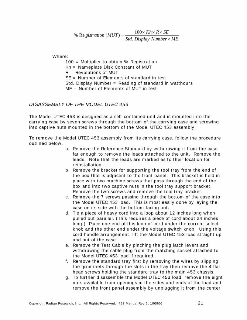
MENumberDisplayStd
SERKhMUTgistration
.
100)(Re%
Where:
100 = Multiplier to obtain % Registration Kh = Nameplate Disk Constant of MUT R = Revolutions of MUT SE = Number of Elements of standard in test Std. Display Number = Reading of standard in watthours ME = Number of Elements of MUT in test
DISASSEMBLY OF THE MODEL UTEC 453 The Model UTEC 453 is designed as a self-contained unit and is mounted into the carrying case by seven screws through the bottom of the carrying case and screwing into captive nuts mounted in the bottom of the Model UTEC 453 assembly. To remove the Model UTEC 453 assembly from its carrying case, follow the procedure outlined below.
a. Remove the Reference Standard by withdrawing it from the case far enough to remove the leads attached to the unit. Remove the leads. Note that the leads are marked as to their location for reinstallation.
b. Remove the bracket for supporting the tool tray from the end of the box that is adjacent to the front panel. This bracket is held in place with two machine screws that pass through the end of the box and into two captive nuts in the tool tray support bracket. Remove the two screws and remove the tool tray bracket.
c. Remove the 7 screws passing through the bottom of the case into the Model UTEC 453 load. This is most easily done by laying the case on its side with the bottom facing out.
d. Tie a piece of heavy cord into a loop about 12 inches long when pulled out parallel. (This requires a piece of cord about 24 inches long.) Place one end of this loop of cord under the current select knob and the other end under the voltage switch knob. Using this cord handle arrangement, lift the Model UTEC 453 load straight up and out of the case.
e. Remove the Test Cable by pinching the plug latch levers and withdrawing the cable plug from the matching socket attached to the Model UTEC 453 load if required.
f. Remove the standard tray first by removing the wires by slipping the grommets through the slots in the tray then remove the 4 flat head screws holding the standard tray to the main 453 chassis.
g. To further disassemble the Model UTEC 453 load, remove the eight nuts available from openings in the sides and ends of the load and remove the front panel assembly by unplugging it from the center
Copyright Radian Research, Inc., All Rights Reserved. 453 Manual Rev 5, 100906 22
panel assembly as required. Some of the heavy 8AWG wiring must be removed by removal of the nuts etc., holding these wires onto the various components.
h. Once the front panel assembly is removed, the center panel can be removed by taking out the six flathead screws passing through the sides of the chassis and fastening into captive nuts assembled to the center panel. The plugs mounted to the center panel can be removed by pushing them all the way to one side and cocking the plug while pushing it toward the bottom of the load.
To reassemble, reverse the procedure outlined above being careful not to pinch any of the wires when reassembling the
SERVICE The Model UTEC 453 is designed with plug together modules or assemblies. Radian Research, Inc. maintains a stock of these assemblies and, in emergency situations, can usually supply a replacement module or assembly over-night if requested before 12:00 noon. The normal response time is 4 to 5 working days.
WARRANTY SERVICE WARNING! REMOVING THE WARRANTY SEAL WITHOUT FIRST OBTAINING PERMISSION FROM THE FACTORY WILL VOID THE WARRANTY. The Model UTEC 453 has a two year warranty. See Warranty Statement. All warranty replacements must be authorized by the factory and all warranty returns require an "RA" number (Return Authorization number). A separate number is required for each warranty claim. Items being returned for warranty repair MUST be shipped prepaid. Radian Research, Inc. will accept no C.O.D. or COLLECT shipments. Shipments must be made in the original packing so that no damage will occur in transit. Items should be shipped fully insured as Radian Research, Inc. does not accept any liability for damage caused by improper packing or handling during shipment. Radian Research, Inc. will prepay the regular shipping expenses of warranty repairs being returned after repair. Overnight or Express shipping service costs will not be paid by Radian Research, Inc. RULES FOR WARRANTY REPAIR
1. Call factory for RA #. This number must appear on the equipment and all paperwork.
2. Ship unit in original packing, PREPAID, to Radian Research, Inc.
AFTER WARRANTY SERVICE After Warranty Service is basically the same as Warranty Service except that a Purchase Order is required to perform the service and the user pays the shipping costs
Copyright Radian Research, Inc., All Rights Reserved. 453 Manual Rev 5, 100906 23
both ways. Estimates of repair cost can be given if requested, however, if the repair is not made, the cost of labor to obtain the estimate will be invoiced at the then hourly repair rate. RULES FOR AFTER WARRANTY SERVICE
1. Call factory for RA #. This number must appear on the equipment and all paperwork.
2. Issue a Purchase Order for Repair. 3. Ship unit in original packing, PREPAID, to Radian Research, Inc.
Copyright Radian Research, Inc., All Rights Reserved. 453 Manual Rev 5, 100906 24
LIMITED PRODUCT WARRANTY
Radian Research warrants to the original purchaser that it will correct all defects in material and/or workmanship in the instrument, test equipment or software covered by this Warranty (herein called "Product"), provided that Radian Research is notified of such defect within the Warranty Period (set forth below) in accordance with paragraph four of this Warranty. The Warranty Period shall begin on the date of shipment of the Product or the date of the issuance of this Warranty certificate, whichever is later. If no Warranty Period is specified below and signed by an authorized representative of Radian Research, the Warranty Period shall be two (2) years. In no event shall this Warranty remain in effect for more than the stated Warranty Period plus two (2) months after the date of shipment. Radian Research's sole obligation and the purchaser's sole remedy under this Warranty is limited to repair or replacement, at Radian Research's option, free of charge, F.O.B. Radian Research's factory at Lafayette, Indiana of any workmanship and/or part which in Radian Research's sole judgment shows evidence of defect. On-site Warranty repairs will be made when in Radian Research's judgment the Product cannot practically be shipped to Radian Research's factory. Any modifications, additions or upgrades made to the Product or control software after this Warranty becomes effective shall not extend the term of this Warranty. The Warranty set forth above shall be applicable only if the Product: 1. Is used for the specific purpose for which it was intended; 2. Is operated in accordance with instructions, if any, supplied by Radian Research; 3. Has not been modified, neglected, altered, tampered with, vandalized, abused or misused, or subjected to accident, fire, flood or other casualty; 4. Has not been repaired by unauthorized persons; 5. Has not had its serial number altered, defaced or removed; 6. Has not been connected, installed or adjusted other than in accordance with the instructions, if any, furnished by Radian Research. The Warranty set forth herein does not apply to defects resulting from ordinary wear, tear and usage, or any cause, similar or dissimilar, not resulting solely from defective material and/or workmanship. The Warranty set forth herein shall not be effective unless: 1. Notice of defect is given to Radian Research by phone, fax, or mail as soon as the defect is discovered. 2. Notice of defect contains the following information: Product serial number, Product model number, date of original installation, and an accurate and complete description of the defect including the exact circumstances leading to the defect. 3. The defective Product or part is returned only upon authorization from Radian Research, as evidenced by the issuing of a Return Authorization number, and that the transportation charges are prepaid (except that Radian Research may, at its option, appoint a qualified representative to make field inspections of the Product for which purpose the purchaser shall permit such representative to enter upon its premises and examine the Product). 4. The Return Authorization number is written on the shipping label and all paperwork accompanying defective Product or part. 5. The defective product or part is returned in the original packing or packing approved by Radian Research. Radian Research is not responsible for drayage charges, damages or labor costs incurred in conjunction with failure, removal or reinstallation of any Product, all of which shall be at the purchaser's expense. Radian Research is not responsible for special, incidental or consequential damages, whether resulting from breach of warranty, negligence or any other reason. Radian Research manufactured parts will be available for a minimum period of one (1) year after the manufacture of the Product has been discontinued. Radian Research will provide original purchaser during the Warranty Period, unlimited telephone consulting time for the purpose of product trouble shooting/servicing and for the first thirty (30) days of the Warranty Period, unlimited telephone consulting time for the purpose of product/software application. THE WARRANTY CONTAINED HEREIN IS IN LIEU OF ALL OTHER WARRANTIES AND Radian Research MAKES NO OTHER WARRANTIES, EXPRESS OR IMPLIED, INCLUDING, BUT NOT LIMITED TO, WARRANTIES OR CONDITION, DESIGN, MERCHANTABILITY, FITNESS FOR A PARTICULAR PURPOSE, OR ANY OTHER MATTER. No other Warranty, express or implied, is authorized by Radian Research, and no representative of Radian Research or any other person has any authority to amend, extend, modify, enlarge or otherwise alter the foregoing Warranty and disclaimers in any way whatsoever, except as provided for in an Extended Limited Product Warranty Agreement. 030906
Copyright Radian Research, Inc., All Rights Reserved. 453 Manual Rev 5, 100906 25
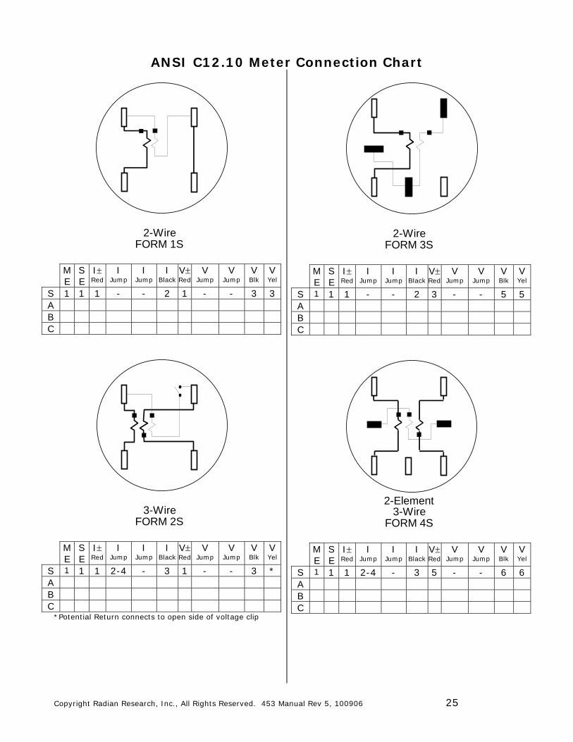
ANSI C12.10 Meter Connection Chart
2-WireFORM 1S
M E
S E
I Red
I Jump
I Jump
I Black
V Red
V Jump
V Jump
V Blk
V Yel
S 1 1 1 - - 2 1 - - 3 3 A B C
3-WireFORM 2S
M E
S E
I Red
I Jump
I Jump
I Black
V Red
V Jump
V Jump
V Blk
V Yel
S 1 1 1 2-4 - 3 1 - - 3 * A B C
*Potential Return connects to open side of voltage clip
2-WireFORM 3S
M E
S E
I Red
I Jump
I Jump
I Black
V Red
V Jump
V Jump
V Blk
V Yel
S 1 1 1 - - 2 3 - - 5 5 A B C
2-Element3-Wire
FORM 4S
M E
S E
I Red
I Jump
I Jump
I Black
V Red
V Jump
V Jump
V Blk
V Yel
S 1 1 1 2-4 - 3 5 - - 6 6 A B C
Copyright Radian Research, Inc., All Rights Reserved. 453 Manual Rev 5, 100906 26
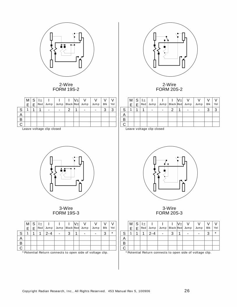
2-WireFORM 19S-2
M E
S E
I Red
I Jump
I Jump
I Black
V Red
V Jump
V Jump
V Blk
V Yel
S 1 1 1 - - 2 1 - - 3 3 A B C
Leave voltage clip closed
3-WireFORM 19S-3
M E
S E
I Red
I Jump
I Jump
I Black
V Red
V Jump
V Jump
V Blk
V Yel
S 1 1 1 2-4 - 3 1 - - 3 * A B C
*Potential Return connects to open side of voltage clip.
2-WireFORM 20S-2
M E
S E
I Red
I Jump
I Jump
I Black
V Red
V Jump
V Jump
V Blk
V Yel
S 1 1 1 - - 2 1 - - 3 3 A B C
Leave voltage clip closed
3-WireFORM 20S-3
M E
S E
I Red
I Jump
I Jump
I Black
V Red
V Jump
V Jump
V Blk
V Yel
S 1 1 1 2-4 - 3 1 - - 3 * A B C
*Potential Return connects to open side of voltage clip.
Copyright Radian Research, Inc., All Rights Reserved. 453 Manual Rev 5, 100906 27
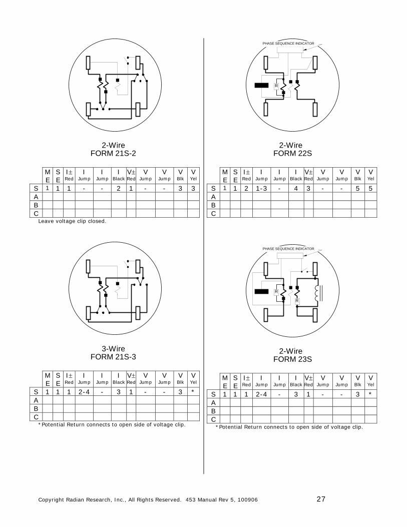
2-WireFORM 21S-2
M E
S E
I Red
I Jump
I Jump
I Black
V Red
V Jump
V Jump
V Blk
V Yel
S 1 1 1 - - 2 1 - - 3 3 A B C
Leave voltage clip closed.
3-WireFORM 21S-3
M E
S E
I Red
I Jump
I Jump
I Black
V Red
V Jump
V Jump
V Blk
V Yel
S 1 1 1 2-4 - 3 1 - - 3 * A B C
*Potential Return connects to open side of voltage clip.
2-WireFORM 22S
R
PHASE SEQUENCE INDICATOR
M E
S E
I Red
I Jump
I Jump
I Black
V Red
V Jump
V Jump
V Blk
V Yel
S 1 1 2 1-3 - 4 3 - - 5 5 A B C
2-WireFORM 23S
R
R
PHASE SEQUENCE INDICATOR
M E
S E
I Red
I Jump
I Jump
I Black
V Red
V Jump
V Jump
V Blk
V Yel
S 1 1 1 2-4 - 3 1 - - 3 * A B C
*Potential Return connects to open side of voltage clip.
Copyright Radian Research, Inc., All Rights Reserved. 453 Manual Rev 5, 100906 28
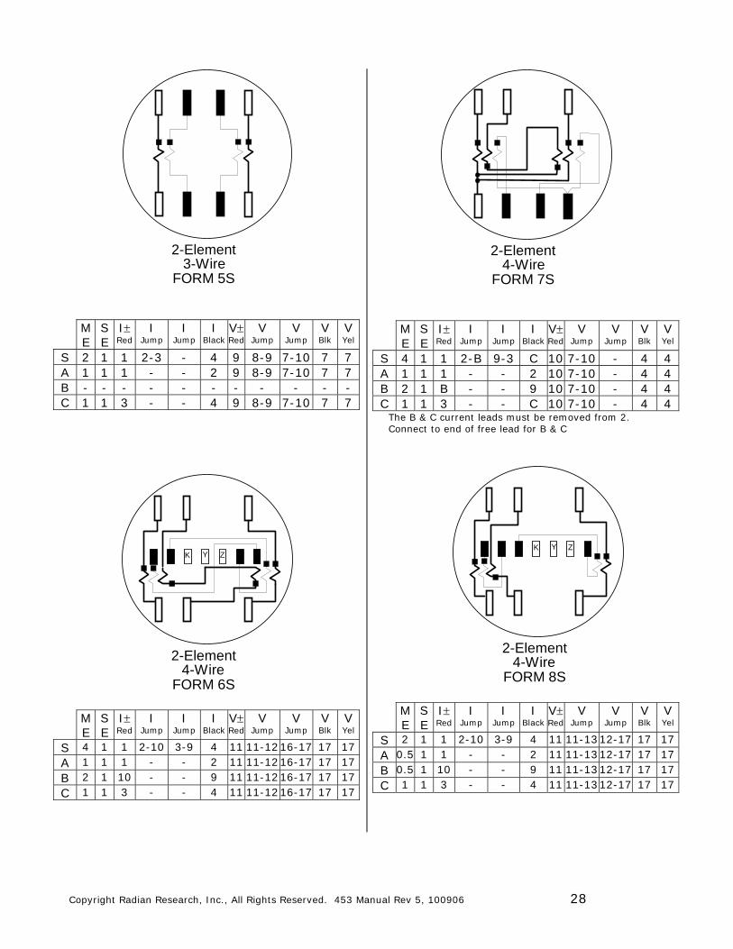
2-Element3-Wire
FORM 5S
M E
S E
I Red
I Jump
I Jump
I Black
V Red
V Jump
V Jump
V Blk
V Yel
S 2 1 1 2-3 - 4 9 8-9 7-10 7 7 A 1 1 1 - - 2 9 8-9 7-10 7 7 B - - - - - - - - - - - C 1 1 3 - - 4 9 8-9 7-10 7 7
2-Element4-Wire
FORM 6S
YK Z
M E
S E
I Red
I Jump
I Jump
I Black
V Red
V Jump
V Jump
V Blk
V Yel
S 4 1 1 2-10 3-9 4 11 11-12 16-17 17 17 A 1 1 1 - - 2 11 11-12 16-17 17 17 B 2 1 10 - - 9 11 11-12 16-17 17 17 C 1 1 3 - - 4 11 11-12 16-17 17 17
2-Element4-Wire
FORM 7S
M E
S E
I Red
I Jump
I Jump
I Black
V Red
V Jump
V Jump
V Blk
V Yel
S 4 1 1 2-B 9-3 C 10 7-10 - 4 4 A 1 1 1 - - 2 10 7-10 - 4 4 B 2 1 B - - 9 10 7-10 - 4 4 C 1 1 3 - - C 10 7-10 - 4 4
The B & C current leads must be removed from 2. Connect to end of free lead for B & C
2-Element4-Wire
FORM 8S
YK Z
M E
S E
I Red
I Jump
I Jump
I Black
V Red
V Jump
V Jump
V Blk
V Yel
S 2 1 1 2-10 3-9 4 11 11-13 12-17 17 17 A 0.5 1 1 - - 2 11 11-13 12-17 17 17 B 0.5 1 10 - - 9 11 11-13 12-17 17 17 C 1 1 3 - - 4 11 11-13 12-17 17 17
Copyright Radian Research, Inc., All Rights Reserved. 453 Manual Rev 5, 100906 29
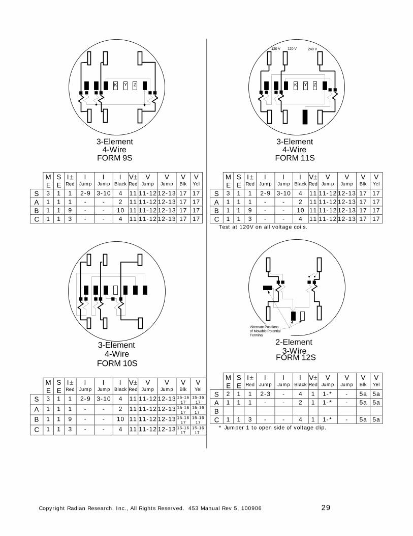
3-Element4-Wire
FORM 9S
YK Z
M E
S E
I Red
I Jump
I Jump
I Black
V Red
V Jump
V Jump
V Blk
V Yel
S 3 1 1 2-9 3-10 4 11 11-12 12-13 17 17 A 1 1 1 - - 2 11 11-12 12-13 17 17 B 1 1 9 - - 10 11 11-12 12-13 17 17 C 1 1 3 - - 4 11 11-12 12-13 17 17
3-Element4-Wire
FORM 10S
M E
S E
I Red
I Jump
I Jump
I Black
V Red
V Jump
V Jump
V Blk
V Yel
S 3 1 1 2-9 3-10 4 11 11-12 12-13 15-16 17
15-16 17
A 1 1 1 - - 2 11 11-12 12-13 15-16 17
15-16 17
B 1 1 9 - - 10 11 11-12 12-13 15-16 17 15-16
17
C 1 1 3 - - 4 11 11-12 12-13 15-16 17
15-16 17
3-Element4-Wire
FORM 11S
YK Z
120 V 120 V 240 V
M E
S E
I Red
I Jump
I Jump
I Black
V Red
V Jump
V Jump
V Blk
V Yel
S 3 1 1 2-9 3-10 4 11 11-12 12-13 17 17 A 1 1 1 - - 2 11 11-12 12-13 17 17 B 1 1 9 - - 10 11 11-12 12-13 17 17 C 1 1 3 - - 4 11 11-12 12-13 17 17
Test at 120V on all voltage coils.
2-Element3-Wire
FORM 12S
Terminal
Alternate Positionsof Movable Potential
M E
S E
I Red
I Jump
I Jump
I Black
V Red
V Jump
V Jump
V Blk
V Yel
S 2 1 1 2-3 - 4 1 1-* - 5a 5a A 1 1 1 - - 2 1 1-* - 5a 5a B C 1 1 3 - - 4 1 1-* - 5a 5a
* Jumper 1 to open side of voltage clip.
Copyright Radian Research, Inc., All Rights Reserved. 453 Manual Rev 5, 100906 30
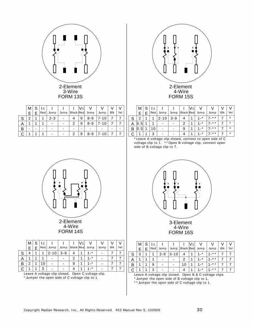
2-Element3-Wire
FORM 13S
M E
S E
I Red
I Jump
I Jump
I Black
V Red
V Jump
V Jump
V Blk
V Yel
S 2 1 1 2-3 - 4 9 8-9 7-10 7 7 A 1 1 1 - - 2 9 8-9 7-10 7 7 B - - - - - - - - - - - C 1 1 1 - - 2 9 8-9 7-10 7 7
2-Element4-Wire
FORM 14S
M E
S E
I Red
I Jump
I Jump
I Black
V Red
V Jump
V Jump
V Blk
V Yel
S 4 1 1 2-10 3-9 4 1 1-* - 7 7 A 1 1 1 - - 2 1 1-* - 7 7 B 2 1 10 - - 9 1 1-* - 7 7 C 1 1 3 - - 4 1 1-* - 7 7
Leave A voltage clip closed. Open C voltage clip. *Jumper the open side of C voltage clip to 1.
2-Element4-Wire
FORM 15S
M E
S E
I Red
I Jump
I Jump
I Black
V Red
V Jump
V Jump
V Blk
V Yel
S 2 1 1 2-10 3-9 4 1 1-* 7-** 7 * A 0.5 1 1 - - 2 1 1-* 7-** 7 * B 0.5 1 10 - - 9 1 1-* 7-** 7 * C 1 1 3 - - 4 1 1-* 7-** 7 *
*Leave A voltage clip closed, connect to open side of C voltage clip to 1. **Open B voltage clip, connect open side of B voltage clip to 7.
3-Element4-Wire
FORM 16S
M E
S E
I Red
I Jump
I Jump
I Black
V Red
V Jump
V Jump
V Blk
V Yel
S 3 1 1 2-9 3-10 4 1 1-* 1-** 7 7 A 1 1 1 - - 2 1 1-* 1-** 7 7 B 1 1 9 - - 10 1 1-* 1-** 7 7 C 1 1 3 - - 4 1 1-* 1-** 7 7
Leave A voltage clip closed. Open B & C voltage clips. *Jumper the open side of B voltage clip to 1. **Jumper the open side of C voltage clip to 1.
Copyright Radian Research, Inc., All Rights Reserved. 453 Manual Rev 5, 100906 31
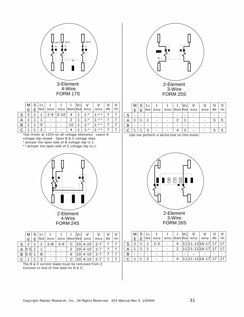
3-Element4-Wire
FORM 17S
120 V 120 V 240 V
M E
S E
I Red
I Jump
I Jump
I Black
V Red
V Jump
V Jump
V Blk
V Yel
S 3 1 1 2-9 3-10 4 1 1-* 1-** 7 7 A 1 1 1 - - 2 1 1-* 1-** 7 7 B 1 1 9 - - 10 1 1-* 1-** 7 7 C 1 1 3 - - 4 1 1-* 1-** 7 7
Test meter at 120V on all voltage elements. Leave A voltage clip closed. Open B & C voltage clips. *Jumper the open side of B voltage clip to 1. **Jumper the open side of C voltage clip to 1.
2-Element4-Wire
FORM 24S
M E
S E
I Red
I Jump
I Jump
I Black
V Red
V Jump
V Jump
V Blk
V Yel
S 2 1 1 2-B 3-9 C 10 4-10 2-7 7 7 A 0.5 1 1 - - 2 10 4-10 2-7 7 7 B 0.5 1 B - - 9 10 4-10 2-7 7 7 C 1 1 3 - - C 10 4-10 2-7 7 7
The B & C current leads must be removed from 2. Connect to end of free lead for B & C.
2-Element3-Wire
FORM 25S
M E
S E
I Red
I Jump
I Jump
I Black
V Red
V Jump
V Jump
V Blk
V Yel
S - - - - - - - - - - - A 1 1 1 - - 2 1 - - 5 5 B - - - - - - - - - - - C 1 1 3 - - 4 3 - - 5 5
Can not perform a series test on this meter.
2-Element3-Wire
FORM 26S
ZK Y
M E
S E
I Red
I Jump
I Jump
I Black
V Red
V Jump
V Jump
V Blk
V Yel
S 2 1 1 2-3 - 4 11 11-12 16-17 17 17 A 1 1 1 - - 2 11 11-12 16-17 17 17 B - - - - - - - - - - - C 1 1 2 - - 4 11 11-12 16-17 17 17
Copyright Radian Research, Inc., All Rights Reserved. 453 Manual Rev 5, 100906 32
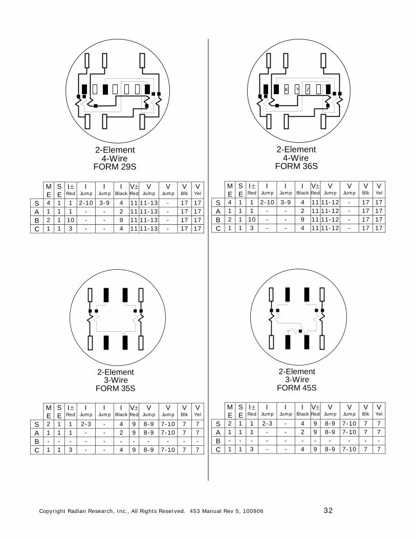
2-Element4-Wire
FORM 29S
M E
S E
I Red
I Jump
I Jump
I Black
V Red
V Jump
V Jump
V Blk
V Yel
S 4 1 1 2-10 3-9 4 11 11-13 - 17 17 A 1 1 1 - - 2 11 11-13 - 17 17 B 2 1 10 - - 9 11 11-13 - 17 17 C 1 1 3 - - 4 11 11-13 - 17 17
2-Element3-Wire
FORM 35S
M E
S E
I Red
I Jump
I Jump
I Black
V Red
V Jump
V Jump
V Blk
V Yel
S 2 1 1 2-3 - 4 9 8-9 7-10 7 7 A 1 1 1 - - 2 9 8-9 7-10 7 7 B - - - - - - - - - - - C 1 1 3 - - 4 9 8-9 7-10 7 7
2-Element4-Wire
FORM 36S
K Y Z
M E
S E
I Red
I Jump
I Jump
I Black
V Red
V Jump
V Jump
V Blk
V Yel
S 4 1 1 2-10 3-9 4 11 11-12 - 17 17 A 1 1 1 - - 2 11 11-12 - 17 17 B 2 1 10 - - 9 11 11-12 - 17 17 C 1 1 3 - - 4 11 11-12 - 17 17
2-Element3-Wire
FORM 45S
M E
S E
I Red
I Jump
I Jump
I Black
V Red
V Jump
V Jump
V Blk
V Yel
S 2 1 1 2-3 - 4 9 8-9 7-10 7 7 A 1 1 1 - - 2 9 8-9 7-10 7 7 B - - - - - - - - - - - C 1 1 3 - - 4 9 8-9 7-10 7 7
Copyright Radian Research, Inc., All Rights Reserved. 453 Manual Rev 5, 100906 33
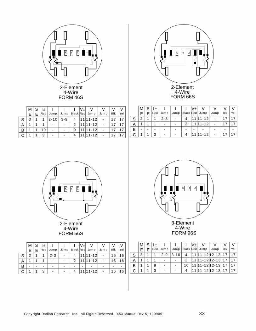
Y
2-Element4-Wire
FORM 46S
K ZY
M E
S E
I Red
I Jump
I Jump
I Black
V Red
V Jump
V Jump
V Blk
V Yel
S 3 1 1 2-10 3-9 4 11 11-12 - 17 17 A 1 1 1 - - 2 11 11-12 - 17 17 B 1 1 10 - - 9 11 11-12 - 17 17 C 1 1 3 - - 4 11 11-12 - 17 17
Y
2-Element4-Wire
FORM 56S
K ZY
M E
S E
I Red
I Jump
I Jump
I Black
V Red
V Jump
V Jump
V Blk
V Yel
S 2 1 1 2-3 - 4 11 11-12 - 16 16 A 1 1 1 - - 2 11 11-12 - 16 16 B - - - - - - - - - - - C 1 1 3 - - 4 11 11-12 - 16 16
2-Element4-Wire
FORM 66S
K Y Z
M E
S E
I Red
I Jump
I Jump
I Black
V Red
V Jump
V Jump
V Blk
V Yel
S 2 1 1 2-3 - 4 11 11-12 - 17 17 A 1 1 1 - - 2 11 11-12 - 17 17 B - - - - - - - - - - - C 1 1 3 - - 4 11 11-12 - 17 17
3-Element4-Wire
FORM 96S
YK Z
M E
S E
I Red
I Jump
I Jump
I Black
V Red
V Jump
V Jump
V Blk
V Yel
S 3 1 1 2-9 3-10 4 11 11-12 12-13 17 17 A 1 1 1 - - 2 11 11-12 12-13 17 17 B 1 1 9 - - 10 11 11-12 12-13 17 17 C 1 1 3 - - 4 11 11-12 12-13 17 17
Copyright Radian Research, Inc., All Rights Reserved. 453 Manual Rev 5, 100906 34
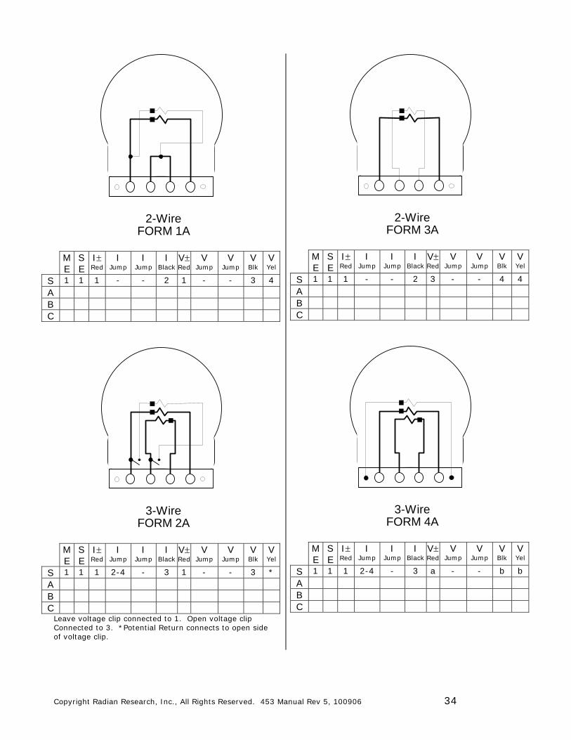
2-WireFORM 1A
M E
S E
I Red
I Jump
I Jump
I Black
V Red
V Jump
V Jump
V Blk
V Yel
S 1 1 1 - - 2 1 - - 3 4 A B C
3-WireFORM 2A
M E
S E
I Red
I Jump
I Jump
I Black
V Red
V Jump
V Jump
V Blk
V Yel
S 1 1 1 2-4 - 3 1 - - 3 * A B C
Leave voltage clip connected to 1. Open voltage clip Connected to 3. *Potential Return connects to open side of voltage clip.
2-WireFORM 3A
M E
S E
I Red
I Jump
I Jump
I Black
V Red
V Jump
V Jump
V Blk
V Yel
S 1 1 1 - - 2 3 - - 4 4 A B C
3-WireFORM 4A
M E
S E
I Red
I Jump
I Jump
I Black
V Red
V Jump
V Jump
V Blk
V Yel
S 1 1 1 2-4 - 3 a - - b b A B C
Copyright Radian Research, Inc., All Rights Reserved. 453 Manual Rev 5, 100906 35
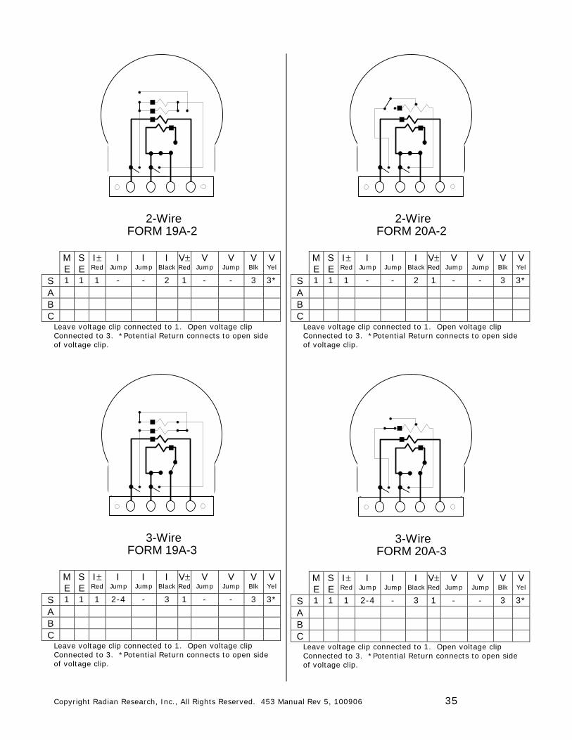
2-WireFORM 19A-2
M E
S E
I Red
I Jump
I Jump
I Black
V Red
V Jump
V Jump
V Blk
V Yel
S 1 1 1 - - 2 1 - - 3 3* A B C
Leave voltage clip connected to 1. Open voltage clip Connected to 3. *Potential Return connects to open side of voltage clip.
3-WireFORM 19A-3
M E
S E
I Red
I Jump
I Jump
I Black
V Red
V Jump
V Jump
V Blk
V Yel
S 1 1 1 2-4 - 3 1 - - 3 3* A B C
Leave voltage clip connected to 1. Open voltage clip Connected to 3. *Potential Return connects to open side of voltage clip.
2-WireFORM 20A-2
M E
S E
I Red
I Jump
I Jump
I Black
V Red
V Jump
V Jump
V Blk
V Yel
S 1 1 1 - - 2 1 - - 3 3* A B C
Leave voltage clip connected to 1. Open voltage clip Connected to 3. *Potential Return connects to open side of voltage clip.
3-WireFORM 20A-3
M E
S E
I Red
I Jump
I Jump
I Black
V Red
V Jump
V Jump
V Blk
V Yel
S 1 1 1 2-4 - 3 1 - - 3 3* A B C
Leave voltage clip connected to 1. Open voltage clip Connected to 3. *Potential Return connects to open side of voltage clip.
Copyright Radian Research, Inc., All Rights Reserved. 453 Manual Rev 5, 100906 36
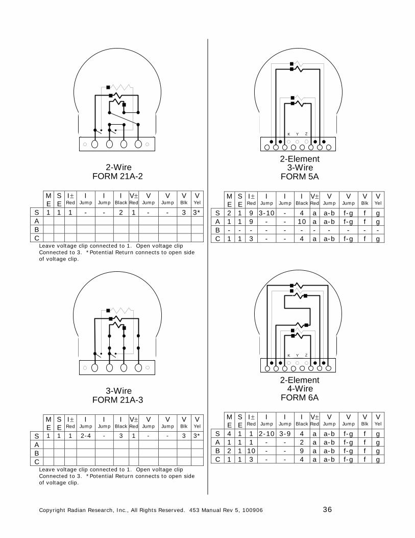
2-WireFORM 21A-2
M E
S E
I Red
I Jump
I Jump
I Black
V Red
V Jump
V Jump
V Blk
V Yel
S 1 1 1 - - 2 1 - - 3 3* A B C
Leave voltage clip connected to 1. Open voltage clip Connected to 3. *Potential Return connects to open side of voltage clip.
3-WireFORM 21A-3
M E
S E
I Red
I Jump
I Jump
I Black
V Red
V Jump
V Jump
V Blk
V Yel
S 1 1 1 2-4 - 3 1 - - 3 3* A B C
Leave voltage clip connected to 1. Open voltage clip Connected to 3. *Potential Return connects to open side of voltage clip.
2-Element3-Wire
FORM 5A
K Y Z
M E
S E
I Red
I Jump
I Jump
I Black
V Red
V Jump
V Jump
V Blk
V Yel
S 2 1 9 3-10 - 4 a a-b f-g f g A 1 1 9 - - 10 a a-b f-g f g B - - - - - - - - - - - C 1 1 3 - - 4 a a-b f-g f g
2-Element4-Wire
FORM 6A
K Y Z
M E
S E
I Red
I Jump
I Jump
I Black
V Red
V Jump
V Jump
V Blk
V Yel
S 4 1 1 2-10 3-9 4 a a-b f-g f g A 1 1 1 - - 2 a a-b f-g f g B 2 1 10 - - 9 a a-b f-g f g C 1 1 3 - - 4 a a-b f-g f g
Copyright Radian Research, Inc., All Rights Reserved. 453 Manual Rev 5, 100906 37
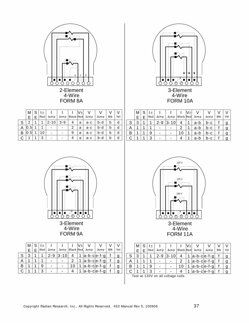
2-Element4-Wire
FORM 8A
K Y Z
M E
S E
I Red
I Jump
I Jump
I Black
V Red
V Jump
V Jump
V Blk
V Yel
S 2 1 1 2-10 3-9 4 a a-c b-d b d A 0.5 1 1 - - 2 a a-c b-d b d B 0.5 1 10 - - 9 a a-c b-d b d C 1 1 3 - - 4 a a-c b-d b d
3-Element4-Wire
FORM 9A
K
Y Z
M E
S E
I Red
I Jump
I Jump
I Black
V Red
V Jump
V Jump
V Blk
V Yel
S 3 1 1 2-9 3-10 4 1 a-b-c e-f-g f g A 1 1 1 - - 2 1 a-b-c e-f-g f g B 1 1 9 - - 10 1 a-b-c e-f-g f g C 1 1 3 - - 4 1 a-b-c e-f-g f g
3-Element4-Wire
FORM 10A
K
Y Z
M E
S E
I Red
I Jump
I Jump
I Black
V Red
V Jump
V Jump
V Blk
V Yel
S 3 1 1 2-9 3-10 4 1 a-b b-c f g A 1 1 1 - - 2 1 a-b b-c f g B 1 1 9 - - 10 1 a-b b-c f g C 1 1 3 - - 4 1 a-b b-c f g
3-Element4-Wire
FORM 11A
K
Y Z
120 V
120 V
240 V
M E
S E
I Red
I Jump
I Jump
I Black
V Red
V Jump
V Jump
V Blk
V Yel
S 3 1 1 2-9 3-10 4 1 a-b-c e-f-g f g A 1 1 1 - - 2 1 a-b-c e-f-g f g B 1 1 9 - - 10 1 a-b-c e-f-g f g C 1 1 3 - - 4 1 a-b-c e-f-g f g
Test at 120V on all voltage coils.
Copyright Radian Research, Inc., All Rights Reserved. 453 Manual Rev 5, 100906 38
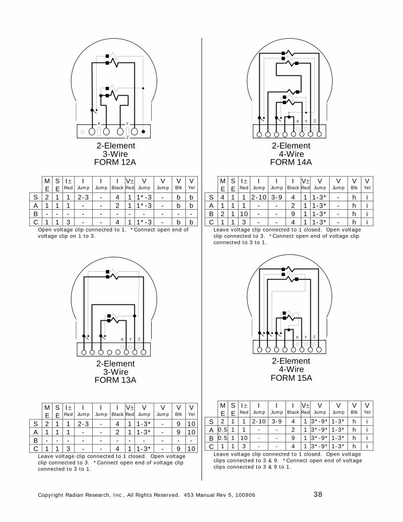
3-WireFORM 12A
2-Element
K Y
Z
M E
S E
I Red
I Jump
I Jump
I Black
V Red
V Jump
V Jump
V Blk
V Yel
S 2 1 1 2-3 - 4 1 1*-3 - b b A 1 1 1 - - 2 1 1*-3 - b b B - - - - - - - - - - - C 1 1 3 - - 4 1 1*-3 - b b
Open voltage clip connected to 1. *Connect open end of voltage clip on 1 to 3.
2-Element3-Wire
FORM 13A
K Y Z
M E
S E
I Red
I Jump
I Jump
I Black
V Red
V Jump
V Jump
V Blk
V Yel
S 2 1 1 2-3 - 4 1 1-3* - 9 10 A 1 1 1 - - 2 1 1-3* - 9 10 B - - - - - - - - - - - C 1 1 3 - - 4 1 1-3* - 9 10
Leave voltage clip connected to 1 closed. Open voltage clip connected to 3. *Connect open end of voltage clip connected to 3 to 1.
2-Element4-Wire
FORM 14A
K Y Z
M E
S E
I Red
I Jump
I Jump
I Black
V Red
V Jump
V Jump
V Blk
V Yel
S 4 1 1 2-10 3-9 4 1 1-3* - h i A 1 1 1 - - 2 1 1-3* - h i B 2 1 10 - - 9 1 1-3* - h i C 1 1 3 - - 4 1 1-3* - h i
Leave voltage clip connected to 1 closed. Open voltage clip connected to 3. *Connect open end of voltage clip connected to 3 to 1.
2-Element4-Wire
FORM 15A
K Y Z
M E
S E
I Red
I Jump
I Jump
I Black
V Red
V Jump
V Jump
V Blk
V Yel
S 2 1 1 2-10 3-9 4 1 3*-9* 1-3* h i A 0.5 1 1 - - 2 1 3*-9* 1-3* h i B 0.5 1 10 - - 9 1 3*-9* 1-3* h i C 1 1 3 - - 4 1 3*-9* 1-3* h i
Leave voltage clip connected to 1 closed. Open voltage clips connected to 3 & 9. *Connect open end of voltage clips connected to 3 & 9 to 1.
Copyright Radian Research, Inc., All Rights Reserved. 453 Manual Rev 5, 100906 39
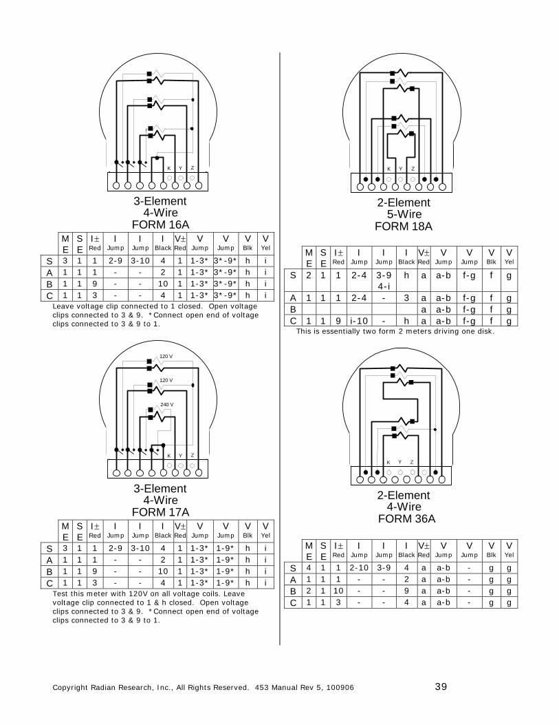
3-Element4-Wire
FORM 16A
K Y Z
M E
S E
I Red
I Jump
I Jump
I Black
V Red
V Jump
V Jump
V Blk
V Yel
S 3 1 1 2-9 3-10 4 1 1-3* 3*-9* h i A 1 1 1 - - 2 1 1-3* 3*-9* h i B 1 1 9 - - 10 1 1-3* 3*-9* h i C 1 1 3 - - 4 1 1-3* 3*-9* h i
Leave voltage clip connected to 1 closed. Open voltage clips connected to 3 & 9. *Connect open end of voltage clips connected to 3 & 9 to 1.
3-Element4-Wire
FORM 17A
K Y Z
120 V
120 V
240 V
M E
S E
I Red
I Jump
I Jump
I Black
V Red
V Jump
V Jump
V Blk
V Yel
S 3 1 1 2-9 3-10 4 1 1-3* 1-9* h i A 1 1 1 - - 2 1 1-3* 1-9* h i B 1 1 9 - - 10 1 1-3* 1-9* h i C 1 1 3 - - 4 1 1-3* 1-9* h i
Test this meter with 120V on all voltage coils. Leave voltage clip connected to 1 & h closed. Open voltage clips connected to 3 & 9. *Connect open end of voltage clips connected to 3 & 9 to 1.
2-Element5-Wire
FORM 18A
K Y Z
M E
S E
I Red
I Jump
I Jump
I Black
V Red
V Jump
V Jump
V Blk
V Yel
S 2 1 1 2-4 3-9 4-i
h a a-b f-g f g
A 1 1 1 2-4 - 3 a a-b f-g f g B a a-b f-g f g C 1 1 9 i-10 - h a a-b f-g f g
This is essentially two form 2 meters driving one disk.
2-Element 4-Wire
FORM 36A
K Y Z
M E
S E
I Red
I Jump
I Jump
I Black
V Red
V Jump
V Jump
V Blk
V Yel
S 4 1 1 2-10 3-9 4 a a-b - g g A 1 1 1 - - 2 a a-b - g g B 2 1 10 - - 9 a a-b - g g C 1 1 3 - - 4 a a-b - g g
Copyright Radian Research, Inc., All Rights Reserved. 453 Manual Rev 5, 100906 40
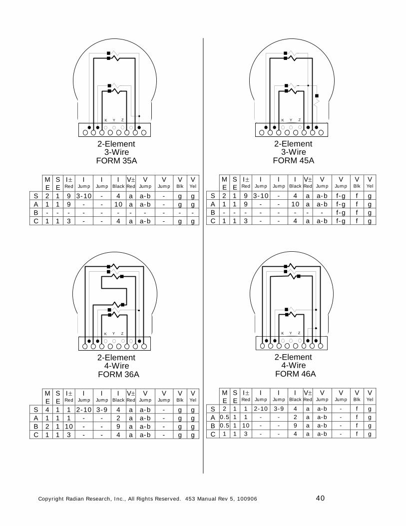
2-Element3-Wire
FORM 35A
K Y Z
M E
S E
I Red
I Jump
I Jump
I Black
V Red
V Jump
V Jump
V Blk
V Yel
S 2 1 9 3-10 - 4 a a-b - g g A 1 1 9 - - 10 a a-b - g g B - - - - - - - - - - - C 1 1 3 - - 4 a a-b - g g
2-Element4-Wire
FORM 36A
K Y Z
M E
S E
I Red
I Jump
I Jump
I Black
V Red
V Jump
V Jump
V Blk
V Yel
S 4 1 1 2-10 3-9 4 a a-b - g g A 1 1 1 - - 2 a a-b - g g B 2 1 10 - - 9 a a-b - g g C 1 1 3 - - 4 a a-b - g g
2-Element3-Wire
FORM 45A
K Y Z
M E
S E
I Red
I Jump
I Jump
I Black
V Red
V Jump
V Jump
V Blk
V Yel
S 2 1 9 3-10 - 4 a a-b f-g f g A 1 1 9 - - 10 a a-b f-g f g B - - - - - - - - f-g f g C 1 1 3 - - 4 a a-b f-g f g
2-Element4-Wire
FORM 46A
K Y Z
M E
S E
I Red
I Jump
I Jump
I Black
V Red
V Jump
V Jump
V Blk
V Yel
S 2 1 1 2-10 3-9 4 a a-b - f g A 0.5 1 1 - - 2 a a-b - f g B 0.5 1 10 - - 9 a a-b - f g C 1 1 3 - - 4 a a-b - f g
Copyright Radian Research, Inc., All Rights Reserved. 453 Manual Rev 5, 100906 41
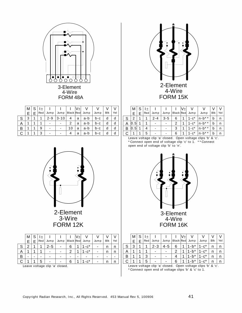
3-Element4-Wire
FORM 48A
M E
S E
I Red
I Jump
I Jump
I Black
V Red
V Jump
V Jump
V Blk
V Yel
S 3 1 1 2-9 3-10 4 a a-b b-c d d A 1 1 1 - - 2 a a-b b-c d d B 1 1 9 - - 10 a a-b b-c d d C 1 1 3 - - 4 a a-b b-c d d
2-Element3-Wire
FORM 12K
M E
S E
I Red
I Jump
I Jump
I Black
V Red
V Jump
V Jump
V Blk
V Yel
S 2 1 1 2-5 - 6 1 1-c* - n n A 1 1 1 - - 2 1 1-c* - n n B - - - - - - - - - - - C 1 1 5 - - 6 1 1-c* - n n
Leave voltage clip ‘a’ closed.
2-Element4-Wire
FORM 15K
M E
S E
I Red
I Jump
I Jump
I Black
V Red
V Jump
V Jump
V Blk
V Yel
S 2 1 1 2-4 3-5 6 1 1-c* n-b** b n A 0.5 1 1 - - 2 1 1-c* n-b** b n B 0.5 1 4 - - 3 1 1-c* n-b** b n C 1 1 5 - - 6 1 1-c* n-b** b n
Leave voltage clip ‘a’ closed. Open voltage clips ‘b’ & ‘c’. *Connect open end of voltage clip ‘c’ to 1. **Connect open end of voltage clip ‘b’ to ‘n’.
3-Element4-Wire
FORM 16K
M E
S E
I Red
I Jump
I Jump
I Black
V Red
V Jump
V Jump
V Blk
V Yel
S 3 1 1 2-3 4-5 6 1 1-b* 1-c* n n A 1 1 1 - - 2 1 1-b* 1-c* n n B 1 1 3 - - 4 1 1-b* 1-c* n n C 1 1 5 - - 6 1 1-b* 1-c* n n
Leave voltage clip ‘a’ closed. Open voltage clips ‘b’ & ‘c’. *Connect open end of voltage clips ‘b’ & ‘c’ to 1.
Copyright Radian Research, Inc., All Rights Reserved. 453 Manual Rev 5, 100906 42
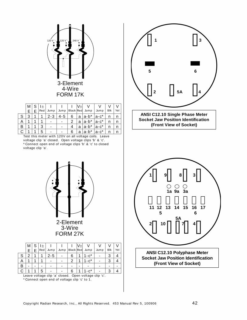
3-Element4-Wire
FORM 17K
120 V 240 V120 V
M E
S E
I Red
I Jump
I Jump
I Black
V Red
V Jump
V Jump
V Blk
V Yel
S 3 1 1 2-3 4-5 6 a a-b* a-c* n n A 1 1 1 - - 2 a a-b* a-c* n n B 1 1 3 - - 4 a a-b* a-c* n n C 1 1 5 - - 6 a a-b* a-c* n n
Test this meter with 120V on all voltage coils. Leave voltage clip ‘a’ closed. Open voltage clips ‘b’ & ‘c’. *Connect open end of voltage clips ‘b’ & ‘c’ to closed voltage clip ‘a’.
2-Element3-Wire
FORM 27K
M E
S E
I Red
I Jump
I Jump
I Black
V Red
V Jump
V Jump
V Blk
V Yel
S 2 1 1 2-5 - 6 1 1-c* - 3 4 A 1 1 1 - - 2 1 1-c* - 3 4 B - - - - - - - - - - - C 1 1 5 - - 6 1 1-c* - 3 4
Leave voltage clip ‘a’ closed. Open voltage clip ‘c’. *Connect open end of voltage clip ‘c’ to 1.
1 3
5 6
2 5A 4
ANSI C12.10 Single Phase MeterSocket Jaw Position Identification
(Front View of Socket)
1 9 8 3
1a 9a 3a
11 12 13 14 15 16 17 5 6 5A2 10 7 4
ANSI C12.10 Polyphase MeterSocket Jaw Position Identification
(Front View of Socket)
Copyright Radian Research, Inc., All Rights Reserved. 453 Manual Rev 5, 100906 43
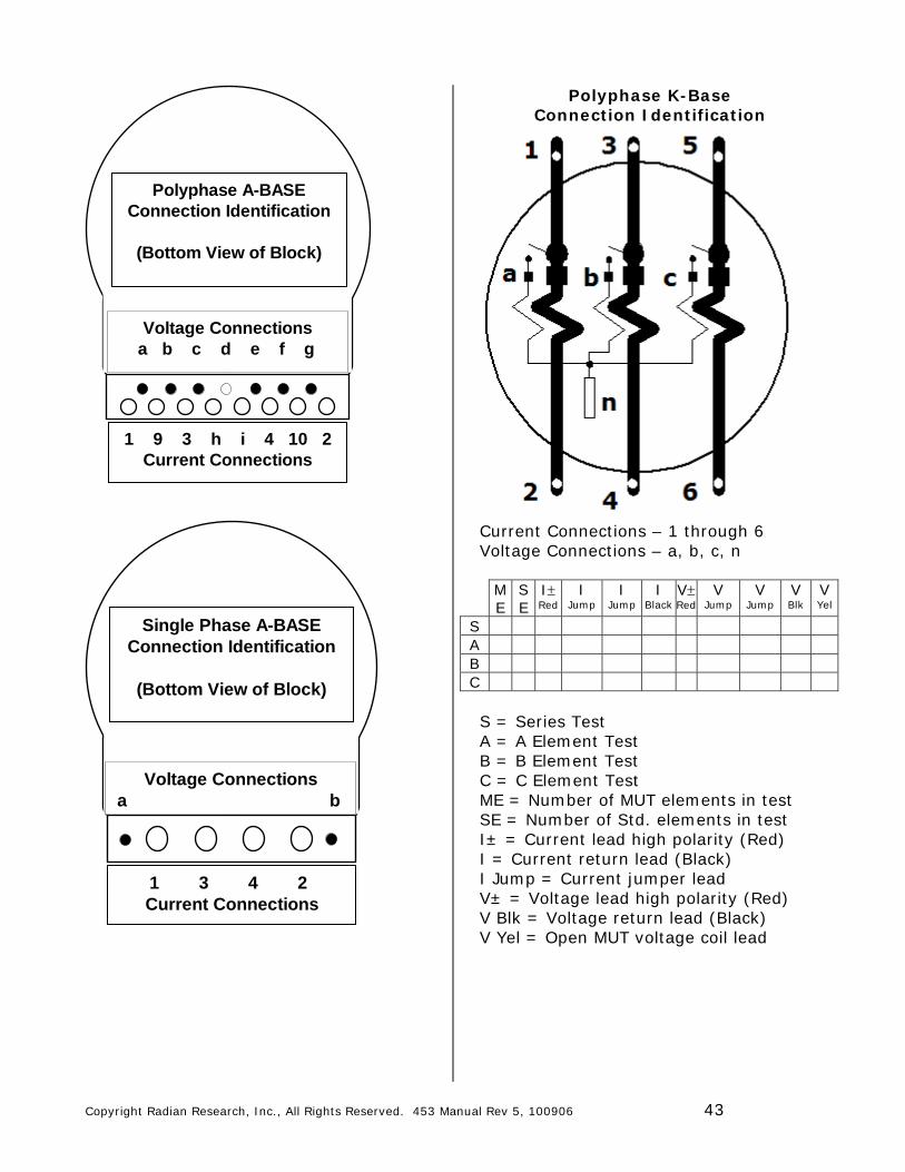
Voltage Connections a b c d e f g
1 9 3 h i 4 10 2Current Connections
Polyphase A-BASEConnection Identification
(Bottom View of Block)
Voltage Connectionsa b
1 3 4 2Current Connections
Single Phase A-BASEConnection Identification
(Bottom View of Block)
Polyphase K-Base Connection Identification
Current Connections – 1 through 6 Voltage Connections – a, b, c, n
M E
S E
I Red
I Jump
I Jump
I Black
V Red
V Jump
V Jump
V Blk
V Yel
S A B C S = Series Test A = A Element Test B = B Element Test C = C Element Test ME = Number of MUT elements in test SE = Number of Std. elements in test I± = Current lead high polarity (Red) I = Current return lead (Black) I Jump = Current jumper lead V± = Voltage lead high polarity (Red) V Blk = Voltage return lead (Black) V Yel = Open MUT voltage coil lead
BULLETIN 102
Copyright © Radian Research, Inc. – 2006. All rights reserved. 44 011005 Document Revision 1.2
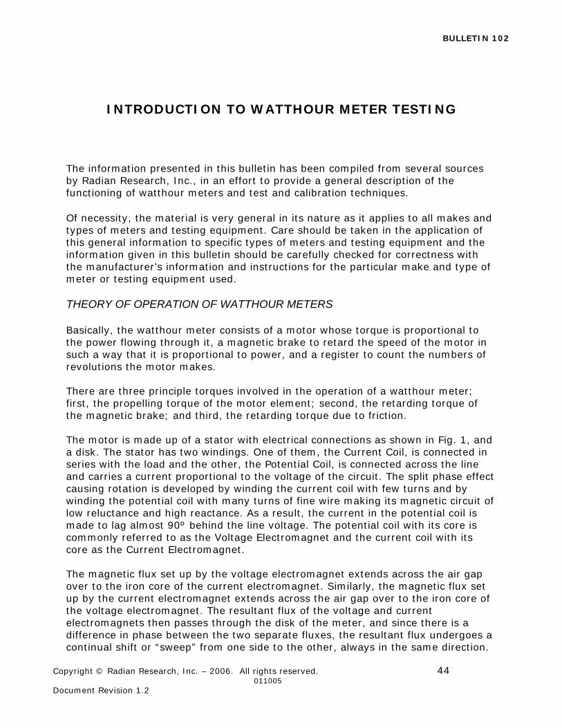
INTRODUCTION TO WATTHOUR METER TESTING The information presented in this bulletin has been compiled from several sources by Radian Research, Inc., in an effort to provide a general description of the functioning of watthour meters and test and calibration techniques. Of necessity, the material is very general in its nature as it applies to all makes and types of meters and testing equipment. Care should be taken in the application of this general information to specific types of meters and testing equipment and the information given in this bulletin should be carefully checked for correctness with the manufacturer’s information and instructions for the particular make and type of meter or testing equipment used. THEORY OF OPERATION OF WATTHOUR METERS Basically, the watthour meter consists of a motor whose torque is proportional to the power flowing through it, a magnetic brake to retard the speed of the motor in such a way that it is proportional to power, and a register to count the numbers of revolutions the motor makes. There are three principle torques involved in the operation of a watthour meter; first, the propelling torque of the motor element; second, the retarding torque of the magnetic brake; and third, the retarding torque due to friction. The motor is made up of a stator with electrical connections as shown in Fig. 1, and a disk. The stator has two windings. One of them, the Current Coil, is connected in series with the load and the other, the Potential Coil, is connected across the line and carries a current proportional to the voltage of the circuit. The split phase effect causing rotation is developed by winding the current coil with few turns and by winding the potential coil with many turns of fine wire making its magnetic circuit of low reluctance and high reactance. As a result, the current in the potential coil is made to lag almost 90º behind the line voltage. The potential coil with its core is commonly referred to as the Voltage Electromagnet and the current coil with its core as the Current Electromagnet. The magnetic flux set up by the voltage electromagnet extends across the air gap over to the iron core of the current electromagnet. Similarly, the magnetic flux set up by the current electromagnet extends across the air gap over to the iron core of the voltage electromagnet. The resultant flux of the voltage and current electromagnets then passes through the disk of the meter, and since there is a difference in phase between the two separate fluxes, the resultant flux undergoes a continual shift or “sweep” from one side to the other, always in the same direction.
BULLETIN 102
Copyright © Radian Research, Inc. – 2006. All rights reserved. 45 011005 Document Revision 1.2
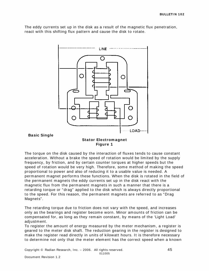
The eddy currents set up in the disk as a result of the magnetic flux penetration, react with this shifting flux pattern and cause the disk to rotate.
Basic Single Stator Electromagnet
Figure 1 The torque on the disk caused by the interaction of fluxes tends to cause constant acceleration. Without a brake the speed of rotation would be limited by the supply frequency, by friction, and by certain counter torques at higher speeds but the speed of rotation would be very high. Therefore, some method of making the speed proportional to power and also of reducing it to a usable value is needed. A permanent magnet performs these functions. When the disk is rotated in the field of the permanent magnets the eddy currents set up in the disk react with the magnetic flux from the permanent magnets in such a manner that there is a retarding torque or “drag” applied to the disk which is always directly proportional to the speed. For this reason, the permanent magnets are referred to as “Drag Magnets”. The retarding torque due to friction does not vary with the speed, and increases only as the bearings and register become worn. Minor amounts of friction can be compensated for, as long as they remain constant, by means of the ‘Light Load’ adjustment. To register the amount of energy measured by the meter mechanism, a register is geared to the meter disk shaft. The reduction gearing in the register is designed to make the register read directly in units of kilowatt hours. It is therefore necessary to determine not only that the meter element has the correct speed when a known
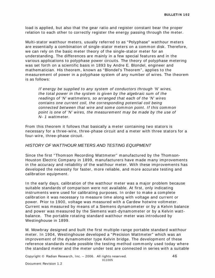
BULLETIN 102
Copyright © Radian Research, Inc. – 2006. All rights reserved. 46 011005 Document Revision 1.2
load is applied, but also that the gear ratio and register constant bear the proper relation to each other to correctly register the energy passing through the meter.
Multi-stator watthour meters, usually referred to as “Polyphase” watthour meters are essentially a combination of single-stator meters on a common disk. Therefore, we can rely on the basic meter theory of the single-stator meter for an understanding. The differences are mainly in a few special features and in the various applications to polyphase power circuits. The theory of polyphase metering was set forth on a scientific basis in 1893 by Andre E. Blondel, engineer and mathematician. His theorem, known as “Blondel’s Theorem”, applies to the measurement of power in a polyphase system of any number of wires. The theorem is as follows:
If energy be supplied to any system of conductors through ‘N’ wires, the total power in the system is given by the algebraic sum of the readings of ‘N’ wattmeters, so arranged that each of the ‘N’ wires contains one current coil, the corresponding potential coil being connected between that wire and some common point. If this common point is one of ‘N’ wires, the measurement may be made by the use of N- 1 wattmeter.
From this theorem it follows that basically a meter containing two stators is necessary for a three-wire, three-phase circuit and a meter with three stators for a four-wire, three-phase circuit. HISTORY OF WATTHOUR METERS AND TESTING EQUIPMENT Since the first “Thomson Recording Wattmeter” manufactured by the Thomson-Houston Electric Company in 1899, manufacturers have made many improvements in the accuracy and reliability of the watthour meter. With these improvements has developed the necessity for faster, more reliable, and more accurate testing and calibration equipment. In the early days, calibration of the watthour meter was a major problem because suitable standards of comparison were not available. At first, only indicating instruments were used for calibrating purposes. In order to make a complete calibration it was necessary to measure time along with voltage and current or power. Prior to 1900, voltage was measured with a Cardew hotwire voltmeter. Current was measured by means of a Siemens dynamometer or by a Kelvin balance and power was measured by the Siemens watt-dynamometer or by a Kelvin watt-balance. The portable rotating standard watthour meter was introduced by Westinghouse in 1899. M. Mowbray designed and built the first multiple-range portable standard watthour meter. In 1904, Westinghouse developed a “Precision Wattmeter” which was an improvement of the dynamometer type Kelvin bridge. The development of these reference standards made possible the testing method commonly used today where the standard meter and the meter under test are connected in series with a suitable

BULLETIN 102
Copyright © Radian Research, Inc. – 2006. All rights reserved. 47 011005 Document Revision 1.2
load. This method of testing greatly speeded up the calibration procedure since any fluctuations in load affected the meter and standard alike and therefore did not alter the result.
In the late 1920’s it was realized that the tremendous increase in the number of meters in service necessitated more efficient methods of testing to maintain the high standards set for metering electric energy. Testing of meters on the customer’s premises was a slow and costly process. In many sections of the United States, it became increasingly apparent that more satisfactory results could be obtained by testing large quantities of meters in centralized shops where automatic test equipment could be used. By 1925, development in electronic devices had progressed to the point where their use as auxiliaries in the testing process gave promise of both greater speed and accuracy. The first electronic development was in 1925 by A.R. Rutter of Westinghouse. This development used a photoelectric device cut by holes in a meter disk to produce marks on a printed tape that were compared to master clock marks to determine the speed of the meter. In 1927, H. P. Sparks, also of Westinghouse developed the use of the stroboscopic principle which allowed the meter to be adjusted visually, without the necessity of counting revolutions. By 1940, some utilities had developed watthour meter test boards that were essentially fully automatic. In 1960, Weston Instruments developed the inductronic wattmeter which was the first electronic wattmeter. Also in the ‘60’s the single revolution method of calibrating watthour meters and the application of using digital counters was. introduced. In 1968 a method for computer-controlled meter calibration was patented by Duncan Electric (Landis & Gyr). By 1969 photoelectric test equipment utilizing programming for sequence of tests, computers to calculate meter accuracy, digital readout and printout of meter accuracies, and solid-state circuitry was being widely used in test equipment designs. In the early 1980’s a method of generating the precision voltage and current using solid state amplifiers was introduced by test equipment manufacturers. This method eliminated the testing problems associated with watthour meter burden affecting the accuracy of the test system and allowed precise control of the phase angle between the current and voltage. Further improvements in the reference standard were made by Radian Research by their introduction of a fully auto-ranging ‘summing’ reference standard with three current circuits making possible the testing of watthour meters with the potential clips closed. All of these improvements have made testing equipment faster, more accurate, more dependable, and more versatile.
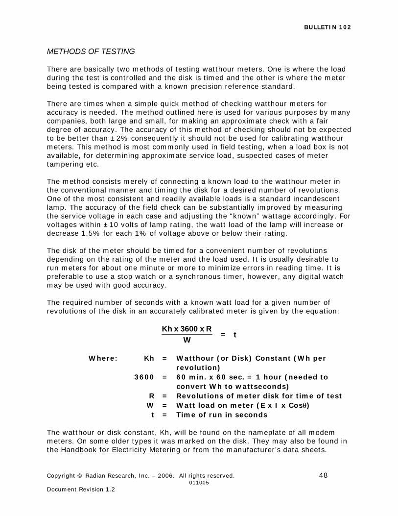
BULLETIN 102
Copyright © Radian Research, Inc. – 2006. All rights reserved. 48 011005 Document Revision 1.2
METHODS OF TESTING There are basically two methods of testing watthour meters. One is where the load during the test is controlled and the disk is timed and the other is where the meter being tested is compared with a known precision reference standard. There are times when a simple quick method of checking watthour meters for accuracy is needed. The method outlined here is used for various purposes by many companies, both large and small, for making an approximate check with a fair degree of accuracy. The accuracy of this method of checking should not be expected to be better than ±2% consequently it should not be used for calibrating watthour meters. This method is most commonly used in field testing, when a load box is not available, for determining approximate service load, suspected cases of meter tampering etc. The method consists merely of connecting a known load to the watthour meter in the conventional manner and timing the disk for a desired number of revolutions. One of the most consistent and readily available loads is a standard incandescent lamp. The accuracy of the field check can be substantially improved by measuring the service voltage in each case and adjusting the “known” wattage accordingly. For voltages within ±10 volts of lamp rating, the watt load of the lamp will increase or decrease 1.5% for each 1% of voltage above or below their rating. The disk of the meter should be timed for a convenient number of revolutions depending on the rating of the meter and the load used. It is usually desirable to run meters for about one minute or more to minimize errors in reading time. It is preferable to use a stop watch or a synchronous timer, however, any digital watch may be used with good accuracy. The required number of seconds with a known watt load for a given number of revolutions of the disk in an accurately calibrated meter is given by the equation:
t=W
Rx3600xKh
Where: Kh = Watthour (or Disk) Constant (Wh per
revolution) 3600 = 60 min. x 60 sec. = 1 hour (needed to
convert Wh to wattseconds) R = Revolutions of meter disk for time of test W = Watt load on meter (E x I x Cos) t = Time of run in seconds
The watthour or disk constant, Kh, will be found on the nameplate of all modem meters. On some older types it was marked on the disk. They may also be found in the Handbook for Electricity Metering or from the manufacturer’s data sheets.
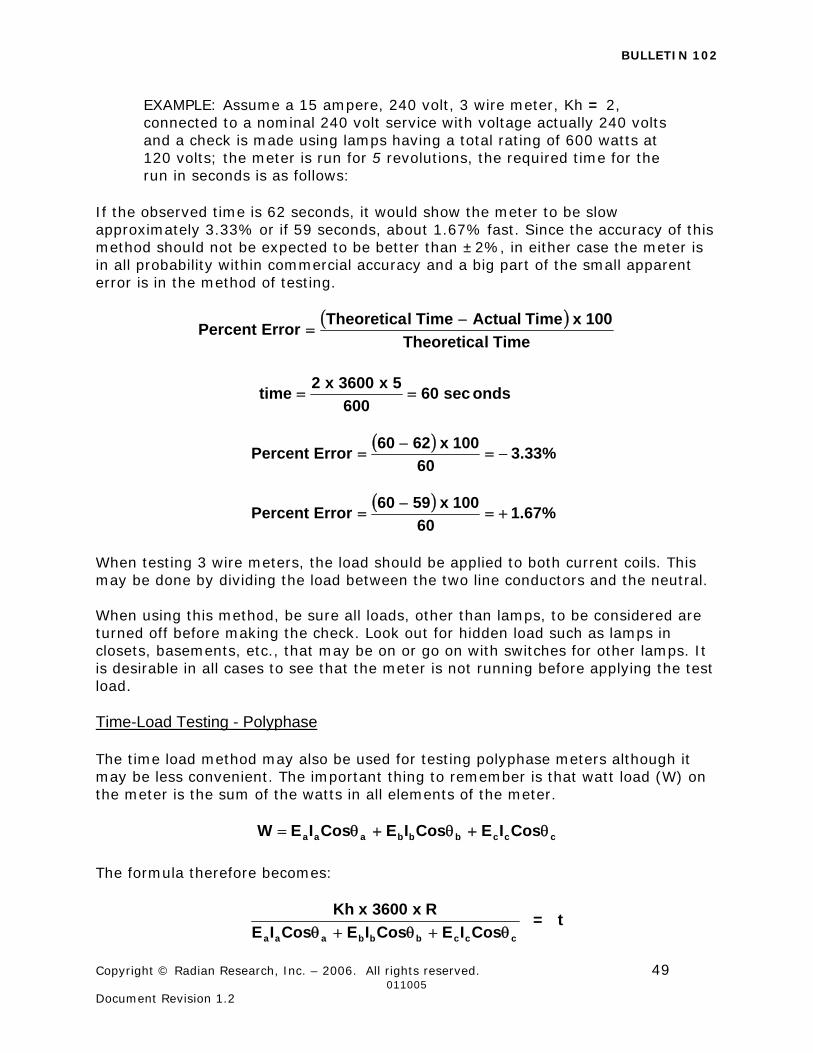
BULLETIN 102
Copyright © Radian Research, Inc. – 2006. All rights reserved. 49 011005 Document Revision 1.2
EXAMPLE: Assume a 15 ampere, 240 volt, 3 wire meter, Kh = 2, connected to a nominal 240 volt service with voltage actually 240 volts and a check is made using lamps having a total rating of 600 watts at 120 volts; the meter is run for 5 revolutions, the required time for the run in seconds is as follows:
If the observed time is 62 seconds, it would show the meter to be slow approximately 3.33% or if 59 seconds, about 1.67% fast. Since the accuracy of this method should not be expected to be better than ±2%, in either case the meter is in all probability within commercial accuracy and a big part of the small apparent error is in the method of testing.
TimelTheoretica
100xTimeActualTimelTheoreticaErrorPercent
%33.360
100x6260ErrorPercent
%67.160
100x5960ErrorPercent
When testing 3 wire meters, the load should be applied to both current coils. This may be done by dividing the load between the two line conductors and the neutral. When using this method, be sure all loads, other than lamps, to be considered are turned off before making the check. Look out for hidden load such as lamps in closets, basements, etc., that may be on or go on with switches for other lamps. It is desirable in all cases to see that the meter is not running before applying the test load. Time-Load Testing - Polyphase The time load method may also be used for testing polyphase meters although it may be less convenient. The important thing to remember is that watt load (W) on the meter is the sum of the watts in all elements of the meter.
cccbbbaaa CosIECosIECosIEW
The formula therefore becomes:
cccbbbaaa CosIECosIECosIE
Rx3600xKh
= t
ondssec60600
5x3600x2time
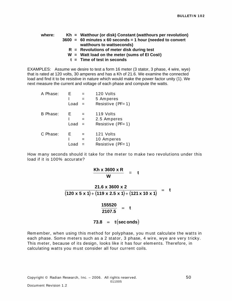
BULLETIN 102
Copyright © Radian Research, Inc. – 2006. All rights reserved. 50 011005 Document Revision 1.2
where: Kh = Watthour (or disk) Constant (watthours per revolution) 3600 = 60 minutes x 60 seconds = 1 hour (needed to convert watthours to wattseconds) R = Revolutions of meter disk during test W = Watt load on the meter (sums of EI Cos) t = Time of test in seconds
EXAMPLES: Assume we desire to test a form 16 meter (3 stator, 3 phase, 4 wire, wye) that is rated at 120 volts, 30 amperes and has a Kh of 21.6. We examine the connected load and find it to be resistive in nature which would make the power factor unity (1). We next measure the current and voltage of each phase and compute the watts. A Phase: E = 120 Volts I = 5 Amperes Load = Resistive (PF=1) B Phase: E = 119 Volts I = 2.5 Amperes Load = Resistive (PF=1) C Phase: E = 121 Volts I = 10 Amperes Load = Resistive (PF=1) How many seconds should it take for the meter to make two revolutions under this load if it is 100% accurate?
W
Rx3600xKh = t
t1x10x1211x5.2x1191x5x120
2x3600x6.21
t5.2107
155520
ondssect8.73
Remember, when using this method for polyphase, you must calculate the watts in each phase. Some meters such as a 2 stator, 3 phase, 4 wire, wye are very tricky. This meter, because of its design, looks like it has four elements. Therefore, in calculating watts you must consider all four current coils.
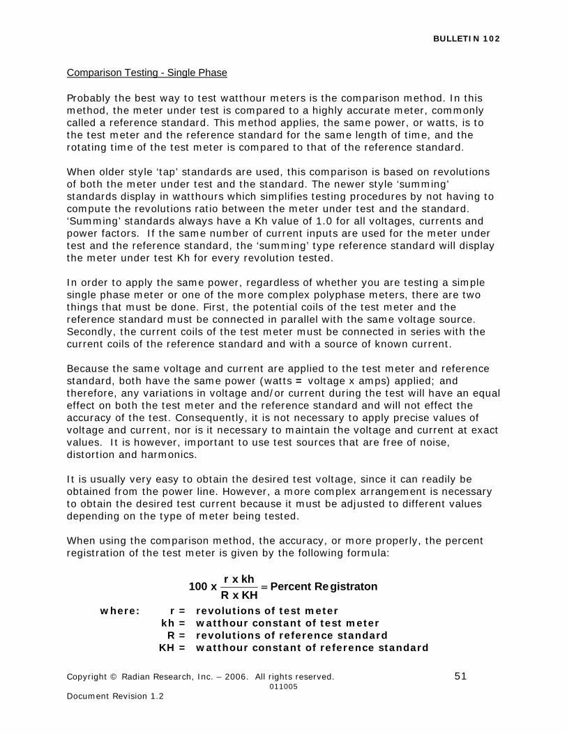
BULLETIN 102
Copyright © Radian Research, Inc. – 2006. All rights reserved. 51 011005 Document Revision 1.2
Comparison Testing - Single Phase Probably the best way to test watthour meters is the comparison method. In this method, the meter under test is compared to a highly accurate meter, commonly called a reference standard. This method applies, the same power, or watts, is to the test meter and the reference standard for the same length of time, and the rotating time of the test meter is compared to that of the reference standard. When older style ‘tap’ standards are used, this comparison is based on revolutions of both the meter under test and the standard. The newer style ‘summing’ standards display in watthours which simplifies testing procedures by not having to compute the revolutions ratio between the meter under test and the standard. ‘Summing’ standards always have a Kh value of 1.0 for all voltages, currents and power factors. If the same number of current inputs are used for the meter under test and the reference standard, the ‘summing’ type reference standard will display the meter under test Kh for every revolution tested. In order to apply the same power, regardless of whether you are testing a simple single phase meter or one of the more complex polyphase meters, there are two things that must be done. First, the potential coils of the test meter and the reference standard must be connected in parallel with the same voltage source. Secondly, the current coils of the test meter must be connected in series with the current coils of the reference standard and with a source of known current. Because the same voltage and current are applied to the test meter and reference standard, both have the same power (watts = voltage x amps) applied; and therefore, any variations in voltage and/or current during the test will have an equal effect on both the test meter and the reference standard and will not effect the accuracy of the test. Consequently, it is not necessary to apply precise values of voltage and current, nor is it necessary to maintain the voltage and current at exact values. It is however, important to use test sources that are free of noise, distortion and harmonics. It is usually very easy to obtain the desired test voltage, since it can readily be obtained from the power line. However, a more complex arrangement is necessary to obtain the desired test current because it must be adjusted to different values depending on the type of meter being tested. When using the comparison method, the accuracy, or more properly, the percent registration of the test meter is given by the following formula:
gistratonRePercentKHxR
khxrx100
where: r = revolutions of test meter kh = watthour constant of test meter R = revolutions of reference standard KH = watthour constant of reference standard
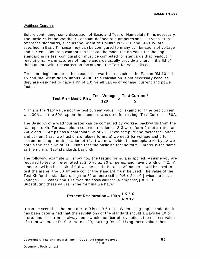
BULLETIN 102
Copyright © Radian Research, Inc. – 2006. All rights reserved. 52 011005 Document Revision 1.2
Watthour Constant Before continuing, some discussion of Basic and Test or Nameplate Kh is necessary. The Basic Kh is the Watthour Constant defined at 5 amperes and 120 volts. ‘Tap’ reference standards, such as the Scientific Columbus SC-10 and SC-10V, are specified in Basic Kh since they can be configured to many combinations of voltage and current. Before a comparison test can be made the Kh value for the ‘tap’ standard in its test configuration must be computed for standards that readout in revolutions. Manufacturers of ‘tap’ standards usually provide a chart in the lid of the standard with the correction factors and the Test Kh values listed. For ‘summing’ standards that readout in watthours, such as the Radian RM-10, 11, 15 and the Scientific Columbus SC-30, this calculation is not necessary because they are designed to have a Kh of 1.0 for all values of voltage, current and power factor.
5
*CurrentTestx
120
VoltageTestxKhBasicKhTest
* This is the ‘tap’ value not the test current value. For example: if the test current was 30A and the 50A tap on the standard was used for testing; Test Current = 50A. The Basic Kh of a watthour meter can be computed by working backwards from the Nameplate Kh. For example, a common residential 2-3 wire, form 2 meter rated at 240V and 30 Amps has a nameplate Kh of 7.2. If we compute the factor for voltage and current (last two fractions of above formula) we get 2 for voltage and 6 for current making a multiplication of 12. If we now divide the nameplate Kh by 12 we obtain the basic Kh of 0.6. Note that the basic Kh for the form 2 meter is the same as the normal ‘tap’ standards basic Kh. The following example will show how the testing formula is applied. Assume you are required to test a meter rated at 240 volts, 30 amperes, and having a Kh of 7.2. A standard with a basic Kh of 0.6 will be used. Because 30 amperes will be used to test the meter, the 50 ampere coil of the standard must be used. The value of the Test Kh for the standard using the 50 ampere coil is 0.6 x 2 x 10 [twice the basic voltage (120 volts) and 10 times the basic current (5 amperes)] = 12.0. Substituting these values in the formula we have:
12xR
2.7xrx100gistrationRePercent
It can be seen that the ratio of r to R is as 0.6 to 1. When using ‘tap’ standards, it has been determined that the revolutions of the standard should always be 10 or more, and since r must always be a whole number of revolutions the nearest value of r that will make R 10 or more is 20, making R= 12. Using these values then:
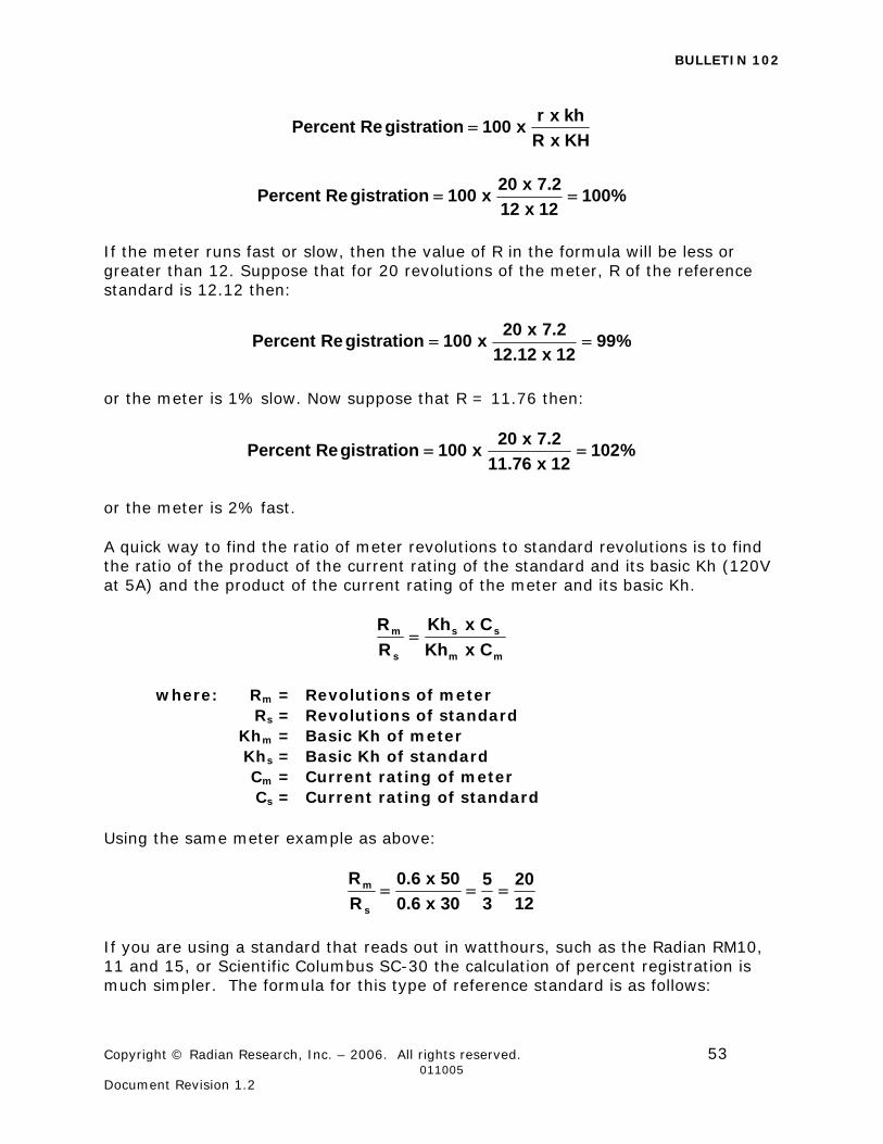
BULLETIN 102
Copyright © Radian Research, Inc. – 2006. All rights reserved. 53 011005 Document Revision 1.2
KHxR
khxrx100gistrationRePercent
%10012x12
2.7x20x100gistrationRePercent
If the meter runs fast or slow, then the value of R in the formula will be less or greater than 12. Suppose that for 20 revolutions of the meter, R of the reference standard is 12.12 then:
%9912x12.12
2.7x20x100gistrationRePercent
or the meter is 1% slow. Now suppose that R = 11.76 then:
%10212x76.11
2.7x20x100gistrationRePercent
or the meter is 2% fast.
A quick way to find the ratio of meter revolutions to standard revolutions is to find the ratio of the product of the current rating of the standard and its basic Kh (120V at 5A) and the product of the current rating of the meter and its basic Kh.
mm
ss
s
m
CxKh
CxKh
R
R
where: Rm = Revolutions of meter Rs = Revolutions of standard Khm = Basic Kh of meter Khs = Basic Kh of standard Cm = Current rating of meter Cs = Current rating of standard
Using the same meter example as above:
12
20
3
5
30x6.0
50x6.0
R
R
s
m
If you are using a standard that reads out in watthours, such as the Radian RM10, 11 and 15, or Scientific Columbus SC-30 the calculation of percent registration is much simpler. The formula for this type of reference standard is as follows:
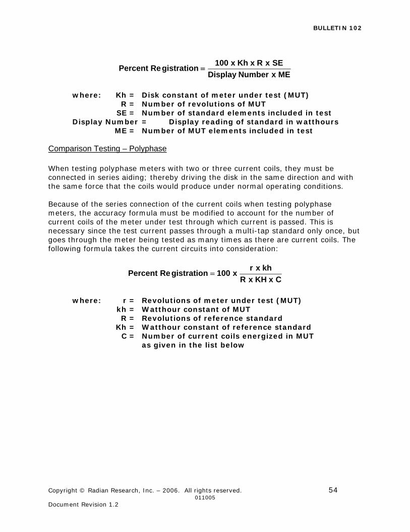
BULLETIN 102
Copyright © Radian Research, Inc. – 2006. All rights reserved. 54 011005 Document Revision 1.2
MExNumberDisplay
SExRxKhx100gistrationRePercent
where: Kh = Disk constant of meter under test (MUT) R = Number of revolutions of MUT SE = Number of standard elements included in test Display Number = Display reading of standard in watthours ME = Number of MUT elements included in test
Comparison Testing – Polyphase When testing polyphase meters with two or three current coils, they must be connected in series aiding; thereby driving the disk in the same direction and with the same force that the coils would produce under normal operating conditions. Because of the series connection of the current coils when testing polyphase meters, the accuracy formula must be modified to account for the number of current coils of the meter under test through which current is passed. This is necessary since the test current passes through a multi-tap standard only once, but goes through the meter being tested as many times as there are current coils. The following formula takes the current circuits into consideration:
CxKHxR
khxrx100gistrationRePercent
where: r = Revolutions of meter under test (MUT) kh = Watthour constant of MUT R = Revolutions of reference standard Kh = Watthour constant of reference standard C = Number of current coils energized in MUT as given in the list below
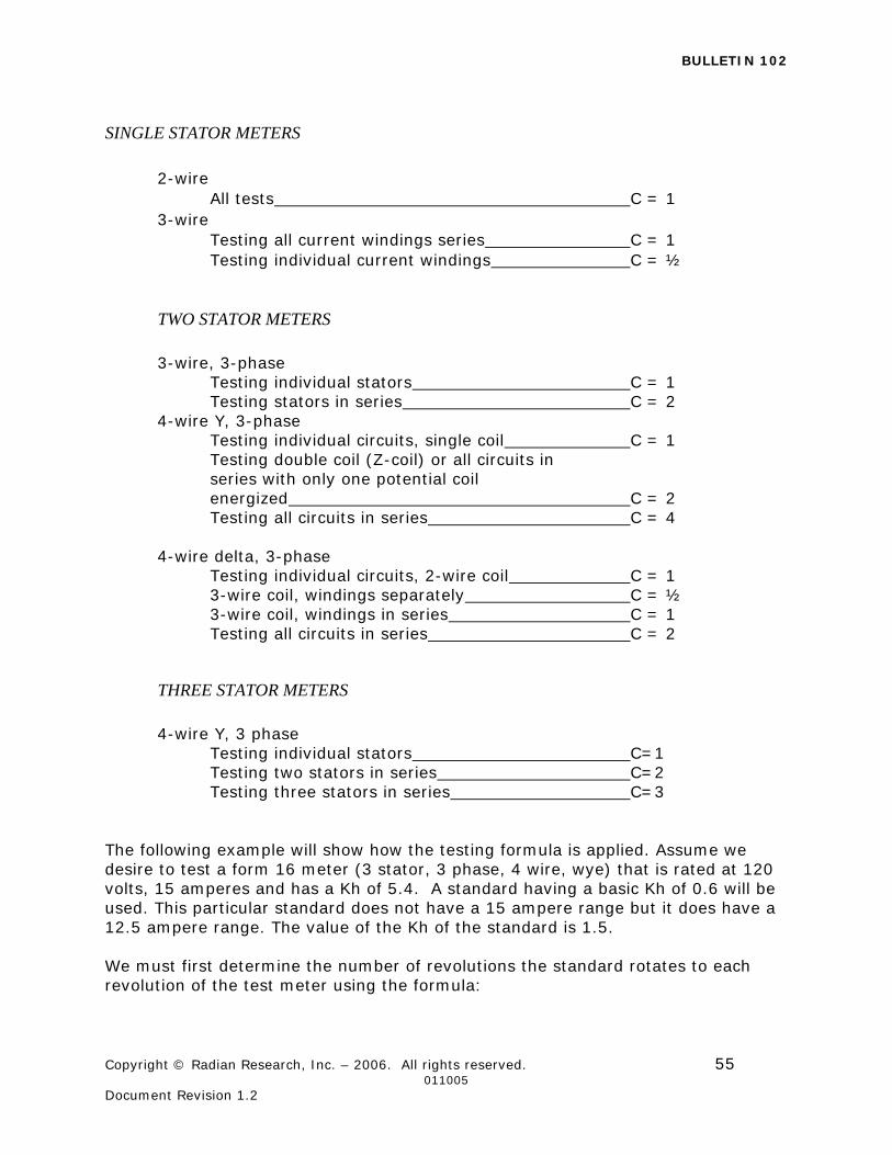
BULLETIN 102
Copyright © Radian Research, Inc. – 2006. All rights reserved. 55 011005 Document Revision 1.2
SINGLE STATOR METERS
2-wire
All tests C = 1 3-wire
Testing all current windings series C = 1 Testing individual current windings C = ½
TWO STATOR METERS
3-wire, 3-phase
Testing individual stators C = 1 Testing stators in series C = 2
4-wire Y, 3-phase Testing individual circuits, single coil C = 1 Testing double coil (Z-coil) or all circuits in series with only one potential coil energized C = 2 Testing all circuits in series C = 4
4-wire delta, 3-phase
Testing individual circuits, 2-wire coil C = 1 3-wire coil, windings separately C = ½ 3-wire coil, windings in series C = 1 Testing all circuits in series C = 2
THREE STATOR METERS
4-wire Y, 3 phase
Testing individual stators C=1 Testing two stators in series C=2 Testing three stators in series C=3
The following example will show how the testing formula is applied. Assume we desire to test a form 16 meter (3 stator, 3 phase, 4 wire, wye) that is rated at 120 volts, 15 amperes and has a Kh of 5.4. A standard having a basic Kh of 0.6 will be used. This particular standard does not have a 15 ampere range but it does have a 12.5 ampere range. The value of the Kh of the standard is 1.5. We must first determine the number of revolutions the standard rotates to each revolution of the test meter using the formula:
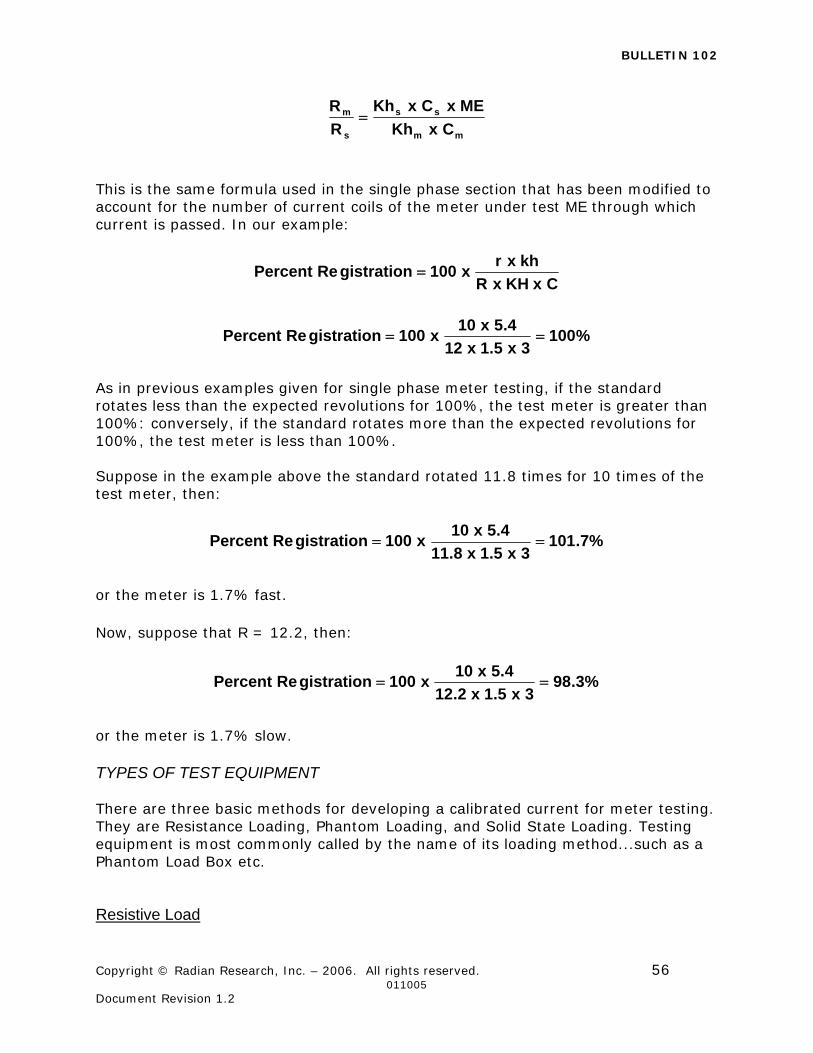
BULLETIN 102
Copyright © Radian Research, Inc. – 2006. All rights reserved. 56 011005 Document Revision 1.2
mm
ss
s
m
CxKh
MExCxKh
R
R
This is the same formula used in the single phase section that has been modified to account for the number of current coils of the meter under test ME through which current is passed. In our example:
CxKHxR
khxrx100gistrationRePercent
%1003x5.1x12
4.5x10x100gistrationRePercent
As in previous examples given for single phase meter testing, if the standard rotates less than the expected revolutions for 100%, the test meter is greater than 100%: conversely, if the standard rotates more than the expected revolutions for 100%, the test meter is less than 100%. Suppose in the example above the standard rotated 11.8 times for 10 times of the test meter, then:
%7.1013x5.1x8.11
4.5x10x100gistrationRePercent
or the meter is 1.7% fast. Now, suppose that R = 12.2, then:
%3.983x5.1x2.12
4.5x10x100gistrationRePercent
or the meter is 1.7% slow. TYPES OF TEST EQUIPMENT There are three basic methods for developing a calibrated current for meter testing. They are Resistance Loading, Phantom Loading, and Solid State Loading. Testing equipment is most commonly called by the name of its loading method...such as a Phantom Load Box etc. Resistive Load
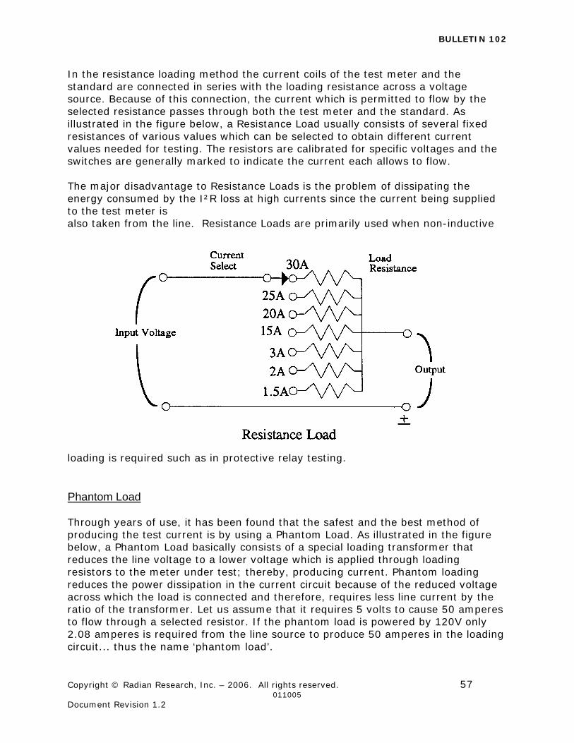
BULLETIN 102
Copyright © Radian Research, Inc. – 2006. All rights reserved. 57 011005 Document Revision 1.2
In the resistance loading method the current coils of the test meter and the standard are connected in series with the loading resistance across a voltage source. Because of this connection, the current which is permitted to flow by the selected resistance passes through both the test meter and the standard. As illustrated in the figure below, a Resistance Load usually consists of several fixed resistances of various values which can be selected to obtain different current values needed for testing. The resistors are calibrated for specific voltages and the switches are generally marked to indicate the current each allows to flow. The major disadvantage to Resistance Loads is the problem of dissipating the energy consumed by the I²R loss at high currents since the current being supplied to the test meter is also taken from the line. Resistance Loads are primarily used when non-inductive
loading is required such as in protective relay testing. Phantom Load Through years of use, it has been found that the safest and the best method of producing the test current is by using a Phantom Load. As illustrated in the figure below, a Phantom Load basically consists of a special loading transformer that reduces the line voltage to a lower voltage which is applied through loading resistors to the meter under test; thereby, producing current. Phantom loading reduces the power dissipation in the current circuit because of the reduced voltage across which the load is connected and therefore, requires less line current by the ratio of the transformer. Let us assume that it requires 5 volts to cause 50 amperes to flow through a selected resistor. If the phantom load is powered by 120V only 2.08 amperes is required from the line source to produce 50 amperes in the loading circuit... thus the name ‘phantom load’.
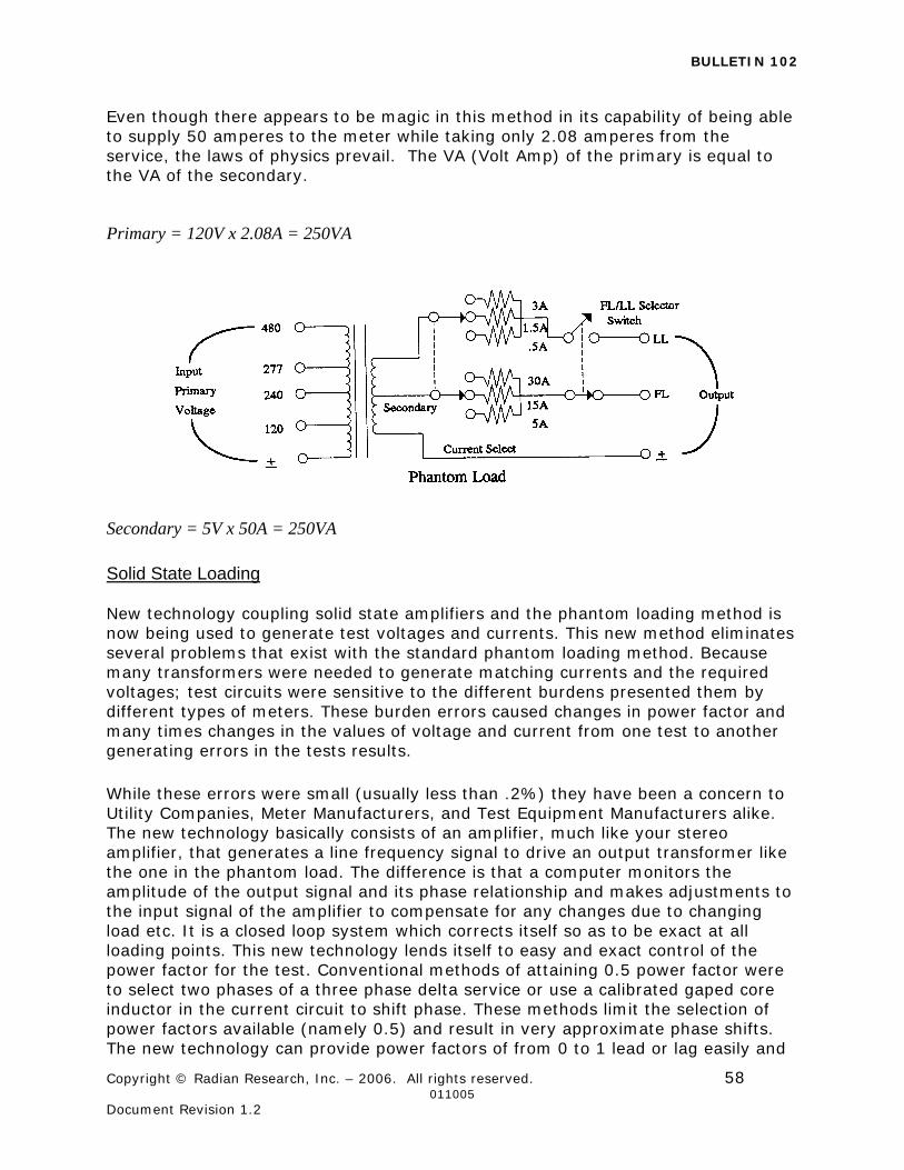
BULLETIN 102
Copyright © Radian Research, Inc. – 2006. All rights reserved. 58 011005 Document Revision 1.2
Even though there appears to be magic in this method in its capability of being able to supply 50 amperes to the meter while taking only 2.08 amperes from the service, the laws of physics prevail. The VA (Volt Amp) of the primary is equal to the VA of the secondary.
Primary = 120V x 2.08A = 250VA
Secondary = 5V x 50A = 250VA
Solid State Loading New technology coupling solid state amplifiers and the phantom loading method is now being used to generate test voltages and currents. This new method eliminates several problems that exist with the standard phantom loading method. Because many transformers were needed to generate matching currents and the required voltages; test circuits were sensitive to the different burdens presented them by different types of meters. These burden errors caused changes in power factor and many times changes in the values of voltage and current from one test to another generating errors in the tests results. While these errors were small (usually less than .2%) they have been a concern to Utility Companies, Meter Manufacturers, and Test Equipment Manufacturers alike. The new technology basically consists of an amplifier, much like your stereo amplifier, that generates a line frequency signal to drive an output transformer like the one in the phantom load. The difference is that a computer monitors the amplitude of the output signal and its phase relationship and makes adjustments to the input signal of the amplifier to compensate for any changes due to changing load etc. It is a closed loop system which corrects itself so as to be exact at all loading points. This new technology lends itself to easy and exact control of the power factor for the test. Conventional methods of attaining 0.5 power factor were to select two phases of a three phase delta service or use a calibrated gaped core inductor in the current circuit to shift phase. These methods limit the selection of power factors available (namely 0.5) and result in very approximate phase shifts. The new technology can provide power factors of from 0 to 1 lead or lag easily and
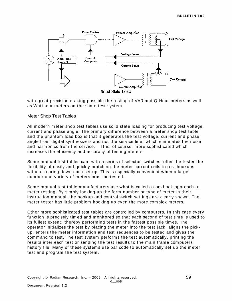
BULLETIN 102
Copyright © Radian Research, Inc. – 2006. All rights reserved. 59 011005 Document Revision 1.2
with great precision making possible the testing of VAR and Q-Hour meters as well as Watthour meters on the same test system. Meter Shop Test Tables All modern meter shop test tables use solid state loading for producing test voltage, current and phase angle. The primary difference between a meter shop test table and the phantom load box is that it generates the test voltage, current and phase angle from digital synthesizers and not the service line; which eliminates the noise and harmonics from the service. It is, of course, more sophisticated which increases the efficiency and accuracy of testing meters. Some manual test tables can, with a series of selector switches, offer the tester the flexibility of easily and quickly matching the meter current coils to test hookups without tearing down each set up. This is especially convenient when a large number and variety of meters must be tested. Some manual test table manufacturers use what is called a cookbook approach to meter testing. By simply looking up the form number or type of meter in their instruction manual, the hookup and control switch settings are clearly shown. The meter tester has little problem hooking up even the more complex meters. Other more sophisticated test tables are controlled by computers. In this case every function is precisely timed and monitored so that each second of test time is used to its fullest extent; thereby performing tests in the fastest possible times. The operator initializes the test by placing the meter into the test jack, aligns the pick-up, enters the meter information and test sequences to be tested and gives the command to test. The test system performs the test automatically, printing the results after each test or sending the test results to the main frame computers history file. Many of these systems use bar code to automatically set up the meter test and program the test system.
BULLETIN 102
Copyright © Radian Research, Inc. – 2006. All rights reserved. 60 011005 Document Revision 1.2
CONTRIBUTING ERRORS TO METER TESTING There are several things that can contribute error when testing watthour meters. Some of the sources of error apply only to the conventional phantom loading method and some apply to both the conventional phantom loading and solid state loading method. The first contributing error to meter testing is resistance in the potential circuit. While a small amount of resistance does not appreciably effect full load unity power factor test, it is of major concern when testing 0.5 power factor contributing as much as .2% for 0.2 ohms of resistance. Resistance is introduced most commonly from dirty contacts on connector jacks, loose or corroded connections and either too long or too small a wire gauge for potential leads. The Phantom Loading method is subject to all of the possible problem areas while the Solid State Loading is subject only to dirty contacts on the connector. Because this method senses the voltage and phase angle at the meter socket, dirty meter blades etc. are outside the control loop and therefore will cause errors in testing.
The second contributing error to meter testing is wave form distortion. Improperly designed transformers, oscillating amplifiers, and voltage regulators coupled with poor transformer designs are the major reasons for wave form distortion. This type of error applies to both phantom and solid state loading methods. This error can be eliminated by choosing a solid state test system that monitors the wave form for distortion and stop the test should distortion appear. The third contributing error to meter testing is timing errors from the photoelectric counter. The relay used to control the standard potential becomes worn and dirty with use which causes unreliable and unpredictable drop-out and pull-in times. Also changing lighting conditions and power supply voltages change the threshold point at which the relay is instructed close and open. Errors produced from the photoelectric counter can contribute as much as ±0.2%. This error applies only to testing systems using switched voltage standards such as the Scientific Columbus SC-10. This error can be eliminated by using only gated display solid state reference standards, such as the Radian RM-10, 11, 15 or Scientific Columbus SC-10V, 20, 30 and Radian Research, Inc. 711 or RM-110 electronic revolutions counters. The fourth contributing error to meter testing is a rotating standard. Rotating standards suffer from a variety of possible problems; among them are dirt, friction, worn bearing, tilt errors, temperature drift, and coasting; all of which contribute errors to meter testing. These errors can be eliminated by using a solid state standard. The fifth contributing error to meter testing is the resolution to which the reference standard is capable of reading. Most rotating standards have resolving abilities of only 1%. In order to get increased resolving ability, multiple revolutions of the standard are necessary. This error is eliminated when the test system uses a solid state standard.
BULLETIN 102
Copyright © Radian Research, Inc. – 2006. All rights reserved. 61 011005 Document Revision 1.2
The sixth contributing error to meter testing is magnetic offset both in the meter under test and the testing equipment’s standard meter and transformers. Magnetic offset is most commonly caused from switching the load on and off at points other than zero on the sine wave. This error is eliminated with test systems that use zero crossing switching or use a ramp function to start and stop the test. The seventh contributing error to meter testing is related to solid state meters. Most solid state meter designs require that the load be applied a few seconds before a measurement of accuracy is taken. This time delay ranges from about 3 to 7 seconds. To eliminate this source of error, energize the MUT with potential and current for at least 10 seconds before beginning a test. The eighth contributing error to meter testing is low service voltage. The problem primarily affects induction (disk type) meters since they typically do not have linear or flat voltage response curves. This condition of low voltage is usually created by the additional load drawn by the phantom load when connected to the PT secondary and can cause test error as much as 15%. This error does not exist when using solid state test devices or when testing self-contained meter installations or transformer-rated installations that do not use PT The last and probably the largest contributing error to meter testing is the human error factor. Improper load adjustments, improper test sequences, improper application of correction factors, improper connections, improper recording of test data, and improper selection of testing parameters are among the most common human errors. These errors apply to any test method and are the most difficult to control. Fully automatic solid state test systems minimize these errors.
TESTING SAFETY Safety should be on the mind of every meter tester. When performing field tests, the voltage levels of the service and the fault current capabilities are very dangerous and should not be dealt with lightly. Safety glasses, hard hats, low voltage insulated gloves, and long sleeve fire retardant protective clothing should be worn at all times when a service connecting device such as a meter socket is exposed. The dangers of testing are increased when the tests involve a transformer rated service. These services contain Current Transformers which reduce the high primary currents to lower currents (usually 5 amperes) so that a electricity meter may be used. The Current Transformer is a device that has a low voltage secondary as long as the secondary connection is a continuos connection. If however, the secondary connection is opened and there is current flowing in the primary, the current transformer becomes a step up voltage transformer and the secondary voltage can rise to many thousands of volts. The high voltage that is present on the open secondary of an energized current transformer generates two great hazards. The first hazard is ELECTRICAL SHOCK TO THE TESTING PERSONNEL. The second hazard is THE BREAKDOWN OF THE CURRENT TRANSFORMER INSULATION resulting in the destruction of the
BULLETIN 102
Copyright © Radian Research, Inc. – 2006. All rights reserved. 62 011005 Document Revision 1.2
current transformer. Both hazards can be avoided provided that the secondary of the current transformer is never opened. The safest current transformer installations for testing are those that have as part of the secondary loop a Test Switch. A Test Switch is a device that will facilitate shunting of the current transformer secondary loop without the danger of opening the circuit. This device provides a make-before-break connection to prevent accidental opening of the current transformer secondary when isolating it from the metering circuit. In addition, the test switch provides for the safe insertion of other instruments in the CT secondary loop such as ammeters using a test switch safety plug sometimes referred to as a duck bill plug. The test switch safety plug, like the knife switches, provides a make-before-brake connection so as to guarantee that the CT secondary is never opened. On installations that do not have a Test Switch included in the current transformer secondary loop, THE SECONDARY TERMINALS OF THE CURRENT TRANSFORMER MUST BE SHORTED BEFORE THE LOOP IS OPENED! The shunt or short connected across the CT secondary should be a BOLT-ON or CAPTURED type of connection. Test clips, or any spring type connection, should never be used for shorting a CT secondary. When the CT secondary has been shorted with a bolt-on connection, the electricity meter may be isolated from the secondary circuit for testing. The CT secondary shunt must remain in place until the electricity meter is again wired back into the CT secondary loop so as to complete the circuit. Do not forget to remove the CT secondary shunt before leaving the service site. Leaving the CT secondary shunt ON will, of course, cause the electricity meter not to register energy for that CT and cause a decrease in the customer billing. PROCEDURE FOR TESTING WATTHOUR METERS In the case of single stator meters there are two adjustments to be made in calibrating a watthour meter; one, the “Full Load” adjustment, which involves changing the drag torque developed by the permanent magnets (drag Magnets), the other, the “Light Load” adjustment which compensates for friction. In single stator meters, the power factor adjustment is made at the factory and can not be easily changed in the field. Multi-stator meters (polyphase), however, have power factor adjustments. Typically there is one FL adjustment for the meter, and one LL and PF adjustment for each electromagnet assembly in a multi-stator meter. To properly adjust a watthour meter, its present accuracy must first be determined. This is known as the “As Found” test. After the percentage registration of the meter has been determined by the ‘as found’ test, the necessary adjustments to the FL, PF and LL adjustments are made to bring the meter within the desired accuracy. The final test made on the meter after adjustments are made is known as the “As 1Left” test, because it is that test made on the accuracy of the meter in the condition in which it was left by the tester.
BULLETIN 102
Copyright © Radian Research, Inc. – 2006. All rights reserved. 63 011005 Document Revision 1.2
The procedures for “As Found” and “As Left” tests are identically the same as far as meter connections and readings are concerned. Because of the different procedures for testing, depending on what type and manufacturer of equipment you are using, only the method for using a field load box will be discussed in this paper. However, the basic testing principles can be applied to any piece of testing equipment. Before using any piece of testing equipment, be sure to always consult the manufacturer’s operation manual for complete and correct operation. Connect the meter under test to the portable load box and to the reference standard in such a way that the potential coil of the meter under test is in parallel with the potential coil of the reference standard. The current coil or coils of the meter under test should be connected in series with the current coil or coils of the reference standard and in series with the current circuit of the portable load. The particular current coil of the reference standard should in every case be one which will easily carry as a minimum at least 50% of the testing current but one where the testing current will never be greater than 150% of the reference standard current tap values. In general, two different reference standard current coils must be used for the FL and LL test when using a ‘tap’ type standard. Apply voltage and current to see that the meter under test (MUT) and the reference standard rotate in the proper direction. In those cases where the testing facility consist of a load box and a reference standard which must be connected to the meter by means of removable leads, it is easily possible to accidentally reverse the polarity on either meter or reference standard. In case of reverse rotation, the following should be done:
1. If both meter and standard rotate backward, interchange either the current potential connections or the current connections of the load box. Note, solid state standards will not run backwards, they simply will not run at all if either the voltage and current is wired backwards. In this case, the meter will rotate backwards and the standard will not operate.
2. If the meter only rotates backward, interchange current feed connections
to the meter. 3. If the reference standard only rotates backward or does not operate at all,
interchange either the potential connections or the current connections of the reference standard.
4. If a solid state standard is used and either the potential or current polarity is reversed, the standard will not run at all. Reversing either the potential or current connections to make the standard run.
In certain phantom load designs such as the RADIAN RESEARCH, INC. 402, 403, 404, 406, 407, 408, 418, 440, 441, 443, 452, 453 and 454 meter test kits, permanent connections between the load box and the reference standard eliminate
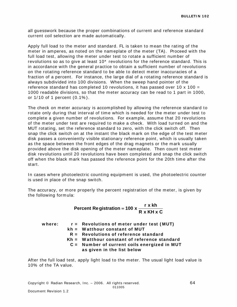
BULLETIN 102
Copyright © Radian Research, Inc. – 2006. All rights reserved. 64 011005 Document Revision 1.2
all guesswork because the proper combinations of current and reference standard current coil selection are made automatically. Apply full load to the meter and standard. FL is taken to mean the rating of the meter in amperes, as noted on the nameplate of the meter (TA). Proceed with the full load test, allowing the meter under test to rotate a sufficient number of revolutions so as to give at least 10* revolutions for the reference standard. This is in accordance with the general practice to obtain a sufficient number of revolutions on the rotating reference standard to be able to detect meter inaccuracies of a fraction of a percent. For instance, the large dial of a rotating reference standard is always subdivided into 100 divisions. When the sweep hand pointer of the reference standard has completed 10 revolutions, it has passed over 10 x 100 = 1000 readable divisions, so that the meter accuracy can be read to 1 part in 1000, or 1/10 of 1 percent (0.1%). The check on meter accuracy is accomplished by allowing the reference standard to rotate only during that interval of time which is needed for the meter under test to complete a given number of revolutions. For example, assume that 20 revolutions of the meter under test are required to make a check. With load turned on and the MUT rotating, set the reference standard to zero, with the click switch off. Then snap the click switch on at the instant the black mark on the edge of the test meter disk passes a conveniently visible stationary reference point, which is usually taken as the space between the front edges of the drag magnets or the mark usually provided above the disk opening of the meter nameplate. Then count test meter disk revolutions until 20 revolutions have been completed and snap the click switch off when the black mark has passed the reference point for the 20th time after the start. In cases where photoelectric counting equipment is used, the photoelectric counter is used in place of the snap switch. The accuracy, or more properly the percent registration of the meter, is given by the following formula:
CxKHxR
khxrx100gistrationRePercent
where: r = Revolutions of meter under test (MUT) kh = Watthour constant of MUT R = Revolutions of reference standard Kh = Watthour constant of reference standard C = Number of current coils energized in MUT as given in the list below
After the full load test, apply light load to the meter. The usual light load value is 10% of the TA value.
BULLETIN 102
Copyright © Radian Research, Inc. – 2006. All rights reserved. 65 011005 Document Revision 1.2
The procedure for obtaining a light load check is exactly the same as the procedure outlined above for a full load check, except that the meter under test now runs at a speed which is only 10% of its speed at full load. So as not to make the time required for testing too long, 2* revolutions of the meter under test will usually suffice. The procedure for obtaining a power factor check is exactly the same as the procedure outlined for a full load check, except the power factor must be set to 0.5 which will cause the meter to run at 50% of its speed at full load. It is important that an “As Found” test be made on the meter without any cleaning or adjustment, since in case of a dispute with a customer it is essential for the power company to know exactly what condition the meter was received in before adjustments were made. For this reason, an “As Found” test is made without touching the meter more than is absolutely necessary in order to make the electrical connections required for test. When the “As Found” test has been completed, worn and defected parts of the meter should be replaced. The procedure for the “As Left” test, both full load, power factor, and light load, is the same as for the “As Found” test, as far as connections and calculations are concerned. The meter is run at full load current (TA), and the necessary adjustment made to the drag magnets to bring the percent registration of the meter at full load within the prescribed limits. After the full load check is completed, the meter is tested on light load and power factor and the necessary adjustments are made to bring the loads within the prescribed limits. The “As Left” test is made with the register in place on the meter. Detailed procedures for meter testing can be found in the Handbook for Electricity Metering, 8th edition, chapter 15; 9th edition, chapter 14; or 10th edition chapter 14. ( * Less revolutions are possible when using solid state reference standards.)
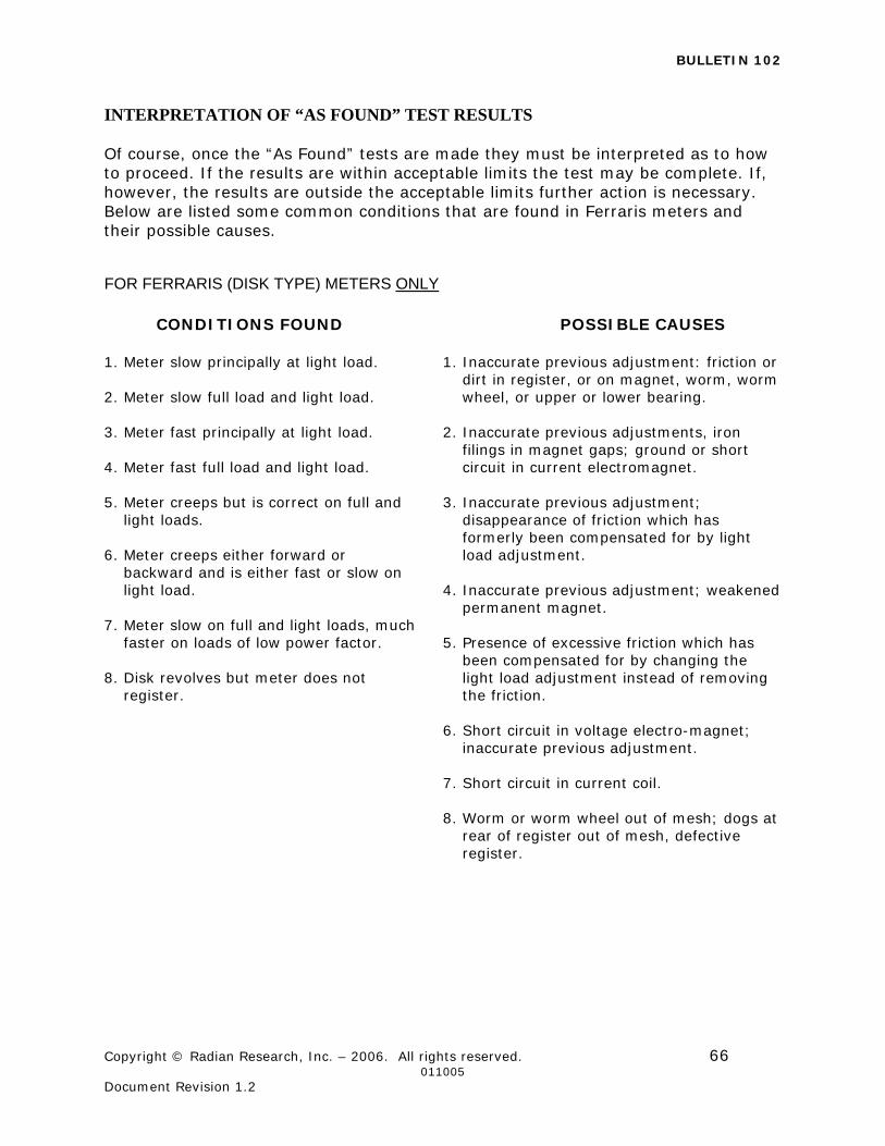
BULLETIN 102
Copyright © Radian Research, Inc. – 2006. All rights reserved. 66 011005 Document Revision 1.2
INTERPRETATION OF “AS FOUND” TEST RESULTS Of course, once the “As Found” tests are made they must be interpreted as to how to proceed. If the results are within acceptable limits the test may be complete. If, however, the results are outside the acceptable limits further action is necessary. Below are listed some common conditions that are found in Ferraris meters and their possible causes.
FOR FERRARIS (DISK TYPE) METERS ONLY
CONDITIONS FOUND POSSIBLE CAUSES 1. Meter slow principally at light load. 2. Meter slow full load and light load. 3. Meter fast principally at light load. 4. Meter fast full load and light load. 5. Meter creeps but is correct on full and
light loads. 6. Meter creeps either forward or
backward and is either fast or slow on light load.
7. Meter slow on full and light loads, much
faster on loads of low power factor. 8. Disk revolves but meter does not
register.
1. Inaccurate previous adjustment: friction or dirt in register, or on magnet, worm, worm wheel, or upper or lower bearing.
2. Inaccurate previous adjustments, iron
filings in magnet gaps; ground or short circuit in current electromagnet.
3. Inaccurate previous adjustment;
disappearance of friction which has formerly been compensated for by light load adjustment.
4. Inaccurate previous adjustment; weakened
permanent magnet. 5. Presence of excessive friction which has
been compensated for by changing the light load adjustment instead of removing the friction.
6. Short circuit in voltage electro-magnet;
inaccurate previous adjustment. 7. Short circuit in current coil. 8. Worm or worm wheel out of mesh; dogs at
rear of register out of mesh, defective register.
Bulletin 102
Copyright © Radian Research, Inc. – 2006. All rights reserved. 67 011005 Document Revision 1.2
METER ADJUSTMENTS IN SOLID STATE METERS Solid state meters are typically not adjustable for calibration by the utility. If a solid state meter test falls outside of acceptable limits, first make sure the meter was put into the test mode. Next the meters programming should be checked for accuracy, particularly the test pulse value. If the programming is ok, the testing equipment should be checked for proper programming and accuracy. If the test equipment is found to be programmed correctly and in calibration; and the meter continues to test out of acceptable limits, it should be returned to the manufacture for repair or replacement. Solid state meters will some day be self adjusting. The meter will control the test via a solid state test bench and will make the necessary calibration adjustments in its own software. METER ADJUSTMENTS IN FERRARIS METERS Full Load Adjustment... The full load adjustment is made by varying the amount of damping flux passing through the disk. In modern meters this is done by a steel screw mounted between the pole faces of the damping magnet which, depending on its position, shunts more or less flux resulting in the speeding or the slowing of the disk. In older meter designs, the magnet position was changed to accomplish the same result. Light Load Adjustment... The light load adjustment is made by varying the amount of light load compensating torque. These adjustments are most commonly screws or wheels which, when turned, shifts a coil so that its position with respect to the element potential coil pole is changed. When this coil is shifted, torque is produced in the meter disk which will turn the disk in the direction of the shift. Over adjustment of the light load may result in “creep” which is a condition where the meter disk rotates with applied voltage and no applied current. Lag or Power Factor Adjustment... The lag adjustments are normally made only in the meter shop. These adjustments establish the flux produced by the potential coil to lag the flux produced by the current coil by exactly 90°. Some older meter designs used a coil with exposed pigtail ends that were soldered so as to lengthen or shorten the overall length of the coil, thereby changing its resistance. Other designs used a lag plate which was adjusted by a screw. In most modern single phase meters the lag adjustment is made by punching a lag plate during the manufacturer’s testing. This type cannot be easily adjusted in the field. Element Balance... A polyphase meter is actually two or three single phase meters sharing the same disk. The result shown by the register of a polyphase meter is, of course, the polyphase watthours or the sum of the individual phase energies. It is therefore necessary to make certain that all phase elements are calibrated correctly. This is accomplished by testing and calibrating each element of a polyphase meter so that the individual elements are as equal as possible for each load point.
Bulletin 102
Copyright © Radian Research, Inc. – 2006. All rights reserved. 68 011005 Document Revision 1.2
After the elements are balanced, a series element test is made to verify the summing of the watthour meter. A more complete description of these adjustments can be found in the Handbook for Electricity Metering, 8th edition or 9th edition, chapter 7. MECHANICAL REGISTER INSPECTION The register is the counting or totalizing device which ultimately translates the revolutions of the meter into kilowatt-hour readings. It is important for the register to function properly as for the meter to rotate at the proper speed. The following points concerning the register should be noted: Friction... The projecting dog or gear which meshes with the meter disk drive should be spun around rapidly with one finger. It should move smoothly and easily. Meshing... With the register in place on the meter, there should be a slight amount of “wiggle” or backlash between the first register gear and the worm or pinion on the meter disk shaft, so that there will be no friction due to binding. Register Ratio... All registers are marked with a number which is known as the “register ratio”. This ratio is the speed reduction between the first or meshing gear of the register and the units dial of the register. To actually check the ratio of the gearing within a register, special laboratory facilities are required. The tester in the field must necessarily assume that the register ratio has the value which is marked on the register, and it is the function of the tester to see that the value agrees with the rated capacity of the meter. RECORDING TEST RESULTS After the meter has been cleaned, calibrated, and the register inspected, an “as left” test should be run. The result should be recorded together with the serial number, date tested, tester, test equipment number, and in many cases the “as found” data for the meter history file. In the more sophisticated testing equipment this may be done automatically. In other cases the procedure outlined by your meter shop foreman should be used. The meter cover should now be replaced and sealed so that the meter is ready for installation on a customer’s service.