Embed Size (px)
Citation preview

www.rosemount-tg.com
Technical Description501026En, Ed. 4, Rev AFebruary 2012
Radar Level Gauge


Technical Description501026En, Ed. 4, Rev AFebruary 2012 TankRadar Pro
3
Contents
System overview ________________________________________________ 5
Features _______________________________________________________ 6
Measurement principle ___________________________________________ 6
Applications ____________________________________________________ 7
Select the right Pro gauge ________________________________________ 8Transmitter Head versions ________________________________________________8Software modules _______________________________________________________8
Antenna versions ________________________________________________ 9Cone antenna __________________________________________________________9Parabolic antenna ______________________________________________________10Still-pipe Array antenna __________________________________________________ 11Process seal antenna ___________________________________________________12
Flanges _______________________________________________________ 12
Measuring range _______________________________________________ 13
System integration _____________________________________________ 144-20 mA HART systems _________________________________________________14TRL2 fieldbus systems __________________________________________________15
Mechanical mounting ___________________________________________ 16Free propagation _______________________________________________________16Pipe installation ________________________________________________________17
Electrical connections ___________________________________________ 17
Specification __________________________________________________ 18
Product certificates _____________________________________________ 21
Ordering information ____________________________________________ 23Transmitter Head ______________________________________________________23

TankRadar ProTechnical Description
501026En, Ed. 4, Rev AFebruary 2012
4
Copyright © February 2012 by Rosemount Tank Radar AB.
Technical data is subject to change without prior notice. Rosemount Tank Radar AB accepts no responsibility for any errors that may appear in this description.
Viton, and Kalrez are trademarks of Du Pont Performance Elastomers. Hastelloy is a trademark of Haynes International. Monel is a trademark of International Nickel Co.
HART is a trademark of the HART Communication Foundation
DeltaV is a trademark of Emerson Process Management group of companies.
All other marks are the property of their respective owners.
Antennas _____________________________________________________________24Cone antenna ______________________________________________________24Cone antenna, extended _____________________________________________25Cone antenna with integrated purging ___________________________________26Parabolic antenna ___________________________________________________27Still-pipe array antenna _______________________________________________271- and 2-in. still-pipe antennas _________________________________________28Process seal antenna ________________________________________________29Model Code Example ________________________________________________29
Wireless _____________________________________________________________30Smart Wireless THUM™ Adapter _______________________________________30Smart Wireless Tank Gauging Options ___________________________________30
Technical Description501026En, Ed. 4, Rev AFebruary 2012 TankRadar Pro
5
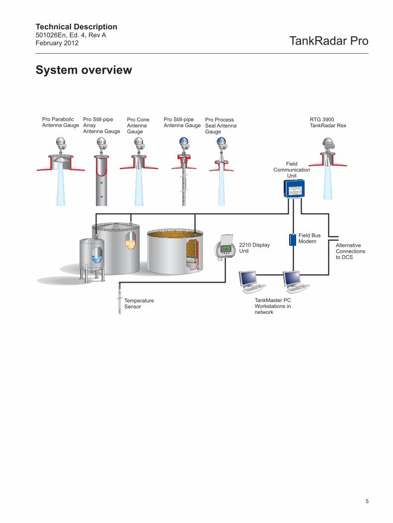
System overview
Temperature Sensor
Pro Parabolic Antenna Gauge
Pro Still-pipe ArrayAntenna Gauge
Pro Cone Antenna Gauge
RTG 3900 TankRadar Rex
Field Communication
Unit
2210 Display Unit
Field Bus Modem
TankMaster PC Workstations in network
Alternative Connections to DCS
Pro Still-pipe Antenna Gauge
Pro Process Seal Antenna Gauge

TankRadar ProTechnical Description
501026En, Ed. 4, Rev AFebruary 2012
TankRadar Pro with its flexible configuration is suitable for both stand-alone applications and large-scale plant installations with various tank types.
The FMCW method is based on a radar sweep with continuous changes in frequency.
f1 f0
fmax
f1
f0
fmin
Frequency (GHz) Transmitted
Reflected
Time
∆ f
t0 t1
∆ t
∆ f ~ ∆ t ~ ∆d
d
6
• Multi-purpose radar level gauge
• No moving parts and no contact with the liquid
• No maintenance
• Highest reliability
• Easy installation
• High accuracy
• Handles difficult tank conditions due to ultra-high sensitivity and unique signal processing features
• High flexibility with interchangeable Transmitter Heads and antennas
• A wide array of antennas and versions for best performance in all applications
• Interactive setup with Windows based PC software or via display unit
• Analog 4-20 mA superimposed with HART , and digital Profibus DP, TRL2, or RS485 fieldbus outputs
Measurement principle The level of the liquid (or solid) is measured by radar signals transmitted from the antenna at the tank top. After the radar signal is reflected by the liquid surface the echo is picked up by the antenna. As the signal is varying in frequency the echo has a slightly different frequency compared to the signal transmitted at that moment. The difference in frequency is proportional to the distance to the liquid, and can be accurately calculated. This method is called FMCW (Frequency Modulated Continuous Wave) and is used in all high performance radar gauges.
TankRadar Pro uses the 10 GHz frequency band to get optimum balance between beamwidth and sensitivity to antenna contamination.
Features

Technical Description501026En, Ed. 4, Rev AFebruary 2012 TankRadar Pro
7
TankRadar Pro uses state-of-the art microwave technology to get highest reliability and precision. It measures the level of liquids, slurries as well as many solids. The gauge operates in a wide range of temperatures, pressures, vapor gas mixtures and various process conditions.
The applications include:
• Storage tanks at refineries and tank terminals
• LPG storage
• Power plants
• Chemical & petrochemical industry
• Pharmaceutical
• Food and beverage
• Water and sewage treatment
• Hydroelectric power generation and dams
• Cement, powder, wood chips and other solid material applications
Applications in tanks with agitators require a radar gauge with TankRadar Pro’s high sensitivity and advanced signal processing to separate the measuring signal from noise created by disturbances.
Still-pipe or bridle mounting is recommended for LPG applications, where the surface sometimes is boiling, and for some extremely turbulent conditions. The pipe reduces foam and turbulence and also increases surface reflection.
TankRadar Pro parabola and cone versions provide free propagation, high accuracy level measurement in storage tanks.
Solid materials, like cement, often give extremely small radar reflections, requiring the most sensitive antenna, the 20” parabolic.
Applications

TankRadar ProTechnical Description
501026En, Ed. 4, Rev AFebruary 2012
Antenna
Tank connection
Weather protection
Electronic housing
Display unit
Junction box Ex (e)
Cable glands
Junction box Ex (i)
8
A TankRadar Pro gauge consists of a Transmitter Head and a tank connection including antenna. The Transmitter Head, as well as the electronics inside, is interchangeable without opening the tank.
Transmitter Head versionsThe Transmitter Head is available in four basic versions:
• LiteIntended for applications in non-hazardous areas only. Suitable for tanks without internal structures and agitators, e.g. certain storage tanks, water, dam applications etc. The Lite version has FFT calculations enabled providing an instrument accuracy of ± 10 mm (± 0.4 in.). Echofixer, FHAST™ and MET™ are available as options.
• StandardFor hazardous applications in most tanks (also spheri- cal or bullet tanks, and tanks with internal structures). The Standard version includes the Echofixer software which more accurately than standard FFT maps all microwave interference sources. The Standard instrument accuracy is ± 10 mm (± 0.4 in.) which can be improved to ± 5 mm (± 0.2 in.) using the optional FHAST™ software module.
• GoldGold is the most advanced version for difficult applications in tanks with agitators, heating coils and other disturbances. It includes the Echofixer software, FHAST™ software for increased accuracy plus MET™ software for further increased disturbance echo handling. Instrument accuracy is ± 5 mm (± 0.2 in.).
• PlatinumFor high accuracy tank gauging applications, Platinum is the best TankRadar Pro choice. It includes the FHAST™ software and selected hardware for maximum performance. Instrument accuracy is ± 3 mm (± 0.12 in.) for parabolic, still-pipe array and 8-in. cone antennas.
Volume calculation for symmetrical tanks is included in all versions. Strapping table for non-symmetrical tanks is available as an option.
Software modulesVarious options make it possible to optimize the gauge for different applications:
• Fast Fourier Transformation (FFT)Fast Fourier Transformation is a signal processing technique used to map the echo structure of the tank.
• EchofixerA software module that makes it possible to measure on the surface in spite of strong disturbance echoes from mechanical structures such as agitators and baffles.
• Fast High Accuracy Signal Technology (FHAST™)A module that improves the efficiency of the signal processing by limiting the region to be analyzed around the surface. This results in an improved accuracy of ± 5 mm (± 0.2 in.).
• Multiple Echo Tracking (MET™)Improves the resolution and accuracy in echo disturbed regions and close to the tank bottom. Continuous measurement on multiple disturbing echoes facilitates identification of the actual surface echo.
All software options are possible to upgrade in the field without any changes in electronics. Upgrades are made by entering a new start code in the gauge and can be done on a temporary basis for trial purposes.Software modules in available Pro versions
Explosion approval
FFT FHAST™Increased accuracy
Echofixer Disturbance
echo handling
MET™Improved resolution
Lite - X Option Option Option
Standard X X Option X Option
Gold X X X X X
Platinum X X X Option -
Select the right Pro gauge

Technical Description501026En, Ed. 4, Rev AFebruary 2012 TankRadar Pro
4002001000 300-40
605550
40
30
20
10
-1
0
5
798
-15
145
73
0
75239221232 570-40
1
1
2
2
The relation between temperature and maximum pressure for cone antennas.
The thin antenna plate prevents the flange from exposure to the tank environment.
2 in. : 70 (2.76) 3 in. : 95 (3.74) 4 in. : 150 (5.91) 6 in. : 260 (10.24) 8 in. : 370 (14.57)
2 in. : 56 (2.20) 3 in. : 70 (2.76) 4 in. : 93 (3.66) 6 in. : 141 (5.55) 8 in. : 189 (7.44)
200 (7.87)
mm (inches)
400(15.75)
Temperature (°F)
Temperature (°C)
Pre
ssur
e (b
ar)
Pre
ssur
e (p
sig)
QuartzPTFE
2-in. Still-pipe Antenna
TankRadar Pro can be equipped with different antennas to fulfill various requirements. The tank connection, including antenna, is the only part exposed to the tank atmosphere. The cone antenna is most commonly used. When selecting antenna dimension, it is generally recommended to use as large antenna diameter as possible.
Cone antennaThe cone antenna is suitable for liquid applications. It can be used for both free propagation and still-pipe mounted installations. Thanks to the unique flange clamp solution the existing tank flange can be used as tank connection. The gauge can also be delivered with flange included.
• Standard cone antennas for 3-, 4-, 6- and 8-in. tank openings. The 3-, 4- and 6-in. cones can be extended to fit long tank nozzles. See pages 23-30, “Ordering Information”, for standard flange options
• A 1- and 2-in. version is available together with a still-pipe solution
• For larger pipes, use the still-pipe array antennas
• Materials exposed to the tank atmosphere:Sealing in PTFE or quartzAntenna in stainless steel, Hastelloy C-22Titanium gr. 2, Monel 400 or TantalumO-ring in Viton fluoroelastomer or Kalrez
perfluoroelastomer
• Accuracy up to ± 5 mm (± 0.2 in.) using the FHAST™ software option
• Accuracy with 8-in. cone up to ± 3 mm (± 0.12 in.) using the Platinum version
See page 17 for description of still-pipe installations. For pressure and temperature restrictions depending on flange and O-ring selection, see page 20.
Antenna versions
9

TankRadar ProTechnical Description
501026En, Ed. 4, Rev AFebruary 2012
23020050 100 1500-40
445392122 212 30232-40
10
+0.20.5
0.5-0.2
145
0+2.9
-2.90
5 73
1
1
1
2
2
mm (inches)
440(17.32)
162(6.4)
445 (17.52)
200 (7.87)
Temperature (°F)
Temperature (°C)
Pre
ssur
e (b
ar)
Pre
ssur
e (p
sig)
WeldedClamped
10
Parabolic antennaThe parabolic antenna is suitable for both liquid and solid applications. As it has the largest diameter it has the most narrow radar beam and can be used for extremely long measuring distances.
The parabolic is also the antenna type most insensitive to contamination. It can be used in applications with severe antenna condensation like asphalt and liquid sulphur.
Two versions are available: the very easily installed version with clamped mounting of flanges with a 96 mm (3.78-in.) diameter hole in flange (low pressures) and a welded version (high pressures).
• Suitable in all tanks with 450 mm (18 in.) or larger openings
• Exposed parts in tank: Stainless steel and FEP/PTFE fluoropolymer
• Best installed accuracy for inventory applications
• Highest antenna gain
• Withstands heavy contamination
• Flexible PTFE protective cover available for dusty applications
• Suitable for long range measurement up to 100 m (330 ft)
• ± 3 mm (± 0.1 in.) accuracy for platinum version
The relation between temperature and maximum pressure for parabolic antennas.
Parabolic antenna welded to tank opening.

Technical Description501026En, Ed. 4, Rev AFebruary 2012 TankRadar Pro
0 20 40 60 80 100
104 140 176 212
120-40
32 68 248-40
0 0
3.6
7.2
14.5
29
0.25
0.50
0.75
1.00
1.25
1.50
1.75
2.00
1
123
2
3
Pre
ssur
e (p
sig)
200 (7.87)
mm (inches)
400(15.75)
Pro Still-pipe Array Antenna, fixed version.
Pro Still-pipe Array Antenna, hinged-lid version with design that enables hand-dipping.
Hinged Hatch 10 & 12 in.
Temperature (°C)
Pre
ssur
e (b
ar)
Hinged Hatch 5,6 and 8 in.Fixed
Temperature (°F)
11
Still-pipe Array antennaThe Still-pipe Array Antenna with its small-sized antenna is designed for mounting on existing still-pipes. Typical applications are crude oil tanks with floating roofs and gasoline/product tanks with or without inner floating roofs.
The gauge uses a unique patented Low Loss Mode to transmit the radar waves in the center of the pipe. This virtually eliminates degradation of the accuracy due to rust and product deposits inside the pipe.
The Still-pipe Array Antenna is available in two models, the fixed and the hinged-lid version.
The still-pipe must be vertical within 0.5° (0.2 m over 20 m) to obtain highest measurement accuracy.
• Suitable for mounting on existing still-pipes
• Small-sized antenna for 5-, 6-, 8-, 10- or 12-in. still-pipes
• Exposed parts in tank:Antenna in Polyphenylensulfid (PPS)Sealing in PTFEO-ring in FluorosiliconeFlange in Acid Proof Steel EN 1.4404(AISI 316L)
• ± 3 mm (± 0.1 in.) accuracy
The relation between temperature and maximum pressure for array antennas.
TankRadar ProTechnical Description
501026En, Ed. 4, Rev AFebruary 2012
12
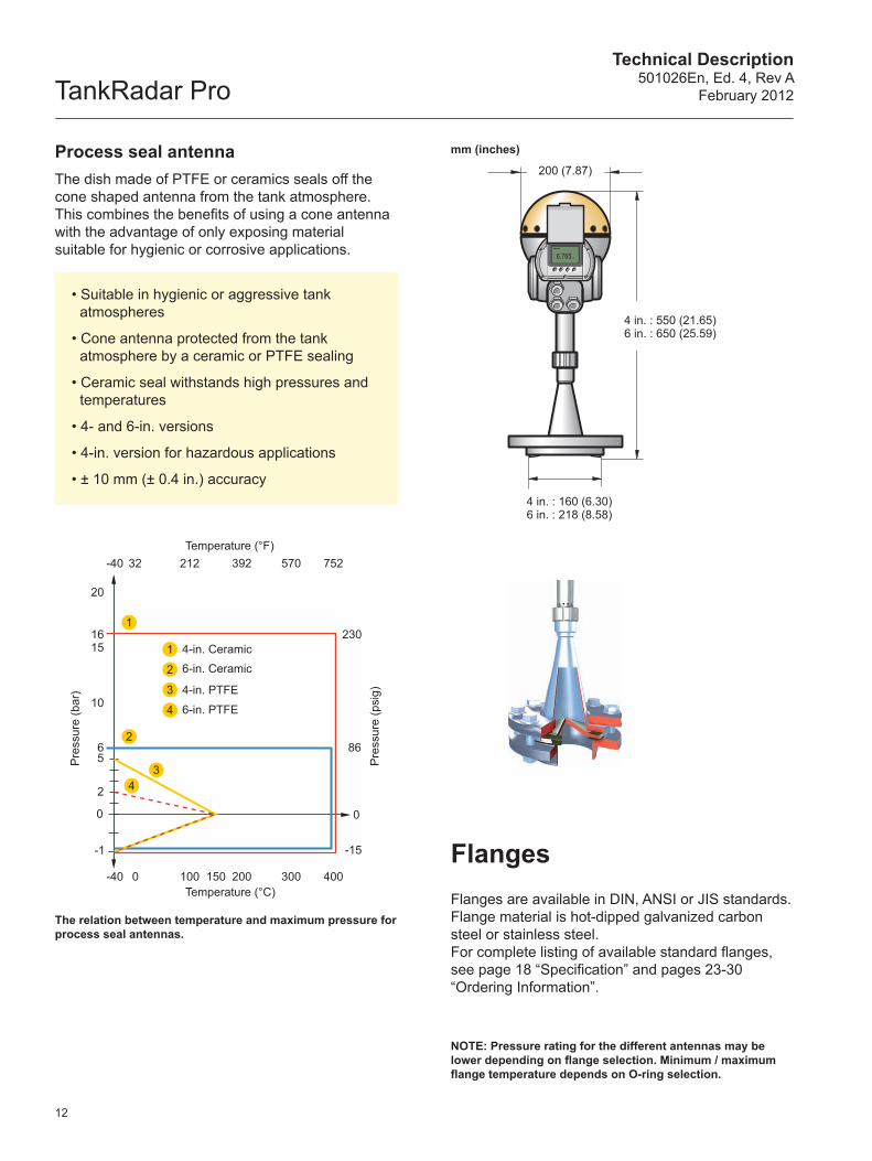
Flanges are available in DIN, ANSI or JIS standards. Flange material is hot-dipped galvanized carbon steel or stainless steel. For complete listing of available standard flanges, see page 18 “Specification” and pages 23-30 “Ordering Information”.
Flanges
4 in. : 550 (21.65) 6 in. : 650 (25.59)
200 (7.87)
mm (inches)
4 in. : 160 (6.30) 6 in. : 218 (8.58)
Process seal antennaThe dish made of PTFE or ceramics seals off the cone shaped antenna from the tank atmosphere. This combines the benefits of using a cone antenna with the advantage of only exposing material suitable for hygienic or corrosive applications.
• Suitable in hygienic or aggressive tank atmospheres
• Cone antenna protected from the tank atmosphere by a ceramic or PTFE sealing
• Ceramic seal withstands high pressures and temperatures
• 4- and 6-in. versions
• 4-in. version for hazardous applications
• ± 10 mm (± 0.4 in.) accuracy
400200100 1500 300-40
20
-1
0
-15
0
75239221232 570-40
15
10
56 86
16 230
2
1
1
2
3
4
2
34
Temperature (°F)
Temperature (°C)
Pre
ssur
e (b
ar)
Pre
ssur
e (p
sig)
4-in. Ceramic6-in. Ceramic
4-in. PTFE
6-in. PTFE
The relation between temperature and maximum pressure for process seal antennas.
NOTE: Pressure rating for the different antennas may be lower depending on flange selection. Minimum / maximum flange temperature depends on O-ring selection.

Technical Description501026En, Ed. 4, Rev AFebruary 2012 TankRadar Pro
13
0
10
20
30
40
50
60
0
10
20
30
40
50
60
0
10
20
30
40
50
60
0
10
20
30
40
50
60
0
10
20
30
40
50
60
a b c a b c a b c a b c a b c
0
10
20
30
40
50
0
10
20
30
40
50
0
10
20
30
40
50
0
10
20
30
40
50
0
10
20
30
40
50
a b c a b c a b c a b c a b c
0
10
20
30
40
50
0
10
20
30
40
50
0
10
20
30
40
50
0
10
20
30
40
50
0
10
20
30
40
50
a b c a b c a b c a b c a b c
3-in. Cone 4-in. Cone 6-in. Cone 8-in. Cone Parabolic(m)
(m)
5-, 6- and 8-in.Array Antenna
10-12-in.Array Antenna
1-in. Still-pipeAntenna
2-in. Still-pipeAntenna
3-6-in. Cone Antenna in existing still-pipe
(m)
The diagrams below show how the measuring range is influenced by the antenna type, dielectric constant of the liquid (εr) and the process conditions. For optimum performance the maximum measuring distance should be kept within the range indicated with darker colour in the diagrams. To increase the measuring range further in turbulent tanks, a still-pipe can be used.
Measuring range in tanks with calm surfaces.
Measuring range in gently stirred tanks.
Measuring range in still-pipe tanks.
Measuring range
a: Oil, petrochemicals, gasoline and other hydrocarbons (εr=1.9-4.0).
b: Alcohols, concentrated acids, organic solvents, oil/water mixtures and acetone (εr=4.0-10).
c: Conductive liquids, e.g. water based solutions, dilute acids and alkalis (εr > 10).
For still-pipe mounted Pro gauges the typical measuring range is 35-50 m (115-160 ft) also in turbulent tanks with liquids having εr less than 1.9.
NOTE: • For liquids with εr smaller than 1.9, such as liquefied gas, an 8-in. or bigger antenna is recommended for free propagation measurements. In this case, the typical measuring range is 15 m (50 ft).• The measuring range for 4- and 6-in. process seal antennas equals about 60% of that for 4- and 6-in. cone antennas.• For array antennas, the measuring range depends on still-pipe slot size.
• The values below are valid for clean antennas.• Max. product level should be kept 20 mm (0.8 in.) from the antenna end.
3-in. Cone 4-in. Cone 6-in. Cone 8-in. Cone Parabolic

TankRadar ProTechnical Description
501026En, Ed. 4, Rev AFebruary 2012
14
Control System
PC with TankMaster software
Modem
Handheld Communicator
Remote display
Alarm Relay Unit
4-20 mA/HART
Temperature sensor
TankRadar Pro can be equipped with a number of different output alternatives such as 4-20 mA HART, Profibus DP, the Rosemount Modbus based TRL2 field bus or RS485. Any or multiple of the calculated values such as level, volume, average temperature or signal strength can be assigned to the signal output.
Data are displayed on the optional 2210 Display Unit mounted on the gauge or separately. Via the remotely mounted display, up to six temperature sensors can be connected.
TankRadar Pro is easily configurable on the 4-key display keyboard or via a PC using the windows based TankMaster Winsetup software package.
4-20 mA HART systemsThe 4-20 mA HART analog outputs are either passive for connection to powered cables or active providing signal power for external display units etc. The analog outputs can also be specified to be intrinsically safe. Configuration can also be done from a Rosemount AMS™ system or a 375/475 Handheld Communicator.
The intrinsically safe 2210 Display Unit shows level (m or ft) and temperature (ºC or ºF), and it can be used for gauge configuration.
System integration

Technical Description501026En, Ed. 4, Rev AFebruary 2012 TankRadar Pro
15
Group Buses
PC with TankMaster software
Field Buses
Field Communication Unit
TankRadar Rex
Tem
pera
ture
In
put
Safe Area Hazardous Area
TankRadar Pro
Tem
pera
utur
e S
enso
r
Display Unit
TRL2 fieldbus systemsWhen using the digital TRL2 field bus outputs, up to 12-15 gauges can be connected to each two-wire field bus, maintaining a high data updating speed. Each field bus is connected to a Field Communication Unit (FCU) that handles up to four field buses with data from maximum 32 tanks. Several FCU's can be installed to handle a large number of tanks. From the FCU, data can be transmitted on RS232/485 or TRL2 bus formats to host computers (DCS, PC or PLC). Pro gauges with TRL2 bus output can also be connected to the TankMaster operator software providing an OPC server that can be linked to the plant network.

TankRadar ProTechnical Description
501026En, Ed. 4, Rev AFebruary 2012
16
Minimum distance:0.6 m (2.0 ft)
10 mm (0.4 in.) or more
Half power beam width
Beam angle
5m
10m
15m
20m
Dis
tanc
e
The TankRadar Pro gauge is easily carried to the tank top and mounted on a suitable nozzle or pipe.
Free propagationThe gauge should be installed as follows:
• Antenna oriented perpendicular to a horizontal surface
• The gauge should be mounted with as few disturbing objects as possible within the beam angle
• Filling inlets creating turbulence should preferably be kept at a distance
• Choose as large antenna diameter as possible. A larger receiving area concentrates the radar beam and ensures maximum antenna gain. Increased antenna gain means greater margin for weak surface echoes
• The cone antenna may be inclined 1-2° towards the center of the tank to increase the accuracy (applicable for tanks higher than 10 m)
Beam Diameter and Beam Angle
Distance, m (ft) Antenna type
3-in. Cone 4-in. Cone / 4-in. Process Seal
6-in. Cone / 6-in. Process Seal
8-in. Cone Parabolic
Beam angle
25° 21° 18° 15° 10°
5 (16) 2.2 (7.2) 1.9 (6.2) 1.6 (5.2) 1.3 (4.3) 0.9 (3.0)
10 (33) 4.4 (14) 3.7 (12) 3.1 (10) 2.6 (8.5) 1.7 (5.6)
15 (49) 6.7 (22) 5.6 (18) 4.7 (15) 3.9 (13) 2.6 (8.5)
20 (66) 8.9 (29) 7.4 (24) 6.3 (21) 5.3 (17) 3.5 (11)
The flat tank wall can be located within the antenna beam angle, as long as there is a minimum distance from the gauge to the tank wall, see picture above.
An extended cone (picture on the right) can be used for long nozzles.
The standard length of the extended cone is 500 mm (20 in.) for 3-, 4- or 6-in. cone antennas. Longer cones are available on request.
For best measurement performance the nozzle height should be shorter than the antenna.
Mechanical mounting
Beam Diameter and Beam Angle for TankRadar Pro antennas.
Cone Antenna Extension
Best practice for mechanical mounting of free propagation radar level gauge.

Technical Description501026En, Ed. 4, Rev AFebruary 2012 TankRadar Pro
17
Deflection plate
IS Gnd
DP DADP+4-20 mA-4-20 mA+4-20 mA HART-4-20 mA HART+
X2123456
4-20 mA-4-20 mA+
L/L2/-
X21234
N/L1/+
4-20 mA HART+ /Profibus DP/TRL2 bus 4-20 mA HART- /Profibus DP/TRL2 bus
X1
4321
7 DP DB
Alternative 1 Intrinsically Safe (EEx i)
Display Panel
Secondary output
Primary output
Alternative 2 Non Intrinsically Safe (EEx e)
Secondary output
Not used
Non Intrinsically Safe (EEx e)
Primary output
Power supply
Pipe installationStill-pipe installation is particularly suitable for applications with highly turbulent liquids or liquids with very low εr giving weak radar reflections, such as LPG. 2-, 3-, 4- and 6-in cone antennas can be mounted in existing still-pipes.
Used pipes must generally be clean inside, without irregularities, rust or excessive holes.
Also available is a 1-in. still-pipe and antenna assembly with a maximum range of 3 m (10 ft). The 1- and 2-in. still-pipe gauges are suitable for clean liquids only and can be delivered complete with still-pipe, deflection plate and fittings without any need for welding. It is also possible to use the Still-pipe Array antenna for measurement inside an existing still-pipe. This antenna is available in 6-, 8-, 10- and 12-in., fixed and hinged-hatch designs.
Consult Emerson Process Management / Rosemount Tank Gauging or an authorized distributor for installation advice.
Electrical connections The Transmitter Head has two separate junction boxes. One is for a non-intrinsically safe primary signal output and power supply cables. The other is normally used for intrinsically safe (IS) HART/analog outputs or optionally for a non-IS analog output.
Outputs can be either active or passive depending on required options.
Cables are twisted and shielded pairs, minimum 0.5 mm2 (AWG 20), ½-in. NPT (threaded) for cable glands or male conduit fittings.
For complete installation instructions, see the Reference Manual for TankRadar Pro (306010E).
TankRadar Pro measures level in 1- to 12-in. still-pipes.

TankRadar ProTechnical Description
501026En, Ed. 4, Rev AFebruary 2012
18
SpecificationGeneral
Product designation TankRadar Pro: Lite, Standard, Gold or PlatinumOperating principle 10 GHz FMCW radarBeam angle See page 16Internal calibration Integrated digital reference for automatic compensation of radar sweepSignal processing Digital signal processing using FFT, FHAST™, MET™ and Echofixer Temperature measurement 1-3 spot elements, PT100 or CU100, or 6 spot elements with common return.
Input accuracy ± 0.5 °C ( ± 0.9 °F)
Display / Configuration
Display (factory mounted on gauge) • 6-digit graphical LCD display, 128 x 64 pixels• For display and configuration • 4 control soft-keys• 7 text lines with 16 characters/line • Weather/dirt protection cover. Protection class IP67
Display (mounted separately) Same as above, mounted in separate enclosure, Protection class IP67 Max cable length, display - radar gauge: 100 m (330 ft) Cable type: 4 wire shielded instrument cable, min 0.5 mm², (AWG 20) Optional: Temperature measurement 1-3 spot elements PT100 or CU100 (see above)
HART device 375/475 handheld communicator Rosemount Asset Management Solutions software (AMS™)
PC/remote configuration TankMaster WinSetup software
Mechanical
Antennas Cone, Parabolic, Still-pipe Array, and Process Seal antennasAntenna material exposed to tank atmosphere
Cone Antenna (PTFE sealing)
Antenna Material, alt 1: Stainless Steel 316L, alt 2: Hastelloy C-22, alt 3: Tantalum, alt 4: Monel 400 O-rings: Viton fluoroelastomer or Kalrez perfluoroelastomer Sealing: PTFE fluoropolymer
Cone Antenna (Quartz sealing)
Antenna Material, alt 1: Stainless Steel 316L, alt 2: Hastelloy C-22, alt 3: Tantalum, alt 4: Monel 400O-rings: Viton fluoroelastomer or Kalrez perfluoroelastomer Sealing: Quartz
Parabolic Antenna Stainless Steel 316L, FEP/PTFE fluoropolymerProcess Seal Antenna PTFE fluoropolymer or Al2O3 (Aluminium oxide)1- and 2 in. Still-pipe Antennas
Antenna Material: Stainless Steel 316L O-rings: Viton fluoroelastomer or Kalrez perfluoroelastomer Sealing: PTFE fluoropolymer or Quartz
Still-pipe Array Antenna Antenna Material: Polyphenylensulfid (PPS) O-ring: FluorosiliconeSealing: PTFE fluoropolymer
Antenna dimensions See pages 9-12Antenna extension Dimensions See page 16
Material Extended cone antennas available in Stainless steel 316LFlushing connection 1/2-in. NPTHousing/enclosure Permanent mould cast aluminium, chromed and 120 μm powder paintedFlanges DIN, ANSI and JIS standard,
Material: Stainless Steel A182 Gr. F 316L and EN 10222-5-1.4404Weight, excl. flange Approximately 8 kg (18 lbs), depending on antenna selectionHeight above flange 400 mm (15 in.)

Technical Description501026En, Ed. 4, Rev AFebruary 2012 TankRadar Pro
19
Electrical
Power supply Ultra-wide 24–240 V DC or AC 0-60 HzPower consumption Maximum 10 W, nominal 5 WOutputs Primary output
(for level, volume etc)Alt. 1: HART + 4–20 mA current loop (IS option) Alt. 2: TRL2 Bus (FSK with Modbus protocol) Alt. 3: Profibus DP
Secondary output (Optional, for volume, signal quality, temperature etc.)
Analog 4–20 mA current loop, active or passive. Optional: IS version.
Analog output characteristics Type Analog 4–20 mA Current Loop, active (with) or passive (without loop supply).
Galvanic isolation > 1500 V RMS or DCAccuracy ± 300 µA at 4 mA
± 600 µA at 20 mARange 4-20 mAAlarm level 3.8 mA, 22 mA or freeze; software selectableResolution 0.5 µA (0.003%)Linearity ± 0.01%Temperature drift ± 50 ppm/°C (± 28 ppm/°F)Output impedance > 10 MΩVoltage compliance 7-30 V (passive output)External loop resistance < 700 Ω (passive output with 24 V external supply)
< 300 Ω (active output)Output cabling Twisted and shielded pair, min. 0.5 mm² (AWG 20)Cable entries 3 x ½-in. NPT, for cable glands or conduit entries.
Optional: Cable gland kit, including 3 x EEx e approved (ATEX) ½-in. NPT cable glands. Optional: 3 x EEx e approved, including 3 x EEx e (ATEX) adapters ½-in. NPT/M20
Relay output Optional equipment, mounted in separate enclosure. Potential free contacts, normally open or normally closed, selectable. Switching capacity: 100-260 VAC 3 A or 24-48 VDC 3 A Function: alarm limits and hysteresis set at radar gauge.

TankRadar ProTechnical Description
501026En, Ed. 4, Rev AFebruary 2012
20
O-rings
Process temperature measured here
Flange temperature measured here
NOTE: Pressure rating for the different antennas may be lower depending on flange selection. Minimum / maximum flange temperature depends on O-ring selection according to the table below.
Flange temperature depends on mounting conditions, such as nozzle position, distance to max product level, nozzle height, presence of insulation etc.
Measuring performance
Instrument accuracy ± 3 mm (± 0.12 in.), ± 5 mm (± 0.2 in.) or ± 10 mm (± 0.4 in.) depending on modelResolution 1 mm (0.04 in.)Temperature stability ± 500 ppm of measured distance within the ambient temperature rangeRepeatability ± 1 mm (± 0.04 in.)Measuring range 0-50 m (0-165 ft) default, 0-99 m (0-325 ft) special configurationUpdate time 100 msOptional disturbance echo handling Echofixer and MET™ Multiple Echo TrackingEx approval transmitter head (Standard, Gold and Platinum versions)
See pages 21-22
Overfill prevention TÜV approval, BPG-US 99/6001
Environment
Pressure/temperature at antenna See diagrams on pages 9-12Ambient temperature -40 ºC to 70 ºC (-40 ºF to 158 ºF)Tank temperature -40 ºC to 400 ºC (-40 ºF to 752 ºF)Pressure See pages 9-12Emission approvals FCC: K8CPRO, K8CPROX. R&TTE: E813268O-CCHumidity IEC 60068-2-3Climatic class/corrosion class IEC 68-2-1, IEC 60068-2-52 test KB severity 2Ingress protection IP65, IP66, NEMA 4Vibration IEC 721-3-4 class 4M4UV protection ISO 4892-2Electromagnetic compatibility EN61326-1:2006 incl. A1:1998 and A2:2001, Immunity EN50081-2, Emission EN50081-1Lightning protection EN61326, EN61000-4-5, IEC801-5, level 2 kVPower supply fluctuation IEC 92 Part 504 sec 3.5Boiler Approval CSA B51-97: ComplianceCE-mark 93/68/EEC: complies with applicable EU directives (EMC, ATEX, LVD, and R&TTE).
Based on the low emitted effects from the gauges (well below 0.1 mW) compared to limits given by the Rec. 1999/519/EC, no additional measures are needed
O-ring Material
Min. Temperature°C (°F) in air
Max. Temperature°C (°F) in air
Viton -15 (5) 200 (392)
Kalrez 6375 -20 (-4) 275 (527)

Technical Description501026En, Ed. 4, Rev AFebruary 2012 TankRadar Pro
21
Approved Manufacturing LocationsRosemount Tank Radar AB – Gothenburg, Sweden
European Union Directive InformationThe EC declaration of conformity for all applicable European directives for this product can be found on the Rosemount Tank Gauging website at www.rosemount-tg.com. A hard copy may be obtained by contacting our local sales representative.
ATEX Directive (94/9/EC)Rosemount Tank Radar AB complies with the ATEX Directive.
Ordinary Location Certification for Factory MutualAs standard, the gauge has been examined and tested to determine that the design meets basic electrical, mechanical, and fire protection requirements by FM.
TankRadar Pro European ATEX Directive InformationThe Special Safety Instruction for TankRadar Pro, which includes ATEX Directive information, is delivered together with the gauge. It lists specific requirements which have to be fulfilled to secure a safe installation and use of TankRadar Pro in a hazardous area. Omission may jeopardize safety, and Rosemount Tank Radar AB will not take any responsibility if requirements as listed below are not fulfilled.
Canadian Registration Number (CRN)The product design of the Cone Antenna has been accepted and registered for use in Canada. CRN: 0F0610.9C.
ATEX approvalsTankRadar ProCertificate Number: Sira 03ATEX 1294X
With Intrinsically Safe Outputs and IS Display Output
II (2) (1) 1/2 GDEx de [ib] [ia] IIC T6 Ga/Gb (-40° to +70°C) Ex t IIIC T85°C Db IP65
Shall be installed in accordance with installation drawing 9150074-935.
With Non-IS Primary Output and IS Display Output
II (1) 1/2 GDEx de [ia] IIC T6 Ga/Gb (-40° to +70°C) Ex t IIIC T85°C Db IP65
Shall be installed in accordance with installation drawing 9150074-936.
With Non-IS Primary and/or Non-IS Secondary Outputs
II 1/2 GDEx de IIC T6 Ga/Gb (-40° to +70°C) Ex t IIIC T85°C Db IP65
Max supply voltage: 55 VDC Passive analog output 4-20 mA, Label identification = HART passive. Voltage compliance 7-30V: Ui < 30 VIi < 200 mAPi < 1.3 WCi = 0 μFLi = 0 mH
Active analog output 4-20 mA, Label identification = HART active. Max load 300Ω: Uo < 23.1 VIo < 125.7 mAPo < 0.726 WCext <0.14 μFLext < 2.2 mH
2210 Display Unit Certificate Number: Sira 00ATEX 2062 ATEX Category Marking II 1/2 G
Without Temperature InputsATEX Marking: II 1/2 GSafety Coding: EEx ib IIC T4 (Tamb -40 °C, +70 °C)
With Temperature InputsATEX Marking: II 1/2 GSafety Coding: EEx ib [ia] IIC T4 (Tamb -40 °C, +70 °C)
IECEx approvalsTankRadar ProCertificate Number: IECEx SIR 05.0024X
With Intrinsically Safe Outputs and IS Display Output
Ex de [ib] [ia] IIC T6 Gb/Ga (-40° to +70°C) Ex t IIIC T85°C Db IP65
With Non-IS Primary Output and IS Display Output
Ex de [ia] IIC T6 Gb/Ga (-40° to +70°C) Ex t IIIC T85°C Db IP65
With Non-IS Primary and/or Non-IS Secondary Outputs
Ex de IIC T6 Gb/Ga (-40° to +70°C) Ex t IIIC T85°C Db IP65C
Product certificates

TankRadar ProTechnical Description
501026En, Ed. 4, Rev AFebruary 2012
22
Max supply voltage: 55 VDC Passive analog output 4-20 mA, Label identification = HART passive. Voltage compliance 7-30V: Ui = 30 VIi = 200 mACi = 0 μFLi = 0 mHUo = 0 VIo = 0 mAUm = 250 Vrms
Active analog output 4-20 mA, Label identification = HART active. Max load 300Ω: Uo = 23.1 VIo = 125.7 mAPo = 0.726 WCo = 0.14 μFLo = 2.2 mHCi = 0 μFLi = 0 mH
2210 Display UnitCertificate Number: IECEx SIR 05.0021
Without Temperature InputsSafety Coding: Ex ib IIC T4 (Tamb -40 °C, +70 °C)
With Temperature InputsSafety Coding: Ex ib [ia] IIC T4 (Tamb -40 °C, +70 °C)
Factory Mutual (FM) approvalsTankRadar Pro Certificate Number: 4D5A9.AX
With Intrinsically safe outputs(all versions except those listed below)
Explosion proof with IS outputs for HAZLOC Class I, Division 1, Group A, B, C and D
Max operating temperature +70 °C
Dust ignition proof for use in Class II/III, Division 1, Groups E, F, and G.
Use conductors rated at least 85 °C
Shall be installed in accordance with System control drawing 9150074-994.
With Non-IS Secondary Outputs
Explosion proof Class I, Division 1, Group A, B, C and D
Max operating temperature +70 °C
Dust ignition proof for use in Class II/III, Division 1, Groups E, F, and G.
Use conductors rated at least 85°C
2210 Display Unit Certificate: 4D5A9.AX
All Versions
Intrinsic Safe for HAZLOCClass I, Division 1, Group A, B, C and D T4
Max operating temperature +70 °C
Shall be installed in accordance with System control drawing 9150074-997.
Canadian Standards Association (CSA) approvalsTankRadar Pro Certificate Number: 2003.153280-1346169
With Non-IS Primary and/or Secondary Outputs
Explosion proof Ex de IIC T6
Shall be installed in accordance with System control drawing 9150074-937.
Factory seal, conduit seal not required.
With IS Display Outputs, IS Primaryand/or Secondary Outputs
Explosion proof Ex de [ib/ia] IIC T6
Shall be installed in accordance with System control drawing 9150074-939.
Factory seal, conduit seal not required.
2210 Display Unit Certificate Number: 2003.153280-1346165
Without Temperature InputsIntrinsically safe EEx ib IIC T4 (Tamb -40 °C, +70 °C)
With Temperature InputsIntrinsically safe EEx ib [ia] IIC T4 (Tamb -40 °C, +70 °C)
Shall be installed in accordance with System control drawing 9150074-944.

Technical Description501026En, Ed. 4, Rev AFebruary 2012 TankRadar Pro
23
Ordering informationTransmitter Head
Pos Item Code Description Note
1 Transmitter Head A Platinum (1) Ex approved. Includes FHAST™. ± 3 mm (± 0.12 in.) accuracy
G Gold Ex approved. Includes Echofixer, FHAST™, MET™. ± 5 mm (± 0.2 in.) accuracy
S Standard Ex approved. Includes Echofixer. ± 10 mm (± 0.4 in.) accuracy
L Lite (2) Non-Ex. ± 10 mm (± 0.4 in.) accuracy2 Optional Software 0 No optional software
E Echofixer (3)
F FHAST™ (4)
G FHAST™ + Echofixer (5)
H FHAST™ + MET™ (4)
L FHAST™ + MET™ + Echofixer (5)
3 Ex Certification 0 No Ex approvalC ATEX See pages 21-22F FM See pages 21-22I IECEx See pages 21-22S CSA See pages 21-22
4 Power Supply P Ultra-wide Input Range (24-240 V DC/AC)
5 Primary Output 0 None1A 4-20 mA HART, active output1B 4-20 mA HART, active output, IS (6)
1C 4-20 mA HART, passive output1D 4-20 mA HART, passive output, IS (6)
1S Smart Wireless IS Active Also specify Smart Wireless THUM Adapter, page 30 2A TRL2 Bus, Modbus protocol3A Profibus DP
8A RS485, Modbus protocol6 Display Panel 0 None
P Display panel. Mounted on gauge in factory
R Display panel for remote mountingT Display panel for remote mounting,
with temperature inputs7 Secondary Output 0 None
A 4-20 mA, active output (7)(10)
B 4-20 mA, active output, IS (6)(9)(10)
C 4-20 mA, passive output (7)(10)(11)
D 4-20 mA, passive output, IS (6)(9)(10)(11)
8 Volume Calculation 0 Three pre-configured tank shapes included (vertical and horizontal cylinder plus sphere)
S Strapping table (up to 100 points)9 Measuring Range 0 0-50 m (0 to 164 ft) default 0-99 m (0-325 ft) with special configuration10 Special Information 0 None
G Cable glands (½ in. NPT)T Factory test certificateU FCC ApprovalK TÜV overfill prevention (8)
S Stainless steel tag for unit identificationX Special information specified in order

TankRadar ProTechnical Description
501026En, Ed. 4, Rev AFebruary 2012
24
(1) Requires Pos 11 “Antenna Type” code 2 and Pos 12 “Antenna Size” code 8 or Pos 11 “Antenna Type” code 4 or Pos 11 “Antenna Type” code B.
(2) Requires Pos 3 “Ex Certification” code 0.
(3) Requires Pos 1 “Transmitter Head” code L or A.
(4) Requires Pos 1 “Transmitter Head” code L or S.
(5) Requires Pos 1 “Transmitter Head” code L.
(6) Not available with Pos 3 “Ex Certification” code 0.
(7) Requires Pos 6 “Display Panel” code 0 and Pos 5 “Primary Output” code 0, 1A, 1C, 2A, 3A or 4A.
(8) Requires Pos 7 “Secondary Output” code A or B.
(9) Not available with Pos 3 “Ex Certification” code S in combination with Pos 5 “Primary Output” code 1A, 1B, 1C or 1D.
(10) If the Pos 5 “Primary Output” code is either 3A, 4A or 4B, configuration via the sensor bus is required for the Secondary Output.
(11) Not available with Pos 5 “Primary Output” code 1A, 1B, 1C or 1D.
AntennasCone antenna
Pos Item Code Description Note
11 Antenna Type 2 Cone antenna12 Antenna Size 3 3 in. (DN 80)
4 4 in. (DN 100)6 6 in. (DN 150)8 8 in. (DN 200)
13 Antenna Material S Stainless steel EN 1.4436 (AISI 316L)H Hastelloy C-22 M Monel 400 T TitaniumZ Tantalum
14 Sealing P PTFE fluoropolymerQ Quartz
15 O-ring Material V Viton fluoroelastomerK Kalrez perfluoroelastomer
16 Special 0 None X Other specified in order
17 Flange 00 None2A DN100 PN16 Stainless Steel A182 Gr. F 316L and EN 10222-5-1.44042B DN150 PN16 Stainless Steel A182 Gr. F 316L and EN 10222-5-1.44042C DN200 PN16 Stainless Steel A182 Gr. F 316L and EN 10222-5-1.44042D ANSI 3 in. 300 lb Stainless Steel A182 Gr. F 316L and EN 10222-5-1.44042E ANSI 4 in. 150 lb Stainless Steel A182 Gr. F 316L and EN 10222-5-1.44042F ANSI 6 in. 150 lb Stainless Steel A182 Gr. F 316L and EN 10222-5-1.44042G ANSI 8 in. 150 lb Stainless Steel A182 Gr. F 316L and EN 10222-5-1.44042H ANSI 3 in. 150 lb Stainless Steel A182 Gr. F 316L and EN 10222-5-1.4404XX Customer specific flange or material

Technical Description501026En, Ed. 4, Rev AFebruary 2012 TankRadar Pro
25
Cone antenna, extended
Pos Item Code Description Note
11 Antenna Type 7 Extended Cone antenna12 Antenna Size 3 3 in. (DN 80)
4 4 in. (DN 100) 6 6 in. (DN 150)
13 Antenna Material S Stainless steel EN 1.4436 (AISI 316L)14 Sealing P PTFE fluoropolymer
Q Quartz15 O-ring Material V Viton fluoroelastomer
K Kalrez perfluoroelastomer16 Special 0 Antenna Length 500 mm (20 in.)
1 Antenna Length 1000 mm (40 in.)
2 Antenna Length 1500 mm (60 in.)
M Material certificate EN 10204, 3.1 B
X Other specified in order17 Flange /
Connection00 None
2A DN100 PN16 Stainless Steel A182 Gr. F 316L and EN 10222-5-1.44042B DN150 PN16 Stainless Steel A182 Gr. F 316L and EN 10222-5-1.44042C DN200 PN16 Stainless Steel A182 Gr. F 316L and EN 10222-5-1.44042D ANSI 3 in. 300 lb Stainless Steel A182 Gr. F 316L and EN 10222-5-1.44042E ANSI 4 in. 150 lb Stainless Steel A182 Gr. F 316L and EN 10222-5-1.44042F ANSI 6 in. 150 lb Stainless Steel A182 Gr. F 316L and EN 10222-5-1.44042H ANSI 3 in. 150 lb Stainless Steel A182 Gr. F 316L and EN 10222-5-1.4404XX Customer specific flange or material

TankRadar ProTechnical Description
501026En, Ed. 4, Rev AFebruary 2012
26
Cone antenna with integrated purging
Pos Item Code Description Note
11 Antenna Type 9 Cone antenna with integrated purging12 Antenna Size 4 4 in. (DN 100)
6 6 in. (DN 150) 8 8 in. (DN 200)
A 10 in. (DN 250)
13 Antenna Material S Stainless steel EN 1.4436 (AISI 316L)14 Sealing P PTFE fluoropolymer
Q Quartz15 O-ring Material V Viton fluoroelastomer
K Kalrez perfluoroelastomer16 Special 0 None
M Material certificate EN 10204, 3.1 B
X Other specified in order17 Flange /
Connection00 None
9A DN 100 PN 16 (Standard). MAWP 5 Bar @ 200 °C. Stainless Steel A182 Gr. F 316L and EN 10222-5-1.4404
9B DN 150 PN 16 (Standard). MAWP 6 Bar @ 200 °C. Stainless Steel A182 Gr. F 316L and EN 10222-5-1.4404
9C DN 200 PN 16 (Standard). MAWP 6 Bar @ 200 °C. Stainless Steel A182 Gr. F 316L and EN 10222-5-1.4404
9D DN 250 PN 16 (Standard). MAWP 5 Bar @ 200 °C. Stainless Steel A182 Gr. F 316L and EN 10222-5-1.4404
9E ANSI 4 in. 150 lb (Standard). MAWP 7 Bar @ 200 °C. Stainless Steel A182 Gr. F 316L and EN 10222-5-1.4404
9F ANSI 6 in. 150 lb (Standard). MAWP 10 Bar @ 200 °C. Stainless Steel A182 Gr. F 316L and EN 10222-5-1.4404
9G ANSI 8 in. 150 lb (Standard). MAWP 10 Bar @ 200 °C. Stainless Steel A182 Gr. F 316L and EN 10222-5-1.4404
9H ANSI 10 in. 150 lb (Standard). MAWP 8 Bar @ 200 °C. Stainless Steel A182 Gr. F 316L and EN 10222-5-1.4404
9J DN 100 PN 16 (Special). MAWP 10 Bar @ 400 °C. Stainless Steel A182 Gr. F 316L and EN 10222-5-1.4404
9K DN 150 PN 16 (Special). MAWP 10 Bar @ 400 °C. Stainless Steel A182 Gr. F 316L and EN 10222-5-1.4404
9L DN 200 PN 16 (Special). MAWP 10 Bar @ 400 °C. Stainless Steel A182 Gr. F 316L and EN 10222-5-1.4404
9M DN 250 PN 16 (Special). MAWP 10 Bar @ 400 °C. Stainless Steel A182 Gr. F 316L and EN 10222-5-1.4404
9N ANSI 4 in. 150 lb (Special). MAWP 10 Bar @ 400 °C. Stainless Steel A182 Gr. F 316L and EN 10222-5-1.4404
9O ANSI 6 in. 150 lb (Special). MAWP 10 Bar @ 400 °C. Stainless Steel A182 Gr. F 316L and EN 10222-5-1.4404
9P ANSI 8 in. 150 lb (Special). MAWP 10 Bar @ 400 °C. Stainless Steel A182 Gr. F 316L and EN 10222-5-1.4404
9Q ANSI 10 in. 150 lb (Special). MAWP 10 Bar @ 400 °C. Stainless Steel A182 Gr. F 316L and EN 10222-5-1.4404
XX Customer specific flange or material

Technical Description501026En, Ed. 4, Rev AFebruary 2012 TankRadar Pro
27
Parabolic antenna
Pos Item Code Description Note
11 Antenna Type 4 Parabolic antenna12 Antenna Size 5 Ø=440 mm. Clamped installation for low pressure applications,
-0.2 to 0.2 Bar (-2.9 to 2.9 psig)6 Ø=440 mm. Welded installation for high pressure applications,
-0.2 to 10 Bar (-2.9 to 145 psig) 13 Antenna Material S Stainless steel EN 1.4436 (AISI 316L)14 Sealing P PTFE fluoropolymer15 O-ring Material V Viton fluoroelastomer and FEP fluoropolymer. Only FEP is
exposed to tank atmosphere.16 Special 0 None
M Material certificate EN 10204, 3.1 B
X Other specified in order17 Flange /
Connection00 None
Note: The parabolic antenna is available with a protective cover made of PTFE fluoropolymer on request.
Still-pipe array antenna
Pos Item Code Description Note
11 Antenna Type B Still-pipe Array antenna12 Antenna Size 5 5 in.
6 6 in. 8 8 in.A 10 in.B 12 in.
13 Antenna Material S Stainless steel EN 1.4404 (AISI 316L) and PPS14 Mounting F Fixed (flange mounted)
H Hinged lid mounted (enables hand-dipping)15 O-ring Material 0 Not applicable16 Special 0 None
C Clamp Flange17 Flange /
Connection00 None
BJ Hole pattern according to ANSI 5 in. Class 150 (1).EN 1.4404 / AISI 316L
BK Hole pattern according to ANSI 6 in. Class 150 / DN 150 PN 16 (1). EN 1.4404 / AISI 316L
BL Hole pattern according to ANSI 8 in. Class 150 / DN 200 PN 10 (1). EN 1.4404 / AISI 316L
BM Hole pattern according to ANSI 10 in. Class 150 / DN 250 PN 16 (1). EN 1.4404 / AISI 316L
BN Hole pattern according to ANSI 12 in. Class 150 (1).EN 1.4404 / AISI 316L
XX Customer specific flange or material (1) Flat faced flange with 12 mm (0.47 in.) thickness.

TankRadar ProTechnical Description
501026En, Ed. 4, Rev AFebruary 2012
28
1- and 2-in. still-pipe antennas
Pos Item Code Description Note
11 Antenna Type 5 2-in. still-pipe antenna6 1-in. still-pipe antenna Antenna and 3 m still-pipe integrated
12 Antenna / Nozzle Size
0 2 ½ in. (DN65), plate (2)
2 2 in. (DN50), plate (2)
3 3 in. (DN80), plate4 4 in. (DN100), plate6 6 in. (DN150), plate (1)
8 8 in. (DN200), plate (1)
13 Antenna Material S Stainless steel EN 1.4436 (AISI 316L)
14 Sealing P PTFE fluoropolymer Q Quartz
15 O-ring Material V Viton fluoroelastomerK Kalrez perfluoroelastomer
16 Special 0 None (excluding still-pipe) (1)
1 3 m (9.8 ft) still-pipe (3)
2 6 m (19.7 ft) still-pipe (1)
3 9 m (29.5 ft) still-pipe (1)
4 12 m (39.4 ft) still-pipe (1)
X Other specified in order17 Flange /
Connection00 None
2A DN100 PN16 Stainless Steel A182 Gr. F 316L and EN 10222-5-1.44042B DN150 PN16 Stainless Steel A182 Gr. F 316L and EN 10222-5-1.44042C DN200 PN16 Stainless Steel A182 Gr. F 316L and EN 10222-5-1.44042D ANSI 3 in. 300 lb Stainless Steel A182 Gr. F 316L and EN 10222-5-1.44042E ANSI 4 in. 150 lb Stainless Steel A182 Gr. F 316L and EN 10222-5-1.44042F ANSI 6 in. 150 lb Stainless Steel A182 Gr. F 316L and EN 10222-5-1.44042G ANSI 8 in. 150 lb Stainless Steel A182 Gr. F 316L and EN 10222-5-1.44042H ANSI 3 in. 150 lb Stainless Steel A182 Gr. F 316L and EN 10222-5-1.44042M ANSI 2 in. 150 lb Stainless Steel A182 Gr. F 316L and EN 10222-5-1.4404 (2)
2N ANSI 2 in. 300 lb Stainless Steel A182 Gr. F 316L and EN 10222-5-1.4404 (2)
2P DN 50 PN 16-40 Stainless Steel A182 Gr. F 316L and EN 10222-5-1.4404
2Q DN 80 PN 16 Stainless Steel A182 Gr. F 316L and EN 10222-5-1.4404
2R DN 80 PN 40 Stainless Steel A182 Gr. F 316L and EN 10222-5-1.4404 (2)
XX Other specified in order (1) Not available with Pos 11 “Antenna Type” code 6.
(2) Not available with Pos 11 “Antenna Type” code 5.
(3) Required for Pos 11 “Antenna Type” code 6.

Technical Description501026En, Ed. 4, Rev AFebruary 2012 TankRadar Pro
29
Process seal antenna
Pos Item Code Description Note
11 Antenna Type 3 Process Seal antenna12 Antenna /
Nozzle Size4 4 in. (DN 100)6 6 in. (DN 150)
13 Antenna Material 0 Not applicable14 Sealing P PTFE fluoropolymer
A Ceramic15 O-ring Material 0 Not applicable16 Special 0 None
X Other specified in order17 Flange /
Connection3A DN100 PN6 Stainless Steel A182 Gr. F 316L and EN 10222-5-1.4404
3B DN100 PN10/16 Stainless Steel A182 Gr. F 316L and EN 10222-5-1.44043C DN100 PN25/40 Stainless Steel A182 Gr. F 316L and EN 10222-5-1.44043D DN150 PN6 Stainless Steel A182 Gr. F 316L and EN 10222-5-1.44043E DN150 PN10/16 Stainless Steel A182 Gr. F 316L and EN 10222-5-1.44043F ANSI 4 in. 150 lb Stainless Steel A182 Gr. F 316L and EN 10222-5-1.44043G ANSI 4 in. 300 lb Stainless Steel A182 Gr. F 316L and EN 10222-5-1.44043H ANSI 6 in. 150 lb Stainless Steel A182 Gr. F 316L and EN 10222-5-1.44043I ANSI 6 in. 300 lb Stainless Steel A182 Gr. F 316L and EN 10222-5-1.4404XX Customer specific flange or material
Model Code Example
This example is for a TankRadar Pro, platinum version gauge, with a parabolic antenna:TH - Antenna & Flange: A E C P 1B P B S 0 K - 4 5 S P V M 00

TankRadar ProTechnical Description
501026En, Ed. 4, Rev AFebruary 2012
30
WirelessFor more information on the Smart Wireless THUM™ Adapter and the Wireless Gateway, see the following Rosemount Product Data Sheets, 00813-0100-4075 and 00813-0200-4420. These publications can be found on www.rosemount.com.
Smart Wireless THUM™ AdapterPos Item Code Description Note
1 Product Description 775 Smart Wireless THUM Adapter2 Output X Wireless3 Housing D Aluminum4 Mounting Connection 2 M20 conduit adapter5 Plantweb Functionality 1 HART data6 Certification NA No approval
I1 ATEX intrinsically safeI2 INMETRO intrinsically safeI3 NEPSII4 TIISI5 FM intrinsically safe, non-incendiveI6 CSA intrinsically safeI7 IECEx intrinsically safeN1 ATEX Type nN2 INMETRO Type nN7 IECEx Type nIP KOSHA intrinsically safeIW CCOE intrinsically safeIM GOST intrinsically safe
7 Wireless Transmit Rate WA User configurable burst rate8 Operating Frequency and
Protocol3 2.4 GHz DSSS, WirelessHART
9 Wireless Antenna WK Omnidirectional integral antenna10 SmartPower™ Options 9 Power scavenging
Smart Wireless Tank Gauging OptionsPos Item Code Description Note
11 Device Connection P TankRadar Pro Factory mounted, 220 ohm 4 W loop resistor
12 Cable / Conduit Connection
0 None (M20x1.5 female thread)J Metal cable gland M20x1.5 Min. temperature -20 °C
(-4 °F), ATEX / IECExF ½ NPT Adapter (female thread)
13 Options PT Printed tag for unit identification
Model code example, Smart wireless THUM™ adapter with options775 - X D 2 1 I1 WA 3 WK 9 - P J PT


TankRadar ProTechnical Description
501026En, Ed. 4, Rev AFebruary 2012
2012 Rosemount Tank Radar AB. All rights reserved.
Emerson Process ManagementRosemount Tank GaugingBox 13045S-402 51 GöteborgSWEDEN
Phone: +46 31 337 00 00Fax: +46 31 25 30 22E-mail: [email protected]