Embed Size (px)
Citation preview
Installation guide Radar gauge Antennas Page 1
Installation guide Radar gauge Antennas
April 2014 Part no. 4416.642_Rev6
Enraf BV PO Box 812 2600 AV Delft Netherlands
Tel. : +31 15 2701 100 Fax : +31 15 2701 111 E-mail : [email protected] Website : http://www.honeywellenraf.com
Page 2 Installation guide Radar gauge Antennas
Preface
Preface
This installation guide is intended for technicians involved in mechanical and electrical installation of the Enraf Series 970, 971, 973 SmartRadar and SmartRadar FlexLine. It describes the antenna installation, which is identical for both types of SmartRadar.
EC declaration of conformity
Refer to the installation guide of the instrument (970, 971, 973 SmartRadar and SmartRadar FlexLine).
Safety aspects, legal aspects
Refer to the installation guide of the instrument.
Installation guide Radar gauge Antennas Page 3
Table of contents
Table of Contents
Preface . . . . . . . . . . . . . . . . . . . . . . . . . . . . . . . . . . . . . . . . . . . . . . . . . . . . . . . . . . . . . . . . . . . . . . . . 2
Adapter plate . . . . . . . . . . . . . . . . . . . . . . . . . . . . . . . . . . . . . . . . . . . . . . . . . . . . . . . . . . . . . . . . . . . 5
Tank separator . . . . . . . . . . . . . . . . . . . . . . . . . . . . . . . . . . . . . . . . . . . . . . . . . . . . . . . . . . . . . . . . . . 5
Free space 6" planar antenna . . . . . . . . . . . . . . . . . . . . . . . . . . . . . . . . . . . . . . . . . . . . . . . . . . . . . . 6 Field orientation 6" planar antenna . . . . . . . . . . . . . . . . . . . . . . . . . . . . . . . . . . . . . . . . . . . . . . 6 Manhole cover preparation . . . . . . . . . . . . . . . . . . . . . . . . . . . . . . . . . . . . . . . . . . . . . . . . . . . . 6 Install antenna with adapter plate on nozzle . . . . . . . . . . . . . . . . . . . . . . . . . . . . . . . . . . . . . . . 7
Free space 8" planar antenna . . . . . . . . . . . . . . . . . . . . . . . . . . . . . . . . . . . . . . . . . . . . . . . . . . . . . . 8
Field orientation 8" planar antenna . . . . . . . . . . . . . . . . . . . . . . . . . . . . . . . . . . . . . . . . . . . . . . 8 Manhole cover preparation . . . . . . . . . . . . . . . . . . . . . . . . . . . . . . . . . . . . . . . . . . . . . . . . . . . . 8 Install antenna with adapter plate on nozzle . . . . . . . . . . . . . . . . . . . . . . . . . . . . . . . . . . . . . . . 9
Free space 6" (hinged) WALP antenna . . . . . . . . . . . . . . . . . . . . . . . . . . . . . . . . . . . . . . . . . . . . . . 10
Field orientation 6" (hinged) WALP Antenna . . . . . . . . . . . . . . . . . . . . . . . . . . . . . . . . . . . . . . 11 Manhole cover preparation . . . . . . . . . . . . . . . . . . . . . . . . . . . . . . . . . . . . . . . . . . . . . . . . . . . 11
Installing WALP antenna (W06) and adapter plate on nozzle . . . . . . . . . . . . . . . . . . . . 11 Installing hinged WALP antenna (T06) and adapter plate on nozzle . . . . . . . . . . . . . . . 12
Free space RoD antenna . . . . . . . . . . . . . . . . . . . . . . . . . . . . . . . . . . . . . . . . . . . . . . . . . . . . . . . . . 13
Installing RoD antenna on manhole . . . . . . . . . . . . . . . . . . . . . . . . . . . . . . . . . . . . . . . . . . . . . 14 Manhole cover preparation . . . . . . . . . . . . . . . . . . . . . . . . . . . . . . . . . . . . . . . . . . . . . . . 14 Screw RoD antenna in socket . . . . . . . . . . . . . . . . . . . . . . . . . . . . . . . . . . . . . . . . . . . . . 14 Install manhole cover . . . . . . . . . . . . . . . . . . . . . . . . . . . . . . . . . . . . . . . . . . . . . . . . . . . 15 Grounding . . . . . . . . . . . . . . . . . . . . . . . . . . . . . . . . . . . . . . . . . . . . . . . . . . . . . . . . . . . . 15
Installing RoD antenna on roof nozzle . . . . . . . . . . . . . . . . . . . . . . . . . . . . . . . . . . . . . . . . . . . 16 Flange preparation . . . . . . . . . . . . . . . . . . . . . . . . . . . . . . . . . . . . . . . . . . . . . . . . . . . . . 16 Screw RoD antenna in flange . . . . . . . . . . . . . . . . . . . . . . . . . . . . . . . . . . . . . . . . . . . . . 16 Install RoD antenna with flange on nozzle . . . . . . . . . . . . . . . . . . . . . . . . . . . . . . . . . . . 17 Grounding . . . . . . . . . . . . . . . . . . . . . . . . . . . . . . . . . . . . . . . . . . . . . . . . . . . . . . . . . . . . 17
Stilling well 6" to 12" planar antennas . . . . . . . . . . . . . . . . . . . . . . . . . . . . . . . . . . . . . . . . . . . . . . . 18
Installing antenna with adapter plate on stilling well . . . . . . . . . . . . . . . . . . . . . . . . . . . . . . . . 19
Page 4 Installation guide Radar gauge Antennas
Table of contents
High pressure 4" horn antenna . . . . . . . . . . . . . . . . . . . . . . . . . . . . . . . . . . . . . . . . . . . . . . . . . . . . 20 Install horn antenna to adapter flange (4" or 6") . . . . . . . . . . . . . . . . . . . . . . . . . . . . . . . . . . . 21 Installation on 4" ball valve (type H04/B4) . . . . . . . . . . . . . . . . . . . . . . . . . . . . . . . . . . . . . . . . 22
Place horn antenna with 4" adapter flange in spool piece . . . . . . . . . . . . . . . . . . . . . . . 23 Place tank separator and position adapter flange . . . . . . . . . . . . . . . . . . . . . . . . . . . . . 23
Installation in 4" SCH40 stilling well (type H04/N4) . . . . . . . . . . . . . . . . . . . . . . . . . . . . . . . . . 25 Place horn antenna with 4" adapter flange in stilling well . . . . . . . . . . . . . . . . . . . . . . . 26 Place ball valve and position adapter flange . . . . . . . . . . . . . . . . . . . . . . . . . . . . . . . . . 26 Install tank separator . . . . . . . . . . . . . . . . . . . . . . . . . . . . . . . . . . . . . . . . . . . . . . . . . . . . 27
Installation in 4" SCH10s insert pipe (type H04/N1) . . . . . . . . . . . . . . . . . . . . . . . . . . . . . . . . 29 Place horn antenna with 6" adapter flange in insert pipe . . . . . . . . . . . . . . . . . . . . . . . . 30 Place ball valve and position adapter flange . . . . . . . . . . . . . . . . . . . . . . . . . . . . . . . . . 30 Install tank separator . . . . . . . . . . . . . . . . . . . . . . . . . . . . . . . . . . . . . . . . . . . . . . . . . . . . 31
Appendix A Adapter plates . . . . . . . . . . . . . . . . . . . . . . . . . . . . . . . . . . . . . . . . . . . . . . . . 33 Appendix B Flange and socket for RoD antenna . . . . . . . . . . . . . . . . . . . . . . . . . . . . . . . 35 Appendix C Dimensional drawings antennas . . . . . . . . . . . . . . . . . . . . . . . . . . . . . . . . . . 36 Appendix D Related publications . . . . . . . . . . . . . . . . . . . . . . . . . . . . . . . . . . . . . . . . . . . . 43
Installation guide Radar gauge Antennas Page 5
8 16
Adapter plate / tank separator
Adapter plate
Prepare adapter plate to install tank separator for atmospheric and medium pressure antennas: • free space: F08, T06 and W06 antennas; • stilling well: S06 - S12 antennas.
Use any adapter plate of 10 to 30 mm (3/ to 13/ ”) thickness or, alternatively, prepare counter flange.
Adapter plate must have hole pattern of roof nozzle flange. Refer to Appendix A for mechanical details.
For safety, the adapter plate must be finished to 20 µm over a diameter of 100 mm (4") at the underside of the adapter plate around tank separator hole. However, for adequate sealing in pressurized applications, the surface finish requirement is 1.6 µm.
Tank separator
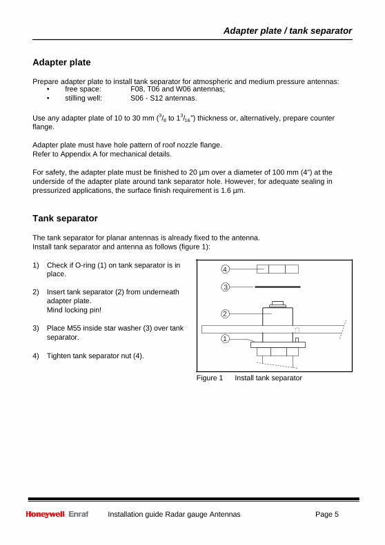
The tank separator for planar antennas is already fixed to the antenna. Install tank separator and antenna as follows (figure 1):
1) Check if O-ring (1) on tank separator is in 4
place.
3 2) Insert tank separator (2) from underneath
adapter plate. Mind locking pin! 2
3) Place M55 inside star washer (3) over tank
separator. 1
4) Tighten tank separator nut (4).
Figure 1 Install tank separator
Page 6 Installation guide Radar gauge Antennas
Installation F06 antenna
Free space 6" planar antenna
The 6" planar antenna (F06) can be installed on a 6" (or larger) roof nozzle or on a manhole. Refer to section: adapter plate / tank separator.
Antenna position The antenna can be positioned anywhere on the tank roof, except in the centre when the tank has a dome roof. For optimum accuracy, a minimum distance from the tank shell is recommended. For 97x SmartRadar the minimum distance becomes: 0.14 x tank height from tank shell (with AdvancedDSP software enabled) or 0.28 x tank height from tank shell (without AdvancedDSP software). For SmartRadar FlexLine the minimum distance becomes: 0.14 times tank height.
If possible, the radar beam should avoid large reflecting obstacles. It is recommended to select stem length so that antenna position is below roof nozzle.
Field orientation 6" planar antenna
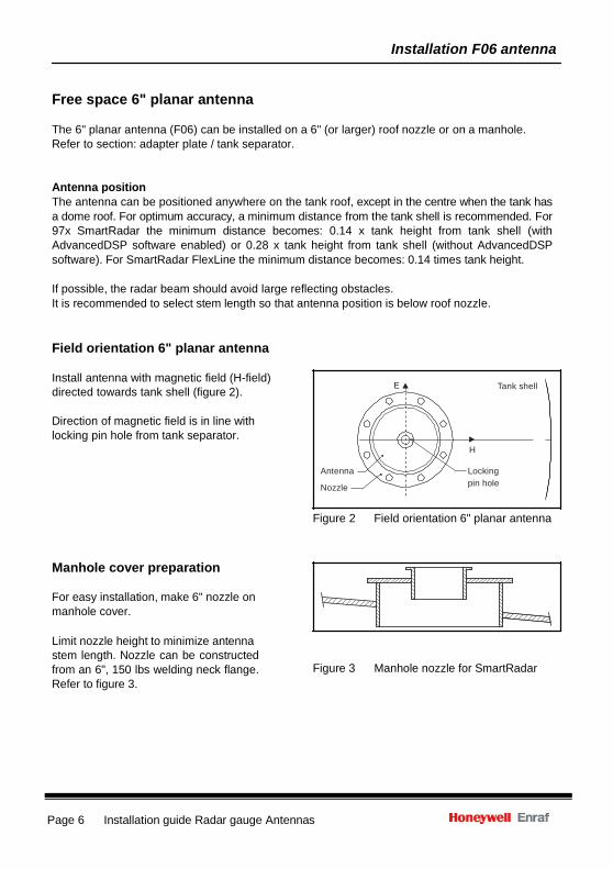
Install antenna with magnetic field (H-field) directed towards tank shell (figure 2).
Direction of magnetic field is in line with locking pin hole from tank separator.
E Tank shell
H
Antenna
Nozzle
Locking pin hole
Figure 2 Field orientation 6" planar antenna
Manhole cover preparation
For easy installation, make 6" nozzle on manhole cover.
Limit nozzle height to minimize antenna stem length. Nozzle can be constructed from an 6", 150 lbs welding neck flange. Refer to figure 3.
Figure 3 Manhole nozzle for SmartRadar
Installation guide Radar gauge Antennas Page 7
Installation F06 antenna
Install antenna with adapter plate on nozzle
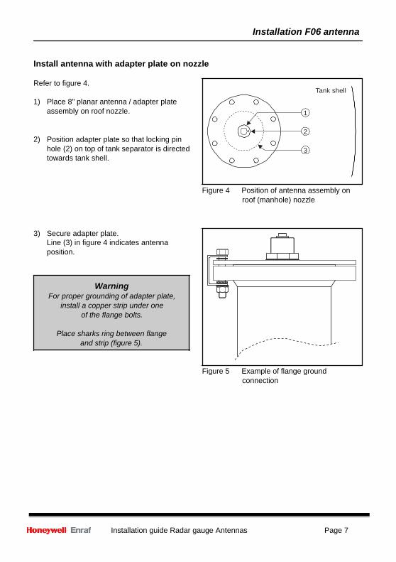
Refer to figure 4.
1) Place 8" planar antenna / adapter plate assembly on roof nozzle.
2) Position adapter plate so that locking pin hole (2) on top of tank separator is directed towards tank shell.
Tank shell
1 2 3
Figure 4 Position of antenna assembly on roof (manhole) nozzle
3) Secure adapter plate. Line (3) in figure 4 indicates antenna position.
Warning For proper grounding of adapter plate,
install a copper strip under one of the flange bolts.
Place sharks ring between flange
and strip (figure 5).
Figure 5 Example of flange ground connection
Page 8 Installation guide Radar gauge Antennas
Installation F08 antenna
Free space 8" planar antenna
The 8" planar antenna (F08) can be installed on a 8" (or larger) roof nozzle or on a manhole. Refer to section: adapter plate / tank separator.
Antenna position The antenna can be positioned anywhere on the tank roof, except in the centre when the tank has a dome roof. For optimum accuracy, a minimum distance from the tank shell is recommended. For 97x SmartRadar the minimum distance becomes: 0.1 x tank height from tank shell (with AdvancedDSP software enabled) or 0.15 x tank height from tank shell (without AdvancedDSP software). For SmartRadar FlexLine the minimum distance becomes: 0.1 times tank height. If possible, the radar beam should avoid large reflecting obstacles. It is recommended to select stem length so that antenna position is below roof nozzle.
Field orientation 8" planar antenna
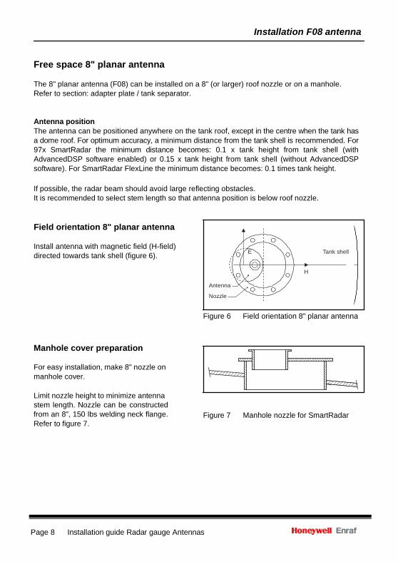
Install antenna with magnetic field (H-field) directed towards tank shell (figure 6).
E Tank shell
H
Antenna
Nozzle
Figure 6 Field orientation 8" planar antenna
Manhole cover preparation
For easy installation, make 8" nozzle on manhole cover.
Limit nozzle height to minimize antenna stem length. Nozzle can be constructed from an 8", 150 lbs welding neck flange. Refer to figure 7.
Figure 7 Manhole nozzle for SmartRadar
Installation guide Radar gauge Antennas Page 9
Installation F08 antenna
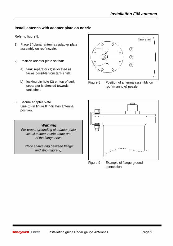
Install antenna with adapter plate on nozzle
Refer to figure 8.
1) Place 8" planar antenna / adapter plate assembly on roof nozzle.
2) Position adapter plate so that:
a) tank separator (1) is located as far as possible from tank shell;
b) locking pin hole (2) on top of tank
separator is directed towards tank shell.
3) Secure adapter plate. Line (3) in figure 8 indicates antenna position.
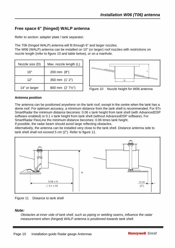
Warning For proper grounding of adapter plate,
install a copper strip under one of the flange bolts.
Place sharks ring between flange
and strip (figure 9).
Tank shell
1
2
3
Figure 8 Position of antenna assembly on
roof (manhole) nozzle Figure 9 Example of flange ground
connection
Installation W06 (T06) antenna
Page 10 Installation guide Radar gauge Antennas
Nozzle size (D)
Max. nozzle length (L)
10"
200 mm (8")
12"
350 mm (1' 2")
14" or larger
800 mm (2' 7½")
Free space 6" (hinged) WALP antenna
Refer to section: adapter plate / tank separator.
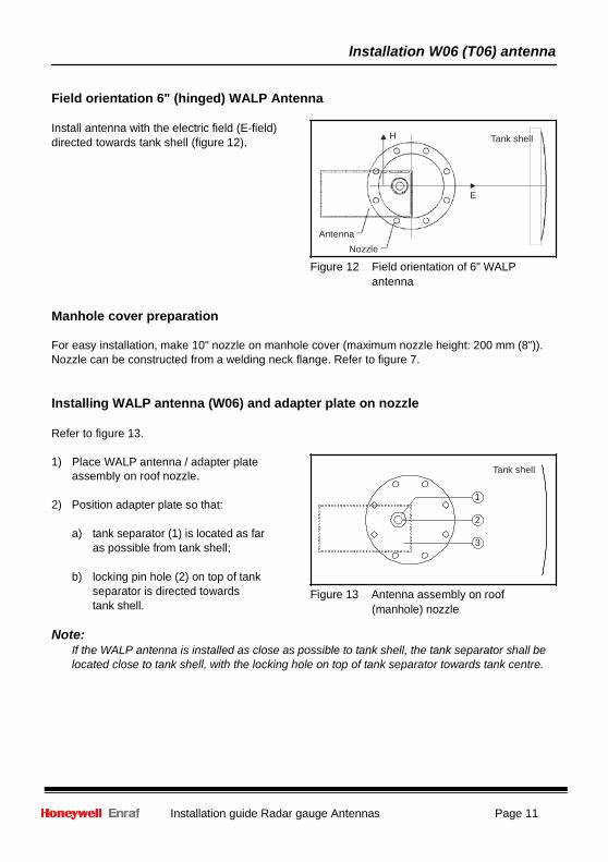
The T06 (hinged WALP) antenna will fit through 6" and larger nozzles. The W06 (WALP) antenna can be installed on 10" (or larger) roof nozzles with restrictions on nozzle length (refer to figure 10 and table below), or on a manhole.
L
D
Figure 10 Nozzle height for W06 antenna
Antenna position The antenna can be positioned anywhere on the tank roof, except in the centre when the tank has a dome roof. For optimum accuracy, a minimum distance from the tank shell is recommended. For 97x SmartRadar the minimum distance becomes: 0.06 x tank height from tank shell (with AdvancedDSP software enabled) or 0.1 x tank height from tank shell (without AdvancedDSP software). For SmartRadar FlexLine the minimum distance becomes: 0.06 times tank height. If possible, the radar beam should avoid large reflecting obstacles. Alternatively, the antenna can be installed very close to the tank shell. Distance antenna side to tank shell shall not exceed 5 cm (2"). Refer to figure 11.
H
0.06 x H
( 0.1 x H) 5 cm
(2”)
Figure 11 Distance to tank shell
Note: Obstacles at inner side of tank shell, such as piping or welding seams, influence the radar measurement when (hinged) WALP antenna is positioned towards tank shell.
Installation W06 (T06) antenna
Installation guide Radar gauge Antennas Page 11
Field orientation 6" (hinged) WALP Antenna
Install antenna with the electric field (E-field) directed towards tank shell (figure 12).
H Tank shell
E
Antenna Nozzle
Figure 12 Field orientation of 6" WALP antenna
Manhole cover preparation
For easy installation, make 10" nozzle on manhole cover (maximum nozzle height: 200 mm (8")). Nozzle can be constructed from a welding neck flange. Refer to figure 7.
Installing WALP antenna (W06) and adapter plate on nozzle
Refer to figure 13.
1) Place WALP antenna / adapter plate assembly on roof nozzle.
2) Position adapter plate so that:
a) tank separator (1) is located as far
as possible from tank shell;
b) locking pin hole (2) on top of tank separator is directed towards tank shell.
Tank shell
1
2
3
Figure 13 Antenna assembly on roof
(manhole) nozzle
Note: If the WALP antenna is installed as close as possible to tank shell, the tank separator shall be located close to tank shell, with the locking hole on top of tank separator towards tank centre.
Installation D04 antenna
Page 12 Installation guide Radar gauge Antennas
3) Secure adapter plate. Line (3) in figure 13 indicates antenna position, when installed towards the tank centre.
Warning For proper grounding of adapter plate, install a copper strip under one of the flange bolts.
Place shark rings between flange and strip (figure 9).
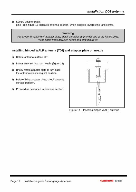
Installing hinged WALP antenna (T06) and adapter plate on nozzle
1) Rotate antenna surface 90°
2) Lower antenna into roof nozzle (figure 14).
3) Briefly rotate adapter plate to turn back the antenna into its original position.
4) Before fixing adapter plate, check antenna
surface position.
5) Proceed as described in previous section.
Figure 14 Inserting hinged WALP antenna
Installation D04 antenna
Installation guide Radar gauge Antennas Page 13
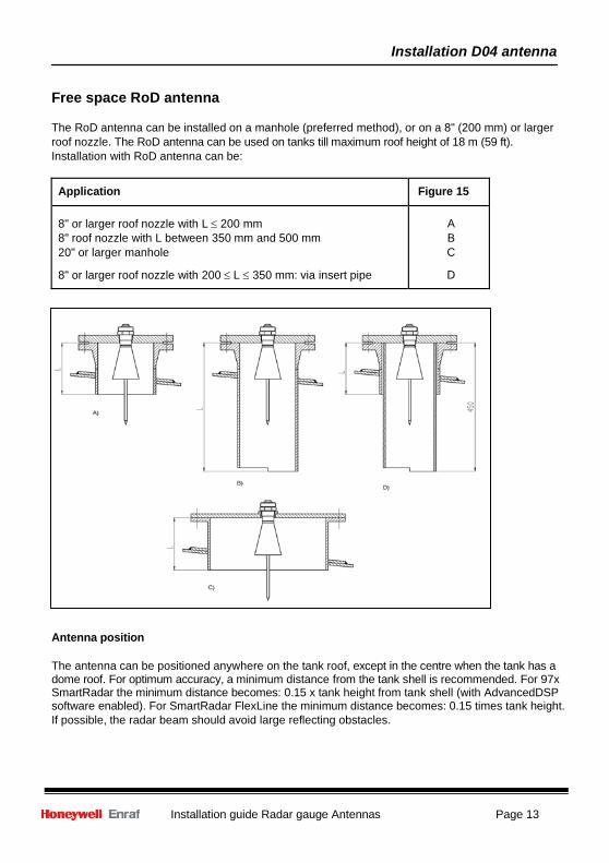
Free space RoD antenna
The RoD antenna can be installed on a manhole (preferred method), or on a 8" (200 mm) or larger roof nozzle. The RoD antenna can be used on tanks till maximum roof height of 18 m (59 ft). Installation with RoD antenna can be:
Application Figure 15
8" or larger roof nozzle with L ≤ 200 mm 8" roof nozzle with L between 350 mm and 500 mm 20" or larger manhole
8" or larger roof nozzle with 200 ≤ L ≤ 350 mm: via insert pipe
A B C
D
Figure 15 RoD antenna installation examples
Antenna position
The antenna can be positioned anywhere on the tank roof, except in the centre when the tank has a dome roof. For optimum accuracy, a minimum distance from the tank shell is recommended. For 97x SmartRadar the minimum distance becomes: 0.15 x tank height from tank shell (with AdvancedDSP software enabled). For SmartRadar FlexLine the minimum distance becomes: 0.15 times tank height. If possible, the radar beam should avoid large reflecting obstacles.
Installation D04 antenna
Page 14 Installation guide Radar gauge Antennas
Installing RoD antenna on manhole
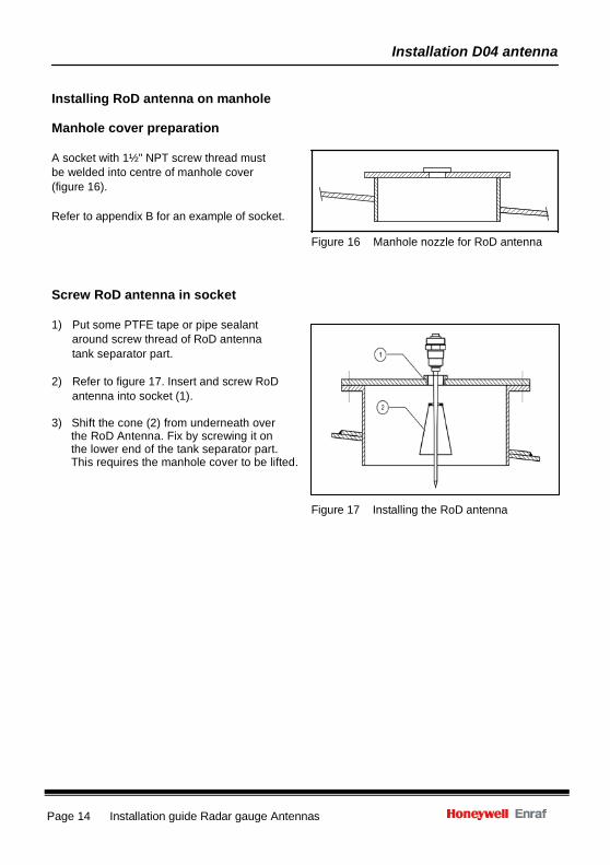
Manhole cover preparation
A socket with 1½" NPT screw thread must be welded into centre of manhole cover (figure 16).
Refer to appendix B for an example of socket.
Figure 16 Manhole nozzle for RoD antenna
Screw RoD antenna in socket
1) Put some PTFE tape or pipe sealant around screw thread of RoD antenna tank separator part.
2) Refer to figure 17. Insert and screw RoD
antenna into socket (1). 3) Shift the cone (2) from underneath over the RoD Antenna. Fix by screwing it on the lower end of the tank separator part. This requires the manhole cover to be lifted.
Figure 17 Installing the RoD antenna
Installation D04 antenna
Installation guide Radar gauge Antennas Page 15
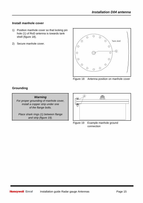
Install manhole cover
1) Position manhole cover so that locking pin hole (1) of RoD antenna is towards tank shell (figure 18).
2) Secure manhole cover.
Tank shell
1
Figure 18 Antenna position on manhole cover
Grounding
Warning For proper grounding of manhole cover,
install a copper strip under one of the flange bolts.
Place shark rings (1) between flange
and strip (figure 19).
1 Figure 19 Example manhole ground
connection
Installation D04 antenna
Page 16 Installation guide Radar gauge Antennas
Installing RoD antenna on roof nozzle
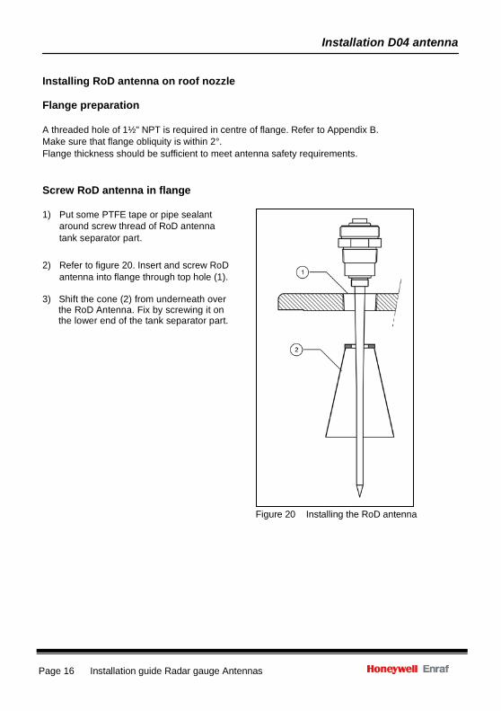
Flange preparation
A threaded hole of 1½" NPT is required in centre of flange. Refer to Appendix B. Make sure that flange obliquity is within 2°. Flange thickness should be sufficient to meet antenna safety requirements.
Screw RoD antenna in flange
1) Put some PTFE tape or pipe sealant around screw thread of RoD antenna tank separator part.
2) Refer to figure 20. Insert and screw RoD antenna into flange through top hole (1).
3) Shift the cone (2) from underneath over the RoD Antenna. Fix by screwing it on the lower end of the tank separator part.
Figure 20 Installing the RoD antenna
Installation D04 antenna
Installation guide Radar gauge Antennas Page 17
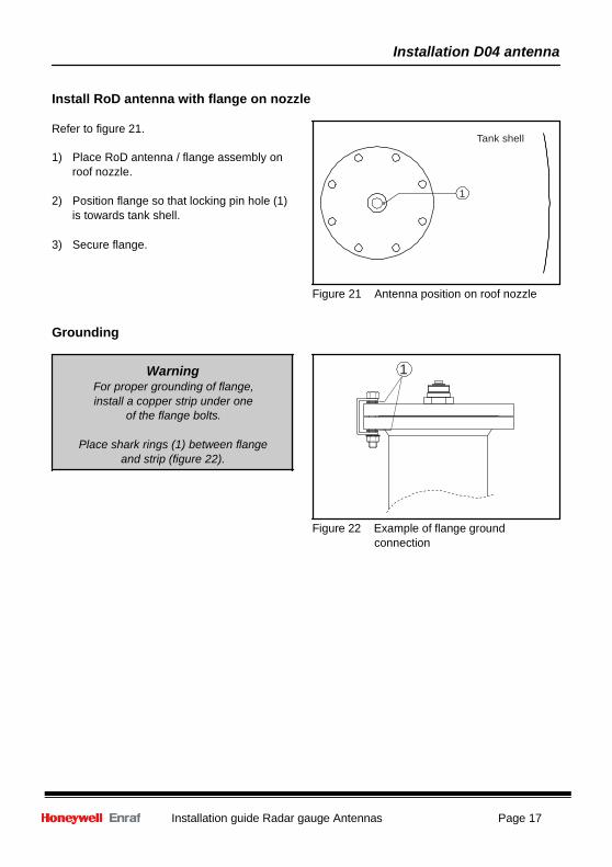
Install RoD antenna with flange on nozzle
Refer to figure 21.
1) Place RoD antenna / flange assembly on roof nozzle.
2) Position flange so that locking pin hole (1)
is towards tank shell.
3) Secure flange.
Tank shell
1
Figure 21 Antenna position on roof nozzle
Grounding
Warning 1 For proper grounding of flange, install a copper strip under one
of the flange bolts.
Place shark rings (1) between flange and strip (figure 22).
Figure 22 Example of flange ground connection
Page 18 Installation guide Radar gauge Antennas
Installation S06 - S12 antenna
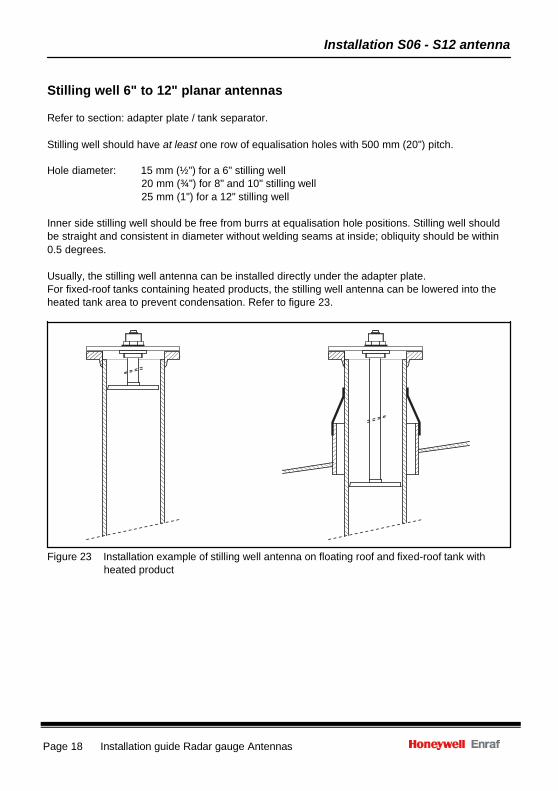
Stilling well 6" to 12" planar antennas
Refer to section: adapter plate / tank separator.
Stilling well should have at least one row of equalisation holes with 500 mm (20") pitch.
Hole diameter: 15 mm (½") for a 6" stilling well 20 mm (¾") for 8" and 10" stilling well 25 mm (1") for a 12" stilling well
Inner side stilling well should be free from burrs at equalisation hole positions. Stilling well should be straight and consistent in diameter without welding seams at inside; obliquity should be within 0.5 degrees.
Usually, the stilling well antenna can be installed directly under the adapter plate. For fixed-roof tanks containing heated products, the stilling well antenna can be lowered into the heated tank area to prevent condensation. Refer to figure 23.
Figure 23 Installation example of stilling well antenna on floating roof and fixed-roof tank with heated product
Installation guide Radar gauge Antennas Page 19
1
Installation S06 - S12 antenna
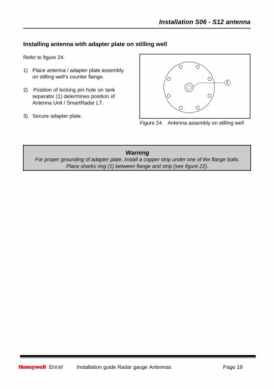
Installing antenna with adapter plate on stilling well
Refer to figure 24.
1) Place antenna / adapter plate assembly on stilling well's counter flange.
2) Position of locking pin hole on tank
separator (1) determines position of Antenna Unit / SmartRadar LT.
3) Secure adapter plate.
Figure 24 Antenna assembly on stilling well
Warning For proper grounding of adapter plate, install a copper strip under one of the flange bolts.
Place sharks ring (1) between flange and strip (see figure 22).
Installation H04 antenna
Page 20 Installation guide Radar gauge Antennas
16 8
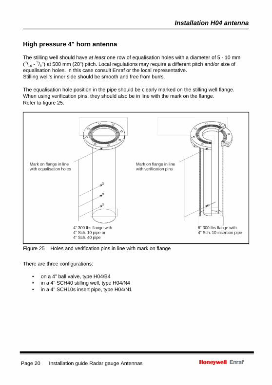
High pressure 4" horn antenna
The stilling well should have at least one row of equalisation holes with a diameter of 5 - 10 mm (3/ - 3/ ") at 500 mm (20") pitch. Local regulations may require a different pitch and/or size of equalisation holes. In this case consult Enraf or the local representative. Stilling well’s inner side should be smooth and free from burrs.
The equalisation hole position in the pipe should be clearly marked on the stilling well flange. When using verification pins, they should also be in line with the mark on the flange. Refer to figure 25.
Mark on flange in line with equalisation holes
4" 300 lbs flange with 4" Sch. 10 pipe or 4" Sch. 40 pipe
Mark on flange in line with verification pins
6" 300 lbs flange with 4" Sch. 10 insertion pipe
Figure 25 Holes and verification pins in line with mark on flange
There are three configurations:
• on a 4" ball valve, type H04/B4 • in a 4" SCH40 stilling well, type H04/N4 • in a 4" SCH10s insert pipe, type H04/N1
Installation H04 antenna
Installation guide Radar gauge Antennas Page 21
16
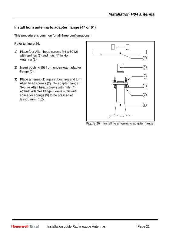
Install horn antenna to adapter flange (4" or 6")
This procedure is common for all three configurations.
Refer to figure 26.
1) Place four Allen head screws M6 x 60 (2) with springs (3) and nuts (4) in Horn Antenna (1). 6
2) Insert bushing (5) from underneath adapter 5
flange (6). 4
3) Place antenna (1) against bushing and turn Allen head screws (2) into adapter flange. Secure Allen head screws with nuts (4) 3 against adapter flange. Leave sufficient space for springs (3) to be pressed at 2 least 8 mm (5/ ").
1
Figure 26 Installing antenna to adapter flange
Installation H04 antenna
Page 22 Installation guide Radar gauge Antennas
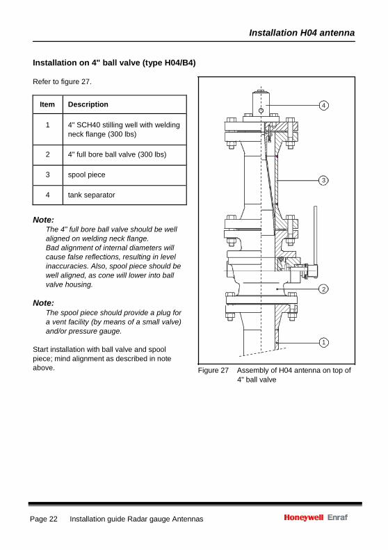
Item Description
1
4" SCH40 stilling well with welding neck flange (300 lbs)
2
4" full bore ball valve (300 lbs)
3
spool piece
4
tank separator
Installation on 4" ball valve (type H04/B4)
Refer to figure 27.
4
3
Note: The 4” full bore ball valve should be well aligned on welding neck flange. Bad alignment of internal diameters will cause false reflections, resulting in level inaccuracies. Also, spool piece should be well aligned, as cone will lower into ball valve housing.
Note:
The spool piece should provide a plug for a vent facility (by means of a small valve) and/or pressure gauge.
Start installation with ball valve and spool piece; mind alignment as described in note above.
2
1 Figure 27 Assembly of H04 antenna on top of
4" ball valve
Installation H04 antenna
Installation guide Radar gauge Antennas Page 23
Place horn antenna with 4" adapter flange in spool piece
1) Place 4" gasket on spool piece flange.
2) Carefully lower the antenna/adapter flange assembly inside spool piece. Do not yet fix adapter flange to spool piece.
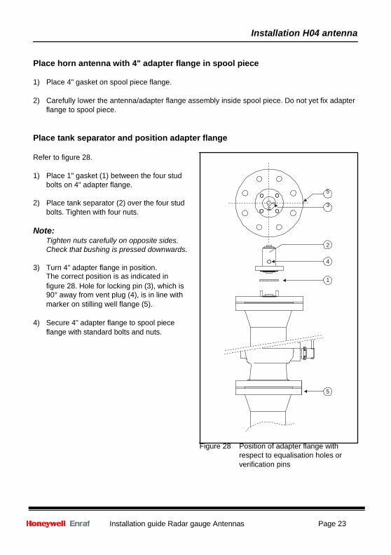
Place tank separator and position adapter flange
Refer to figure 28.
1) Place 1" gasket (1) between the four stud bolts on 4" adapter flange.
5
2) Place tank separator (2) over the four stud 3 bolts. Tighten with four nuts.
Note:
Tighten nuts carefully on opposite sides. 2
Check that bushing is pressed downwards. 4
3) Turn 4" adapter flange in position. The correct position is as indicated in 1 figure 28. Hole for locking pin (3), which is 90° away from vent plug (4), is in line with marker on stilling well flange (5).
4) Secure 4" adapter flange to spool piece
flange with standard bolts and nuts.
5
Figure 28 Position of adapter flange with respect to equalisation holes or verification pins
Installation H04 antenna
Page 24 Installation guide Radar gauge Antennas
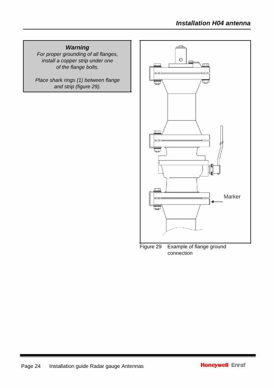
Warning
For proper grounding of all flanges, install a copper strip under one
of the flange bolts.
Place shark rings (1) between flange and strip (figure 29).
Marker
Figure 29 Example of flange ground
connection
Installation H04 antenna
Installation guide Radar gauge Antennas Page 25
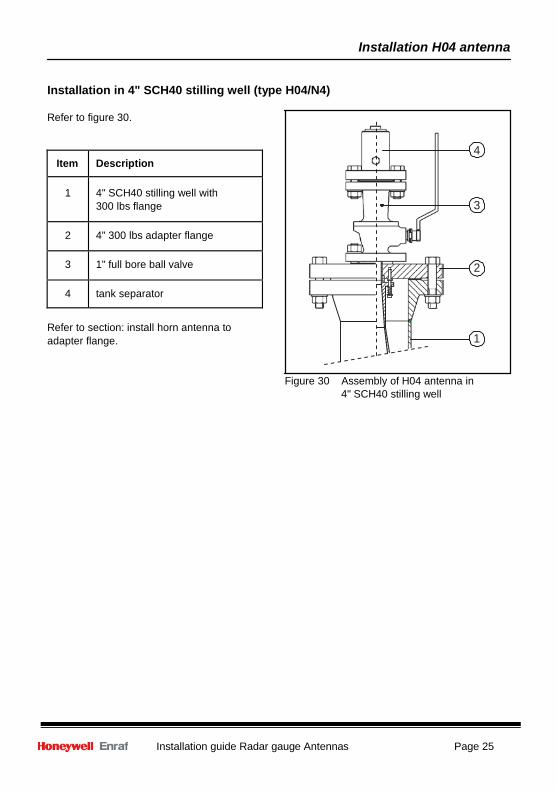
Item Description
1
4" SCH40 stilling well with 300 lbs flange
2
4" 300 lbs adapter flange
3
1" full bore ball valve
4
tank separator
Installation in 4" SCH40 stilling well (type H04/N4)
Refer to figure 30.
4
3
2
Refer to section: install horn antenna to adapter flange. 1
Figure 30 Assembly of H04 antenna in 4" SCH40 stilling well
Installation H04 antenna
Page 26 Installation guide Radar gauge Antennas
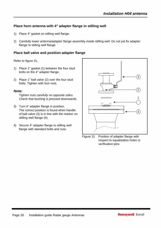
Place horn antenna with 4" adapter flange in stilling well
1) Place 4" gasket on stilling well flange.
2) Carefully lower antenna/adapter flange assembly inside stilling well. Do not yet fix adapter flange to stilling well flange.
Place ball valve and position adapter flange
Refer to figure 31.
1) Place 1" gasket (1) between the four stud
bolts on the 4" adapter flange. 3
2) Place 1" ball valve (2) over the four stud bolts. Tighten with four nuts.
Note: 2 Tighten nuts carefully on opposite sides. Check that bushing is pressed downwards. 1
3) Turn 4" adapter flange in position.
The correct position is found when handle 4 of ball valve (3) is in line with the marker on stilling well flange (4).
4) Secure 4" adapter flange to stilling well
flange with standard bolts and nuts.
Figure 31 Position of adapter flange with respect to equalisation holes or verification pins
Installation H04 antenna
Installation guide Radar gauge Antennas Page 27
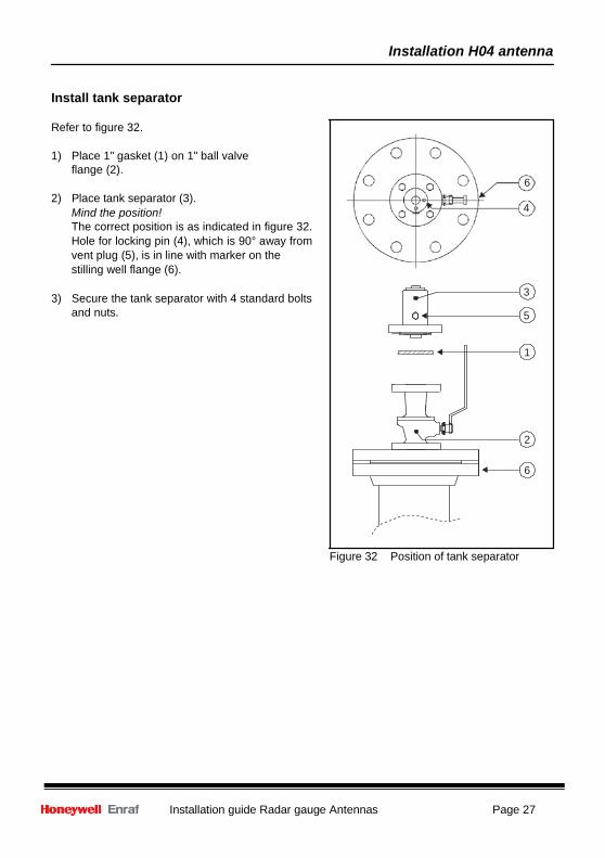
Install tank separator
Refer to figure 32.
1) Place 1" gasket (1) on 1" ball valve flange (2).
6 2) Place tank separator (3).
Mind the position! 4 The correct position is as indicated in figure 32. Hole for locking pin (4), which is 90° away from vent plug (5), is in line with marker on the stilling well flange (6).
3) Secure the tank separator with 4 standard bolts 3 and nuts. 5
1
2
6
Figure 32 Position of tank separator

Installation H04 antenna
Page 28 Installation guide Radar gauge Antennas
Warning For proper grounding of all flanges,
install a copper strip under one of the flange bolts.
Place shark rings (1) between flange
and strip (figure 33).
Marker
Figure 33 Example of flange ground connection
Installation H04 antenna
Installation guide Radar gauge Antennas Page 29
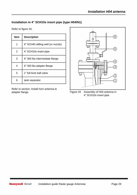
Item Description
1
6" SCH40 stilling well (or nozzle)
2
4" SCH10s insert pipe
3
6" 300 lbs intermediate flange
4
6" 300 lbs adapter flange
5
1" full bore ball valve
6
tank separator
Installation in 4" SCH10s insert pipe (type H04/N1)
Refer to figure 34.
6
5
4
3
2
1
Refer to section: Install horn antenna to adapter flange.
Figure 34 Assembly of H04 antenna in
4" SCH10s insert pipe
Installation H04 antenna
Page 30 Installation guide Radar gauge Antennas
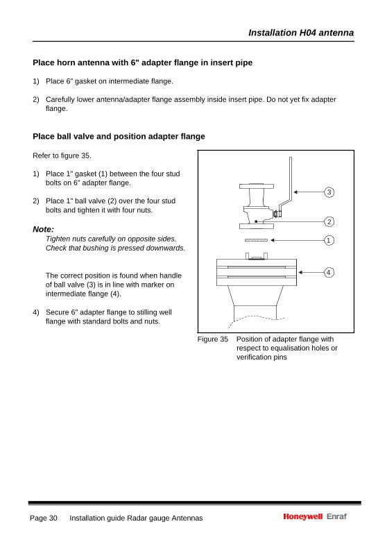
Place horn antenna with 6" adapter flange in insert pipe
1) Place 6" gasket on intermediate flange.
2) Carefully lower antenna/adapter flange assembly inside insert pipe. Do not yet fix adapter flange.
Place ball valve and position adapter flange
Refer to figure 35.
1) Place 1" gasket (1) between the four stud bolts on 6" adapter flange.
3 2) Place 1" ball valve (2) over the four stud
bolts and tighten it with four nuts. 2
Note: Tighten nuts carefully on opposite sides. 1 Check that bushing is pressed downwards.
The correct position is found when handle 4 of ball valve (3) is in line with marker on intermediate flange (4).
4) Secure 6" adapter flange to stilling well
flange with standard bolts and nuts.
Figure 35 Position of adapter flange with respect to equalisation holes or verification pins
Installation H04 antenna
Installation guide Radar gauge Antennas Page 31
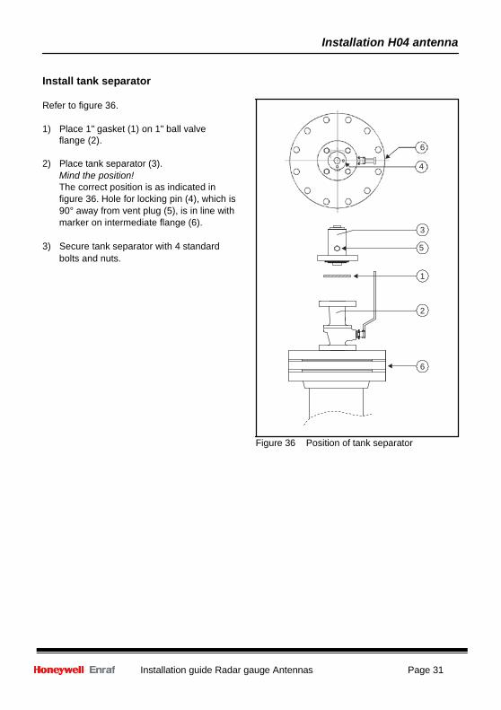
Install tank separator
Refer to figure 36.
1) Place 1" gasket (1) on 1" ball valve flange (2).
6
2) Place tank separator (3). 4 Mind the position! The correct position is as indicated in figure 36. Hole for locking pin (4), which is 90° away from vent plug (5), is in line with marker on intermediate flange (6).
3
3) Secure tank separator with 4 standard 5 bolts and nuts.
1
2
6
Figure 36 Position of tank separator
Installation H04 antenna
Page 32 Installation guide Radar gauge Antennas
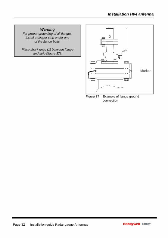
Warning For proper grounding of all flanges,
install a copper strip under one of the flange bolts.
Place shark rings (1) between flange
and strip (figure 37).
Marker
Figure 37 Example of flange ground connection
Appendix
Installation guide Radar gauge Antennas Page 33
T
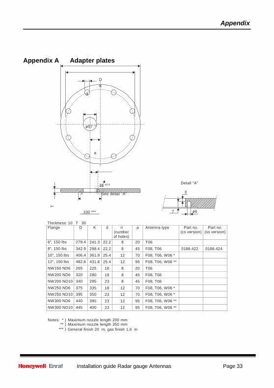
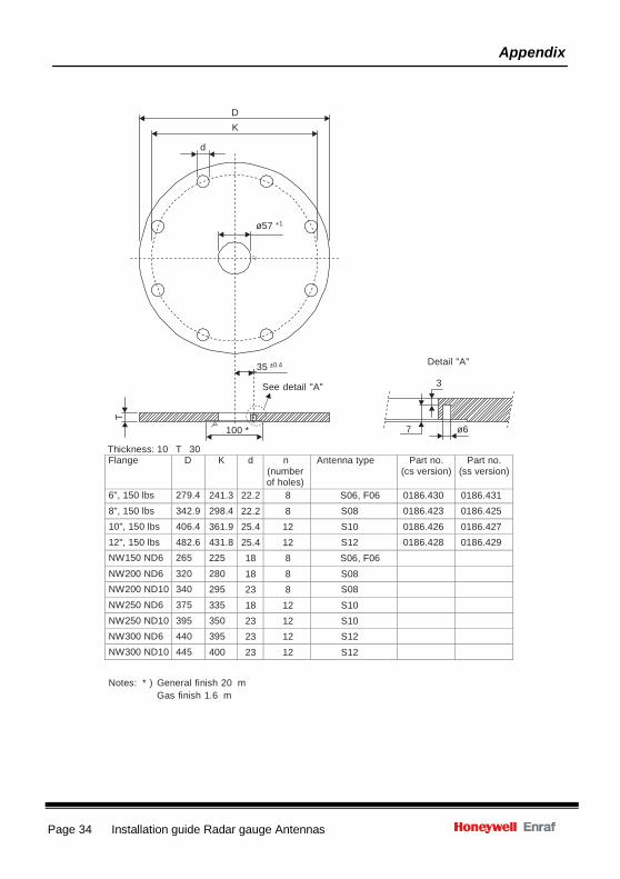
Appendix A Adapter plates
D K
d
ø57 +1
a
35 ±0.4
See detail "A"
Detail "A" 3
100 *** 7 ø6
Thickness: 10 T 30 Flange D K d n
(number of holes)
a Antenna type Part no. (cs version) Part no.
(ss version) 6", 150 lbs 279.4 241.3 22.2 8 20 T06 8", 150 lbs 342.9 298.4 22.2 8 45 F08, T06 0186.422 0186.424 10", 150 lbs 406.4 361.9 25.4 12 70 F08, T06, W06 * 12", 150 lbs 482.6 431.8 25.4 12 95 F08, T06, W06 ** NW150 ND6 265 225 18 8 20 T06 NW200 ND6 320 280 18 8 45 F08, T06 NW200 ND10 340 295 23 8 45 F08, T06 NW250 ND6 375 335 18 12 70 F08, T06, W06 * NW250 ND10 395 350 23 12 70 F08, T06, W06 * NW300 ND6 440 395 23 12 95 F08, T06, W06 ** NW300 ND10 445 400 23 12 95 F08, T06, W06 **
Notes: * ) Maximum nozzle length 200 mm
** ) Maximum nozzle length 350 mm *** ) General finish 20 m, gas finish 1.6 m
Appendix
Page 34 Installation guide Radar gauge Antennas
T
D K
d
ø57 +1
35 ±0.4
See detail "A"
Detail "A" 3
Thickness: 10 T 30
100 * 7 ø6
Flange D K d n (number of holes)
Antenna type Part no. (cs version) Part no.
(ss version) 6", 150 lbs 279.4 241.3 22.2 8 S06, F06 0186.430 0186.431 8", 150 lbs 342.9 298.4 22.2 8 S08 0186.423 0186.425 10", 150 lbs 406.4 361.9 25.4 12 S10 0186.426 0186.427 12", 150 lbs 482.6 431.8 25.4 12 S12 0186.428 0186.429 NW150 ND6 265 225 18 8 S06, F06 NW200 ND6 320 280 18 8 S08 NW200 ND10 340 295 23 8 S08 NW250 ND6 375 335 18 12 S10 NW250 ND10 395 350 23 12 S10 NW300 ND6 440 395 23 12 S12 NW300 ND10 445 400 23 12 S12
Notes: * ) General finish 20 m
Gas finish 1.6 m
Appendix
Installation guide Radar gauge Antennas Page 35
25
15
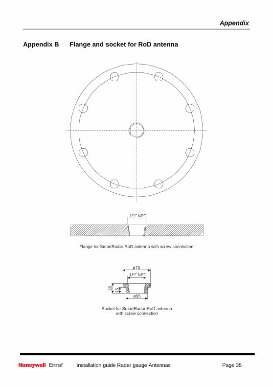
Appendix B Flange and socket for RoD antenna
11/2" NPT
Flange for SmartRadar RoD antenna with screw connection
ø70 11/2" NPT
ø55
Socket for SmartRadar RoD antenna
with screw connection
Appendix
Page 36 Installation guide Radar gauge Antennas
Stem
leng
th
23
(15/
16" )
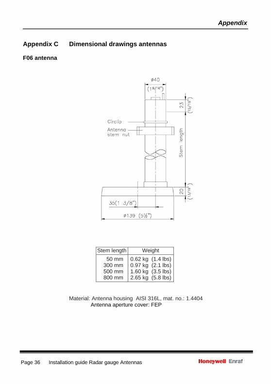
Appendix C Dimensional drawings antennas
F06 antenna
Stem length Weight 50 mm
300 mm 500 mm 800 mm
0.62 kg (1.4 lbs) 0.97 kg (2.1 lbs) 1.60 kg (3.5 lbs) 2.65 kg (5.8 lbs)
Material: Antenna housing AISI 316L, mat. no.: 1.4404 Antenna aperture cover: FEP
Appendix
Installation guide Radar gauge Antennas Page 37
Ste
m le
ngth
20
( 1
3/16
" ) 23
(1
5/16
" )
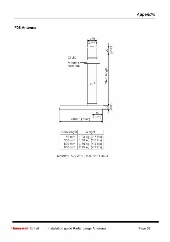
F08 Antenna
ø40 (1 9/16")
Circlip Antenna stem nut
ø189.5 (7 7/16")
45 (1 3/4" )
Stem length Weight 50 mm
300 mm 500 mm 800 mm
1.23 kg (2.7 lbs) 1.58 kg (3.5 lbs) 1.86 kg (4.1 lbs) 2.25 kg (4.9 lbs)
Material: AISI 316L, mat. no.: 1.4404
Appendix
Page 38 Installation guide Radar gauge Antennas
100
(3 15
/16"
)
148
(5 13
/16"
) S
tem
leng
th
17
( 11/
16" )
23
(15/
16" )
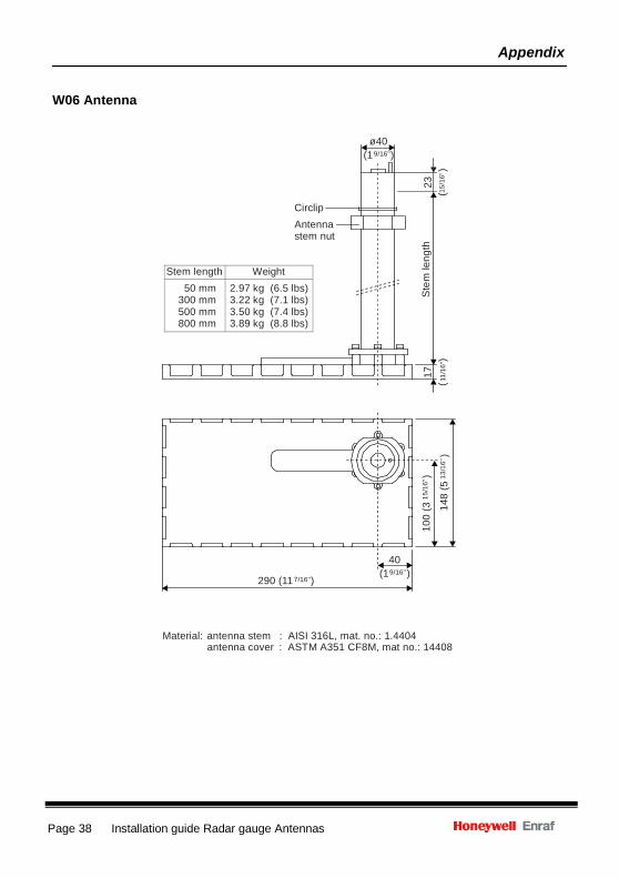
W06 Antenna
ø40 (1 9/16" )
Circlip Antenna stem nut
Stem length Weight
50 mm 300 mm 500 mm 800 mm
2.97 kg (6.5 lbs) 3.22 kg (7.1 lbs) 3.50 kg (7.4 lbs) 3.89 kg (8.8 lbs)
290 (11 7/16")
40 (19/16" )
Material: antenna stem : AISI 316L, mat. no.: 1.4404 antenna cover : ASTM A351 CF8M, mat no.: 14408
Appendix
Installation guide Radar gauge Antennas Page 39
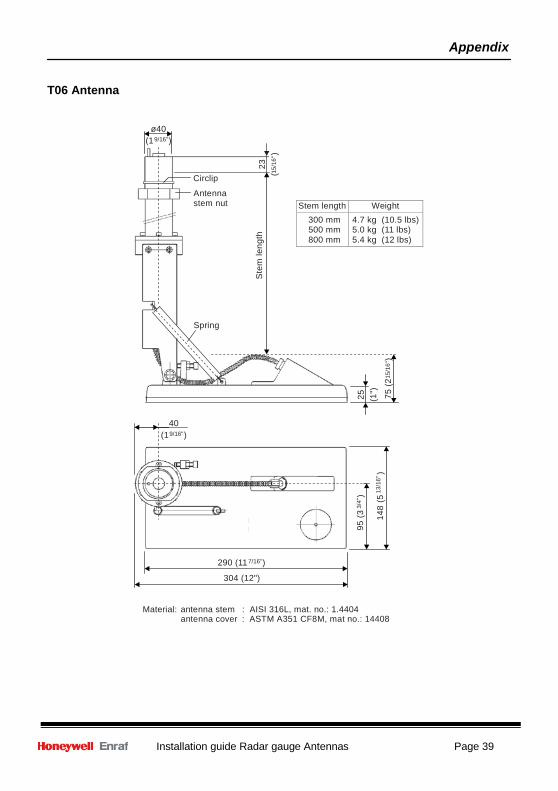
Stem length Weight 300 mm 500 mm 800 mm
4.7 kg (10.5 lbs) 5.0 kg (11 lbs) 5.4 kg (12 lbs)
S
tem
leng
th
23
(15/
16" )
95 (3
3/4"
) 25
(1
")
75 (2
15/1
6")
148
(5 13
/16"
)
T06 Antenna
ø40 (1 9/16" )
Circlip
Antenna stem nut
Spring
40 (1 9/16" )
290 (11 7/16")
304 (12")
Material: antenna stem : AISI 316L, mat. no.: 1.4404 antenna cover : ASTM A351 CF8M, mat no.: 14408
Appendix
Page 40 Installation guide Radar gauge Antennas
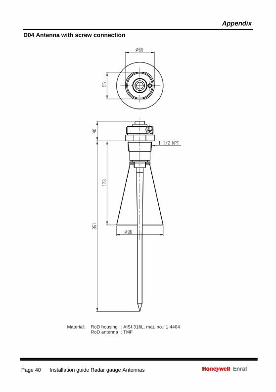
D04 Antenna with screw connection
Material: RoD housing : AISI 316L, mat. no.: 1.4404 RoD antenna : TMF
Appendix
Installation guide Radar gauge Antennas Page 41
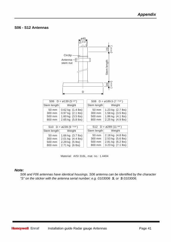
S08 D = ø189.5 (7 7/16" ) Stem length Weight
50 mm 300 mm 500 mm 800 mm
1.23 kg (2.7 lbs) 1.58 kg (3.5 lbs) 1.86 kg (4.1 lbs) 2.25 kg (4.9 lbs)
S12 D = ø289 (11 3/8" ) Stem length Weight
50 mm 300 mm 500 mm 800 mm
2.18 kg (4.8 lbs) 2.53 kg (5.6 lbs) 2.81 kg (6.2 lbs) 3.23 kg (7.1 lbs)
Ste
m le
ngth
20
( 1
3/16
" ) 23
(1
5/16
" )
S06 - S12 Antennas
ø40 (1 9/16")
Circlip Antenna stem nut
D
S06 D = ø139 (5 1/2")
Stem length Weight 50 mm
300 mm 500 mm 800 mm
0.62 kg (1.4 lbs) 0.97 kg (2.1 lbs) 1.60 kg (3.5 lbs) 2.65 kg (5.8 lbs)
S10 D = ø239 (9 7/16" )
Stem length Weight 50 mm
300 mm 500 mm 800 mm
1.66 kg (3.7 lbs) 2.01 kg (4.4 lbs) 2.29 kg (5 lbs) 2.71 kg (6 lbs)
Material: AISI 316L, mat. no.: 1.4404
Note: S06 and F06 antennas have identical housings. S06 antenna can be identified by the character “S” on the sticker with the antenna serial number; e.g. 0103006 S, or S 0103006.
Appendix
Page 42 Installation guide Radar gauge Antennas
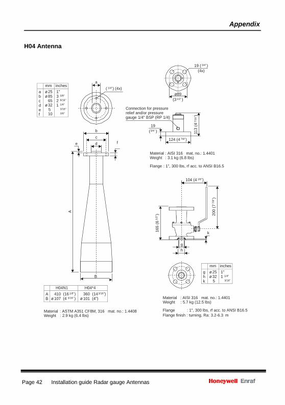
mm inches a b c d e f
ø 25 ø 85
65 ø 32
5 10
1" 3 3/8" 2 9/16" 1 1/4"
3/16" 3/8"
mm inches g h k
ø 25 ø 32
5 1" 1 1/4"
3/16" H04N1 H04*4
A B 410 (16 1/8" )
ø 107 (4 3/16" ) 360 (14 3/16") ø 101 (4")
A
165
(6 1/
2")
113
(4 7/
16" )
200
(7 7/
8")
H04 Antenna
19 ( 3/4" ) (4x)
a
( 1/4" ) (4x) Connection for pressure relief and/or pressure gauge 1/4" BSP (RP 1/4)
ø89 (3 1/2" )
b c
e d f
19
(3/4" )
124 (4 7/8")
Material : AISI 316 mat. no.: 1.4401 Weight : 3.1 kg (6.8 lbs)
Flange : 1", 300 lbs, rf acc. to ANSI B16.5
104 (4 1/8")
k
g h
B
Material : AISI 316 mat. no.: 1.4401
Material : ASTM A351 CF8M, 316 mat. no.: 1.4408
Weight Flange
: 5.7 kg (12.5 lbs)
: 1", 300 lbs, rf acc. to ANSI B16.5 Weight : 2.9 kg (6.4 lbs) Flange finish : turning, Ra: 3.2-6.3 m
Installation guide Radar gauge Antennas Page 43
Appendix D Related publications
SmartRadar Safety instructions for installation, commissioning, operation and maintenance
Installation guide 970 SmartRadar ATi Installation guide 971 SmartRadar LTi Installation guide 973 SmartRadar LT Installation guide SmartRadar FlexLine
Instruction manual 970 SmartRadar Ati Instruction manual 971 SmartRadar LTi Instruction manual 973 SmartRadar LT Instruction manual SmartRadar FlexLine
Page 44 Installation guide Radar gauge Antennas
Delftechpark 39 2628 XJ Delft Tel. :+31 15 2701 100 E-mail : [email protected] Webiste: http://www.honeywellenraf.com PO Box 812 2600 AV Delft The Netherlands We at Honeywell Enraf are committed to excellence. Information in this publication is subject to change without notice Enraf is a registered trade mark. Enraf B.V. Netherlands