Embed Size (px)
Citation preview
RACK MOUNT - Rack Mount Connector Network Panel
MCNP
ORDERING CODE
The MCNP Connector Network Panel is an economical rack mountable patch panel for use with splicing of manufactured pigtails, preterminated cables and �eld-installable connectors. The cables are strain-relieved at the rear of the unit. The pivoting shelf can be equipped with either a splice tray holder or bend radius protection which guides, stores and organizes excess slack. This prevents damage to �bers prior to routing into couplings. The MCNP is used in installations where space is limited.
FEATURES
Splicing and termination optical cable in one boxAluminum material - low weight and shipment costsExtended (3 coupling panels per 1U) version availableSplice cassette holder enables cable termination with the help of pigtail splicingAccommodates up to 24 �bers in 1 rack unitRemovable top cover provides unrestricted accessPivoting shelf eases connector routing and cable routingCable strain-relief and grounding provisionsAccepts industry standard connector typesFTTH use – microtubes holder includedPassed seismic tests according to ASME standards Approved for construction of nuclear power plant components
TECHNICAL SPECIFICATIONS
Note: 1) Splice Tray: CMS_01-09_EN-KNS Splice_trays CNPM coupling panel: CMS_24-01_EN-CNPM CNPM-XX-06 6 pcs ST, FC, SC, E2000, ... adapters CNPM-XX-08 8 pcs ST, FC, SC, E2000, ... adapters CNPM-XX-12 12 pcs SC, E2000 adaptersCAPM prewired cassette with pigtails and adapters: CMS_22-01_EN-CAPM
PART NUMBER
FIBER CAPACITY1 RACK UNITS
DIMENSIONS (HxWxD) mm
SHIP WGT (kg) CNPM-XX-06 CNPM-XX-08 CNPM-XX-12
MCNP – 1S 12 16 24 1 44 x 432 x 280 2.4 MCNP – 2S 24 32 48 2 88 x 432 x 280 3.8 MCNP – 3S 36 48 72 3 133 x 432 x 280 5.2 MCNP – 1E 18 24 36 1 44 x 432 x 280 2.4 MCNP – 2E 36 48 72 2 88 x 432 x 280 3.8 MCNP – 3V 72 96 144 3 133 x 432 x 280 5.5
Parts available separately:
1 MCNP-BU-X base unit6 MCNP-TS-1 twisting shelf7 MCNP-CP-1 front panel8 MCNP-TC top cover9 Pin FH-M5-3810 Pin FH-M3-3011 UH-1_var112 Screw CNMP
X=2,3 – rack unit
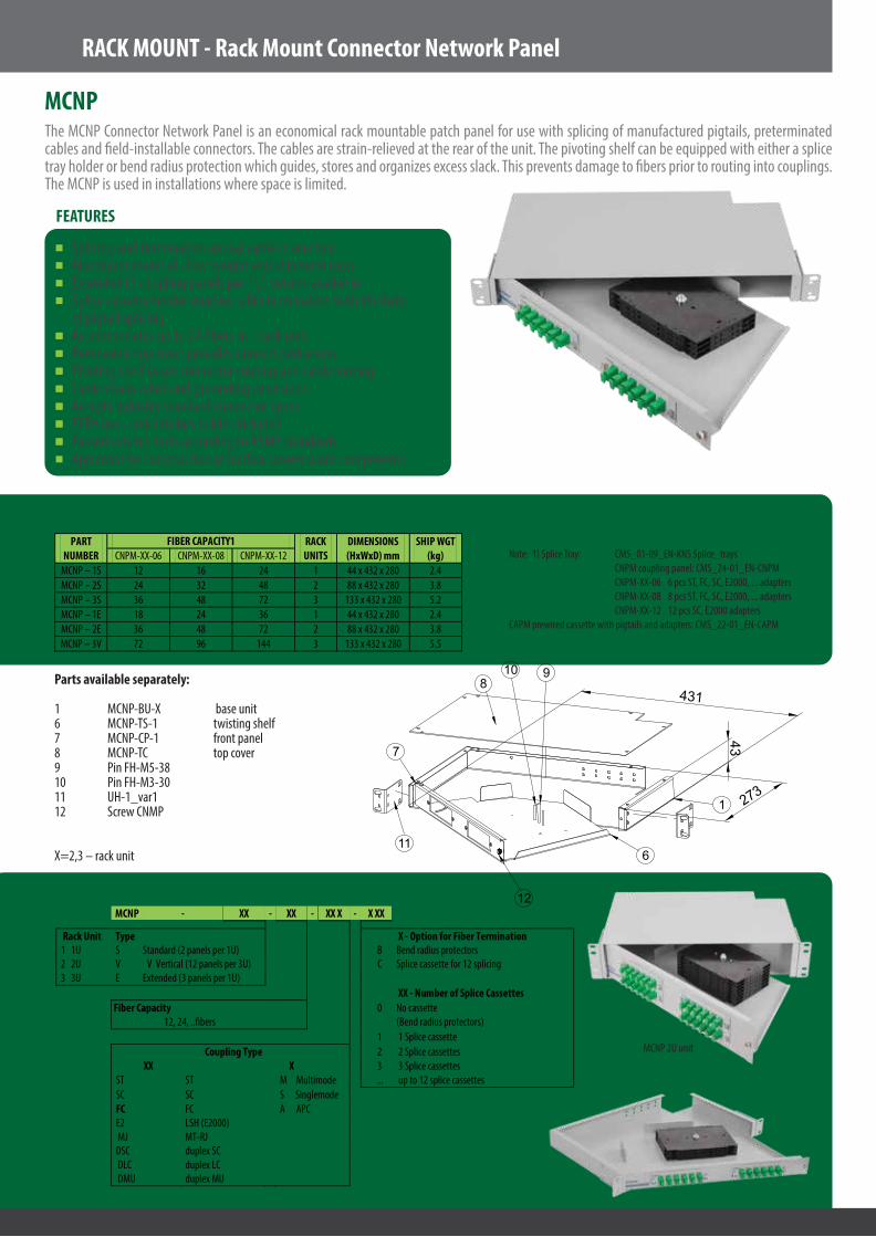
MCNP 2U unit
1
7
8
611
12
10 9
43
431
273
MCNP - XX - XX - XX X - X XX
Rack Unit Type X - Option for Fiber Termination 1 1U S Standard (2 panels per 1U) B Bend radius protectors 2 2U V V Vertical (12 panels per 3U) C Splice cassette for 12 splicing 3 3U E Extended (3 panels per 1U)
XX - Number of Splice Cassettes Fiber Capacity 0 No cassette
12, 24, ..�bers (Bend radius protectors) 1 1 Splice cassette Coupling Type 2 2 Splice cassettes XX X 3 3 Splice cassettes ST ST M Multimode ... up to 12 splice cassettes SC SC S Singlemode FC FC A APC E2 LSH (E2000) MJ MT-RJ DSC duplex SC DLC duplex LC DMU duplex MU