Embed Size (px)
Citation preview
Conditioning the air, releasing new opportunities.
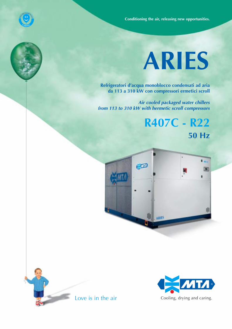
Refrigeratori d’acqua monoblocco condensati ad ariada 113 a 310 kW con compressori ermetici scroll
Air cooled packaged water chillersfrom 113 to 310 kW with hermetic scroll compressors
R407C - R2250 Hz
ARIES
®
Cooling, drying and caring.Love is in the air
ENVIRONMENTAL
CA R I N G
Conditioning the air, releasing new opportunities.
ARIES
®
Cooling, drying and caring.
Specifiche tecnicheTechnical specifications
Guida alla selezioneSelection guide
Prestazioni e dati tecniciR407C - R22 Performance and technical data
Prestazioni desurriscaldatore e recuperatore di calore, coefficienti correttiviDesuperheater and heat recovery performance, correction coefficients
Perdite di carico evaporatore, desurriscaldatore e recuperatore, limiti di funzionamento, coefficienti correttiviEvaporator, desuperheater and heat recovery pressure drops, operating limits, correction factors
Disegni di ingombroOverall dimensions
Guida all’installazioneInstallation guide
Elenco caratteristiche standard e optionalList of standard features and options
2
9
12
32
34
36
43
45
Indi
ce -
inde
x
EASYY000BD_V 07-04-2006 12.13 Pagina 1
AR
IES
1. General2. Versions3. Nameplate4. Testing5. Compressors6. Evaporator7. Condenser coils8. Fans motor9. Cooling circuit10. Desuperheater and heat recovery11. Structure and casing12. Power and control electrical panel13. Hydronic kit14. Control and management
1. General
The new range of “Aries” units is a series of air cooled packaged water
chillers with SCROLL type compressors and built-in microprocessor
control.
The management of each Aries chiller is entrusted to a microprocessor
control (denominated pCO2), which enables the management of 4
capacity steps. The user interface for all the machines is the new
semigraphic and backlighted LCD display denominated pGD.
The Aries chillers, with IP54 protection rating, are suitable for outdoor
installation. They have two independent cooling circuits, with two or
more compressors for each circuit. The power supply is 400/3/50.
Top quality brand components are carefully selected for these chillers
that are designed, produced and tested in compliance with ISO
9001:2000 standards
2. Versions
The ARIES chillers are available in three versions with nominal
capacities ranging from 113 kW to 319 kW:
N: suitable for ambient temperatures up to 48°C for R22 and 46°C
for R407C
SN: suitable for ambient temperatures up to 45°C for R22 and 43°C
for R407C with sound pressure level reduced by 5 dB(A)
compared to the “N” version, thanks to the use of low rpm fans.
SSN: suitable for ambient temperatures up to 43°C for R22 and 41°C
for R407C with sound pressure level reduced by 8 db(A)
compared to the SN version, thanks to the expansion of the
finned surface, improved soundproofing of the compressor
housing and more silent fans for all the models.
A version for high ambient temperature applications (H version) is also
available, though it is not featured in this catalogue.
3. Nameplate
Each chiller is identified by its nameplate:
AS XXX / ZZZ
Unit version:
N, SN, SSN
Cooling capacity (kW) of the “N” version R407C,
at 12°C, 7°C outlet water temperature and
ambient temperature at 35°C.
1. Generalità2. Versioni3. Sigla4. Collaudo5. Compressori6. Evaporatore7. Batterie Condensanti8. Elettroventilatori9. Circuito Frigorifero10. Desurriscaldaore e recuperatore di calore11. Struttura e Cofanatura12. Quadro elettrico di potenza e controllo13. Kit idronico14. Controllo e gestione
1. Generalità
La nuova gamma di refrigeratori d’acqua “Aries” sono unità
monoblocco condensate ad aria, con compressori SCROLL e controllo
a microprocessore.
La gestione di ogni refrigeratore Aries è affidata ad un controllo a
microprocessore (denominato pCO2) che consente la gestione da 4 gra-
dini di parzializzazione. Per tutte le macchine l’interfaccia utente è il
nuovo display LCD semigrafico e retroilluminato denominato pGD.
I refrigeratori hanno un grado di protezione IP54 e quindi sono adatti
per essere installati all’esterno. I Refrigeratori Aries hanno due circuiti
frigoriferi indipendenti con due o più compressori per ogni circuito,
l’alimentazione elettrica è 400/3/50.
Tutti i refrigeratori Aries sono realizzati utilizzando componenti di
primaria marca, e sono progettati, prodotti e controllati in conformità
alle norme ISO9001:2000.
2. Versioni
I refrigeratori ARIES sono disponibili con potenzialità nominali da 113
kW a 319 kW in tre versioni:
N: adatta per ambienti fino a 48°C per R22 e 46°C per R407C
SN: adatta per ambienti fino a 45°C per R22 e 43°C per R407C con
livello di pressione sonora ridotto di circa 5 dB(A) rispetto alla
versione “N”: la rumorosità viene ridotta grazie all’impiego di
ventilatori a basso numero di giri.
SSN: adatta per ambienti fino a 43°C per R22 e 41°C per R407C con
livello di pressione sonora ridotto di 8 db(A) rispetto alla versio-
ne SN grazie ad una maggiorazione della superficie alettata,
una migliore insonorizzazione acustica del vano compressori e
ventilatori più silenziosi per tutti i modelli.
E’ presente anche una versione per elevate temperature ambiente
(versione H) non descritta in questo catalogo.
3. Sigla
Ogni refrigeratore è identificato dalla sigla:
AS XXX / ZZZ
Versione della macchina:
N, SN, SSN
Potenza frigorifera in kW della versione “N” in
R407C, alle condizioni di ingresso acqua 12°C,
uscita acqua 7°C e temperatura ambiente 35°C.2
®
EASYY000BD_V 07-04-2006 12.13 Pagina 2
AR
IES
4. Collaudo
Tutti i refrigeratori vengono collaudati in cabine di collaudo di ampie
dimensioni e ciascun circuito viene fatto lavorare a pieno carico in modo
tale da poter valutare il corretto funzionamento di tutti i componenti.
In particolare vengono verificati:
• il corretto montaggio di tutti i componenti e la mancanza di fughe di
refrigerante;
• i test di sicurezza elettrici come prescritto dalla EN60204;
• il corretto funzionamento della centralina di controllo e il valore di
tutti i parametri di funzionamento;
• le sonde di temperatura e i trasduttori di pressione;
• le temperature di evaporazione e di condensazione, il surriscalda-
mento e il sottoraffreddamento, la potenza frigorifera resa, la potenza
elettrica assorbita e le perdite di carico dell’acqua attraverso
l’evaporatore, che fluisce in ciascun circuito della macchina in un
ambiente controllato (uscita acqua 7°C e temperatura ambiente 35°C).
All’installazione le macchine richiedono solo le connessioni elettriche
ed idrauliche assicurando un alto livello di affidabilità.
5. Compressori
I compressori sono di tipo ermetico scroll e presentano una serie di
vantaggi:
• una maggiore efficienza energetica (COP medio pari a 3.3)
• una sensibile riduzione del livello di pressione sonora (-6 dB(A)
rispetto ai tradizionali alternativi)
• ridotte vibrazioni
• assenza di smorzatori di vibrazioni sulla mandata dei compressori
I compressori sono dotati di motore elettrico a 2 poli protetto da un
modulo elettronico contro l’eccessiva temperatura degli avvolgimenti
dovuta ad un funzionamento anomalo, di dispositivo interno di
sicurezza per le sovrapressioni e di valvola di non ritorno interna sulla
mandata. Di serie, i compressori vengono protetti a monte da
interruttori magnetotermici. Tutti i refrigeratori ARIES sono equipaggiati
con 4 compressori. Inoltre sono montati su antivibranti in gomma e
installati in un vano acusticamente isolato con materassino fonoassor-
bente, chiuso da tre pannelli di facile rimozione per qualsiasi interven-
to di assistenza.
Optional:
• refrigerante R22
• rubinetti in aspirazione e mandata dei compressori
• resistenza carter nelle configurazioni previste per –20°C ambiente
6. Evaporatore
Ciascuna unità può essere provvista di due tipi di evaporatore (come
standard è previsto l’impiego dell’evaporatore a piastre):
- Evaporatore a piastre di acciaio inox saldobrasate a doppio circuito lato
refrigerante ed a singolo circuito lato utilizzo. Questi evaporatori sono
estremamente efficienti e compatti e richiedono pertanto pochissimo
spazio per il loro alloggiamento all’interno dell’unità. L’evaporatore è
protetto dal pericolo di ghiacciamento, causato da basse temperature di
evaporazione, dalla funzione antigelo della centralina elettronica che ne
controlla la temperatura di uscita dell’acqua. Inoltre, ogni evaporatore
monta un pressostato differenziale che lo protegge dalla mancanza di
flusso d’acqua. Tutti gli evaporatori impiegati nei refrigeratori ARIES
possono trattare anche soluzioni anticongelanti e, in generale, altri
4. Testing
All chillers are tested in large testing rooms at full load for a
considerable length of time to evaluate the integrity of each single
component.
In particular we check:
• the correct assembly of all components and the leaks of refrigerant
gas;
• the electrical safety tests as prescribed by the EN60204 standard;
• the correct operation of the microprocessor control and the set of all
parameters;
• the temperature sensors and the pressure transducers;
• the evaporating and the condensing temperatures, the superheating
and the subcooling, the supplied cooling capacity, the electrical
absorbed power and the pressure drop, through the evaporator, of
the water that flows in each machine circuit in a controlled ambient
(outlet water 7°C and ambient temperature 35°C).
The installation of the unit requires only electrical and hydraulic
connections, therefore ensuring a high level of reliability.
5. Compressors
The scroll type hermetic compressors offer a number of advantages:
• a higher energy efficiency (average COP 3.3)
• a considerable reduction of the noise level (-6 dB(A) compared to
traditional reciprocating)
• reduced vibrations
• absence of mufflers on the compressors discharge
The compressors are fitted with a 2 pole electric motor protected by an
electronic device against excessive part-widing temperatures caused by
irregular operation, an internal overpressure safety device and a
non-return valve on the discharge line. The compressors are protected
as standard by thermal-magnetic switches installed upstream. All the
ARIES chillers are equipped with 4 compressors.
The compressors are mounted on rubber anti-vibrating mountings and
installed in a sound proof insulation chamber with three easy
to remove panels for quick service interventions.
Options:
• R22 refrigerant gas
• suction and discharge valves for each refrigerant circuit
• belt type cranckcase heater for –20°C ambient temperature
6. Evaporator
Each unit can be equipped with two types of evaporators (a plate
evaporator is used as standard):
- Plate evaporator featuring braze-welded stainless steel plates with
double circuit on the refrigerant side and single circuit on the user
side. These components are extremely efficient and compact, with
limited dimensions for an easy installation inside the unit.
The evaporator is protected from the low evaporating temperature by
the frost protection device of the microprocessor control which
monitors the outlet water temperature. It is also fitted with a
differential pressure switch protecting the unit against water failures.
Furthermore all the evaporators used in the ARIES water chillers can
work with antifreeze solutions and, generally speaking, any other3
®
EASYY000BD_V 07-04-2006 12.13 Pagina 3
AR
IES
liquid compatible with the materials used for the hydraulic circuit.
All evaporators comply with EC standards.
Optional:
• anti-freeze heater;
- Tube bundle evaporator, direct expansion type, consisting of a
bundle of U-shaped copper tubes with expanded tube ends, arranged
inside a carbon steel shell. The evaporator has two independent
cooling circuits and a water circuit. The refrigerant flows inside
copper tubes (finned for greater efficiency), while the water, directed
by diaphragms, flows outside the tubes. The shell is coated externally
with a layer of anti-condensation insulation material. The water
connections are threaded up to model AS 162, while the larger models
have “Victaulic” couplings. The threaded fittings are easily accessible
from outside the chiller. The evaporator is protected from the risk of
freezing due to low evaporating temperatures by the anti-freeze
function of the electronic control unit, which controls the water outlet
temperature. Furthermore, every evaporator mounts a differential
pressure switch that protects the evaporator from water failures. All the
evaporators featured in the ARIES series are also designed to handle
antifreeze solutions and, generally speaking, any other liquid
compatible with the materials used for the hydraulic circuit.
Options:
• evaporator anti-freeze heater
All the evaporators comply with the EC standards regarding pressure
vessels. All the safety valves are “CE” certified.
7. Condenser coils
These are coils of the finned core type consisting of internally finned
tubes designed to increase the heat exchange coefficient, and copper
manifolds. The aluminium fins are stamped to form a wavy pattern for
enhanced thermal performance. End plates and upper plates are made
of galvanized sheet or aluminium. The condenser coils have been
calculated, designed and sized using advanced computer design
techniques, which have enabled us to obtain a high chiller COP.
Each cooling circuit consists of a condenser coil and a row of fans.
Options:
• filters on the condenser coils;
• pre-coated fins for marine enviroments pre-coated fins for marine
environments.
Special supply features:
• fins and tubes made of copper-copper and brass end plates.fins and
tubes made of copper-copper and brass end plates.
8. Fans motors
Axial type fans made of die-cast aluminium with crescent-shaped
profiles. Electric motor with external rotor permanently lubricated. The
motor is rigidly coupled to the fan blades and is protected against
overheating with a thermal relay.
liquidi che però non risultino essere incompatibili con i materiali costi-
tuenti il circuito idraulico.Tutti gli evaporatori rispettano la normativa “CE”
riguardante i recipienti in pressione.
Optional:
• resistenza antigelo;
- Evaporatore a Fascio tubiero ad espansione diretta costituito da un fascio
di tubi di rame conformati ad U, mandrinati alla loro estremità ad una
piastra tubiera e disposti all’interno di un mantello in acciaio al carbonio.
L’evaporatore è a 2 circuiti frigoriferi indipendenti ed un circuito acqua. Il
fluido refrigerante scorre all’interno dei tubi di rame, (alettati per aumen-
tare l’efficienza), mentre l’acqua, orientata da diaframmi, scorre
esternamente ai tubi. Il mantello è rivestito esternamente da uno strato
isolante ed anticondensa. Gli attacchi acqua sono filettati fino al modello
AS 162, mentre per i modelli di taglia superiore sono di tipo “Victaulic”.
Gli attacchi filettati sono facilmente raggiungibili dall’estero del
refrigeratore. L’evaporatore è protetto dal pericolo di ghiacciamento
causato da basse temperature di evaporazione della funzione antigelo
della centralina elettronica che ne controlla la temperatura di uscita
dell’acqua. Inoltre, ogni evaporatore porta montato un pressostato
differenziale che protegge l’evaporatore stesso dalla mancanza di flusso
d’acqua. Tutti gli evaporatori impiegati nella serie ARIES possono trattare
anche soluzioni anticongelanti e, in generale, altri liquidi che però non
risultino essere incompatibili con i materiali costituenti il circuito idraulico.
Optional:
• resistenza antigelo evaporatore
Tutti gli evaporatori rispettano la normativa “CE” riguardante i recipienti
in pressione. Le valvole di sicurezza sono tutte certificate “CE”.
7. Batterie condensanti
Sono batterie a pacco alettato costituite da tubi alettati internamente
per migliorare il coefficiente di scambio termico e da collettori in
rame. Le alette in alluminio sono turbolenziate per aumentare
l'efficienza termica a parità di superficie di scambio. Spalle e tegoli
sono in lamiera zincata o alluminio. Le batterie condensanti sono state
calcolate, dimensionate e disegnate utilizzando moderne tecniche di
progettazione al computer, che hanno consentito di raggiungere un
elevato COP finale del refrigeratore.
Ogni circuito frigorifero è costituito da una batteria condensante e da
una propria fila di ventilatori.
Optional:
• filtri sulle batterie condensanti;
• batterie con alette preverniciate per l’impiego in località marine.
Forniti come speciali:
• batterie rame-rame con tubi e alette in rame e spalle in ottone.
8. Elettroventilatori
Sono di tipo assiale e sono costituiti da una ventola di alluminio
pressofuso a profilo a falce. Il motore elettrico è a rotore esterno e
lubrificazione permanente. Il motore forma un corpo unico con le pale
della ventola ed è protetto contro il surriscaldamento da un interruttore
termico.
4
®
EASYY000BD_V 07-04-2006 12.13 Pagina 4
AR
IES
Il grado di protezione IP54 con classe di isolamento F assicura il fun-
zionamento all’esterno anche in condizioni climatiche estreme.
Completano il montaggio un boccaglio in lamiera zincata sagomato
aerodinamicamente ed una griglia di protezione antinfortunistica.
Optional:
• regolatore elettronico della velocità
9. Circuito Frigorifero
Tutte le unità montano di serie i seguenti componenti:
• Valvola di espansione termostatica con equalizzazione esterna
• Filtro disidratatore sulla linea del liquido
• Spia di flusso
• Elettrovalvola sulla linea del liquido
• Trasduttori di pressione sulla linea di alta e bassa pressione
• Doppia serie di pressostati per il controllo della massima pressione
di condensazione come previsti dalle normative europee di
riferimento (EN378)
• Valvole di sicurezza sul circuito di alta e bassa pressione pressione
(come previsto dalle EN378)
Tutti i componenti montati sono in accordo alla normativa CE
Tutte le brasature per il collegamento dei vari componenti sono
eseguite con lega di argento ed i tubi di rame sono rivestiti di materiale
termoisolante nelle parti fredde per evitare la formazione di condensa.
Tutte le macchine possono avere refrigerante R22 o R407C.
Optional:
• desurriscaldatori per il recupero del 20% del calore di condensazione
• recuperatori di calore al 100% e al 50% del calore di condensazione
10. Desurriscaldatore e recuperatore di calore
Per tutti i refrigeratori ARIES è prevista l’installazione di
desurriscaldatore per il recupero del 20% del calore di condensazione,
e di recuperatori di calore che consentono il recupero in maniera
separata per ciascun circuito frigorifero potendo avere due utilizzi
distinti che necessitano di apporto termico (50%+50%). E’ possibile
inoltre collegare in parallelo i due recuperatori di calore ed avere un
unico utilizzo (recupero al 100%). Il collegamento idraulico dei
recuperi di calore deve essere effettuato (a cura del cliente)
esternamente alla macchina.
Sia desurriscaldatore che recuperatore di calore sono del tipo a piastre
saldobrasate in acciaio inox.
Optional:
• Resistenza antigelo sia su desurriscaldatore che su recuperatore di calore
• Kit valvola pressostatica (su richiesta)
The protection class is IP54 with F insulation class for extreme outdoor
installation conditions. The assembly is completed by an aerodynamic
shaped nozzle made of galvanized steel and a protection grille.
Options:
• electronic speed control
9. Cooling circuit
The standard configurations of all the units comprises the following
components:
• Thermostatic expansion valve with external equalization
• Drier filter on the liquid line
• Sight-glass
• Solenoid valve on the liquid line
• high and low pressure transducers for each circuit
• Double series of pressure switches for control of the maximum
condensing pressure, as provided by the European reference
standards (EN378)
• Safety valves on the high and low pressure circuit (as provided by
EN378)
All the components mounted comply with EC standards
All components are braze-welded with silver alloy and the cold parts
in the copper tubes are coated with thermal anti-condensation
insulation material.
All the units can use R22 or R407C refrigerant.
Optional:
• desuperheaters for 20% recovery of the condensation heat de-super-
heaters for 20% recovery of the condensation heat
• heat regenerators for 100% and 50% recovery of the condensation
heat
10. Desuperheater and heat recovery
All the ARIES chillers are designed for installation of a de-superheater
for 20% heat recovery, and with heat regenerators that enable separate
recovery for each refrigerant circuit, with the possibility of having two
distinct users requiring heat supply (50%+50%). Furthermore, the two
heat regenerators can be connected in parallel for single use (100%
recovery). The hydraulic connection of the heat recovery units must be
made (by the customer) outside the machine.
Both the desuperheater and the heat regenerator are made of braze
welded stainless steel plates
Options:
• Anti-freeze heater on both the de-superheater and the heat regenerator
• Pressure control valve kit (on request)
5
®
EASYY000BD_V 07-04-2006 12.13 Pagina 5
AR
IES
11. Structure and casing
The entire base and panels are made of galvanized carbon sheet steel
and are joined by galvanized steel rivets. All the casing undergoes to a
phosphorus cleaning solvent and is painted with polyesters powders
All the casing undergoes a phosphorus cleaning solvent treatment and
is coated with polyester powder paint. The uprights are made of alumi-
nium profiles. The structure is designed for an easy access to all com-
ponents. The base is painted in textured blue colour RAL 5013 , while
all the other parts of the structure are painted in textured clear grey
RAL 7035
Optional:
• anti-vibration mounts
12. Power and control electrical panel
It complies with the European standard EN 60204-1 and is suitable for
outdoor installation (IP54 protection rating). All components are of
top quality brand name. The power section features automatic switches
for compressor protection; the control section includes the transformer
for the auxiliary circuit power supply and the microprocessor cards.
The electrical panels are equipped with main doorlock switch / discon-
nector, door locking device and document pouch. A thermal cutout is
fitted on the fans.
The power supply is 400/3/50.
Options:
• Minimum/maximum voltage (tolerance +/- 10%) and incorrect phase
rotation relay;
• Power factor correction condenser (cosØ= 0.92);
13. Hydronic kit
The Aries water chillers can be supplied, on request, with storage tank
and a pump mounted on a single base (hydronic set).
The storage tank, of adequate capacity, is cylindrical, horizontal and
made of carbon steel. It is coated with an insulating anti-condensation
pad with aluminized film facing.
The P2 or P3 pumps have a availlable head pressure of approx. 2 bar
(P2), or approx. 3 bar (P3). The pump is installed inside the condenser
housing and is pre-connected to the evaporator and water inlet and
outlet points by flexible pipes. A valve on the suction side and one on
the delivery side allow the pump to be by-passed when required for
maintenance purposes. The pumps are controlled by the pCO2 control
unit, which manages the thermal cutout alarm.
Options:
• Anti-freeze heater on the evaporator and the pump.
• Anti-freeze heater on the evaporator, the tank and the pump.
14. Control and management
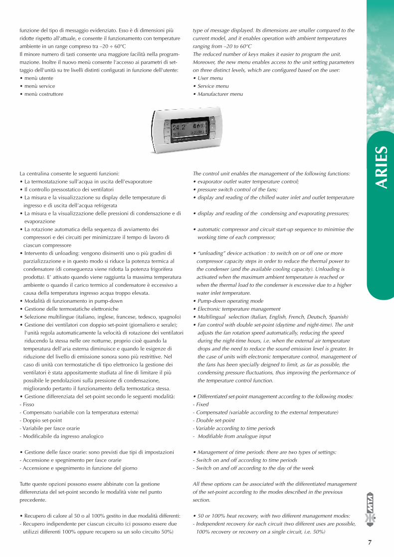
The new semigraphic and backlighted LCD, denominated PGD, has
been specially designed for pCO controls and consists of a 4-line x
20-character display (standard mode). Of the 6 pushbutton LEDs, 4 are
always illuminated, while the other 2 (alarm and operation buttons)
light up when selected. The height of the character varies based on the
11. Struttura e cofanatura
Tutto il basamento, i pannelli di tamponamento sono realizzati con
lamiera di acciaio al carbonio zincata ed uniti tra loro con rivetti di
acciaio zincato. Tutte le lamiere sono sottoposte ad un trattamento di
fosfosgrassaggio e verniciatura con polveri poliesteri. I montanti dell'u-
nità sono costituiti da profili in alluminio. La struttura è stata studiata
per accedere facilmente a tutti i componenti del refrigeratore.
Il colore della base è blu RAL 5013 bucciato. Il colore del resto della
struttura, della cofanatura e delle rete di protezione è grigio chiaro RAL
7035 bucciato.
Optional:
• supporti antivibranti
12. Quadro elettrico di potenza e controllo
E’ realizzato in conformità alle norme EN 60204-1. Garantisce la
protezione contro gli agenti atmosferici (IP54) necessaria per l’installa-
zione del refrigeratore all’esterno. Viene utilizzata componentistica di
primaria marca. La sezione di potenza comprende interruttori automa-
tici per la protezione dei compressori; la sezione di controllo com-
prende il trasformatore per l’alimentazione degli ausiliari e le schede a
microprocessore. I quadri elettrici sono dotati di dispositivo di interrut-
tore-sezionatore generale blocco-porta, dispositivo blocco-porta a scat-
to e tasca portadocumenti. Per i ventilatori è previsto un interruttore
termico. L’alimentazione elettrica è 400/3/50.
Optional:
• Relé di minima/massima tensione (tolleranza +/- 10%) e rotazione
fasi non corretta;
• Condensatore di rifasamento (cosØ= 0,92);
13. Kit idronico
I refrigeratori d’acqua Aries possono essere forniti, in opzione, con
serbatoio di accumulo inerziale e pompa assemblati su di un unico
basamento (gruppo idronico). Il serbatoio di accumulo è cilindrico
orizzontale in acciaio al carbonio e di adeguata capacità. E’ rivestito
esternamente da un materassino isolante anticondensa con finitura
alluminata. Le pompe P2 o P3 consistono in pompe di circa 2 bar di
prevalenza utile (P2), oppure di circa 3 bar di prevalenza utile (P3). La
pompa è installata all’interno del vano condensatori ed è già collegata
all’evaporatore ed ai punti d’ingresso ed uscita acqua tramite tubazioni
flessibili. Un rubinetto in aspirazione ed uno in mandata consentono
di isolare la pompa in caso di manutenzione. Le pompe sono
controllate dalla centralina di controllo pCO2 che gestisce l’allarme
della protezione termica.
Optional:
• Resistenza antigelo evaporatore e pompa;
• Resistenza antigelo evaporatore, serbatoio e pompa.
14. Controllo e gestione
Il nuovo display LCD, semigrafico e retroilluminato, denominato PGD, è
stato studiato appositamente per i controlli pCO ed è composto da un
display di 4 righe per 20 caratteri (in modalità std). Dei 6 pulsanti led, 4
sono sempre illuminati mentre gli altri 2 (tasto allarme + funzionamento)
si illuminano se selezionati. L'altezza del carattere risulta variabile in
6
®
EASYY000BD_V 07-04-2006 12.13 Pagina 6
AR
IES
funzione del tipo di messaggio evidenziato. Esso è di dimensioni più
ridotte rispetto all'attuale, e consente il funzionamento con temperature
ambiente in un range compreso tra –20 ÷ 60°C
Il minore numero di tasti consente una maggiore facilità nella program-
mazione. Inoltre il nuovo menù consente l'accesso ai parametri di set-
taggio dell'unità su tre livelli distinti configurati in funzione dell'utente:
• menù utente
• menù service
• menù costruttore
La centralina consente le seguenti funzioni:
• La termostatazione sull’acqua in uscita dell’evaporatore
• Il controllo pressostatico dei ventilatori
• La misura e la visualizzazione su display delle temperature di
ingresso e di uscita dell’acqua refrigerata
• La misura e la visualizzazione delle pressioni di condensazione e di
evaporazione
• La rotazione automatica della sequenza di avviamento dei
compressori e dei circuiti per minimizzare il tempo di lavoro di
ciascun compressore
• Intervento di unloading: vengono disinseriti uno o più gradini di
parzializzazione e in questo modo si riduce la potenza termica al
condensatore (di conseguenza viene ridotta la potenza frigorifera
prodotta). E’ attivato quando viene raggiunta la massima temperatura
ambiente o quando il carico termico al condensatore è eccessivo a
causa della temperatura ingresso acqua troppo elevata.
• Modalità di funzionamento in pump-down
• Gestione delle termostatiche elettroniche
• Selezione multilingue (italiano, inglese, francese, tedesco, spagnolo)
• Gestione dei ventilatori con doppio set-point (giornaliero e serale);
l'unità regola automaticamente la velocità di rotazione dei ventilatori
riducendo la stessa nelle ore notturne, proprio cioè quando la
temperatura dell'aria esterna diminuisce e quando le esigenze di
riduzione del livello di emissione sonora sono più restrittive. Nel
caso di unità con termostatiche di tipo elettronico la gestione dei
ventilatori è stata appositamente studiata al fine di limitare il più
possibile le pendolazioni sulla pressione di condensazione,
migliorando pertanto il funzionamento della termostatica stessa.
• Gestione differenziata del set-point secondo le seguenti modalità:
- Fisso
- Compensato (variabile con la temperatura esterna)
- Doppio set-point
- Variabile per fasce orarie
- Modificabile da ingresso analogico
• Gestione delle fasce orarie: sono previsti due tipi di impostazioni
- Accensione e spegnimento per fasce orarie
- Accensione e spegnimento in funzione del giorno
Tutte queste opzioni possono essere abbinate con la gestione
differenziata del set-point secondo le modalità viste nel punto
precedente.
• Recupero di calore al 50 o al 100% gestito in due modalità differenti:
- Recupero indipendente per ciascun circuito (ci possono essere due
utilizzi differenti 100% oppure recupero su un solo circuito 50%)
type of message displayed. Its dimensions are smaller compared to the
current model, and it enables operation with ambient temperatures
ranging from –20 to 60°C
The reduced number of keys makes it easier to program the unit.
Moreover, the new menu enables access to the unit setting parameters
on three distinct levels, which are configured based on the user:
• User menu
• Service menu
• Manufacturer menu
The control unit enables the management of the following functions:
• evaporator outlet water temperature control;
• pressure switch control of the fans;
• display and reading of the chilled water inlet and outlet temperature
• display and reading of the condensing and evaporating pressures;
• automatic compressor and circuit start-up sequence to minimise the
working time of each compressor;
• “unloading” device activation : to switch on or off one or more
compressor capacity steps in order to reduce the thermal power to
the condenser (and the available cooling capacity). Unloading is
activated when the maximum ambient temperature is reached or
when the thermal load to the condenser is excessive due to a higher
water inlet temperature.
• Pump-down operating mode
• Electronic temperature management
• Multilingual selection (Italian, English, French, Deutsch, Spanish)
• Fan control with double set-point (daytime and night-time). The unit
adjusts the fan rotation speed automatically, reducing the speed
during the night-time hours, i.e. when the external air temperature
drops and the need to reduce the sound emission level is greater. In
the case of units with electronic temperature control, management of
the fans has been specially deigned to limit, as far as possible, the
condensing pressure fluctuations, thus improving the performance of
the temperature control function.
• Differentiated set-point management according to the following modes:
- Fixed
- Compensated (variable according to the external temperature)
- Double set-point
- Variable according to time periods
- Modifiable from analogue input
• Management of time periods: there are two types of settings:
- Switch on and off according to time periods
- Switch on and off according to the day of the week
All these options can be associated with the differentiated management
of the set-point according to the modes described in the previous
section.
• 50 or 100% heat recovery, with two different management modes:
- Independent recovery for each circuit (two different uses are possible,
100% recovery or recovery on a single circuit, i.e. 50%)
7
®
EASYY000BD_V 07-04-2006 12.13 Pagina 7
AR
IES
- 100% heat recovery: this mode requires the presence of a common
manifold for both heat regenerators. In this case, two recovery steps
are available for use.
Please remember that, in both cases, the operating priority for the unit
is always in cooling mode; therefore, it could happen that the request
for heat recovery is ignored once the machine has satisfied the request
in cooling mode (because the set point for the water temperature to the
evaporator has been reached).
• Management of the heating elements: if the ambient temperature
drops below a set value, the anti-freeze heaters are switched on. A
programmable parameter can be set in order to automatically enable
or disable the operation of the anti-freeze heaters.
• Alarm history display
• Stand-by pump operation: in case of failure of the main pump the
unit operates using the second pump and an alarm is displayed. It is
also possible to alternate automatically the pumps in order to
balance the number of working hours of each pump, without
stopping the unit.
• Serial interface
• Remote connection via GSM network
• Working hours of the chiller and each compressor with time over run
signal for maintenance
• It manages separate and variable alarms according to the machine
configuration, including:
1. high condensing pressure;
2. low evaporating pressure;
3. anti-freeze alarm on water outlet from evaporator;
4. compressor, fan and pump failure;
5. insufficient water flow through the evaporator (with differential
pressure switch or flow switch);
6. high water inlet and outlet temperature; pressure switch or flow
switch);
A voltage-free contact is then available for a remote general alarm.
Options:
• a simple remote control kit comprising plastic box with 3 meters of
cable, an on/off selector, a green led for operation and a red led for
general alarm.
• Serial connection:
It allows local supervision through a personal computer or via
connection of one or more machines to a BMS. The cable connecting
the machines to the supervision system must be provided by the
customer. Connection to the following systems can be made by adding
the specified items to the serial equipment:
- Carel RS485 serial communication interface
- Modbus RS485 serial communication interface
- Serial communication interface: LonWorks RS485 or FTT-10A
- BACNET serial communication interface
- GSM serial communication interface: using a GSM modem, this
application enables the transmission and reception of SMS messages
to signal alarms or modify the parameters managed via serial
connection.
NOTE: for technical details, please refer to the manuals pertaining to
the relevant supervision kits
The management and control software must be provided by the customer.
- Recupero di calore al 100%: è la situazione che prevede un
collettore comune per entrambi i recuperatori. In questo caso si
possono avere due gradini di recupero per l'utilizzo.
Si ricorda che in tutti e due i casi la priorità di funzionamento
dell'unità è sempre sull'utilizzo freddo; pertanto può succedere che la
richiesta di recupero di calore venga ignorata qualora la macchina
abbia soddisfatto la richiesta in freddo (perché si è raggiunto il set
impostato sulla temperatura dell'acqua all'evaporatore).
• Gestione delle resistenze riscaldanti: qualora la temperatura ambiente
scenda al di sotto di un valore impostato, interviene l'accensione
delle resistenze antigelo. È possibile impostare un parametro
programmabile che permette in automatico il funzionamento o meno
della stessa.
• Visualizzazione dello storico allarmi
• Gestione pompa in stand-by (in caso di anomalia nel funzionamento
di una pompa, la macchina non si blocca, ma viene immediatamente
alimentata la seconda pompa, con relativa segnalazione
dell’anomalia; inoltre è possibile mediante un parametro
programmabile, l’avvicendamento automatico delle pompe per
equalizzare il numero di ore di funzionamento. L’avvicendamento è
possibile senza blocco nel funzionamento della macchina).
• Interfaccia seriale
• Collegamento remoto mediante rete GSM
• Il conteggio delle ore di funzionamento dei chiller e dei singoli
compressori con segnalazione del superamento del numero di ore
programmato per la manutenzione.
• Gestisce allarmi separati e variabili a seconda della configurazione
della macchina, tra i quali:
1. allarme alta pressione condensazione;
2. allarme bassa pressione evaporazione;
3. allarme antigelo sull’acqua in uscita dall’evaporatore;
4. allarme per guasto compressore, ventilatori ed eventuale pompa;
5. allarme per insufficiente passaggio acqua attraverso l’evaporatore
(con pressostato differenziale acqua o flussostato);
6. allarme alta temperatura ingresso e uscita acqua;
E’ disponibile, inoltre, un contatto pulito per portare a distanza la
segnalazione di un allarme generale.
Optional:
• Kit controllo remoto semplice della macchina costituito da una
scatola in plastica con 3 metri di cavo, un pulsante di on/off, un LED
verde di consenso e un LED rosso di allarme generale
• Predisposizione per collegamento seriale:
Consente la supervisione locale con un personal computer o attraverso
il collegamento ad un BMS di una o più macchine. Il cavo di
collegamento tra le macchine e il sistema di supervisione è a carico
del cliente. E’ possibile il collegamento ai seguenti sistemi,
aggiungendo alla predisposizione seriale quanto specificato:
- Interfaccia seriale di comunicazione Carel RS485
- Interfaccia seriale di comunicazione Modbus RS485
- Interfaccia seriale di comunicazione: LonWorks RS485 o FTT-10A
- Interfaccia seriale di comunicazione BACNET
- Interfaccia seriale di comunicazione GSM: L’applicativo permette, uti-
lizzando un modem GSM, l’invio e la ricezione di messaggi SMS per
la segnalazione di allarmi o per variazione di parametri gestiti via
seriale.
NOTA: per i dettagli tecnici si rimanda al manuale dei relativi kit di
supervisione
Il software per la gestione ed il controllo sono a cura del cliente.
8
®
EASYY000BD_V 07-04-2006 12.13 Pagina 8
AR
IES
9
®
Guida alla selezione
La selezione di un refrigeratore viene eseguita tramite la tabella
“Guida alla selezione” e tramite le Tabelle Dati relative a ciascuna
singola macchina. Per una corretta selezione di un refrigeratore è
necessario, inoltre:
1) Verificare che siano rispettati i limiti di funzionamento indicati
nella tabella “Limiti di funzionamento”;
2) Verificare che la portata d’acqua da raffreddare sia compresa tra i
valori di portata minima e massima indicati nella tabella
“Dati generali” di ciascuna macchina; valori di portata troppo bassa
comportano un flusso laminare e di conseguenza, pericolo di
ghiacciamento ed una cattiva regolazione; al contrario valori di
portata troppo elevati comportano eccessive perdite di carico e
possibilità di rottura dei tubi dell’evaporatore;
3) Prevedere l’aggiunta di glicole etilenico o di altri liquidi anticonge-
lanti per utilizzi del refrigeratore al di sotto di 2°C; consultare la
tabella “Soluzioni di acqua e glicole etilenico” per determinare la
quantità di glicole etilenico necessaria e per valutare la riduzione di
resa frigorifera, l’aumento di potenza assorbita dai compressori,
l’aumento delle perdite di carico all’evaporatore a causa della
presenza del glicole etilenico;
4) Qualora il refrigeratore venga installato ad una altitudine maggiore
di 500 m. valutare la riduzione di resa frigorifera e l’aumento di
potenza assorbita dal compressore tramite i coefficienti indicati nella
tabella “Coefficienti correttivi condensatore”;
5) Qualora la differenza di temperatura fra ingresso e uscita acqua sia
diversa da 5°C correggere la potenza frigorifera e la potenza
assorbita utilizzando la tabella “coefficienti correttivi ∆T ≠ 5°C”
Selection guide
For chiller selecting use the table “Selection guide” and the table
“Performance data” relative to each unit. For a correct chiller selection
it is also necessary:
1) Check the operational limits as indicated in the chart “Operating
limits”;
2) Verify that the cool water flow is between the minim and maximum
values of water flow which are described in the “General Data”
table. A very low flow can cause laminar flow and thus danger of ice
formation and wil cause poor unit control. A very high flow can
cause greater pressure drops and the possibility of tube failure inside
the evaporator;
3) For working temperatures under 2°C it is necessary to add ethylene
glycol or some other antifreeze liquids.Consult the chart “Solutions
of water and glycol” to determine the necessary quantity of ethylene
glycol, the reduction of cooling capacity, the increase of power
absorbed by the compressors, the increase of evaporator pressure
drop due to the presence of the ethylene glycol;
4) If the chiller is to be installed at an altitude higher than 500 m, you
must calculate the cooling capacity reduction and the increase of
compressor absorbed power by checking the coefficients as shown
in the chart “Condenser correction factors”;
5) When the difference in temperature between water inlet and outlet
is different from 5°C, the cooling capacity and the absorbed power
must be connected using the table “correction factors ∆T ≠ 5°C.”
EASYY000BD_V 07-04-2006 12.14 Pagina 9
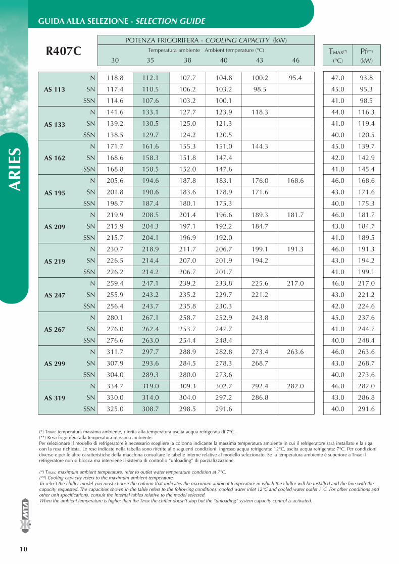
POTENZA FRIGORIFERA - COOLING CAPACITY (kW)Temperatura ambiente Ambient temperature (°C)
30 35 38 40 43 46
GUIDA ALLA SELEZIONE - SELECTION GUIDEA
RIE
S
10
®
TMAX(*) Pf(**)
(°C) (kW)R407C
N 118.8 112.1 107.7 104.8 100.2 95.4
SN 117.4 110.5 106.2 103.2 98.5
SSN 114.6 107.6 103.2 100.1
N 141.6 133.1 127.7 123.9 118.3
SN 139.2 130.5 125.0 121.3
SSN 138.5 129.7 124.2 120.5
N 171.7 161.6 155.3 151.0 144.3
SN 168.6 158.3 151.8 147.4
SSN 168.8 158.5 152.0 147.6
N 205.6 194.6 187.8 183.1 176.0 168.6
SN 201.8 190.6 183.6 178.9 171.6
SSN 198.7 187.4 180.1 175.3
N 219.9 208.5 201.4 196.6 189.3 181.7
SN 215.9 204.3 197.1 192.2 184.7
SSN 215.7 204.1 196.9 192.0
N 230.7 218.9 211.7 206.7 199.1 191.3
SN 226.5 214.4 207.0 201.9 194.2
SSN 226.2 214.2 206.7 201.7
N 259.4 247.1 239.2 233.8 225.6 217.0
SN 255.9 243.2 235.2 229.7 221.2
SSN 256.4 243.7 235.8 230.3
N 280.1 267.1 258.7 252.9 243.8
SN 276.0 262.4 253.7 247.7
SSN 276.6 263.0 254.4 248.4
N 311.7 297.7 288.9 282.8 273.4 263.6
SN 307.9 293.6 284.5 278.3 268.7
SSN 304.0 289.3 280.0 273.6
N 334.7 319.0 309.3 302.7 292.4 282.0
SN 330.0 314.0 304.0 297.2 286.8
SSN 325.0 308.7 298.5 291.6
(*) Tmax: temperatura massima ambiente, riferita alla temperatura uscita acqua refrigerata di 7°C.(**) Resa frigorifera alla temperatura massima ambiente.Per selezionare il modello di refrigeratore è necessario scegliere la colonna indicante la massima temperatura ambiente in cui il refrigeratore sarà installato e la rigacon la resa richiesta. Le rese indicate nella tabella sono riferite alle seguenti condizioni: ingresso acqua refrigerata: 12°C, uscita acqua refrigerata: 7°C. Per condizionidiverse e per le altre caratteristiche della macchina consultare le tabelle interne relative al modello selezionato. Se la temperatura ambiente è superiore a Tmax il refrigeratore non si blocca ma interviene il sistema di controllo “unloading” di parzializzazione.
(*) Tmax: maximum ambient temperature, refer to outlet water temperature condition at 7°C.(**) Cooling capacity refers to the maximum ambient temperature.To select the chiller model you must choose the column that indicates the maximum ambient temperature in which the chiller will be installed and the line with thecapacity requested. The capacities shown in the table refers to the following conditions: cooled water inlet 12°C and cooled water outlet 7°C. For other conditions andother unit specifications, consult the internal tables relative to the model selected.When the ambient temperature is higher than the Tmax the chiller doesn’t stop but the “unloading” system capacity control is activated.
47.0 93.8
45.0 95.3
41.0 98.5
44.0 116.3
41.0 119.4
40.0 120.5
45.0 139.7
42.0 142.9
41.0 145.4
46.0 168.6
43.0 171.6
40.0 175.3
46.0 181.7
43.0 184.7
41.0 189.5
46.0 191.3
43.0 194.2
41.0 199.1
46.0 217.0
43.0 221.2
42.0 224.6
45.0 237.6
41.0 244.7
40.0 248.4
46.0 263.6
43.0 268.7
40.0 273.6
46.0 282.0
43.0 286.8
40.0 291.6
AS 113
AS 133
AS 162
AS 195
AS 209
AS 219
AS 247
AS 267
AS 299
AS 319
EASYY000BD_V 07-04-2006 12.14 Pagina 10
®
AR
IES
11
Conditioning the air, releasing new opportunities.
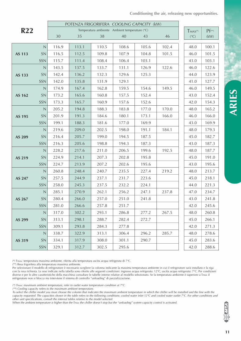
POTENZA FRIGORIFERA COOLING CAPACITY (kW)Temperatura ambiente Ambient temperature (°C)
30 35 38 40 43 46TMAX(*) Pf(**)
(°C) (kW)R22
N 116.9 113.1 110.5 108.6 105.6 102.4
SN 116.5 112.5 109.8 107.9 104.8 101.5
SSN 115.7 111.4 108.4 106.4 103.1
N 143.5 137.5 133.7 131.1 126.9 122.6
SN 142.4 136.2 132.3 129.6 125.3
SSN 142.0 135.8 131.9 129.1
N 174.9 167.4 162.8 159.5 154.6 149.5
SN 173.2 165.6 160.8 157.5 152.4
SSN 173.3 165.7 160.9 157.6 152.6
N 205.2 194.8 188.3 183.8 177.0 170.0
SN 201.9 191.3 184.6 180.1 173.1 166.0
SSN 199.1 188.3 181.6 177.0 169.9
N 219.6 209.0 202.5 198.0 191.1 184.1
SN 216.4 205.7 199.0 194.5 187.5
SSN 216.3 205.6 198.8 194.3 187.3
N 228.2 217.6 211.0 206.5 199.6 192.5
SN 224.9 214.1 207.3 202.8 195.8
SSN 224.7 213.9 207.2 202.6 195.6
N 260.8 248.4 240.7 235.5 227.4 219.2
SN 257.5 244.9 237.1 231.7 223.6
SSN 258.0 245.3 237.5 232.2 224.1
N 285.1 270.9 262.1 256.2 247.1 237.8
SN 280.4 266.0 257.0 251.0 241.8
SSN 281.0 266.6 257.8 251.7
N 317.0 302.2 293.1 286.8 277.2 267.5
SN 313.1 298.1 288.7 282.4 272.7
SSN 309.1 293.8 284.3 277.8
N 338.7 322.9 313.1 306.4 296.2 285.7
SN 334.1 317.9 308.0 301.1 290.7
SSN 329.1 312.7 302.5 295.6
(*) Tmax: temperatura massima ambiente, riferita alla temperatura uscita acqua refrigerata di 7°C.(**) Resa frigorifera alla temperatura massima ambiente.Per selezionare il modello di refrigeratore è necessario scegliere la colonna indicante la massima temperatura ambiente in cui il refrigeratore sarà installato e la rigacon la resa richiesta. Le rese indicate nella tabella sono riferite alle seguenti condizioni: ingresso acqua refrigerata: 12°C, uscita acqua refrigerata: 7°C. Per condizionidiverse e per le altre caratteristiche della macchina consultare le tabelle interne relative al modello selezionato. Se la temperatura ambiente è superiore a Tmax il refrigeratore non si blocca ma interviene il sistema di controllo “unloading” di parzializzazione.
(*) Tmax: maximum ambient temperature, refer to outlet water temperature condition at 7°C.(**) Cooling capacity refers to the maximum ambient temperature.To select the chiller model you must choose the column that indicates the maximum ambient temperature in which the chiller will be installed and the line with thecapacity requested. The capacities shown in the table refers to the following conditions: cooled water inlet 12°C and cooled water outlet 7°C. For other conditions andother unit specifications, consult the internal tables relative to the model selected.When the ambient temperature is higher than the Tmax the chiller doesn’t stop but the “unloading” system capacity control is activated.
48.0 100.1
46.0 101.5
43.0 103.1
46.0 122.6
44.0 123.9
41.0 127.7
46.0 149.5
43.0 152.4
42.0 154.3
48.0 165.2
46.0 166.0
43.0 169.9
48.0 179.3
45.0 182.7
43.0 187.3
48.0 187.7
45.0 191.0
43.0 195.6
48.0 213.7
45.0 218.1
44.0 221.3
47.0 234.7
43.0 241.8
42.0 245.6
48.0 260.8
45.0 266.1
42.0 271.3
48.0 278.6
45.0 283.6
42.0 288.6
AS 113
AS 133
AS 162
AS 195
AS 209
AS 219
AS 247
AS 267
AS 299
AS 319
EASYY000BD_V 07-04-2006 12.14 Pagina 11
Portata acqua Water flow rate m3/h
Prevalenza disponibile P2 Available head pressure P2 bar
Prevalenza disponibile P3 Available head pressure P3 bar
Potenza nominale P2 Nominal power P2 kW
Potenza nominale P3 Nominal power P3 kW
Volume serbatoio Tank volume l
N
SN
SSN
N
SN
SSN
N SN SSN
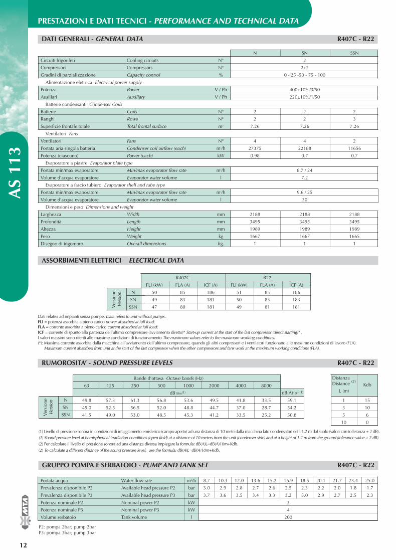
Circuiti frigoriferi Cooling circuits N° 2
Compressori Compressors N° 2+2
Gradini di parzializzazione Capacity control % 0 - 25 -50 - 75 - 100
Alimentazione elettrica Electrical power supply
Potenza Power V / Ph 400±10%/3/50
Ausiliari Auxiliary V / Ph 220±10%/1/50
Batterie condensanti Condenser Coils
Batterie Coils N° 2 2 2
Ranghi Rows N° 2 2 3
Superficie frontale totale Total frontal surface m2 7.26 7.26 7.26
Ventilatori Fans
Ventilatori Fans N° 4 4 2
Portata aria singola batteria Condenser coil airflow (each) m3/h 27375 22188 11656
Potenza (ciascuno) Power (each) kW 0.98 0.7 0.7
Evaporatore a piastre Evaporator plate type
Portata min/max evaporatore Min/max evaporator flow rate m3/h 8.7 / 24
Volume d’acqua evaporatore Evaporator water volume l 7.2
Evaporatore a fascio tubiero Evaporator shell and tube type
Portata min/max evaporatore Min/max evaporator flow rate m3/h 9.6 / 25
Volume d’acqua evaporatore Evaporator water volume l 30
Dimensioni e peso Dimensions and weight
Larghezza Width mm 2188 2188 2188
Profondità Length mm 3495 3495 3495
Altezza Height mm 1989 1989 1989
Peso Weight kg 1667 1667 1665
Disegno di ingombro Overall dimensions fig. 1 1 1
PRESTAZIONI E DATI TECNICI - PERFORMANCE AND TECHNICAL DATA A
S 11
3
12
®
DATI GENERALI - GENERAL DATA R407C - R22
ASSORBIMENTI ELETTRICI ELECTRICAL DATA
R407C R22
FLI (kW) FLA (A) ICF (A) FLI (kW) FLA (A) ICF (A)
50 85 186 51 85 186
49 83 183 50 83 183
47 80 181 49 81 181Ver
sion
eV
ersi
on
Dati relativi ad impianti senza pompe. Data refers to unit without pumps.FLI = potenza assorbita a pieno carico power absorbed at full load; FLA = corrente assorbita a pieno carico current absorbed at full load;ICF = corrente di spunto alla partenza dell’ultimo compressore (avviamento diretto)* Start-up current at the start of the last compressor (direct starting)* . I valori massimi sono riferiti alle massime condizioni di funzionamento The maximum values refer to the maximum working conditions.(*): Massima corrente assorbita dalla macchina all’avviamento dell’ultimo compressore, quando gli altri compressori e i ventilatori funzionano alle massime condizioni di lavoro (FLA).
Maximum current absorbed from unit at the start of the last compressor when the other compressors and fans work at the maximum working conditions (FLA).
RUMOROSITA’ - SOUND PRESSURE LEVELS R407C - R22
Bande d’ottava Octave bands (Hz)
63 125 250 500 1000 2000 4000 8000
dB10m(1)
49.8 57.3 61.3 56.8 53.6 49.5 41.8 33.5 59.1
45.0 52.5 56.5 52.0 48.8 44.7 37.0 28.7 54.2
41.5 49.0 53.0 48.5 45.3 41.2 33.5 25.2 50.8Ver
sion
eV
ersi
on
dB(A)10m(1)
1 15
3 10
5 6
10 0
DistanzaDistance (2)
L (m)Kdb
(1) Livello di pressione sonora in condizioni di irraggiamento emisferico (campo aperto) ad una distanza di 10 metri dalla macchina lato condensatori ed a 1.2 m dal suolo (valori con tolleranza ± 2 dB). (1) Sound pressure level at hemispherical irradiation conditions (open field) at a distance of 10 meters from the unit (condenser side) and at a height of 1.2 m from the ground (tolerance value ± 2 dB). (2) Per calcolare il livello di pressione sonora ad una distanza diversa impiegare la formula: dB(A)L=dB(A)10m+Kdb. (2) To calculate a different distance of the sound pressure level, use the formula: dB(A)L=dB(A)10m+Kdb.
GRUPPO POMPA E SERBATOIO - PUMP AND TANK SET R407C - R22
8.7 10.3 12.0 13.6 15.2 16.9 18.5 20.1 21.7 23.4 25.0
3.0 2.9 2.8 2.7 2.6 2.5 2.3 2.2 2.0 1.8 1.7
3.7 3.6 3.5 3.4 3.3 3.2 3.0 2.9 2.7 2.5 2.3
3
4
200
P2: pompa 2bar; pump 2barP3: pompa 3bar; pump 3bar
EASYY000BD_V 07-04-2006 12.14 Pagina 12

®
AS
113
13
Conditioning the air, releasing new opportunities.
PRESTAZIONI - PERFORMANCE DATA
R407C
56
SSN 789
10
56
SN 789
10
56
N 789
10
Temperatura ambiente Ta °C Ambient temperature Ta °C30 35 38 40 43 46
Pf Pa Fw Pf Pa Fw Pf Pa Fw Pf Pa Fw Pf Pa Fw Pf Pa Fwtu (°C) (kW) (kW) (m3/h) (kW) (kW) (m3/h) (kW) (kW) (m3/h) (kW) (kW) (m3/h) (kW) (kW) (m3/h) (kW) (kW) (m3/h)
110.7 31.5 19.0 104.4 35.1 17.9 100.3 37.5 17.3 97.5 39.2 16.8 93.2 42.0 16.0 88.8 44.9 15.3114.7 31.8 19.7 108.2 35.5 18.6 104.0 37.9 17.9 101.1 39.6 17.4 96.7 42.3 16.6 92.1 45.3 15.8118.8 32.2 20.4 112.1 35.8 19.3 107.7 38.3 18.5 104.8 40.0 18.0 100.2 42.8 17.2 95.4 45.7 16.4123.0 32.5 21.2 116.0 36.3 20.0 111.6 38.7 19.2 108.5 40.4 18.7 103.8 43.2 17.9 98.9 46.1 17.0127.3 32.9 21.9 120.1 36.6 20.7 115.5 39.1 19.9 112.4 40.8 19.3 107.5 43.6 18.5 102.4 46.5 17.6131.7 33.3 22.6 124.2 37.0 21.4 119.5 39.5 20.6 116.2 41.2 20.0 111.2 44.0 19.1 106.0 47.0 18.2
109.5 33.0 18.8 103.0 36.8 17.7 98.9 39.3 17.0 96.1 41.1 16.5 91.7 43.9 15.8 87.2 46.9 15.0113.4 33.4 19.5 106.7 37.2 18.4 102.5 39.7 17.6 99.6 41.5 17.1 95.1 44.4 16.4 90.4 47.4 15.5117.4 33.8 20.2 110.5 37.6 19.0 106.2 40.2 18.3 103.2 42.0 17.7 98.5 44.8 16.9121.5 34.2 20.9 114.4 38.1 19.7 109.9 40.6 18.9 106.8 42.4 18.4 102.0 45.3 17.5125.7 34.6 21.6 118.4 38.5 20.4 113.7 41.1 19.6 110.5 42.9 19.0 105.6 45.8 18.2130.0 35.1 22.4 122.4 39.0 21.1 117.6 41.5 20.2 114.3 43.4 19.7 109.2 46.2 18.8
T max.(**)(°C)
46.046.045.045.044.044.0
42.042.041.041.040.039.0
tu: temperatura acqua uscita evaporatore evaporator outlet water temperature;Pf: potenza frigorifera cooling capacity; Pa: potenza assorbita dai compressori power absorbed by the compressors;Fw: portata d’acqua (∆t = 5°C) water flow rate (∆t = 5°C).É permessa l’interpolazione dei valori ma non la loro estrapolazione. Interpolation is allowed, extrapolation is not permitted.Per la determinazione di Pf, Pa e Fw per ∆t diversi da 5°C vedere la tabella ”Coefficienti correttivi per ∆t diversi da 5°C”. To calculate Pf, Pa and Fw for ∆t ≠ 5°C when examiningthe table ”Correction factors for ∆t ≠ 5°C”.(**): Temperatura massima ambiente. Se la temperatura ambiente è superiore a T max. il refrigeratore non si blocca ma interviene il sistema “unloading” di parzializzazione.
Maximum ambient temperature. When the ambient temperature is higher than the T max. the chiller doesn’t stop but the “unloading” system capacity control is activated.
48.048.047.047.046.046.0
107.0 36.1 18.4 100.3 40.2 17.3 96.1 42.9 16.5 93.2 44.8 16.0110.8 36.6 19.1 103.9 40.7 17.9 99.5 43.4 17.1 96.5 45.3 16.6114.6 37.1 19.7 107.6 41.2 18.5 103.2 44.0 17.7 100.1 45.8 17.2118.7 37.6 20.4 111.3 41.8 19.1 106.7 44.5 18.4 103.5 46.5 17.8122.7 38.1 21.1 115.1 42.3 19.8 110.3 45.1 19.0 107.0 47.0 18.4126.8 38.7 21.8 118.9 42.9 20.5 114.0 45.6 19.6
R22
56
SSN 789
10
56
SN 789
10
56
N 789
10
Temperatura ambiente Ta °C Ambient temperature Ta °C30 35 38 40 43 46
Pf Pa Fw Pf Pa Fw Pf Pa Fw Pf Pa Fw Pf Pa Fw Pf Pa Fwtu (°C) (kW) (kW) (m3/h) (kW) (kW) (m3/h) (kW) (kW) (m3/h) (kW) (kW) (m3/h) (kW) (kW) (m3/h) (kW) (kW) (m3/h)
109.1 30.0 18.8 105.3 33.5 18.1 102.8 35.8 17.7 101.0 37.4 17.4 98.1 40.0 16.9 94.9 42.7 16.3113.0 30.3 19.4 109.2 33.8 18.8 106.6 36.1 18.3 104.7 37.8 18.0 101.8 40.4 17.5 98.6 43.1 17.0116.9 30.6 20.1 113.1 34.1 19.4 110.5 36.5 19.0 108.6 38.1 18.7 105.6 40.7 18.2 102.4 43.5 17.6121.0 30.9 20.8 117.1 34.5 20.1 114.4 36.8 19.7 112.5 38.5 19.4 109.5 41.1 18.8 106.3 43.8 18.3125.1 31.2 21.5 121.2 34.8 20.8 118.5 37.2 20.4 116.6 38.8 20.1 113.6 41.4 19.5 110.3 44.2 19.0129.4 31.5 22.3 125.4 35.1 21.6 122.7 37.5 21.1 120.8 39.2 20.8 117.7 41.8 20.2 114.3 44.6 19.7
108.7 31.4 18.7 104.8 35.1 18.0 102.2 37.5 17.6 100.3 39.2 17.3 97.3 41.8 16.7 94.1 44.6 16.2112.6 31.8 19.4 108.6 35.4 18.7 106.0 37.9 18.2 104.1 39.6 17.9 101.0 42.2 17.4 97.8 45.1 16.8116.5 32.1 20.0 112.5 35.8 19.4 109.8 38.2 18.9 107.9 40.0 18.6 104.8 42.6 18.0 101.5 45.5 17.5120.6 32.5 20.7 116.5 36.2 20.0 113.8 38.7 19.6 111.8 40.4 19.2 108.7 43.1 18.7124.7 32.8 21.5 120.6 36.6 20.7 117.9 39.1 20.3 115.9 40.8 19.9 112.7 43.5 19.4129.0 33.2 22.2 124.8 37.0 21.5 122.0 39.5 21.0 120.0 41.2 20.6 116.8 44.0 20.1
T max.(**)(°C)
47.047.046.045.045.044.0
44.044.043.042.041.041.0
49.049.048.048.047.047.0
107.9 34.3 18.6 103.8 38.3 17.8 101.0 40.9 17.4 98.9 42.7 17.0 95.7 45.5 16.5111.7 34.8 19.2 107.5 38.8 18.5 104.7 41.4 18.0 102.6 43.2 17.6 99.4 46.1 17.1115.7 35.3 19.9 111.4 39.3 19.2 108.4 41.9 18.7 106.4 43.8 18.3 103.1 46.6 17.7119.7 35.7 20.6 115.4 39.8 19.8 112.4 42.5 19.3 110.3 44.3 19.0123.8 36.2 21.3 119.3 40.4 20.5 116.4 43.0 20.0 114.3 44.9 19.7128.1 36.8 22.0 123.5 40.9 21.2 120.5 43.6 20.7 118.3 45.5 20.4
EASYY000BD_V 07-04-2006 12.14 Pagina 13

N
SN
SSN
N SN SSN
Circuiti frigoriferi Cooling circuits N° 2
Compressori Compressors N° 2+2
Gradini di parzializzazione Capacity control % 0 - 25 - 50 - 75 - 100
Alimentazione elettrica Electrical power supply
Potenza Power V / Ph 400±10%/3/50
Ausiliari Auxiliary V / Ph 220±10%/1/50
Batterie condensanti Condenser Coils
Batterie Coils N° 2 2 2
Ranghi Rows N° 2 2 3
Superficie frontale totale Total frontal surface m2 7.26 7.26 7.26
Ventilatori Fans N° 4 4 2
Portata aria singola batteria Condenser coil airflow (each) m3/h 27375 22188 14508
Potenza (ciascuno) Power (each) kW 0.98 0.7 0.7
Evaporatore a piastre Evaporator plate type
Portata min/max evaporatore Min/max evaporator flow rate m3/h 10.4 / 28.5
Volume d’acqua evaporatore Evaporator water volume l 8.8
Evaporatore a fascio tubiero Evaporator shell and tube type
Portata min/max evaporatore Min/max evaporator flow rate m3/h 11.4 / 28
Volume d’acqua evaporatore Evaporator water volume l 35.2
Dimensioni e peso Dimensions and weight
Larghezza Width mm 2188 2188 2188
Profondità Length mm 3495 3495 3495
Altezza Height mm 1989 1989 1989
Peso Weight kg 1724 1724 1746
Disegno di ingombro Overall dimensions fig. 1 1 1
PRESTAZIONI E DATI TECNICI - PERFORMANCE AND TECHNICAL DATA A
S 13
3
14
®
DATI GENERALI - GENERAL DATA R407C - R22
ASSORBIMENTI ELETTRICI ELECTRICAL DATA
R407C R22
FLI (kW) FLA (A) ICF (A) FLI (kW) FLA (A) ICF (A)
62 105 250 64 106 251
60 102 248 63 103 249
59 101 246 61 102 247Ver
sion
eV
ersi
on
Dati relativi ad impianti senza pompe. Data refers to unit without pumps.FLI = potenza assorbita a pieno carico power absorbed at full load; FLA = corrente assorbita a pieno carico current absorbed at full load;ICF = corrente di spunto alla partenza dell’ultimo compressore (avviamento diretto)* Start-up current at the start of the last compressor (direct starting)* . I valori massimi sono riferiti alle massime condizioni di funzionamento The maximum values refer to the maximum working conditions.(*): Massima corrente assorbita dalla macchina all’avviamento dell’ultimo compressore, quando gli altri compressori e i ventilatori funzionano alle massime condizioni di lavoro (FLA).
Maximum current absorbed from unit at the start of the last compressor when the other compressors and fans work at the maximum working conditions (FLA).
RUMOROSITA’ - SOUND PRESSURE LEVELS R407C - R22
1 15
3 10
5 6
10 0
DistanzaDistance (2)
L (m)Kdb
(1) Livello di pressione sonora in condizioni di irraggiamento emisferico (campo aperto) ad una distanza di 10 metri dalla macchina lato condensatori ed a 1.2 m dal suolo (valori con tolleranza ± 2 dB). (1) Sound pressure level at hemispherical irradiation conditions (open field) at a distance of 10 meters from the unit (condenser side) and at a height of 1.2 m from the ground (tolerance value ± 2 dB). (2) Per calcolare il livello di pressione sonora ad una distanza diversa impiegare la formula: dB(A)L=dB(A)10m+Kdb. (2) To calculate a different distance of the sound pressure level, use the formula: dB(A)L=dB(A)10m+Kdb.
GRUPPO POMPA E SERBATOIO - PUMP AND TANK SET R407C - R22
10.4 12.2 14.0 15.8 17.6 19.5 21.3 23.1 24.9 26.7 28.5
2.9 2.9 2.8 2.6 2.5 2.4 2.2 2.0 1.9 1.7 1.5
3.6 3.5 3.4 3.3 3.2 3.1 2.9 2.7 2.6 2.4 2.2
3
4
200
P2: pompa 2bar; pump 2barP3: pompa 3bar; pump 3bar
Portata acqua Water flow rate m3/h
Prevalenza disponibile P2 Available head pressure P2 bar
Prevalenza disponibile P3 Available head pressure P2 bar
Potenza nominale P2 Nominal power P2 kW
Potenza nominale P3 Nominal power P3 kW
Volume serbatoio Tank volume l
N
SN
SSN
Bande d’ottava Octave bands (Hz)
63 125 250 500 1000 2000 4000 8000
dB10m(1)
49.8 57.3 61.3 56.8 53.6 49.5 41.8 33.5 59.1
45.0 52.5 56.5 52.0 48.8 44.7 37.0 28.7 54.2
51.2 50.7 51.7 46.6 44.9 39.3 31.2 21.1 49.6Ver
sion
eV
ersi
on
dB(A)10m(1)
EASYY000BD_V 07-04-2006 12.14 Pagina 14

®
AS
133
15
Conditioning the air, releasing new opportunities.
PRESTAZIONI - PERFORMANCE DATA
R407C
56
SSN 789
10
56
SN 789
10
56
N 789
10
Temperatura ambiente Ta °C Ambient temperature Ta °C30 35 38 40 43 46
Pf Pa Fw Pf Pa Fw Pf Pa Fw Pf Pa Fw Pf Pa Fw Pf Pa Fwtu (°C) (kW) (kW) (m3/h) (kW) (kW) (m3/h) (kW) (kW) (m3/h) (kW) (kW) (m3/h) (kW) (kW) (m3/h) (kW) (kW) (m3/h)
132.1 43.4 22.7 124.0 48.2 21.3 118.9 51.3 20.5 115.5 53.5 19.9 110.1 57.0 18.9136.7 44.0 23.5 128.6 48.8 22.1 123.4 51.9 21.2 119.6 54.1 20.6 114.3 57.6 19.7141.6 44.6 24.4 133.1 49.4 22.9 127.7 52.6 22.0 123.9 54.8 21.3 118.3 58.2 20.3146.5 45.2 25.2 137.6 50.0 23.7 132.1 53.2 22.7 128.2 55.4 22.1 122.4 58.9 21.0151.4 45.8 26.0 142.3 50.7 24.5 136.5 53.9 23.5 132.6 56.1 22.8 126.5 59.6 21.8156.5 46.4 26.9 147.0 51.3 25.3 141.1 54.5 24.3 137.0 56.8 23.6
130.1 45.9 22.4 121.9 50.9 21.0 116.8 54.1 20.1 113.3 56.4 19.5 107.8 60.0 18.5134.6 46.6 23.2 126.2 51.6 21.7 120.8 54.8 20.8 117.2 57.1 20.2139.2 47.2 23.9 130.5 52.3 22.4 125.0 55.5 21.5 121.3 57.8 20.9143.9 47.9 24.8 134.9 53.0 23.2 129.2 56.2 22.2 125.4 58.6 21.6148.7 48.6 25.6 139.4 53.7 24.0 133.5 57.0 23.0 129.5 59.3 22.3153.6 49.3 26.4 143.9 54.4 24.8 137.9 57.7 23.7
T max.(**)(°C)
43.042.041.041.040.039.0
41.040.040.039.038.038.0
tu: temperatura acqua uscita evaporatore evaporator outlet water temperature;Pf: potenza frigorifera cooling capacity; Pa: potenza assorbita dai compressori power absorbed by the compressors;Fw: portata d’acqua (∆t = 5°C) water flow rate (∆t = 5°C).É permessa l’interpolazione dei valori ma non la loro estrapolazione. Interpolation is allowed, extrapolation is not permitted.Per la determinazione di Pf, Pa e Fw per ∆t diversi da 5°C vedere la tabella ”Coefficienti correttivi per ∆t diversi da 5°C”. To calculate Pf, Pa and Fw for ∆t ≠ 5°C when examiningthe table ”Correction factors for ∆t ≠ 5°C”.(**): Temperatura massima ambiente. Se la temperatura ambiente è superiore a T max. il refrigeratore non si blocca ma interviene il sistema “unloading” di parzializzazione.
Maximum ambient temperature. When the ambient temperature is higher than the T max. the chiller doesn’t stop but the “unloading” system capacity control is activated.
45.045.044.044.043.042.0
129.5 46.6 22.3 121.3 51.7 20.9 116.1 55.0 20.0 112.5 57.3 19.4134.0 47.3 23.0 125.5 52.4 21.6 120.1 55.7 20.7 116.5 58.0 20.0138.5 48.0 23.8 129.7 53.1 22.3 124.2 56.4 21.4 120.5 58.8 20.7143.2 48.7 24.6 134.1 53.8 23.1 128.4 57.1 22.1147.9 49.4 25.4 138.5 54.6 23.8 132.6 57.9 22.8152.7 50.2 26.3 143.0 55.3 24.6 136.9 58.7 23.6
R22
56
SSN 789
10
56
SN 789
10
56
N 789
10
Temperatura ambiente Ta °C Ambient temperature Ta °C30 35 38 40 43 46
Pf Pa Fw Pf Pa Fw Pf Pa Fw Pf Pa Fw Pf Pa Fw Pf Pa Fwtu (°C) (kW) (kW) (m3/h) (kW) (kW) (m3/h) (kW) (kW) (m3/h) (kW) (kW) (m3/h) (kW) (kW) (m3/h) (kW) (kW) (m3/h)
134.1 41.4 23.1 128.4 45.9 22.1 124.8 48.8 21.5 122.3 50.8 21.0 118.3 54.0 20.4 114.2 57.4 19.6138.7 41.9 23.9 132.9 46.4 22.9 129.2 49.3 22.2 126.6 51.4 21.8 122.6 54.6 21.1 118.3 58.0 20.4143.5 42.5 24.7 137.5 47.0 23.7 133.7 49.9 23.0 131.1 52.0 22.5 126.9 55.2 21.8 122.6 58.6 21.1148.4 43.0 25.5 142.3 47.6 24.5 138.4 50.5 23.8 135.7 52.6 23.3 131.4 55.8 22.6153.4 43.6 26.4 147.1 48.2 25.3 143.1 51.1 24.6 140.3 53.2 24.1 136.0 56.5 23.4158.4 44.2 27.3 152.0 48.8 26.1 147.9 51.7 25.4 145.1 53.9 25.0 140.6 57.1 24.2
133.0 43.7 22.9 127.2 48.4 21.9 123.5 51.4 21.2 120.9 53.5 20.8 116.8 56.8 20.1137.6 44.3 23.7 131.7 49.0 22.6 127.8 52.0 22.0 125.2 54.2 21.5 121.0 57.6 20.8142.4 44.9 24.5 136.2 49.7 23.4 132.3 52.7 22.8 129.6 54.9 22.3 125.3 58.3 21.6147.1 45.6 25.3 140.9 50.3 24.2 136.9 53.5 23.5 134.1 55.6 23.1 129.7 59.0 22.3152.1 46.2 26.2 145.6 51.1 25.0 141.5 54.2 24.3 138.6 56.4 23.8 134.2 59.8 23.1157.1 46.9 27.0 150.5 51.8 25.9 146.3 54.9 25.2 143.3 57.1 24.7
T max.(**)(°C)
45.045.044.043.043.042.0
42.042.041.040.040.039.0
47.046.046.045.045.044.0
132.7 44.4 22.8 126.9 49.1 21.8 123.1 52.2 21.2 120.5 54.4 20.7137.3 45.0 23.6 131.3 49.8 22.6 127.4 52.9 21.9 124.8 55.1 21.5142.0 45.7 24.4 135.8 50.5 23.4 131.9 53.6 22.7 129.1 55.8 22.2146.8 46.3 25.2 140.4 51.2 24.2 136.4 54.4 23.5 133.6 56.6 23.0151.7 47.1 26.1 145.2 52.0 25.0 141.0 55.1 24.3 138.1 57.3 23.8156.7 47.8 26.9 150.0 52.7 25.8 145.8 55.9 25.1
EASYY000BD_V 07-04-2006 12.14 Pagina 15

N
SN
SSN
N SN SSN
Circuiti frigoriferi Cooling circuits N° 2
Compressori Compressors N° 2+2
Gradini di parzializzazione Capacity control % 0 - 25 - 50 - 75 - 100
Alimentazione elettrica Electrical power supply
Potenza Power V / Ph 400±10%/3/50
Ausiliari Auxiliary V / Ph 220±10%/1/50
Batterie condensanti Condenser Coils
Batterie Coils N° 2 2 2
Ranghi Rows N° 2 2 3
Superficie frontale totale Total frontal surface m2 7.26 7.26 7.26
Ventilatori Fans
Ventilatori Fans N° 4 4 4
Portata aria singola batteria Condenser coil airflow (each) m3/h 43125 32469 20781
Potenza (ciascuno) Power (each) kW 2 1.25 0.7
Evaporatore a piastre Evaporator plate type
Portata min/max evaporatore Min/max evaporator flow rate m3/h 11.6 / 30.8
Volume d’acqua evaporatore Evaporator water volume l 9.76
Evaporatore a fascio tubiero Evaporator shell and tube type
Portata min/max evaporatore Min/max evaporator flow rate m3/h 13.9 / 30
Volume d’acqua evaporatore Evaporator water volume l 38.8
Dimensioni e peso Dimensions and weight
Larghezza Width mm 2188 2188 2188
Profondità Length mm 3495 3495 3495
Altezza Height mm 1989 1989 1989
Peso Weight kg 1826 1826 1826
Disegno di ingombro Overall dimensions fig. 1 1 1
PRESTAZIONI E DATI TECNICI - PERFORMANCE AND TECHNICAL DATA A
S 16
2
16
®
DATI GENERALI - GENERAL DATA R407C - R22
ASSORBIMENTI ELETTRICI ELECTRICAL DATA
R407C R22
FLI (kW) FLA (A) ICF (A) FLI (kW) FLA (A) ICF (A)
77 133 279 76 130 276
74 126 272 73 123 269
72 122 267 71 118 265Ver
sion
eV
ersi
on
Dati relativi ad impianti senza pompe. Data refers to unit without pumps.FLI = potenza assorbita a pieno carico power absorbed at full load; FLA = corrente assorbita a pieno carico current absorbed at full load;ICF = corrente di spunto alla partenza dell’ultimo compressore (avviamento diretto)* Start-up current at the start of the last compressor (direct starting)* . I valori massimi sono riferiti alle massime condizioni di funzionamento The maximum values refer to the maximum working conditions.(*): Massima corrente assorbita dalla macchina all’avviamento dell’ultimo compressore, quando gli altri compressori e i ventilatori funzionano alle massime condizioni di lavoro (FLA).
Maximum current absorbed from unit at the start of the last compressor when the other compressors and fans work at the maximum working conditions (FLA).
RUMOROSITA’ - SOUND PRESSURE LEVELS R407C - R22
1 15
3 10
5 6
10 0
DistanzaDistance (2)
L (m)Kdb
(1) Livello di pressione sonora in condizioni di irraggiamento emisferico (campo aperto) ad una distanza di 10 metri dalla macchina lato condensatori ed a 1.2 m dal suolo (valori con tolleranza ± 2 dB). (1) Sound pressure level at hemispherical irradiation conditions (open field) at a distance of 10 meters from the unit (condenser side) and at a height of 1.2 m from the ground (tolerance value ± 2 dB). (2) Per calcolare il livello di pressione sonora ad una distanza diversa impiegare la formula: dB(A)L=dB(A)10m+Kdb. (2) To calculate a different distance of the sound pressure level, use the formula: dB(A)L=dB(A)10m+Kdb.
GRUPPO POMPA E SERBATOIO - PUMP AND TANK SET R407C - R22
11.6 13.5 15.4 17.4 19.3 21.2 23.1 25.0 27.0 28.9 30.8
2.9 2.9 2.8 2.6 2.5 2.4 2.2 2.1 1.9 1.7 1.5
3.1 3.0 3.0 2.9 2.8 2.8 2.7 2.6 2.5 2.3 2.2
3
5.5
200
P2: pompa 2bar; pump 2barP3: pompa 3bar; pump 3bar
Portata acqua Water flow rate m3/h
Prevalenza disponibile P2 Available head pressure P2 bar
Prevalenza disponibile P3 Available head pressure P2 bar
Potenza nominale P2 Nominal power P2 kW
Potenza nominale P3 Nominal power P3 kW
Volume serbatoio Tank volume l
N
SN
SSN
Bande d’ottava Octave bands (Hz)
63 125 250 500 1000 2000 4000 8000
dB10m(1)
56.3 63.8 67.8 63.3 60.1 56.0 48.3 40.0 65.6
50.0 57.5 61.5 57.0 53.8 49.7 42.0 33.7 59.2
52.6 52.1 53.1 48.0 46.3 40.7 32.6 22.5 50.9Ver
sion
eV
ersi
on
dB(A)10m(1)
EASYY000BD_V 07-04-2006 12.14 Pagina 16

®
AS
162
17
Conditioning the air, releasing new opportunities.
PRESTAZIONI - PERFORMANCE DATA
R407C
56
SSN 789
10
56
SN 789
10
56
N 789
10
Temperatura ambiente Ta °C Ambient temperature Ta °C30 35 38 40 43 46
Pf Pa Fw Pf Pa Fw Pf Pa Fw Pf Pa Fw Pf Pa Fw Pf Pa Fwtu (°C) (kW) (kW) (m3/h) (kW) (kW) (m3/h) (kW) (kW) (m3/h) (kW) (kW) (m3/h) (kW) (kW) (m3/h) (kW) (kW) (m3/h)
160.1 51.3 27.5 150.6 56.7 25.9 144.7 60.3 24.9 140.6 62.8 24.2 134.4 66.7 23.1 127.9 70.9 22.0165.9 51.9 28.5 156.0 57.4 26.8 149.9 61.0 25.8 145.6 63.5 25.0 139.2 67.4 23.9 132.5 71.6 22.8171.7 52.6 29.5 161.6 58.1 27.8 155.3 61.7 26.7 151.0 64.2 26.0 144.3 68.2 24.8177.6 53.3 30.6 167.1 58.8 28.7 160.6 62.4 27.6 156.2 65.0 26.9 149.3 68.9 25.7183.7 54.0 31.6 172.8 59.6 29.7 166.0 63.2 28.6 161.5 65.7 27.8 154.3 69.7 26.5189.8 54.7 32.6 178.6 60.3 30.7 171.6 64.0 29.5 166.9 66.5 28.7 159.5 70.5 27.4
157.5 54.5 27.1 147.9 60.2 25.4 141.8 63.9 24.4 137.7 66.5 23.7 131.3 70.6 22.6163.0 55.3 28.0 153.0 61.0 26.3 146.8 64.7 25.2 142.5 67.4 24.5 135.9 71.5 23.4168.6 56.1 29.0 158.3 61.8 27.2 151.8 65.6 26.1 147.4 68.2 25.4174.3 56.8 30.0 163.6 62.7 28.1 156.9 66.5 27.0 152.4 69.1 26.2180.1 57.6 31.0 169.0 63.5 29.1 162.2 67.3 27.9 157.5 69.9 27.1186.0 58.5 32.0 174.6 64.4 30.0 167.5 68.1 28.8 162.6 70.8 28.0
T max.(**)(°C)
43.043.042.041.041.040.0
42.042.041.041.040.039.0
tu: temperatura acqua uscita evaporatore evaporator outlet water temperature;Pf: potenza frigorifera cooling capacity; Pa: potenza assorbita dai compressori power absorbed by the compressors;Fw: portata d’acqua (∆t = 5°C) water flow rate (∆t = 5°C).É permessa l’interpolazione dei valori ma non la loro estrapolazione. Interpolation is allowed, extrapolation is not permitted.Per la determinazione di Pf, Pa e Fw per ∆t diversi da 5°C vedere la tabella ”Coefficienti correttivi per ∆t diversi da 5°C”. To calculate Pf, Pa and Fw for ∆t ≠ 5°C when examiningthe table ”Correction factors for ∆t ≠ 5°C”.(**): Temperatura massima ambiente. Se la temperatura ambiente è superiore a T max. il refrigeratore non si blocca ma interviene il sistema “unloading” di parzializzazione.
Maximum ambient temperature. When the ambient temperature is higher than the T max. the chiller doesn’t stop but the “unloading” system capacity control is activated.
46.046.045.044.044.043.0
157.7 54.3 27.1 148.1 60.0 25.5 142.0 63.7 24.4 137.9 66.3 23.7163.2 55.1 28.1 153.2 60.8 26.4 147.0 64.5 25.3 142.7 67.1 24.5168.8 55.8 29.0 158.5 61.6 27.3 152.0 65.4 26.2 147.6 68.0 25.4174.5 56.6 30.0 163.8 62.4 28.2 157.2 66.1 27.0 152.6 68.8 26.3180.3 57.4 31.0 169.3 63.2 29.1 162.4 67.0 27.9 157.8 69.6 27.1186.2 58.2 32.0 174.8 64.1 30.1 167.7 67.9 28.9
R22
56
SSN 789
10
56
SN 789
10
56
N 789
10
Temperatura ambiente Ta °C Ambient temperature Ta °C30 35 38 40 43 46
Pf Pa Fw Pf Pa Fw Pf Pa Fw Pf Pa Fw Pf Pa Fw Pf Pa Fwtu (°C) (kW) (kW) (m3/h) (kW) (kW) (m3/h) (kW) (kW) (m3/h) (kW) (kW) (m3/h) (kW) (kW) (m3/h) (kW) (kW) (m3/h)
163.6 48.9 28.1 156.5 53.9 26.9 152.1 57.2 26.2 149.1 59.4 25.6 144.4 63.0 24.8 139.6 66.8 24.0169.2 49.5 29.1 161.9 54.6 27.9 157.3 57.8 27.1 154.2 60.1 26.5 149.4 63.7 25.7 144.5 67.5 24.8174.9 50.2 30.1 167.4 55.2 28.8 162.8 58.5 28.0 159.5 60.8 27.4 154.6 64.4 26.6 149.5 68.2 25.7180.8 50.8 31.1 173.1 55.9 29.8 168.2 59.2 28.9 164.9 61.5 28.4 159.8 65.1 27.5186.8 51.4 32.1 178.8 56.6 30.8 173.9 59.9 29.9 170.4 62.2 29.3 165.1 65.8 28.4192.9 52.1 33.2 184.7 57.3 31.8 179.5 60.6 30.9 176.0 62.9 30.3 170.6 66.6 29.3
162.0 51.9 27.9 154.9 57.1 26.6 150.4 60.6 25.9 147.3 62.9 25.3 142.5 66.7 24.5167.6 52.6 28.8 160.2 57.9 27.5 155.5 61.3 26.7 152.3 63.7 26.2 147.4 67.5 25.4173.2 53.3 29.8 165.6 58.7 28.5 160.8 62.1 27.7 157.5 64.5 27.1 152.4 68.3 26.2179.0 54.1 30.8 171.1 59.5 29.4 166.2 62.9 28.6 162.8 65.4 28.0 157.6 69.1 27.1184.8 54.9 31.8 176.7 60.3 30.4 171.6 63.8 29.5 168.1 66.2 28.9190.8 55.7 32.8 182.5 61.1 31.4 177.2 64.7 30.5 173.6 67.1 29.9
T max.(**)(°C)
45.044.043.043.042.042.0
43.042.042.041.040.040.0
47.046.046.045.044.044.0
162.1 51.7 27.9 155.0 56.9 26.7 150.5 60.3 25.9 147.4 62.7 25.4 142.6 66.4 24.5167.7 52.4 28.8 160.3 57.7 27.6 155.6 61.1 26.8 152.4 63.5 26.2173.3 53.1 29.8 165.7 58.4 28.5 160.9 61.9 27.7 157.6 64.3 27.1179.1 53.9 30.8 171.2 59.2 29.4 166.3 62.7 28.6 162.9 65.1 28.0185.0 54.6 31.8 176.9 60.0 30.4 171.8 63.5 29.5 168.3 66.0 28.9191.0 55.5 32.8 182.6 60.9 31.4 177.4 64.4 30.5 173.8 66.9 29.9
EASYY000BD_V 07-04-2006 12.14 Pagina 17

N
SN
SSN
N SN SSN
Circuiti frigoriferi Cooling circuits N° 2
Compressori Compressors N° 2+2
Gradini di parzializzazione Capacity control % 0 - 25 - 50 - 75 - 100
Alimentazione elettrica Electrical power supply
Potenza Power V / Ph 400±10%/3/50
Ausiliari Auxiliary V / Ph 220±10%/1/50
Batterie condensanti Condenser Coils
Batterie Coils N° 2 2 2
Ranghi Rows N° 3 3 3
Superficie frontale totale Total frontal surface m2 7.26 7.26 7.26
Ventilatori Fans
Ventilatori Fans N° 4 4 4
Portata aria singola batteria Condenser coil airflow (each) m3/h 39843 29188 20781
Potenza (ciascuno) Power (each) kW 2 1.25 0.7
Evaporatore a piastre Evaporator plate type
Portata min/max evaporatore Min/max evaporator flow rate m3/h 13.9 / 37.1
Volume d’acqua evaporatore Evaporator water volume l 11.04
Evaporatore a fascio tubiero Evaporator shell and tube type
Portata min/max evaporatore Min/max evaporator flow rate m3/h 9.3 / 41
Volume d’acqua evaporatore Evaporator water volume l 49.3
Dimensioni e peso Dimensions and weight
Larghezza Width mm 2188 2188 2188
Profondità Length mm 3495 3495 3495
Altezza Height mm 1989 1989 1989
Peso Weight kg 2020 2020 1972
Disegno di ingombro Overall dimensions fig. 1 1 2
PRESTAZIONI E DATI TECNICI - PERFORMANCE AND TECHNICAL DATA A
S 19
5
18
®
DATI GENERALI - GENERAL DATA R407C - R22
ASSORBIMENTI ELETTRICI ELECTRICAL DATA
R407C R22
FLI (kW) FLA (A) ICF (A) FLI (kW) FLA (A) ICF (A)
90 152 328 84 134 310
87 145 321 81 127 304
85 140 317 79 123 299Ver
sion
eV
ersi
on
Dati relativi ad impianti senza pompe. Data refers to unit without pumps.FLI = potenza assorbita a pieno carico power absorbed at full load; FLA = corrente assorbita a pieno carico current absorbed at full load;ICF = corrente di spunto alla partenza dell’ultimo compressore (avviamento diretto)* Start-up current at the start of the last compressor (direct starting)* . I valori massimi sono riferiti alle massime condizioni di funzionamento The maximum values refer to the maximum working conditions.(*): Massima corrente assorbita dalla macchina all’avviamento dell’ultimo compressore, quando gli altri compressori e i ventilatori funzionano alle massime condizioni di lavoro (FLA).
Maximum current absorbed from unit at the start of the last compressor when the other compressors and fans work at the maximum working conditions (FLA).
RUMOROSITA’ - SOUND PRESSURE LEVELS R407C - R22
1 15
3 10
5 6
10 0
DistanzaDistance (2)
L (m)Kdb
(1) Livello di pressione sonora in condizioni di irraggiamento emisferico (campo aperto) ad una distanza di 10 metri dalla macchina lato condensatori ed a 1.2 m dal suolo (valori con tolleranza ± 2 dB). (1) Sound pressure level at hemispherical irradiation conditions (open field) at a distance of 10 meters from the unit (condenser side) and at a height of 1.2 m from the ground (tolerance value ± 2 dB). (2) Per calcolare il livello di pressione sonora ad una distanza diversa impiegare la formula: dB(A)L=dB(A)10m+Kdb. (2) To calculate a different distance of the sound pressure level, use the formula: dB(A)L=dB(A)10m+Kdb.
GRUPPO POMPA E SERBATOIO - PUMP AND TANK SET R407C - R22
9.3 12.5 15.6 18.8 22.0 25.2 28.3 31.5 34.7 37.8 41.0
3.1 3.0 2.8 2.7 2.5 2.3 2.1 1.8 1.5 1.2 0.8
3.2 3.1 3.1 3.0 2.9 2.8 2.7 2.5 2.4 2.2 2.0
3
5.5
200
P2: pompa 2bar; pump 2barP3: pompa 3bar; pump 3bar
Portata acqua Water flow rate m3/h
Prevalenza disponibile P2 Available head pressure P2 bar
Prevalenza disponibile P3 Available head pressure P2 bar
Potenza nominale P2 Nominal power P2 kW
Potenza nominale P3 Nominal power P3 kW
Volume serbatoio Tank volume l
N
SN
SSN
Bande d’ottava Octave bands (Hz)
63 125 250 500 1000 2000 4000 8000
dB10m(1)
55.4 62.9 66.9 62.4 59.2 55.1 47.4 39.1 64.6
48.8 56.3 60.3 55.8 52.6 48.5 40.8 32.5 58.0
52.6 52.1 53.1 48.0 46.3 40.7 32.6 22.5 50.9Ver
sion
eV
ersi
on
dB(A)10m(1)
EASYY000BD_V 07-04-2006 12.14 Pagina 18
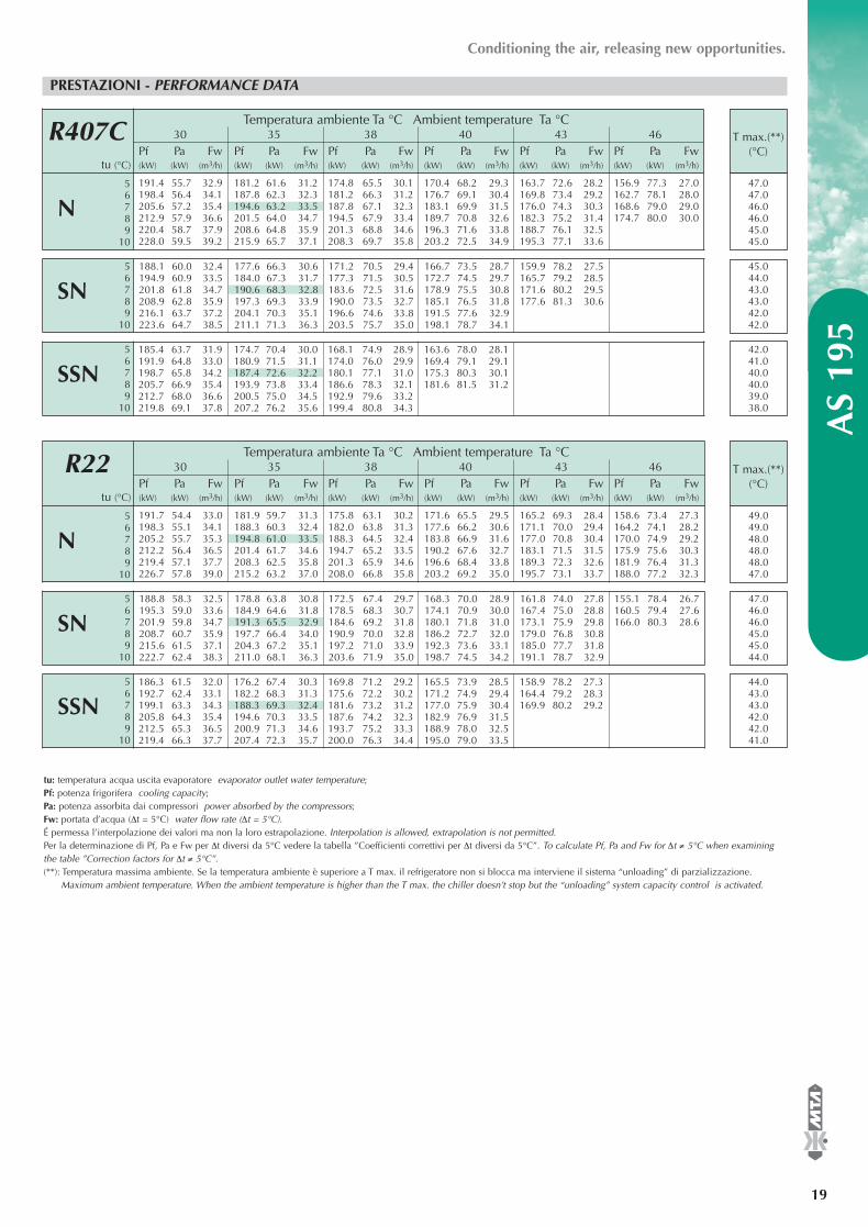
®
AS
195
19
Conditioning the air, releasing new opportunities.
PRESTAZIONI - PERFORMANCE DATA
R407C
56
SSN 789
10
56
SN 789
10
56
N 789
10
Temperatura ambiente Ta °C Ambient temperature Ta °C30 35 38 40 43 46
Pf Pa Fw Pf Pa Fw Pf Pa Fw Pf Pa Fw Pf Pa Fw Pf Pa Fwtu (°C) (kW) (kW) (m3/h) (kW) (kW) (m3/h) (kW) (kW) (m3/h) (kW) (kW) (m3/h) (kW) (kW) (m3/h) (kW) (kW) (m3/h)
191.4 55.7 32.9 181.2 61.6 31.2 174.8 65.5 30.1 170.4 68.2 29.3 163.7 72.6 28.2 156.9 77.3 27.0198.4 56.4 34.1 187.8 62.3 32.3 181.2 66.3 31.2 176.7 69.1 30.4 169.8 73.4 29.2 162.7 78.1 28.0205.6 57.2 35.4 194.6 63.2 33.5 187.8 67.1 32.3 183.1 69.9 31.5 176.0 74.3 30.3 168.6 79.0 29.0212.9 57.9 36.6 201.5 64.0 34.7 194.5 67.9 33.4 189.7 70.8 32.6 182.3 75.2 31.4 174.7 80.0 30.0220.4 58.7 37.9 208.6 64.8 35.9 201.3 68.8 34.6 196.3 71.6 33.8 188.7 76.1 32.5228.0 59.5 39.2 215.9 65.7 37.1 208.3 69.7 35.8 203.2 72.5 34.9 195.3 77.1 33.6
188.1 60.0 32.4 177.6 66.3 30.6 171.2 70.5 29.4 166.7 73.5 28.7 159.9 78.2 27.5194.9 60.9 33.5 184.0 67.3 31.7 177.3 71.5 30.5 172.7 74.5 29.7 165.7 79.2 28.5201.8 61.8 34.7 190.6 68.3 32.8 183.6 72.5 31.6 178.9 75.5 30.8 171.6 80.2 29.5208.9 62.8 35.9 197.3 69.3 33.9 190.0 73.5 32.7 185.1 76.5 31.8 177.6 81.3 30.6216.1 63.7 37.2 204.1 70.3 35.1 196.6 74.6 33.8 191.5 77.6 32.9223.6 64.7 38.5 211.1 71.3 36.3 203.5 75.7 35.0 198.1 78.7 34.1
T max.(**)(°C)
45.044.043.043.042.042.0
42.041.040.040.039.038.0
tu: temperatura acqua uscita evaporatore evaporator outlet water temperature;Pf: potenza frigorifera cooling capacity; Pa: potenza assorbita dai compressori power absorbed by the compressors;Fw: portata d’acqua (∆t = 5°C) water flow rate (∆t = 5°C).É permessa l’interpolazione dei valori ma non la loro estrapolazione. Interpolation is allowed, extrapolation is not permitted.Per la determinazione di Pf, Pa e Fw per ∆t diversi da 5°C vedere la tabella ”Coefficienti correttivi per ∆t diversi da 5°C”. To calculate Pf, Pa and Fw for ∆t ≠ 5°C when examiningthe table ”Correction factors for ∆t ≠ 5°C”.(**): Temperatura massima ambiente. Se la temperatura ambiente è superiore a T max. il refrigeratore non si blocca ma interviene il sistema “unloading” di parzializzazione.
Maximum ambient temperature. When the ambient temperature is higher than the T max. the chiller doesn’t stop but the “unloading” system capacity control is activated.
47.047.046.046.045.045.0
185.4 63.7 31.9 174.7 70.4 30.0 168.1 74.9 28.9 163.6 78.0 28.1191.9 64.8 33.0 180.9 71.5 31.1 174.0 76.0 29.9 169.4 79.1 29.1198.7 65.8 34.2 187.4 72.6 32.2 180.1 77.1 31.0 175.3 80.3 30.1205.7 66.9 35.4 193.9 73.8 33.4 186.6 78.3 32.1 181.6 81.5 31.2212.7 68.0 36.6 200.5 75.0 34.5 192.9 79.6 33.2219.8 69.1 37.8 207.2 76.2 35.6 199.4 80.8 34.3
R22
56
SSN 789
10
56
SN 789
10
56
N 789
10
Temperatura ambiente Ta °C Ambient temperature Ta °C30 35 38 40 43 46
Pf Pa Fw Pf Pa Fw Pf Pa Fw Pf Pa Fw Pf Pa Fw Pf Pa Fwtu (°C) (kW) (kW) (m3/h) (kW) (kW) (m3/h) (kW) (kW) (m3/h) (kW) (kW) (m3/h) (kW) (kW) (m3/h) (kW) (kW) (m3/h)
191.7 54.4 33.0 181.9 59.7 31.3 175.8 63.1 30.2 171.6 65.5 29.5 165.2 69.3 28.4 158.6 73.4 27.3198.3 55.1 34.1 188.3 60.3 32.4 182.0 63.8 31.3 177.6 66.2 30.6 171.1 70.0 29.4 164.2 74.1 28.2205.2 55.7 35.3 194.8 61.0 33.5 188.3 64.5 32.4 183.8 66.9 31.6 177.0 70.8 30.4 170.0 74.9 29.2212.2 56.4 36.5 201.4 61.7 34.6 194.7 65.2 33.5 190.2 67.6 32.7 183.1 71.5 31.5 175.9 75.6 30.3219.4 57.1 37.7 208.3 62.5 35.8 201.3 65.9 34.6 196.6 68.4 33.8 189.3 72.3 32.6 181.9 76.4 31.3226.7 57.8 39.0 215.2 63.2 37.0 208.0 66.8 35.8 203.2 69.2 35.0 195.7 73.1 33.7 188.0 77.2 32.3
188.8 58.3 32.5 178.8 63.8 30.8 172.5 67.4 29.7 168.3 70.0 28.9 161.8 74.0 27.8 155.1 78.4 26.7195.3 59.0 33.6 184.9 64.6 31.8 178.5 68.3 30.7 174.1 70.9 30.0 167.4 75.0 28.8 160.5 79.4 27.6201.9 59.8 34.7 191.3 65.5 32.9 184.6 69.2 31.8 180.1 71.8 31.0 173.1 75.9 29.8 166.0 80.3 28.6208.7 60.7 35.9 197.7 66.4 34.0 190.9 70.0 32.8 186.2 72.7 32.0 179.0 76.8 30.8215.6 61.5 37.1 204.3 67.2 35.1 197.2 71.0 33.9 192.3 73.6 33.1 185.0 77.7 31.8222.7 62.4 38.3 211.0 68.1 36.3 203.6 71.9 35.0 198.7 74.5 34.2 191.1 78.7 32.9
T max.(**)(°C)
47.046.046.045.045.044.0
44.043.043.042.042.041.0
49.049.048.048.048.047.0
186.3 61.5 32.0 176.2 67.4 30.3 169.8 71.2 29.2 165.5 73.9 28.5 158.9 78.2 27.3192.7 62.4 33.1 182.2 68.3 31.3 175.6 72.2 30.2 171.2 74.9 29.4 164.4 79.2 28.3199.1 63.3 34.3 188.3 69.3 32.4 181.6 73.2 31.2 177.0 75.9 30.4 169.9 80.2 29.2205.8 64.3 35.4 194.6 70.3 33.5 187.6 74.2 32.3 182.9 76.9 31.5212.5 65.3 36.5 200.9 71.3 34.6 193.7 75.2 33.3 188.9 78.0 32.5219.4 66.3 37.7 207.4 72.3 35.7 200.0 76.3 34.4 195.0 79.0 33.5
EASYY000BD_V 07-04-2006 12.14 Pagina 19

N
SN
SSN
N SN SSN
Circuiti frigoriferi Cooling circuits N° 2
Compressori Compressors N° 2+2
Gradini di parzializzazione Capacity control % 0 - 25 - 50 - 75 - 100
Alimentazione elettrica Electrical power supply
Potenza Power V / Ph 400±10%/3/50
Ausiliari Auxiliary V / Ph 220±10%/1/50
Batterie condensanti Condenser Coils
Batterie Coils N° 2 2 2
Ranghi Rows N° 3 3 2
Superficie frontale totale Total frontal surface m2 7.26 7.26 10.89
Ventilatori Fans
Ventilatori Fans N° 4 4 6
Portata aria singola batteria Condenser coil airflow (each) m3/h 39843 29188 33281
Potenza (ciascuno) Power (each) kW 2 1.25 0.7
Evaporatore a piastre Evaporator plate type
Portata min/max evaporatore Min/max evaporator flow rate m3/h 14.9 / 39.8
Volume d’acqua evaporatore Evaporator water volume l 12.32
Evaporatore a fascio tubiero Evaporator shell and tube type
Portata min/max evaporatore Min/max evaporator flow rate m3/h 17.9 / 43
Volume d’acqua evaporatore Evaporator water volume l 58.1
Dimensioni e peso Dimensions and weight
Larghezza Width mm 2188 2188 2188
Profondità Length mm 3495 3495 4595
Altezza Height mm 1989 1989 1989
Peso Weight kg 2150 2150 2282
Disegno di ingombro Overall dimensions fig. 1 1 2
PRESTAZIONI E DATI TECNICI - PERFORMANCE AND TECHNICAL DATA A
S 20
9
20
®
DATI GENERALI - GENERAL DATA R407C - R22
ASSORBIMENTI ELETTRICI ELECTRICAL DATA
R407C R22
FLI (kW) FLA (A) ICF (A) FLI (kW) FLA (A) ICF (A)
97 161 337 96 160 336
94 154 330 93 153 330
93 152 328 92 151 327Ver
sion
eV
ersi
on
Dati relativi ad impianti senza pompe. Data refers to unit without pumps.FLI = potenza assorbita a pieno carico power absorbed at full load; FLA = corrente assorbita a pieno carico current absorbed at full load;ICF = corrente di spunto alla partenza dell’ultimo compressore (avviamento diretto)* Start-up current at the start of the last compressor (direct starting)* . I valori massimi sono riferiti alle massime condizioni di funzionamento The maximum values refer to the maximum working conditions.(*): Massima corrente assorbita dalla macchina all’avviamento dell’ultimo compressore, quando gli altri compressori e i ventilatori funzionano alle massime condizioni di lavoro (FLA).
Maximum current absorbed from unit at the start of the last compressor when the other compressors and fans work at the maximum working conditions (FLA).
RUMOROSITA’ - SOUND PRESSURE LEVELS R407C - R22
1 15
3 10
5 6
10 0
DistanzaDistance (2)
L (m)Kdb
(1) Livello di pressione sonora in condizioni di irraggiamento emisferico (campo aperto) ad una distanza di 10 metri dalla macchina lato condensatori ed a 1.2 m dal suolo (valori con tolleranza ± 2 dB). (1) Sound pressure level at hemispherical irradiation conditions (open field) at a distance of 10 meters from the unit (condenser side) and at a height of 1.2 m from the ground (tolerance value ± 2 dB). (2) Per calcolare il livello di pressione sonora ad una distanza diversa impiegare la formula: dB(A)L=dB(A)10m+Kdb. (2) To calculate a different distance of the sound pressure level, use the formula: dB(A)L=dB(A)10m+Kdb.
GRUPPO POMPA E SERBATOIO - PUMP AND TANK SET R407C - R22
14.9 17.7 20.5 23.3 26.1 29.0 31.8 34.6 37.4 40.2 43.0
3.6 3.4 3.3 3.1 3.0 2.8 2.5 2.3 2.0 1.7 1.4
3.9 3.8 3.7 3.6 3.5 3.4 3.3 3.2 3.0 2.9 2.7
4
7.5
400
P2: pompa 2bar; pump 2barP3: pompa 3bar; pump 3bar
Portata acqua Water flow rate m3/h
Prevalenza disponibile P2 Available head pressure P2 bar
Prevalenza disponibile P3 Available head pressure P2 bar
Potenza nominale P2 Nominal power P2 kW
Potenza nominale P3 Nominal power P3 kW
Volume serbatoio Tank volume l
N
SN
SSN
Bande d’ottava Octave bands (Hz)
63 125 250 500 1000 2000 4000 8000
dB10m(1)
55.4 62.9 66.9 62.4 59.2 55.1 47.4 39.1 64.6
48.8 56.3 60.3 55.8 52.6 48.5 40.8 32.5 58.0
51.4 50.9 51.9 46.8 45.1 39.5 31.4 21.3 49.7Ver
sion
eV
ersi
on
dB(A)10m(1)
EASYY000BD_V 07-04-2006 12.14 Pagina 20

®
AS
209
21
Conditioning the air, releasing new opportunities.
PRESTAZIONI - PERFORMANCE DATA
R407C
56
SSN 789
10
56
SN 789
10
56
N 789
10
Temperatura ambiente Ta °C Ambient temperature Ta °C30 35 38 40 43 46
Pf Pa Fw Pf Pa Fw Pf Pa Fw Pf Pa Fw Pf Pa Fw Pf Pa Fwtu (°C) (kW) (kW) (m3/h) (kW) (kW) (m3/h) (kW) (kW) (m3/h) (kW) (kW) (m3/h) (kW) (kW) (m3/h) (kW) (kW) (m3/h)
204.6 58.3 35.2 194.0 64.4 33.4 187.4 68.4 32.2 182.9 71.3 31.5 176.0 75.9 30.3 168.9 80.8 29.1212.2 59.0 36.5 201.2 65.2 34.6 194.3 69.2 33.4 189.7 72.1 32.6 182.5 76.8 31.4 175.2 81.8 30.1219.9 59.7 37.8 208.5 66.0 35.9 201.4 70.1 34.6 196.6 73.0 33.8 189.3 77.7 32.6 181.7 82.7 31.3227.8 60.6 39.2 216.0 66.8 37.2 208.7 71.0 35.9 203.7 73.9 35.0 196.1 78.6 33.7235.9 61.4 40.6 223.7 67.7 38.5 216.1 71.9 37.2 211.0 74.9 36.3 203.1 79.6 34.9244.2 62.2 42.0 231.6 68.6 39.8 223.7 72.9 38.5 218.5 75.9 37.6 210.3 80.6 36.2
201.1 62.8 34.6 190.3 69.5 32.7 183.6 73.8 31.6 179.0 76.9 30.8 172.0 81.9 29.6208.5 63.8 35.9 197.2 70.4 33.9 190.3 74.9 32.7 185.5 78.0 31.9 178.3 83.0 30.7215.9 64.8 37.1 204.3 71.5 35.1 197.1 76.0 33.9 192.2 79.1 33.1 184.7 84.2 31.8223.6 65.7 38.5 211.6 72.6 36.4 204.1 77.1 35.1 199.0 80.3 34.2231.4 66.8 39.8 219.0 73.7 37.7 211.3 78.2 36.3 206.0 81.5 35.4239.4 67.8 41.2 226.5 74.8 39.0 218.5 79.4 37.6 213.1 82.7 36.7
T max.(**)(°C)
44.043.043.042.041.041.0
42.041.041.040.039.039.0
tu: temperatura acqua uscita evaporatore evaporator outlet water temperature;Pf: potenza frigorifera cooling capacity; Pa: potenza assorbita dai compressori power absorbed by the compressors;Fw: portata d’acqua (∆t = 5°C) water flow rate (∆t = 5°C).É permessa l’interpolazione dei valori ma non la loro estrapolazione. Interpolation is allowed, extrapolation is not permitted.Per la determinazione di Pf, Pa e Fw per ∆t diversi da 5°C vedere la tabella ”Coefficienti correttivi per ∆t diversi da 5°C”. To calculate Pf, Pa and Fw for ∆t ≠ 5°C when examiningthe table ”Correction factors for ∆t ≠ 5°C”.(**): Temperatura massima ambiente. Se la temperatura ambiente è superiore a T max. il refrigeratore non si blocca ma interviene il sistema “unloading” di parzializzazione.
Maximum ambient temperature. When the ambient temperature is higher than the T max. the chiller doesn’t stop but the “unloading” system capacity control is activated.
47.046.046.045.045.044.0
201.0 63.1 34.6 190.1 69.7 32.7 183.4 74.1 31.5 178.8 77.2 30.8208.3 64.0 35.8 197.1 70.7 33.9 190.1 75.2 32.7 185.4 78.3 31.9215.7 65.0 37.1 204.1 71.8 35.1 196.9 76.3 33.9 192.0 79.5 33.0223.4 66.0 38.4 211.4 72.9 36.4 203.9 77.4 35.1 198.8 80.6 34.2231.2 67.0 39.8 218.7 74.0 37.6 211.0 78.6 36.3239.1 68.1 41.1 226.3 75.1 38.9 218.3 79.8 37.5
R22
56
SSN 789
10
56
SN 789
10
56
N 789
10
Temperatura ambiente Ta °C Ambient temperature Ta °C30 35 38 40 43 46
Pf Pa Fw Pf Pa Fw Pf Pa Fw Pf Pa Fw Pf Pa Fw Pf Pa Fwtu (°C) (kW) (kW) (m3/h) (kW) (kW) (m3/h) (kW) (kW) (m3/h) (kW) (kW) (m3/h) (kW) (kW) (m3/h) (kW) (kW) (m3/h)
205.1 57.5 35.3 195.3 63.0 33.6 189.1 66.6 32.5 184.9 69.1 31.8 178.5 73.2 30.7 171.8 77.6 29.6212.3 58.1 36.5 202.1 63.7 34.8 195.7 67.3 33.7 191.4 69.9 32.9 184.7 74.0 31.8 177.9 78.4 30.6219.6 58.8 37.8 209.0 64.4 36.0 202.5 68.0 34.8 198.0 70.6 34.1 191.1 74.7 32.9 184.1 79.1 31.7227.0 59.5 39.0 216.2 65.1 37.2 209.4 68.8 36.0 204.8 71.4 35.2 197.7 75.5 34.0 190.4 80.0 32.8234.6 60.2 40.4 223.4 65.9 38.4 216.4 69.6 37.2 211.7 72.2 36.4 204.4 76.3 35.2 196.9 80.8 33.9242.4 61.0 41.7 230.9 66.7 39.7 223.6 70.4 38.5 218.7 73.0 37.6 211.2 77.2 36.3 203.5 81.7 35.0
202.4 61.5 34.8 192.3 67.4 33.1 186.1 71.3 32.0 181.8 74.1 31.3 175.2 78.5 30.1 168.5 83.2 29.0209.4 62.4 36.0 199.0 68.3 34.2 192.5 72.2 33.1 188.1 75.0 32.3 181.3 79.4 31.2 174.3 84.2 30.0216.4 63.2 37.2 205.7 69.2 35.4 199.0 73.1 34.2 194.5 75.9 33.4 187.5 80.4 32.2223.7 64.1 38.5 212.6 70.1 36.6 205.7 74.1 35.4 201.0 76.9 34.6 193.8 81.3 33.3231.1 64.9 39.8 219.7 71.0 37.8 212.6 75.0 36.6 207.7 77.8 35.7 200.3 82.3 34.4238.7 65.9 41.1 226.9 72.0 39.0 219.5 76.0 37.8 214.5 78.9 36.9 206.9 83.4 35.6
T max.(**)(°C)
46.046.045.044.044.043.0
44.043.043.042.042.041.0
49.048.048.048.047.047.0
202.3 61.7 34.8 192.2 67.7 33.1 185.9 71.6 32.0 181.6 74.3 31.2 175.1 78.8 30.1209.2 62.6 36.0 198.8 68.5 34.2 192.3 72.5 33.1 187.9 75.2 32.3 181.1 79.7 31.2216.3 63.4 37.2 205.6 69.4 35.4 198.8 73.4 34.2 194.3 76.2 33.4 187.3 80.6 32.2223.6 64.3 38.5 212.5 70.3 36.5 205.5 74.3 35.4 200.8 77.1 34.5230.9 65.2 39.7 219.5 71.3 37.8 212.4 75.3 36.5 207.5 78.1 35.7238.5 66.1 41.0 226.7 72.3 39.0 219.3 76.3 37.7 214.3 79.2 36.9
EASYY000BD_V 07-04-2006 12.14 Pagina 21

N
SN
SSN
N SN SSN
Circuiti frigoriferi Cooling circuits N° 2
Compressori Compressors N° 2+2
Gradini di parzializzazione Capacity control % 0 - 25 - 50 - 75 - 100
Alimentazione elettrica Electrical power supply
Potenza Power V / Ph 400±10%/3/50
Ausiliari Auxiliary V / Ph 220±10%/1/50
Batterie condensanti Condenser Coils
Batterie Coils N° 2 2 2
Ranghi Rows N° 3 3 2
Superficie frontale totale Total frontal surface m2 7.26 7.26 10.89
Ventilatori Fans
Ventilatori Fans N° 4 4 6
Portata aria singola batteria Condenser coil airflow (each) m3/h 39843 29188 33281
Potenza (ciascuno) Power (each) kW 2 1.25 0.7
Evaporatore a piastre Evaporator plate type
Portata min/max evaporatore Min/max evaporator flow rate m3/h 15.7 / 43.6
Volume d’acqua evaporatore Evaporator water volume l 14.24
Evaporatore a fascio tubiero Evaporator shell and tube type
Portata min/max evaporatore Min/max evaporator flow rate m3/h 18.8 / 43
Volume d’acqua evaporatore Evaporator water volume l 58.1
Dimensioni e peso Dimensions and weight
Larghezza Width mm 2188 2188 2188
Profondità Length mm 3495 3495 4595
Altezza Height mm 1989 1989 1989
Peso Weight kg 2207 2207 2339
Disegno di ingombro Overall dimensions fig. 1 1 2
PRESTAZIONI E DATI TECNICI - PERFORMANCE AND TECHNICAL DATA A
S 21
9
22
®
DATI GENERALI - GENERAL DATA R407C - R22
ASSORBIMENTI ELETTRICI ELECTRICAL DATA
R407C R22
FLI (kW) FLA (A) ICF (A) FLI (kW) FLA (A) ICF (A)
103 170 347 102 170 347
100 163 340 99 163 340
100 161 337 98 161 337Ver
sion
eV
ersi
on
Dati relativi ad impianti senza pompe. Data refers to unit without pumps.FLI = potenza assorbita a pieno carico power absorbed at full load; FLA = corrente assorbita a pieno carico current absorbed at full load;ICF = corrente di spunto alla partenza dell’ultimo compressore (avviamento diretto)* Start-up current at the start of the last compressor (direct starting)* . I valori massimi sono riferiti alle massime condizioni di funzionamento The maximum values refer to the maximum working conditions.(*): Massima corrente assorbita dalla macchina all’avviamento dell’ultimo compressore, quando gli altri compressori e i ventilatori funzionano alle massime condizioni di lavoro (FLA).
Maximum current absorbed from unit at the start of the last compressor when the other compressors and fans work at the maximum working conditions (FLA).
RUMOROSITA’ - SOUND PRESSURE LEVELS R407C - R22
1 15
3 10
5 6
10 0
DistanzaDistance (2)
L (m)Kdb
(1) Livello di pressione sonora in condizioni di irraggiamento emisferico (campo aperto) ad una distanza di 10 metri dalla macchina lato condensatori ed a 1.2 m dal suolo (valori con tolleranza ± 2 dB). (1) Sound pressure level at hemispherical irradiation conditions (open field) at a distance of 10 meters from the unit (condenser side) and at a height of 1.2 m from the ground (tolerance value ± 2 dB). (2) Per calcolare il livello di pressione sonora ad una distanza diversa impiegare la formula: dB(A)L=dB(A)10m+Kdb. (2) To calculate a different distance of the sound pressure level, use the formula: dB(A)L=dB(A)10m+Kdb.
GRUPPO POMPA E SERBATOIO - PUMP AND TANK SET R407C - R22
15.7 18.4 21.2 23.9 26.6 29.4 32.1 34.8 37.5 40.3 43.0
3.5 3.4 3.3 3.1 2.9 2.7 2.5 2.3 2.0 1.7 1.4
3.8 3.8 3.7 3.6 3.5 3.4 3.3 3.2 3.1 2.9 2.8
4
7.5
400
P2: pompa 2bar; pump 2barP3: pompa 3bar; pump 3bar
Portata acqua Water flow rate m3/h
Prevalenza disponibile P2 Available head pressure P2 bar
Prevalenza disponibile P3 Available head pressure P2 bar
Potenza nominale P2 Nominal power P2 kW
Potenza nominale P3 Nominal power P3 kW
Volume serbatoio Tank volume l
N
SN
SSN
Bande d’ottava Octave bands (Hz)
63 125 250 500 1000 2000 4000 8000
dB10m(1)
55.4 62.9 66.9 62.4 59.2 55.1 47.4 39.1 64.6
48.8 56.3 60.3 55.8 52.6 48.5 40.8 32.5 58.0
51.4 50.9 51.9 46.8 45.1 39.5 31.4 21.3 49.7Ver
sion
eV
ersi
on
dB(A)10m(1)
EASYY000BD_V 07-04-2006 12.14 Pagina 22

®
AS
219
23
Conditioning the air, releasing new opportunities.
PRESTAZIONI - PERFORMANCE DATA
R407C
56
SSN 789
10
56
SN 789
10
56
N 789
10
Temperatura ambiente Ta °C Ambient temperature Ta °C30 35 38 40 43 46
Pf Pa Fw Pf Pa Fw Pf Pa Fw Pf Pa Fw Pf Pa Fw Pf Pa Fwtu (°C) (kW) (kW) (m3/h) (kW) (kW) (m3/h) (kW) (kW) (m3/h) (kW) (kW) (m3/h) (kW) (kW) (m3/h) (kW) (kW) (m3/h)
214.7 62.7 36.9 203.6 69.2 35.0 196.8 73.6 33.9 192.2 76.7 33.1 185.1 81.6 31.8 177.9 87.0 30.6222.6 63.5 38.3 211.2 70.1 36.3 204.2 74.5 35.1 199.4 77.7 34.3 192.0 82.7 33.0 184.5 88.1 31.7230.7 64.4 39.7 218.9 71.1 37.7 211.7 75.5 36.4 206.7 78.7 35.5 199.1 83.7 34.2 191.3 89.2 32.9239.0 65.4 41.1 226.9 72.1 39.0 219.3 76.5 37.7 214.1 79.7 36.8 206.3 84.8 35.5247.6 66.3 42.6 235.0 73.1 40.4 227.2 77.7 39.1 221.8 80.8 38.2 213.7 86.0 36.8256.3 67.3 44.1 243.3 74.2 41.8 235.2 78.8 40.5 229.7 82.0 39.5 221.3 87.1 38.1
210.9 67.9 36.3 199.6 75.0 34.3 192.7 79.7 33.1 188.0 83.1 32.3 180.8 88.6 31.1218.6 68.9 37.6 206.9 76.2 35.6 199.8 81.0 34.4 194.9 84.4 33.5 187.5 89.9 32.2226.5 70.1 39.0 214.4 77.4 36.9 207.0 82.3 35.6 201.9 85.7 34.7 194.2 91.3 33.4234.4 71.2 40.3 222.0 78.6 38.2 214.3 83.5 36.9 209.1 87.1 36.0242.6 72.4 41.7 229.8 79.9 39.5 221.8 84.9 38.2 216.5 88.4 37.2251.0 73.6 43.2 237.7 81.2 40.9 229.5 86.3 39.5 223.9 89.9 38.5
T max.(**)(°C)
44.043.043.042.041.041.0
42.041.041.040.039.039.0
tu: temperatura acqua uscita evaporatore evaporator outlet water temperature;Pf: potenza frigorifera cooling capacity; Pa: potenza assorbita dai compressori power absorbed by the compressors;Fw: portata d’acqua (∆t = 5°C) water flow rate (∆t = 5°C).É permessa l’interpolazione dei valori ma non la loro estrapolazione. Interpolation is allowed, extrapolation is not permitted.Per la determinazione di Pf, Pa e Fw per ∆t diversi da 5°C vedere la tabella ”Coefficienti correttivi per ∆t diversi da 5°C”. To calculate Pf, Pa and Fw for ∆t ≠ 5°C when examiningthe table ”Correction factors for ∆t ≠ 5°C”.(**): Temperatura massima ambiente. Se la temperatura ambiente è superiore a T max. il refrigeratore non si blocca ma interviene il sistema “unloading” di parzializzazione.
Maximum ambient temperature. When the ambient temperature is higher than the T max. the chiller doesn’t stop but the “unloading” system capacity control is activated.
47.046.046.045.045.044.0
210.7 68.1 36.2 199.5 75.3 34.3 192.5 80.0 33.1 187.8 83.4 32.3218.4 69.2 37.6 206.8 76.5 35.6 199.5 81.3 34.3 194.7 84.8 33.5226.2 70.3 38.9 214.2 77.7 36.8 206.7 82.6 35.6 201.7 86.1 34.7234.3 71.5 40.3 221.7 78.9 38.1 214.1 83.9 36.8 208.9 87.4 35.9242.4 72.7 41.7 229.6 80.2 39.5 221.6 85.3 38.1250.8 74.0 43.1 237.5 81.6 40.8 229.2 86.7 39.4
R22
56
SSN 789
10
56
SN 789
10
56
N 789
10
Temperatura ambiente Ta °C Ambient temperature Ta °C30 35 38 40 43 46
Pf Pa Fw Pf Pa Fw Pf Pa Fw Pf Pa Fw Pf Pa Fw Pf Pa Fwtu (°C) (kW) (kW) (m3/h) (kW) (kW) (m3/h) (kW) (kW) (m3/h) (kW) (kW) (m3/h) (kW) (kW) (m3/h) (kW) (kW) (m3/h)
213.4 62.2 36.7 203.4 68.1 35.0 197.2 72.0 33.9 193.0 74.8 33.2 186.5 79.2 32.1 179.9 84.0 30.9220.7 62.9 38.0 210.4 68.9 36.2 204.0 72.8 35.1 199.7 75.6 34.3 193.0 80.1 33.2 186.2 84.9 32.0228.2 63.7 39.2 217.6 69.7 37.4 211.0 73.7 36.3 206.5 76.5 35.5 199.6 81.0 34.3 192.5 85.8 33.1235.9 64.5 40.6 224.9 70.6 38.7 218.1 74.5 37.5 213.4 77.4 36.7 206.3 81.9 35.5 199.1 86.8 34.2243.6 65.3 41.9 232.3 71.4 40.0 225.3 75.4 38.8 220.6 78.3 37.9 213.2 82.8 36.7 205.7 87.7 35.4251.6 66.2 43.3 240.0 72.3 41.3 232.7 76.3 40.0 227.8 79.2 39.2 220.3 83.8 37.9 212.6 88.7 36.6
210.5 66.8 36.2 200.3 73.2 34.5 194.0 77.5 33.4 189.7 80.5 32.6 183.1 85.4 31.5 176.4 90.7 30.3217.6 67.7 37.4 207.1 74.2 35.6 200.6 78.5 34.5 196.1 81.6 33.7 189.4 86.5 32.6 182.4 91.8 31.4224.9 68.7 38.7 214.1 75.2 36.8 207.3 79.5 35.7 202.8 82.6 34.9 195.8 87.6 33.7232.4 69.6 40.0 221.2 76.2 38.0 214.2 80.6 36.8 209.5 83.7 36.0 202.3 88.7 34.8239.9 70.7 41.3 228.4 77.3 39.3 221.2 81.7 38.1 216.4 84.8 37.2 208.9 89.8 35.9247.7 71.8 42.6 235.8 78.4 40.6 228.4 82.8 39.3 223.4 86.0 38.4 215.7 91.0 37.1
T max.(**)(°C)
46.046.045.044.044.043.0
44.043.043.042.042.041.0
49.048.048.048.047.047.0
210.4 67.0 36.2 200.2 73.5 34.4 193.9 77.8 33.3 189.6 80.8 32.6 183.0 85.7 31.5217.5 68.0 37.4 207.0 74.5 35.6 200.4 78.8 34.5 196.0 81.9 33.7 189.2 86.8 32.5224.7 68.9 38.7 213.9 75.5 36.8 207.2 79.8 35.6 202.6 82.9 34.8 195.6 87.9 33.6232.2 69.9 39.9 221.0 76.5 38.0 214.0 80.9 36.8 209.3 84.0 36.0239.8 70.9 41.2 228.2 77.6 39.2 221.0 82.0 38.0 216.2 85.2 37.2247.5 72.0 42.6 235.6 78.7 40.5 228.2 83.1 39.2 223.2 86.3 38.4
EASYY000BD_V 07-04-2006 12.14 Pagina 23

N
SN
SSN
N SN SSN
Circuiti frigoriferi Cooling circuits N° 2
Compressori Compressors N° 2+2
Gradini di parzializzazione Capacity control % 0 - 25 - 50 - 75 - 100
Alimentazione elettrica Electrical power supply
Potenza Power V / Ph 400±10%/3/50
Ausiliari Auxiliary V / Ph 220±10%/1/50
Batterie condensanti Condenser Coils
Batterie Coils N° 2 2 2
Ranghi Rows N° 3 3 3
Superficie frontale totale Total frontal surface m2 10.89 10.89 10.89
Ventilatori Fans
Ventilatori Fans N° 4 4 6
Portata aria singola batteria Condenser coil airflow (each) m3/h 44438 33781 31172
Potenza (ciascuno) Power (each) kW 2 1.25 0.7
Evaporatore a piastre Evaporator plate type
Portata min/max evaporatore Min/max evaporator flow rate m3/h 17.7 / 52.9
Volume d’acqua evaporatore Evaporator water volume l 22.05
Evaporatore a fascio tubiero Evaporator shell and tube type
Portata min/max evaporatore Min/max evaporator flow rate m3/h 21.2 / 65
Volume d’acqua evaporatore Evaporator water volume l 93.3
Dimensioni e peso Dimensions and weight
Larghezza Width mm 2188 2188 2188
Profondità Length mm 4595 4595 4595
Altezza Height mm 1989 1989 1989
Peso Weight kg 2458 2458 2460
Disegno di ingombro Overall dimensions fig. 2 2 2
PRESTAZIONI E DATI TECNICI - PERFORMANCE AND TECHNICAL DATA A
S 24
7
24
®
DATI GENERALI - GENERAL DATA R407C - R22
ASSORBIMENTI ELETTRICI ELECTRICAL DATA
R407C R22
FLI (kW) FLA (A) ICF (A) FLI (kW) FLA (A) ICF (A)
114 187 410 114 177 399
111 181 403 111 170 392
110 178 401 110 168 390Ver
sion
eV
ersi
on
Dati relativi ad impianti senza pompe. Data refers to unit without pumps.FLI = potenza assorbita a pieno carico power absorbed at full load; FLA = corrente assorbita a pieno carico current absorbed at full load;ICF = corrente di spunto alla partenza dell’ultimo compressore (avviamento diretto)* Start-up current at the start of the last compressor (direct starting)* . I valori massimi sono riferiti alle massime condizioni di funzionamento The maximum values refer to the maximum working conditions.(*): Massima corrente assorbita dalla macchina all’avviamento dell’ultimo compressore, quando gli altri compressori e i ventilatori funzionano alle massime condizioni di lavoro (FLA).
Maximum current absorbed from unit at the start of the last compressor when the other compressors and fans work at the maximum working conditions (FLA).
RUMOROSITA’ - SOUND PRESSURE LEVELS R407C - R22
1 15
3 10
5 6
10 0
DistanzaDistance (2)
L (m)Kdb
(1) Livello di pressione sonora in condizioni di irraggiamento emisferico (campo aperto) ad una distanza di 10 metri dalla macchina lato condensatori ed a 1.2 m dal suolo (valori con tolleranza ± 2 dB). (1) Sound pressure level at hemispherical irradiation conditions (open field) at a distance of 10 meters from the unit (condenser side) and at a height of 1.2 m from the ground (tolerance value ± 2 dB). (2) Per calcolare il livello di pressione sonora ad una distanza diversa impiegare la formula: dB(A)L=dB(A)10m+Kdb. (2) To calculate a different distance of the sound pressure level, use the formula: dB(A)L=dB(A)10m+Kdb.
GRUPPO POMPA E SERBATOIO - PUMP AND TANK SET R407C - R22
17.7 22.4 27.2 31.9 36.6 41.4 46.1 50.8 55.5 60.3 65.0
3.1 3.0 2.9 2.8 2.6 2.4 2.1 1.9 1.6 1.2 0.9
4.9 4.8 4.7 4.5 4.3 4.0 3.7 3.3 3.0 2.5 2.1
5.5
9.2
400
P2: pompa 2bar; pump 2barP3: pompa 3bar; pump 3bar
Portata acqua Water flow rate m3/h
Prevalenza disponibile P2 Available head pressure P2 bar
Prevalenza disponibile P3 Available head pressure P2 bar
Potenza nominale P2 Nominal power P2 kW
Potenza nominale P3 Nominal power P3 kW
Volume serbatoio Tank volume l
N
SN
SSN
Bande d’ottava Octave bands (Hz)
63 125 250 500 1000 2000 4000 8000
dB10m(1)
55.4 62.9 66.9 62.4 59.2 55.1 47.4 39.1 64.6
48.8 56.3 60.3 55.8 52.6 48.5 40.8 32.5 58.0
52.4 51.9 52.9 47.8 46.1 40.5 32.4 22.3 50.7Ver
sion
eV
ersi
on
dB(A)10m(1)
EASYY000BD_V 07-04-2006 12.14 Pagina 24

®
AS
247
25
Conditioning the air, releasing new opportunities.
PRESTAZIONI - PERFORMANCE DATA
R407C
56
SSN 789
10
56
SN 789
10
56
N 789
10
Temperatura ambiente Ta °C Ambient temperature Ta °C30 35 38 40 43 46
Pf Pa Fw Pf Pa Fw Pf Pa Fw Pf Pa Fw Pf Pa Fw Pf Pa Fwtu (°C) (kW) (kW) (m3/h) (kW) (kW) (m3/h) (kW) (kW) (m3/h) (kW) (kW) (m3/h) (kW) (kW) (m3/h) (kW) (kW) (m3/h)
241.5 69.2 41.5 230.0 76.5 39.6 222.7 81.2 38.3 217.7 84.6 37.4 210.0 89.9 36.1 202.0 95.6 34.7250.4 70.1 43.1 238.5 77.5 41.0 230.9 82.3 39.7 225.7 85.7 38.8 217.7 91.1 37.4 209.4 96.8 36.0259.4 71.1 44.6 247.1 78.5 42.5 239.2 83.4 41.2 233.8 86.8 40.2 225.6 92.2 38.8 217.0 98.0 37.3268.7 72.1 46.2 255.9 79.6 44.0 247.8 84.5 42.6 242.3 88.0 41.7 233.7 93.4 40.2 224.8 99.3 38.7278.2 73.2 47.9 265.0 80.8 45.6 256.5 85.7 44.1 250.8 89.2 43.1 241.9 94.7 41.6287.9 74.3 49.5 274.2 82.0 47.2 265.5 86.9 45.7 259.6 90.4 44.6 250.4 95.9 43.1
238.5 74.0 41.0 226.7 81.7 39.0 219.1 86.8 37.7 214.0 90.4 36.8 206.1 96.0 35.5247.1 75.1 42.5 234.8 83.0 40.4 227.1 88.1 39.1 221.8 91.7 38.2 213.6 97.4 36.7255.9 76.4 44.0 243.2 84.2 41.8 235.2 89.5 40.5 229.7 93.1 39.5 221.2 98.8 38.0264.9 77.6 45.6 251.8 85.6 43.3 243.5 90.8 41.9 237.8 94.5 40.9274.2 78.9 47.2 260.6 87.0 44.8 252.0 92.2 43.3 246.0 96.0 42.3283.7 80.2 48.8 269.6 88.4 46.4 260.6 93.7 44.8 254.5 97.4 43.8
T max.(**)(°C)
44.043.043.042.041.041.0
43.043.042.042.041.040.0
tu: temperatura acqua uscita evaporatore evaporator outlet water temperature;Pf: potenza frigorifera cooling capacity; Pa: potenza assorbita dai compressori power absorbed by the compressors;Fw: portata d’acqua (∆t = 5°C) water flow rate (∆t = 5°C).É permessa l’interpolazione dei valori ma non la loro estrapolazione. Interpolation is allowed, extrapolation is not permitted.Per la determinazione di Pf, Pa e Fw per ∆t diversi da 5°C vedere la tabella ”Coefficienti correttivi per ∆t diversi da 5°C”. To calculate Pf, Pa and Fw for ∆t ≠ 5°C when examiningthe table ”Correction factors for ∆t ≠ 5°C”.(**): Temperatura massima ambiente. Se la temperatura ambiente è superiore a T max. il refrigeratore non si blocca ma interviene il sistema “unloading” di parzializzazione.
Maximum ambient temperature. When the ambient temperature is higher than the T max. the chiller doesn’t stop but the “unloading” system capacity control is activated.
47.047.046.046.045.045.0
238.9 73.3 41.1 227.1 81.0 39.1 219.7 86.0 37.8 214.6 89.6 36.9 206.7 95.2 35.5247.6 74.4 42.6 235.3 82.2 40.5 227.6 87.3 39.1 222.3 90.8 38.2 214.1 96.5 36.8256.4 75.6 44.1 243.7 83.5 41.9 235.8 88.6 40.6 230.3 92.2 39.6265.5 76.8 45.7 252.3 84.8 43.4 244.1 90.0 42.0 238.4 93.6 41.0274.7 78.1 47.3 261.1 86.1 44.9 252.6 91.4 43.5 246.7 95.0 42.4284.2 79.4 48.9 270.2 87.5 46.5 261.3 92.8 44.9 255.2 96.5 43.9
R22
56
SSN 789
10
56
SN 789
10
56
N 789
10
Temperatura ambiente Ta °C Ambient temperature Ta °C30 35 38 40 43 46
Pf Pa Fw Pf Pa Fw Pf Pa Fw Pf Pa Fw Pf Pa Fw Pf Pa Fwtu (°C) (kW) (kW) (m3/h) (kW) (kW) (m3/h) (kW) (kW) (m3/h) (kW) (kW) (m3/h) (kW) (kW) (m3/h) (kW) (kW) (m3/h)
243.7 69.7 41.9 232.0 76.2 39.9 224.8 80.5 38.7 219.9 83.6 37.8 212.4 88.4 36.5 204.7 93.7 35.2252.2 70.6 43.4 240.2 77.2 41.3 232.7 81.5 40.0 227.6 84.6 39.1 219.8 89.4 37.8 211.9 94.7 36.4260.8 71.5 44.9 248.4 78.1 42.7 240.7 82.5 41.4 235.5 85.6 40.5 227.4 90.5 39.1 219.2 95.8 37.7269.6 72.5 46.4 256.9 79.1 44.2 248.9 83.5 42.8 243.5 86.6 41.9 235.2 91.6 40.5 226.8 96.9 39.0278.7 73.5 47.9 265.5 80.2 45.7 257.3 84.6 44.3 251.7 87.7 43.3 243.2 92.7 41.8 234.5 98.0 40.3287.9 74.5 49.5 274.3 81.2 47.2 265.9 85.7 45.7 260.1 88.8 44.7 251.3 93.8 43.2 242.3 99.2 41.7
240.8 74.0 41.4 228.9 81.0 39.4 221.6 85.6 38.1 216.6 88.9 37.3 209.0 94.1 35.9 201.2 99.8 34.6249.0 75.1 42.8 236.8 82.1 40.7 229.3 86.7 39.4 224.1 90.0 38.5 216.2 95.3 37.2257.5 76.2 44.3 244.9 83.2 42.1 237.1 87.9 40.8 231.7 91.2 39.9 223.6 96.5 38.5266.1 77.3 45.8 253.1 84.4 43.5 245.0 89.1 42.1 239.5 92.5 41.2 231.1 97.8 39.8275.0 78.5 47.3 261.5 85.6 45.0 253.2 90.4 43.5 247.5 93.8 42.6 238.9 99.1 41.1284.0 79.7 48.8 270.1 87.0 46.5 261.5 91.7 45.0 255.6 95.1 44.0 246.7 100.5 42.4
T max.(**)(°C)
46.045.045.044.044.043.0
45.045.044.044.043.043.0
49.049.048.048.047.047.0
241.2 73.4 41.5 229.3 80.3 39.4 222.0 84.9 38.2 217.1 88.1 37.3 209.4 93.3 36.0249.4 74.5 42.9 237.3 81.4 40.8 229.7 86.0 39.5 224.5 89.3 38.6 216.7 94.5 37.3258.0 75.5 44.4 245.3 82.5 42.2 237.5 87.2 40.9 232.2 90.5 39.9 224.1 95.7 38.5266.6 76.6 45.8 253.6 83.7 43.6 245.5 88.4 42.2 240.0 91.7 41.3 231.7 96.9 39.9275.5 77.8 47.4 262.0 84.9 45.1 253.7 89.6 43.6 248.0 92.9 42.7 239.4 98.2 41.2284.5 79.0 48.9 270.7 86.1 46.6 262.1 90.8 45.1 256.3 94.2 44.1 247.4 99.5 42.5
EASYY000BD_V 07-04-2006 12.14 Pagina 25

N
SN
SSN
N SN SSN
Circuiti frigoriferi Cooling circuits N° 2
Compressori Compressors N° 2+2
Gradini di parzializzazione Capacity control % 0 - 25 - 50 - 75 - 100
Alimentazione elettrica Electrical power supply
Potenza Power V / Ph 400±10%/3/50
Ausiliari Auxiliary V / Ph 220±10%/1/50
Batterie condensanti Condenser Coils
Batterie Coils N° 2 2 2
Ranghi Rows N° 3 3 3
Superficie frontale totale Total frontal surface m2 10.89 10.89 10.89
Ventilatori Fans
Ventilatori Fans N° 4 4 6
Portata aria singola batteria Condenser coil airflow (each) m3/h 44438 33781 31172
Potenza (ciascuno) Power (each) kW 2 1.25 0.7
Evaporatore a piastre Evaporator plate type
Portata min/max evaporatore Min/max evaporator flow rate m3/h 19.1 / 57.2
Volume d’acqua evaporatore Evaporator water volume l 23.85
Evaporatore a fascio tubiero Evaporator shell and tube type
Portata min/max evaporatore Min/max evaporator flow rate m3/h 22.9 / 65
Volume d’acqua evaporatore Evaporator water volume l 93.3
Dimensioni e peso Dimensions and weight
Larghezza Width mm 2188 2188 2188
Profondità Length mm 4595 4595 4595
Altezza Height mm 1989 1989 1989
Peso Weight kg 2458 2458 2460
Disegno di ingombro Overall dimensions fig. 2 2 2
PRESTAZIONI E DATI TECNICI - PERFORMANCE AND TECHNICAL DATA A
S 26
7
26
®
DATI GENERALI - GENERAL DATA R407C - R22
ASSORBIMENTI ELETTRICI ELECTRICAL DATA
R407C R22
FLI (kW) FLA (A) ICF (A) FLI (kW) FLA (A) ICF (A)
124 205 428 126 210 431
121 198 421 123 203 425
120 196 419 123 201 422Ver
sion
eV
ersi
on
Dati relativi ad impianti senza pompe. Data refers to unit without pumps.FLI = potenza assorbita a pieno carico power absorbed at full load; FLA = corrente assorbita a pieno carico current absorbed at full load;ICF = corrente di spunto alla partenza dell’ultimo compressore (avviamento diretto)* Start-up current at the start of the last compressor (direct starting)* . I valori massimi sono riferiti alle massime condizioni di funzionamento The maximum values refer to the maximum working conditions.(*): Massima corrente assorbita dalla macchina all’avviamento dell’ultimo compressore, quando gli altri compressori e i ventilatori funzionano alle massime condizioni di lavoro (FLA).
Maximum current absorbed from unit at the start of the last compressor when the other compressors and fans work at the maximum working conditions (FLA).
RUMOROSITA’ - SOUND PRESSURE LEVELS R407C - R22
1 15
3 10
5 6
10 0
DistanzaDistance (2)
L (m)Kdb
(1) Livello di pressione sonora in condizioni di irraggiamento emisferico (campo aperto) ad una distanza di 10 metri dalla macchina lato condensatori ed a 1.2 m dal suolo (valori con tolleranza ± 2 dB). (1) Sound pressure level at hemispherical irradiation conditions (open field) at a distance of 10 meters from the unit (condenser side) and at a height of 1.2 m from the ground (tolerance value ± 2 dB). (2) Per calcolare il livello di pressione sonora ad una distanza diversa impiegare la formula: dB(A)L=dB(A)10m+Kdb. (2) To calculate a different distance of the sound pressure level, use the formula: dB(A)L=dB(A)10m+Kdb.
GRUPPO POMPA E SERBATOIO - PUMP AND TANK SET R407C - R22
19.1 23.7 28.3 32.9 37.5 42.1 46.6 51.2 55.8 60.4 65.0
3.1 3.0 2.9 2.7 2.6 2.4 2.2 1.9 1.6 1.3 1.0
4.9 4.8 4.6 4.5 4.2 4.0 3.7 3.4 3.0 2.6 2.2
5.5
9.2
400
P2: pompa 2bar; pump 2barP3: pompa 3bar; pump 3bar
Portata acqua Water flow rate m3/h
Prevalenza disponibile P2 Available head pressure P2 bar
Prevalenza disponibile P3 Available head pressure P2 bar
Potenza nominale P2 Nominal power P2 kW
Potenza nominale P3 Nominal power P3 kW
Volume serbatoio Tank volume l
N
SN
SSN
Bande d’ottava Octave bands (Hz)
63 125 250 500 1000 2000 4000 8000
dB10m(1)
55.4 62.9 66.9 62.4 59.2 55.1 47.4 39.1 64.6
48.8 56.3 60.3 55.8 52.6 48.5 40.8 32.5 58.0
52.4 51.9 52.9 47.8 46.1 40.5 32.4 22.3 50.7Ver
sion
eV
ersi
on
dB(A)10m(1)
EASYY000BD_V 07-04-2006 12.14 Pagina 26
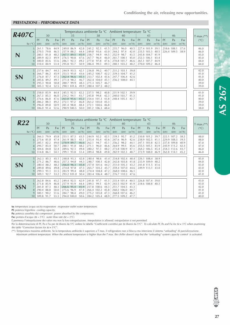
®
AS
267
27
Conditioning the air, releasing new opportunities.
PRESTAZIONI - PERFORMANCE DATA
R407C
56
SSN 789
10
56
SN 789
10
56
N 789
10
Temperatura ambiente Ta °C Ambient temperature Ta °C30 35 38 40 43 46
Pf Pa Fw Pf Pa Fw Pf Pa Fw Pf Pa Fw Pf Pa Fw Pf Pa Fwtu (°C) (kW) (kW) (m3/h) (kW) (kW) (m3/h) (kW) (kW) (m3/h) (kW) (kW) (m3/h) (kW) (kW) (m3/h) (kW) (kW) (m3/h)
261.1 78.6 44.9 249.0 86.9 42.8 241.2 92.3 41.5 235.7 96.0 40.5 227.4 101.9 39.1 218.6 108.1 37.6270.5 79.8 46.5 257.9 88.2 44.4 249.8 93.6 43.0 244.2 97.4 42.0 235.5 103.3 40.5 226.4 109.5 38.9280.1 81.0 48.2 267.1 89.5 45.9 258.7 94.9 44.5 252.9 98.7 43.5 243.8 104.7 41.9289.9 82.3 49.9 276.5 90.8 47.6 267.7 96.4 46.0 261.7 100.1 45.0 252.3 106.1 43.4300.0 83.6 51.6 286.1 92.3 49.2 277.0 97.8 47.6 270.8 101.7 46.6 261.1 107.7 44.9310.4 84.9 53.4 295.8 93.7 50.9 286.4 99.3 49.3 280.1 103.2 48.2 270.0 109.2 46.4
257.6 84.7 44.3 244.9 93.5 42.1 236.8 99.2 40.7 231.2 103.1 39.8266.7 86.2 45.9 253.5 95.0 43.6 245.2 100.7 42.2 239.3 104.7 41.2276.0 87.7 47.5 262.4 96.6 45.1 253.7 102.4 43.6 247.7 106.4 42.6285.6 89.2 49.1 271.4 98.2 46.7 262.4 104.0 45.1 256.2 108.0 44.1295.3 90.8 50.8 280.7 99.9 48.3 271.3 105.7 46.7305.3 92.4 52.5 290.1 101.6 49.9 280.4 107.5 48.2
T max.(**)(°C)
42.041.041.040.039.039.0
41.041.040.039.039.038.0
tu: temperatura acqua uscita evaporatore evaporator outlet water temperature;Pf: potenza frigorifera cooling capacity; Pa: potenza assorbita dai compressori power absorbed by the compressors;Fw: portata d’acqua (∆t = 5°C) water flow rate (∆t = 5°C).É permessa l’interpolazione dei valori ma non la loro estrapolazione. Interpolation is allowed, extrapolation is not permitted.Per la determinazione di Pf, Pa e Fw per ∆t diversi da 5°C vedere la tabella ”Coefficienti correttivi per ∆t diversi da 5°C”. To calculate Pf, Pa and Fw for ∆t ≠ 5°C when examiningthe table ”Correction factors for ∆t ≠ 5°C”.(**): Temperatura massima ambiente. Se la temperatura ambiente è superiore a T max. il refrigeratore non si blocca ma interviene il sistema “unloading” di parzializzazione.
Maximum ambient temperature. When the ambient temperature is higher than the T max. the chiller doesn’t stop but the “unloading” system capacity control is activated.
46.046.045.045.044.044.0
258.0 83.9 44.4 245.5 92.5 42.2 237.5 98.2 40.8 231.9 102.1 39.9267.3 85.3 46.0 254.2 94.1 43.7 245.8 99.8 42.3 240.0 103.7 41.3276.6 86.8 47.6 263.0 95.6 45.2 254.4 101.3 43.8 248.4 105.3 42.7286.2 88.3 49.2 272.1 97.2 46.8 263.2 103.0 45.3296.0 89.8 50.9 281.4 98.8 48.4 272.1 104.6 46.8306.0 91.4 52.6 290.9 100.5 50.0 281.2 106.3 48.4
R22
56
SSN 789
10
56
SN 789
10
56
N 789
10
Temperatura ambiente Ta °C Ambient temperature Ta °C30 35 38 40 43 46
Pf Pa Fw Pf Pa Fw Pf Pa Fw Pf Pa Fw Pf Pa Fw Pf Pa Fwtu (°C) (kW) (kW) (m3/h) (kW) (kW) (m3/h) (kW) (kW) (m3/h) (kW) (kW) (m3/h) (kW) (kW) (m3/h) (kW) (kW) (m3/h)
266.3 79.9 45.8 253.1 87.3 43.5 244.9 92.2 42.1 239.3 95.7 41.2 230.8 101.2 39.7 222.1 107.2 38.2275.6 81.0 47.4 261.9 88.5 45.1 253.4 93.4 43.6 247.6 96.9 42.6 238.9 102.5 41.1 229.9 108.5 39.5285.1 82.2 49.0 270.9 89.7 46.6 262.1 94.7 45.1 256.2 98.2 44.1 247.1 103.8 42.5 237.8 109.8 40.9294.7 83.4 50.7 280.1 91.0 48.2 271.1 96.0 46.6 264.9 99.5 45.6 255.5 105.1 43.9 245.9 111.2 42.3304.6 84.8 52.4 289.6 92.3 49.8 280.2 97.3 48.2 273.8 100.9 47.1 264.2 106.5 45.4 254.3 112.6 43.7314.8 86.1 54.1 299.1 93.8 51.4 289.4 98.8 49.8 282.9 102.3 48.7 272.9 108.0 46.9 262.8 114.1 45.2
262.3 85.3 45.1 248.8 93.3 42.8 240.4 98.6 41.4 234.8 102.4 40.4 226.1 108.4 38.9271.2 86.7 46.6 257.3 94.8 44.3 248.7 100.1 42.8 242.8 103.8 41.8 233.9 109.9 40.2280.4 88.2 48.2 266.0 96.3 45.8 257.0 101.6 44.2 251.0 105.3 43.2 241.8 111.5 41.6289.8 89.6 49.8 274.8 97.8 47.3 265.7 103.2 45.7 259.4 107.0 44.6 249.9 113.1 43.0299.3 91.1 51.5 283.9 99.4 48.8 274.4 104.8 47.2 268.0 108.6 46.1309.1 92.7 53.2 293.2 101.0 50.4 283.4 106.4 48.7 276.7 110.3 47.6
T max.(**)(°C)
45.044.043.043.042.041.0
43.043.042.041.041.040.0
48.048.047.047.046.046.0
262.8 84.6 45.2 249.4 92.5 42.9 241.0 97.7 41.5 235.4 101.4 40.5 226.8 107.4 39.0271.8 85.9 46.8 257.9 93.9 44.4 249.3 99.1 42.9 243.5 102.9 41.9 234.6 108.8 40.3281.0 87.3 48.3 266.6 95.4 45.9 257.8 100.6 44.3 251.7 104.5 43.3290.4 88.8 50.0 275.6 96.9 47.4 266.4 102.2 45.8 260.2 106.0 44.7300.1 90.2 51.6 284.7 98.4 49.0 275.2 103.8 47.3 268.8 107.6 46.2309.8 91.7 53.3 294.0 100.0 50.6 284.2 105.4 48.9 277.5 109.2 47.7
EASYY000BD_V 07-04-2006 12.14 Pagina 27
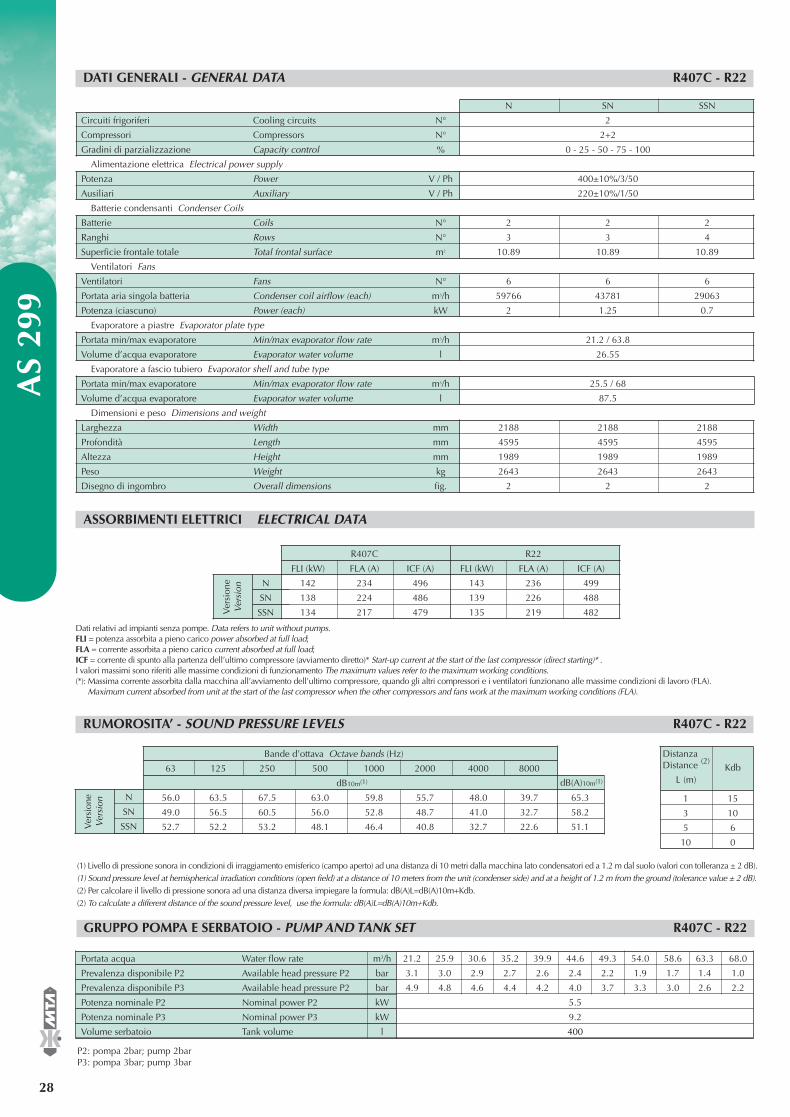
N
SN
SSN
N SN SSN
Circuiti frigoriferi Cooling circuits N° 2
Compressori Compressors N° 2+2
Gradini di parzializzazione Capacity control % 0 - 25 - 50 - 75 - 100
Alimentazione elettrica Electrical power supply
Potenza Power V / Ph 400±10%/3/50
Ausiliari Auxiliary V / Ph 220±10%/1/50
Batterie condensanti Condenser Coils
Batterie Coils N° 2 2 2
Ranghi Rows N° 3 3 4
Superficie frontale totale Total frontal surface m2 10.89 10.89 10.89
Ventilatori Fans
Ventilatori Fans N° 6 6 6
Portata aria singola batteria Condenser coil airflow (each) m3/h 59766 43781 29063
Potenza (ciascuno) Power (each) kW 2 1.25 0.7
Evaporatore a piastre Evaporator plate type
Portata min/max evaporatore Min/max evaporator flow rate m3/h 21.2 / 63.8
Volume d’acqua evaporatore Evaporator water volume l 26.55
Evaporatore a fascio tubiero Evaporator shell and tube type
Portata min/max evaporatore Min/max evaporator flow rate m3/h 25.5 / 68
Volume d’acqua evaporatore Evaporator water volume l 87.5
Dimensioni e peso Dimensions and weight
Larghezza Width mm 2188 2188 2188
Profondità Length mm 4595 4595 4595
Altezza Height mm 1989 1989 1989
Peso Weight kg 2643 2643 2643
Disegno di ingombro Overall dimensions fig. 2 2 2
PRESTAZIONI E DATI TECNICI - PERFORMANCE AND TECHNICAL DATA A
S 29
9
28
®
DATI GENERALI - GENERAL DATA R407C - R22
ASSORBIMENTI ELETTRICI ELECTRICAL DATA
R407C R22
FLI (kW) FLA (A) ICF (A) FLI (kW) FLA (A) ICF (A)
142 234 496 143 236 499
138 224 486 139 226 488
134 217 479 135 219 482Ver
sion
eV
ersi
on
Dati relativi ad impianti senza pompe. Data refers to unit without pumps.FLI = potenza assorbita a pieno carico power absorbed at full load; FLA = corrente assorbita a pieno carico current absorbed at full load;ICF = corrente di spunto alla partenza dell’ultimo compressore (avviamento diretto)* Start-up current at the start of the last compressor (direct starting)* . I valori massimi sono riferiti alle massime condizioni di funzionamento The maximum values refer to the maximum working conditions.(*): Massima corrente assorbita dalla macchina all’avviamento dell’ultimo compressore, quando gli altri compressori e i ventilatori funzionano alle massime condizioni di lavoro (FLA).
Maximum current absorbed from unit at the start of the last compressor when the other compressors and fans work at the maximum working conditions (FLA).
RUMOROSITA’ - SOUND PRESSURE LEVELS R407C - R22
1 15
3 10
5 6
10 0
DistanzaDistance (2)
L (m)Kdb
(1) Livello di pressione sonora in condizioni di irraggiamento emisferico (campo aperto) ad una distanza di 10 metri dalla macchina lato condensatori ed a 1.2 m dal suolo (valori con tolleranza ± 2 dB). (1) Sound pressure level at hemispherical irradiation conditions (open field) at a distance of 10 meters from the unit (condenser side) and at a height of 1.2 m from the ground (tolerance value ± 2 dB). (2) Per calcolare il livello di pressione sonora ad una distanza diversa impiegare la formula: dB(A)L=dB(A)10m+Kdb. (2) To calculate a different distance of the sound pressure level, use the formula: dB(A)L=dB(A)10m+Kdb.
GRUPPO POMPA E SERBATOIO - PUMP AND TANK SET R407C - R22
21.2 25.9 30.6 35.2 39.9 44.6 49.3 54.0 58.6 63.3 68.0
3.1 3.0 2.9 2.7 2.6 2.4 2.2 1.9 1.7 1.4 1.0
4.9 4.8 4.6 4.4 4.2 4.0 3.7 3.3 3.0 2.6 2.2
5.5
9.2
400
P2: pompa 2bar; pump 2barP3: pompa 3bar; pump 3bar
Portata acqua Water flow rate m3/h
Prevalenza disponibile P2 Available head pressure P2 bar
Prevalenza disponibile P3 Available head pressure P2 bar
Potenza nominale P2 Nominal power P2 kW
Potenza nominale P3 Nominal power P3 kW
Volume serbatoio Tank volume l
N
SN
SSN
Bande d’ottava Octave bands (Hz)
63 125 250 500 1000 2000 4000 8000
dB10m(1)
56.0 63.5 67.5 63.0 59.8 55.7 48.0 39.7 65.3
49.0 56.5 60.5 56.0 52.8 48.7 41.0 32.7 58.2
52.7 52.2 53.2 48.1 46.4 40.8 32.7 22.6 51.1Ver
sion
eV
ersi
on
dB(A)10m(1)
EASYY000BD_V 07-04-2006 12.14 Pagina 28

®
AS
299
29
Conditioning the air, releasing new opportunities.
PRESTAZIONI - PERFORMANCE DATA
R407C
56
SSN 789
10
56
SN 789
10
56
N 789
10
Temperatura ambiente Ta °C Ambient temperature Ta °C30 35 38 40 43 46
Pf Pa Fw Pf Pa Fw Pf Pa Fw Pf Pa Fw Pf Pa Fw Pf Pa Fwtu (°C) (kW) (kW) (m3/h) (kW) (kW) (m3/h) (kW) (kW) (m3/h) (kW) (kW) (m3/h) (kW) (kW) (m3/h) (kW) (kW) (m3/h)
290.8 82.3 50.0 277.8 91.2 47.8 269.5 97.0 46.4 263.8 101.1 45.4 255.0 107.6 43.9 245.9 114.5 42.3301.1 83.4 51.8 287.7 92.3 49.5 279.1 98.1 48.0 273.3 102.3 47.0 264.1 108.8 45.4 254.7 115.9 43.8311.7 84.4 53.6 297.7 93.4 51.2 288.9 99.3 49.7 282.8 103.5 48.6 273.4 110.1 47.0 263.6 117.2 45.3322.4 85.5 55.5 308.1 94.6 53.0 298.9 100.6 51.4 292.6 104.8 50.3 282.9 111.4 48.7 272.8 118.6 46.9333.5 86.6 57.4 318.7 95.8 54.8 309.2 101.8 53.2 302.7 106.1 52.1 292.6 112.8 50.3344.8 87.8 59.3 329.4 97.1 56.7 319.7 103.2 55.0 313.0 107.4 53.8 302.6 114.2 52.1
287.6 88.3 49.5 274.2 97.7 47.2 265.7 104.0 45.7 259.8 108.3 44.7 250.8 115.3 43.1297.6 89.5 51.2 283.8 99.1 48.8 275.0 105.4 47.3 268.9 109.8 46.3 259.6 116.9 44.7307.9 90.8 53.0 293.6 100.5 50.5 284.5 106.8 48.9 278.3 111.3 47.9 268.7 118.5 46.2318.5 92.2 54.8 303.7 102.0 52.2 294.3 108.4 50.6 287.8 112.9 49.5 277.8 120.1 47.8329.3 93.7 56.6 314.0 103.5 54.0 304.2 109.9 52.3 297.6 114.5 51.2340.3 95.1 58.5 324.4 105.1 55.8 314.4 111.7 54.1 307.5 116.2 52.9
T max.(**)(°C)
44.044.043.043.042.042.0
42.041.040.040.039.038.0
tu: temperatura acqua uscita evaporatore evaporator outlet water temperature;Pf: potenza frigorifera cooling capacity; Pa: potenza assorbita dai compressori power absorbed by the compressors;Fw: portata d’acqua (∆t = 5°C) water flow rate (∆t = 5°C).É permessa l’interpolazione dei valori ma non la loro estrapolazione. Interpolation is allowed, extrapolation is not permitted.Per la determinazione di Pf, Pa e Fw per ∆t diversi da 5°C vedere la tabella ”Coefficienti correttivi per ∆t diversi da 5°C”. To calculate Pf, Pa and Fw for ∆t ≠ 5°C when examiningthe table ”Correction factors for ∆t ≠ 5°C”.(**): Temperatura massima ambiente. Se la temperatura ambiente è superiore a T max. il refrigeratore non si blocca ma interviene il sistema “unloading” di parzializzazione.
Maximum ambient temperature. When the ambient temperature is higher than the T max. the chiller doesn’t stop but the “unloading” system capacity control is activated.
47.046.046.046.045.045.0
284.1 94.7 48.9 270.4 104.8 46.5 261.7 111.5 45.0 255.7 116.2 44.0294.0 96.2 50.6 279.7 106.5 48.1 270.7 113.2 46.6 264.5 118.0 45.5304.0 97.8 52.3 289.3 108.2 49.8 280.0 115.1 48.2 273.6 119.9 47.1314.3 99.4 54.1 299.0 110.0 51.4 289.4 116.9 49.8 282.8 121.8 48.6324.8 101.2 55.9 309.0 111.8 53.1 299.0 118.8 51.4335.5 102.9 57.7 319.2 113.7 54.9 308.9 120.7 53.1
R22
56
SSN 789
10
56
SN 789
10
56
N 789
10
Temperatura ambiente Ta °C Ambient temperature Ta °C30 35 38 40 43 46
Pf Pa Fw Pf Pa Fw Pf Pa Fw Pf Pa Fw Pf Pa Fw Pf Pa Fwtu (°C) (kW) (kW) (m3/h) (kW) (kW) (m3/h) (kW) (kW) (m3/h) (kW) (kW) (m3/h) (kW) (kW) (m3/h) (kW) (kW) (m3/h)
296.1 83.2 50.9 282.3 91.0 48.6 273.7 96.2 47.1 267.8 99.9 46.1 259.0 105.7 44.5 249.8 112.0 43.0306.4 84.2 52.7 292.1 92.1 50.2 283.2 97.3 48.7 277.2 101.0 47.7 267.9 106.9 46.1 258.4 113.2 44.4317.0 85.3 54.5 302.2 93.2 52.0 293.1 98.4 50.4 286.8 102.1 49.3 277.2 108.0 47.7 267.5 114.4 46.0327.8 86.4 56.4 312.6 94.3 53.8 303.1 99.6 52.1 296.6 103.3 51.0 286.8 109.3 49.3 276.6 115.7 47.6338.9 87.5 58.3 323.1 95.5 55.6 313.3 100.8 53.9 306.7 104.5 52.7 296.5 110.5 51.0 286.1 116.9 49.2350.2 88.6 60.2 334.0 96.7 57.4 323.9 102.0 55.7 317.0 105.8 54.5 306.5 111.8 52.7 295.8 118.3 50.9
292.6 88.5 50.3 278.6 96.9 47.9 269.8 102.5 46.4 263.9 106.4 45.4 254.7 112.7 43.8 245.4 119.6 42.2302.8 89.7 52.1 288.2 98.2 49.6 279.2 103.8 48.0 273.0 107.8 47.0 263.6 114.1 45.3 254.0 121.0 43.7313.1 91.0 53.9 298.1 99.5 51.3 288.7 105.1 49.7 282.4 109.1 48.6 272.7 115.5 46.9323.6 92.3 55.7 308.1 100.9 53.0 298.5 106.5 51.3 291.9 110.6 50.2 281.9 117.0 48.5334.5 93.6 57.5 318.4 102.3 54.8 308.4 108.0 53.1 301.7 112.0 51.9 291.4 118.5 50.1345.5 95.0 59.4 329.0 103.8 56.6 318.7 109.5 54.8 311.7 113.6 53.6 301.0 120.1 51.8
T max.(**)(°C)
46.046.045.045.044.044.0
43.042.042.041.040.040.0
49.049.048.048.047.047.0
289.1 94.2 49.7 274.8 103.3 47.3 265.9 109.2 45.7 259.8 113.5 44.7 250.6 120.3 43.1299.0 95.7 51.4 284.1 104.8 48.9 275.0 110.8 47.3 268.8 115.1 46.2309.1 97.2 53.2 293.8 106.3 50.5 284.3 112.4 48.9 277.8 116.8 47.8319.4 98.7 54.9 303.5 107.9 52.2 293.8 114.1 50.5 287.1 118.4 49.4329.9 100.3 56.7 313.6 109.6 53.9 303.5 115.8 52.2 296.6 120.2 51.0340.6 101.9 58.6 323.8 111.3 55.7 313.4 117.6 53.9 306.3 122.0 52.7
EASYY000BD_V 07-04-2006 12.14 Pagina 29

N
SN
SSN
N SN SSN
Circuiti frigoriferi Cooling circuits N° 2
Compressori Compressors N° 2+2
Gradini di parzializzazione Capacity control % 0 - 25 - 50 - 75 - 100
Alimentazione elettrica Electrical power supply
Potenza Power V / Ph 400±10%/3/50
Ausiliari Auxiliary V / Ph 220±10%/1/50
Batterie condensanti Condenser Coils
Batterie Coils N° 2 2 2
Ranghi Rows N° 3 3 4
Superficie frontale totale Total frontal surface m2 10.89 10.89 10.89
Ventilatori Fans
Ventilatori Fans N° 6 6 6
Portata aria singola batteria Condenser coil airflow (each) m3/h 59766 43781 29063
Potenza (ciascuno) Power (each) kW 2 1.25 0.7
Evaporatore a piastre Evaporator plate type
Portata min/max evaporatore Min/max evaporator flow rate m3/h 22.8 / 68.3
Volume d’acqua evaporatore Evaporator water volume l 30.15
Evaporatore a fascio tubiero Evaporator shell and tube type
Portata min/max evaporatore Min/max evaporator flow rate m3/h 27.3 / 68
Volume d’acqua evaporatore Evaporator water volume l 87.5
Dimensioni e peso Dimensions and weight
Larghezza Width mm 2188 2188 2188
Profondità Length mm 4595 4595 4595
Altezza Height mm 1989 1989 1989
Peso Weight kg 2723 2723 2723
Disegno di ingombro Overall dimensions fig. 2 2 2
PRESTAZIONI E DATI TECNICI - PERFORMANCE AND TECHNICAL DATA A
S 31
9
30
®
DATI GENERALI - GENERAL DATA R407C - R22
ASSORBIMENTI ELETTRICI ELECTRICAL DATA
R407C R22
FLI (kW) FLA (A) ICF (A) FLI (kW) FLA (A) ICF (A)
156 255 517 156 255 517
152 245 507 152 245 507
148 238 500 148 238 500Ver
sion
eV
ersi
on
Dati relativi ad impianti senza pompe. Data refers to unit without pumps.FLI = potenza assorbita a pieno carico power absorbed at full load; FLA = corrente assorbita a pieno carico current absorbed at full load;ICF = corrente di spunto alla partenza dell’ultimo compressore (avviamento diretto)* Start-up current at the start of the last compressor (direct starting)* . I valori massimi sono riferiti alle massime condizioni di funzionamento The maximum values refer to the maximum working conditions.(*): Massima corrente assorbita dalla macchina all’avviamento dell’ultimo compressore, quando gli altri compressori e i ventilatori funzionano alle massime condizioni di lavoro (FLA).
Maximum current absorbed from unit at the start of the last compressor when the other compressors and fans work at the maximum working conditions (FLA).
RUMOROSITA’ - SOUND PRESSURE LEVELS R407C - R22
1 15
3 10
5 6
10 0
DistanzaDistance (2)
L (m)Kdb
(1) Livello di pressione sonora in condizioni di irraggiamento emisferico (campo aperto) ad una distanza di 10 metri dalla macchina lato condensatori ed a 1.2 m dal suolo (valori con tolleranza ± 2 dB). (1) Sound pressure level at hemispherical irradiation conditions (open field) at a distance of 10 meters from the unit (condenser side) and at a height of 1.2 m from the ground (tolerance value ± 2 dB). (2) Per calcolare il livello di pressione sonora ad una distanza diversa impiegare la formula: dB(A)L=dB(A)10m+Kdb. (2) To calculate a different distance of the sound pressure level, use the formula: dB(A)L=dB(A)10m+Kdb.
GRUPPO POMPA E SERBATOIO - PUMP AND TANK SET R407C - R22
22.8 27.3 31.8 36.4 40.9 45.4 49.9 54.4 59.0 63.5 68.0
3.1 3.0 2.9 2.7 2.6 2.4 2.2 1.9 1.7 1.4 1.1
4.9 4.7 4.6 4.4 4.2 3.9 3.7 3.4 3.0 2.6 2.2
5.5
9.2
400
P2: pompa 2bar; pump 2barP3: pompa 3bar; pump 3bar
Portata acqua Water flow rate m3/h
Prevalenza disponibile P2 Available head pressure P2 bar
Prevalenza disponibile P3 Available head pressure P2 bar
Potenza nominale P2 Nominal power P2 kW
Potenza nominale P3 Nominal power P3 kW
Volume serbatoio Tank volume l
N
SN
SSN
Bande d’ottava Octave bands (Hz)
63 125 250 500 1000 2000 4000 8000
dB10m(1)
56.0 63.5 67.5 63.0 59.8 55.7 48.0 39.7 65.3
49.0 56.5 60.5 56.0 52.8 48.7 41.0 32.7 58.2
52.7 52.2 53.2 48.1 46.4 40.8 32.7 22.6 51.1Ver
sion
eV
ersi
on
dB(A)10m(1)
EASYY000BD_V 07-04-2006 12.14 Pagina 30
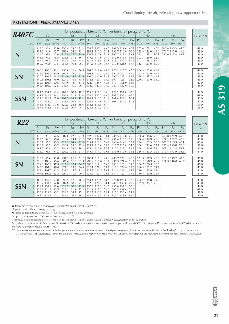
®
AS
319
31
Conditioning the air, releasing new opportunities.
PRESTAZIONI - PERFORMANCE DATA
R407C
56
SSN 789
10
56
SN 789
10
56
N 789
10
Temperatura ambiente Ta °C Ambient temperature Ta °C30 35 38 40 43 46
Pf Pa Fw Pf Pa Fw Pf Pa Fw Pf Pa Fw Pf Pa Fw Pf Pa Fwtu (°C) (kW) (kW) (m3/h) (kW) (kW) (m3/h) (kW) (kW) (m3/h) (kW) (kW) (m3/h) (kW) (kW) (m3/h) (kW) (kW) (m3/h)
313.0 93.4 53.8 298.4 103.3 51.3 289.2 109.9 49.7 282.9 114.6 48.7 273.4 122.1 47.0 263.6 130.3 45.3323.8 94.6 55.7 308.6 104.6 53.1 299.1 111.2 51.4 292.7 116.0 50.3 282.8 123.6 48.6 272.7 131.8 46.9334.7 95.8 57.6 319.0 105.9 54.9 309.3 112.6 53.2 302.7 117.4 52.1 292.4 125.1 50.3 282.0 133.4 48.5345.9 97.0 59.5 329.8 107.2 56.7 319.8 114.0 55.0 312.9 118.9 53.8 302.3 126.6 52.0357.4 98.3 61.5 340.8 108.6 58.6 330.3 115.5 56.8 323.2 120.4 55.6 312.4 128.2 53.7369.2 99.6 63.5 351.9 110.1 60.5 341.2 117.0 58.7 333.8 121.9 57.4 322.7 129.8 55.5
308.8 100.6 53.1 293.8 111.4 50.5 284.5 118.6 48.9 278.1 123.7 47.8 268.3 132.0 46.2319.3 102.0 54.9 303.8 113.0 52.2 294.1 120.2 50.6 287.5 125.5 49.5 277.5 133.8 47.7330.0 103.6 56.8 314.0 114.6 54.0 304.0 122.0 52.3 297.2 127.2 51.1 286.8 135.7 49.3340.9 105.1 58.6 324.3 116.3 55.8 314.1 123.7 54.0 307.1 129.1 52.8 296.3 137.6 51.0352.0 106.7 60.5 334.9 118.0 57.6 324.4 125.6 55.8 317.1 131.0 54.5363.4 108.5 62.5 345.8 119.8 59.5 334.9 127.5 57.6 327.4 132.9 56.3
T max.(**)(°C)
44.044.043.043.042.041.0
42.041.040.040.039.038.0
tu: temperatura acqua uscita evaporatore evaporator outlet water temperature;Pf: potenza frigorifera cooling capacity; Pa: potenza assorbita dai compressori power absorbed by the compressors;Fw: portata d’acqua (∆t = 5°C) water flow rate (∆t = 5°C).É permessa l’interpolazione dei valori ma non la loro estrapolazione. Interpolation is allowed, extrapolation is not permitted.Per la determinazione di Pf, Pa e Fw per ∆t diversi da 5°C vedere la tabella ”Coefficienti correttivi per ∆t diversi da 5°C”. To calculate Pf, Pa and Fw for ∆t ≠ 5°C when examiningthe table ”Correction factors for ∆t ≠ 5°C”.(**): Temperatura massima ambiente. Se la temperatura ambiente è superiore a T max. il refrigeratore non si blocca ma interviene il sistema “unloading” di parzializzazione.
Maximum ambient temperature. When the ambient temperature is higher than the T max. the chiller doesn’t stop but the “unloading” system capacity control is activated.
47.046.046.045.045.045.0
304.5 108.4 52.4 289.1 120.2 49.7 279.6 128.1 48.1 273.1 133.8 47.0314.7 110.2 54.1 298.8 122.1 51.4 288.9 130.2 49.7 282.3 135.9 48.6325.0 112.1 55.9 308.7 124.3 53.1 298.5 132.2 51.3 291.6 138.1 50.1335.7 114.0 57.7 318.8 126.2 54.8 308.2 134.6 53.0 301.2 140.3 51.8346.5 116.0 59.6 329.0 128.5 56.6 318.2 136.8 54.7357.5 118.1 61.5 339.5 130.7 58.4 328.3 139.2 56.5
R22
56
SSN 789
10
56
SN 789
10
56
N 789
10
Temperatura ambiente Ta °C Ambient temperature Ta °C30 35 38 40 43 46
Pf Pa Fw Pf Pa Fw Pf Pa Fw Pf Pa Fw Pf Pa Fw Pf Pa Fwtu (°C) (kW) (kW) (m3/h) (kW) (kW) (m3/h) (kW) (kW) (m3/h) (kW) (kW) (m3/h) (kW) (kW) (m3/h) (kW) (kW) (m3/h)
316.8 93.1 54.5 302.0 102.0 51.9 292.8 107.8 50.4 286.5 112.0 49.3 276.8 118.6 47.6 267.0 125.9 45.9327.6 94.2 56.4 312.4 103.1 53.7 302.9 109.0 52.1 296.4 113.2 51.0 286.4 119.9 49.3 276.2 127.2 47.5338.7 95.3 58.3 322.9 104.4 55.5 313.1 110.3 53.9 306.4 114.5 52.7 296.2 121.3 50.9 285.7 128.5 49.1350.1 96.5 60.2 333.8 105.6 57.4 323.7 111.6 55.7 316.7 115.8 54.5 306.2 122.6 52.7 295.4 130.0 50.8361.7 97.8 62.2 344.9 106.9 59.3 334.4 112.9 57.5 327.3 117.2 56.3 316.4 124.0 54.4 305.3 131.4 52.5373.5 99.0 64.2 356.2 108.2 61.3 345.4 114.3 59.4 338.0 118.6 58.1 326.8 125.5 56.2 315.4 132.9 54.2
312.6 99.6 53.8 297.5 109.2 51.2 288.1 115.5 49.6 281.7 120.1 48.5 271.9 127.3 46.8 261.9 135.2 45.0323.2 100.9 55.6 307.6 110.6 52.9 297.9 117.0 51.2 291.3 121.6 50.1 281.2 128.9 48.4 270.9 136.8 46.6334.1 102.3 57.5 317.9 112.1 54.7 308.0 118.5 53.0 301.1 123.2 51.8 290.7 130.5 50.0345.1 103.8 59.4 328.5 113.6 56.5 318.1 120.1 54.7 311.1 124.8 53.5 300.3 132.2 51.7356.4 105.2 61.3 339.2 115.2 58.3 328.5 121.7 56.5 321.3 126.4 55.3 310.2 133.9 53.4367.9 106.9 63.3 350.2 116.8 60.2 339.2 123.4 58.3 331.7 128.1 57.1 320.3 135.6 55.1
T max.(**)(°C)
46.046.045.045.044.044.0
44.043.042.042.041.040.0
49.048.048.048.047.047.0
308.4 106.5 53.0 292.9 117.0 50.4 283.4 123.9 48.7 276.8 128.8 47.6 266.9 136.8 45.9318.7 108.2 54.8 302.8 118.7 52.1 292.9 125.7 50.4 286.1 130.6 49.2 275.9 138.7 47.5329.1 109.9 56.6 312.7 120.6 53.8 302.5 127.5 52.0 295.6 132.5 50.8339.9 111.7 58.5 322.9 122.4 55.5 312.4 129.5 53.7 305.3 134.4 52.5350.9 113.4 60.3 333.3 124.3 57.3 322.5 131.5 55.5 315.1 136.6 54.2362.0 115.3 62.3 344.0 126.2 59.2 332.7 133.5 57.2 325.2 138.6 55.9
EASYY000BD_V 07-04-2006 12.14 Pagina 31
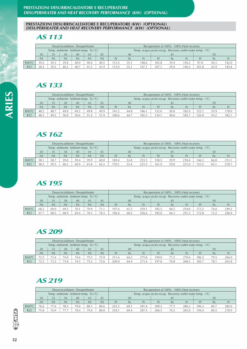
PRESTAZIONI DESURRISCALDATORE E RECUPERATOREDESUPERHEATER AND HEAT RECOVERY PERFORMANCE (KW) (OPTIONAL)
AR
IES
32
®
Desurriscaldatore Desuperheater Recuperatore al 100% 100% Heat recoveryTemp. ambiente Ambient temp. Ta (°C) Temp. acqua uscita recup. Recovery outlet water temp. (°C)
30 35 38 40 43 45 40 45 50Pd Pd Pd Pd Pd Pd Pf Pa Pr Pf Pa Pr Pf Pa Pr
R407C 39.2 39.5 39.8 40.0 40.4 40.5 113.4 35.1 148.6 105.8 39.4 145.2 97.8 44.3 142.0R22 38.4 39.5 40.2 40.7 41.5 41.9 112.0 35.1 147.1 107.1 39.4 146.5 101.8 43.9 145.8
PRESTAZIONI DESURRISCALDATORE E RECUPERATORE (KW) (OPTIONAL)DESUPERHEATER AND HEAT RECOVERY PERFORMANCE (KW) (OPTIONAL)
AS 113
Desurriscaldatore Desuperheater Recuperatore al 100% 100% Heat recoveryTemp. ambiente Ambient temp. Ta (°C) Temp. acqua uscita recup. Recovery outlet water temp. (°C)
30 35 38 40 43 45 40 45 50Pd Pd Pd Pd Pd Pd Pf Pa Pr Pf Pa Pr Pf Pa Pr
R407C 48.2 48.7 49.0 49.3 49.8 49.9 141.2 44.8 186.1 132.0 50.0 182.0 122.1 55.9 178.0R22 48.2 49.3 50.0 50.6 51.4 51.9 140.6 44.7 185.3 134.1 49.6 183.7 126.9 55.2 182.1
AS 133
Desurriscaldatore Desuperheater Recuperatore al 100% 100% Heat recoveryTemp. ambiente Ambient temp. Ta (°C) Temp. acqua uscita recup. Recovery outlet water temp. (°C)
30 35 38 40 43 45 40 45 50Pd Pd Pd Pd Pd Pd Pf Pa Pr Pf Pa Pr Pf Pa Pr
R407C 58.1 58.7 59.0 59.4 59.9 60.0 169.4 53.8 223.3 158.5 59.9 218.4 146.3 66.8 213.1R22 58.3 59.5 60.2 60.9 61.8 62.3 170.1 53.4 223.5 161.9 59.0 221.0 153.5 65.1 218.7
AS 162
Desurriscaldatore Desuperheater Recuperatore al 100% 100% Heat recoveryTemp. ambiente Ambient temp. Ta (°C) Temp. acqua uscita recup. Recovery outlet water temp. (°C)
30 35 38 40 43 45 40 45 50Pd Pd Pd Pd Pd Pd Pf Pa Pr Pf Pa Pr Pf Pa Pr
R407C 68.2 69.0 69.5 70.1 70.9 71.1 197.6 61.5 259.1 185.5 68.5 254.0 173.2 76.0 249.2R22 67.7 68.5 68.9 69.4 70.1 70.3 196.4 60.2 256.6 185.0 66.3 251.3 172.8 73.2 246.0
AS 195
Desurriscaldatore Desuperheater Recuperatore al 100% 100% Heat recoveryTemp. ambiente Ambient temp. Ta (°C) Temp. acqua uscita recup. Recovery outlet water temp. (°C)
30 35 38 40 43 45 40 45 50Pd Pd Pd Pd Pd Pd Pf Pa Pr Pf Pa Pr Pf Pa Pr
R407C 72.5 73.4 74.0 74.6 75.5 75.9 211.6 64.2 275.8 199.0 71.5 270.6 186.5 79.5 266.0R22 72.2 73.2 73.8 74.3 75.2 75.6 209.0 64.4 273.4 197.8 70.8 268.5 185.7 78.1 263.8
AS 209
Desurriscaldatore Desuperheater Recuperatore al 100% 100% Heat recoveryTemp. ambiente Ambient temp. Ta (°C) Temp. acqua uscita recup. Recovery outlet water temp. (°C)
30 35 38 40 43 45 40 45 50Pd Pd Pd Pd Pd Pd Pf Pa Pr Pf Pa Pr Pf Pa Pr
R407C 76.6 77.6 78.3 79.0 80.1 80.6 222.3 69.1 291.4 209.2 77.1 286.2 196.3 85.7 282.0R22 75.8 76.9 77.7 78.4 79.4 80.0 218.1 69.4 287.5 206.5 76.5 283.0 194.4 84.5 278.9
AS 219
EASYY000BD_V 07-04-2006 12.14 Pagina 32
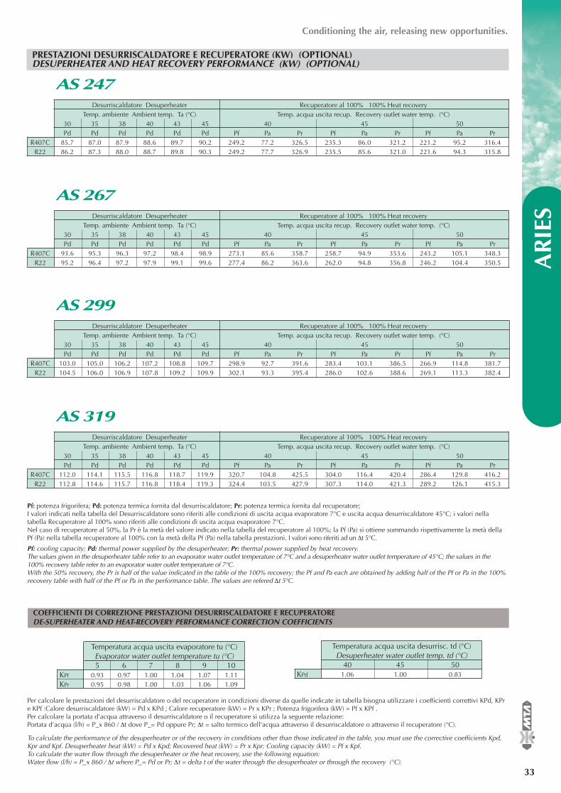
®
AR
IES
33
Pf: potenza frigorifera; Pd: potenza termica fornita dal desurriscaldatore; Pr: potenza termica fornita dal recuperatore;I valori indicati nella tabella del Desurriscaldatore sono riferiti alle condizioni di uscita acqua evaporatore 7°C e uscita acqua desurriscaldatore 45°C; i valori nellatabella Recuperatore al 100% sono riferiti alle condizioni di uscita acqua evaporatore 7°C.Nel caso di recuperatore al 50%, la Pr è la metà del valore indicato nella tabella del recuperatore al 100%; la Pf (Pa) si ottiene sommando rispettivamente la metà dellaPf (Pa) nella tabella recuperatore al 100% con la metà della Pf (Pa) nella tabella prestazioni. I valori sono riferiti ad un ∆t 5°C.
Pf: cooling capacity; Pd: thermal power supplied by the desuperheater; Pr: thermal power supplied by heat recovery.The values given in the desuperheater table refer to an evaporator water outlet temperature of 7°C and a desuperheater water outlet temperature of 45°C; the values in the100% recovery table refer to an evaporator water outlet temperature of 7°C.With the 50% recovery, the Pr is half of the value indicated in the table of the 100% recovery; the Pf and Pa each are obtained by adding half of the Pf or Pa in the 100%recovery table with half of the Pf or Pa in the performance table. The values are refered ∆t 5°C.
PRESTAZIONI DESURRISCALDATORE E RECUPERATORE (KW) (OPTIONAL)DESUPERHEATER AND HEAT RECOVERY PERFORMANCE (KW) (OPTIONAL)
Conditioning the air, releasing new opportunities.
Temperatura acqua uscita evaporatore tu (°C)Evaporator water outlet temperature tu (°C)5 6 7 8 9 10
KPf 0.93 0.97 1.00 1.04 1.07 1.11KPr 0.95 0.98 1.00 1.03 1.06 1.09
Per calcolare le prestazioni del desurriscaldatore o del recuperatore in condizioni diverse da quelle indicate in tabella bisogna utilizzare i coefficienti correttivi KPd, KPre KPf :Calore desurriscaldatore (kW) = Pd x KPd ; Calore recuperatore (kW) = Pr x KPr ; Potenza frigorifera (kW) = Pf x KPf .Per calcolare la portata d’acqua attraverso il desurriscaldatore o il recuperatore si utilizza la seguente relazione:Portata d’acqua (l/h) = P_x 860 / ∆t dove P_= Pd oppure Pr; ∆t = salto termico dell’acqua attraverso il desurriscaldatore o attraverso il recuperatore (°C).
To calculate the performance of the desuperheater or of the recovery in conditions other than those indicated in the table, you must use the corrective coefficients Kpd,Kpr and Kpf. Desuperheater heat (kW) = Pd x Kpd; Recovered heat (kW) = Pr x Kpr; Cooling capacity (kW) = Pf x Kpf.To calculate the water flow through the desuperheater or the heat recovery, use the following equation:Water flow (l/h) = P_x 860 / ∆t where P_= Pd or Pr; ∆t = delta t of the water through the desuperheater or through the recovery (°C).
Temperatura acqua uscita desurrisc. td (°C)Desuperheater water outlet temp. td (°C)
40 45 50KPd 1.06 1.00 0.83
Desurriscaldatore Desuperheater Recuperatore al 100% 100% Heat recoveryTemp. ambiente Ambient temp. Ta (°C) Temp. acqua uscita recup. Recovery outlet water temp. (°C)
30 35 38 40 43 45 40 45 50Pd Pd Pd Pd Pd Pd Pf Pa Pr Pf Pa Pr Pf Pa Pr
R407C 85.7 87.0 87.9 88.6 89.7 90.2 249.2 77.2 326.5 235.3 86.0 321.2 221.2 95.2 316.4R22 86.2 87.3 88.0 88.7 89.8 90.3 249.2 77.7 326.9 235.5 85.6 321.0 221.6 94.3 315.8
AS 247
Desurriscaldatore Desuperheater Recuperatore al 100% 100% Heat recoveryTemp. ambiente Ambient temp. Ta (°C) Temp. acqua uscita recup. Recovery outlet water temp. (°C)
30 35 38 40 43 45 40 45 50Pd Pd Pd Pd Pd Pd Pf Pa Pr Pf Pa Pr Pf Pa Pr
R407C 93.6 95.3 96.3 97.2 98.4 98.9 273.1 85.6 358.7 258.7 94.9 353.6 243.2 105.1 348.3R22 95.2 96.4 97.2 97.9 99.1 99.6 277.4 86.2 363.6 262.0 94.8 356.8 246.2 104.4 350.5
AS 267
Desurriscaldatore Desuperheater Recuperatore al 100% 100% Heat recoveryTemp. ambiente Ambient temp. Ta (°C) Temp. acqua uscita recup. Recovery outlet water temp. (°C)
30 35 38 40 43 45 40 45 50Pd Pd Pd Pd Pd Pd Pf Pa Pr Pf Pa Pr Pf Pa Pr
R407C 103.0 105.0 106.2 107.2 108.8 109.7 298.9 92.7 391.6 283.4 103.1 386.5 266.9 114.8 381.7R22 104.5 106.0 106.9 107.8 109.2 109.9 302.1 93.3 395.4 286.0 102.6 388.6 269.1 113.3 382.4
AS 299
Desurriscaldatore Desuperheater Recuperatore al 100% 100% Heat recoveryTemp. ambiente Ambient temp. Ta (°C) Temp. acqua uscita recup. Recovery outlet water temp. (°C)
30 35 38 40 43 45 40 45 50Pd Pd Pd Pd Pd Pd Pf Pa Pr Pf Pa Pr Pf Pa Pr
R407C 112.0 114.1 115.5 116.8 118.7 119.9 320.7 104.8 425.5 304.0 116.4 420.4 286.4 129.8 416.2R22 112.8 114.6 115.7 116.8 118.4 119.3 324.4 103.5 427.9 307.3 114.0 421.3 289.2 126.1 415.3
AS 319
COEFFICIENTI DI CORREZIONE PRESTAZIONI DESURRISCALDATORE E RECUPERATOREDE-SUPERHEATER AND HEAT-RECOVERY PERFORMANCE CORRECTION COEFFICIENTS
EASYY000BD_V 07-04-2006 12.14 Pagina 33
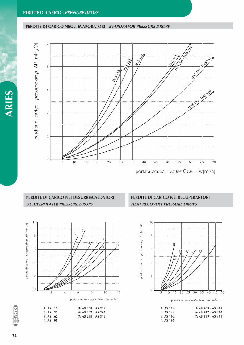
PERDITE DI CARICO - PRESSURE DROPSA
RIE
S
34
®
0
2
4
6
8
10
HA
S 11
3 HA
S 13
3
HAS
162
HAS
195
HAS
209
- H
AS 2
19HAS 2
47 -
HAS 267
5 10 15 20 25 30 35 40 45 50 55 60 65 70
HAS 299 - H
AS 319
portata acqua - water flow Fw[m3/h]
perd
ita d
i car
ico
pr
essu
re d
rop∆
P [m
H2O
]
PERDITE DI CARICO NEGLI EVAPORATORI - EVAPORATOR PRESSURE DROPS
PERDITE DI CARICO NEI DESURRISCALDATORI
DESUPERHEATER PRESSURE DROPS
PERDITE DI CARICO NEI RECUPERARTORI
HEAT RECOVERY PRESSURE DROPS
0
2
4
6
8
10
2 10
12
34
56
7
4 6 8 120
2
4
6
8
10
5 45
1
15 25 3510 5020 30 40
2
3 4 5
7
6
perd
ita d
i car
ico
pr
essu
re d
rop∆
P [m
H2O
]
portata acqua - water flow Fw [m3/h] portata acqua - water flow Fw [m3/h]
perd
ita d
i car
ico
pr
essu
re d
rop∆
P [m
H2O
]
1: AS 113 5: AS 209 - AS 219 2: AS 133 6: AS 247 - AS 2673: AS 162 7: AS 299 - AS 3194: AS 195
1: AS 113 5: AS 209 - AS 219 2: AS 133 6: AS 247 - AS 2673: AS 162 7: AS 299 - AS 3194: AS 195
EASYY000BD_V 07-04-2006 12.15 Pagina 34
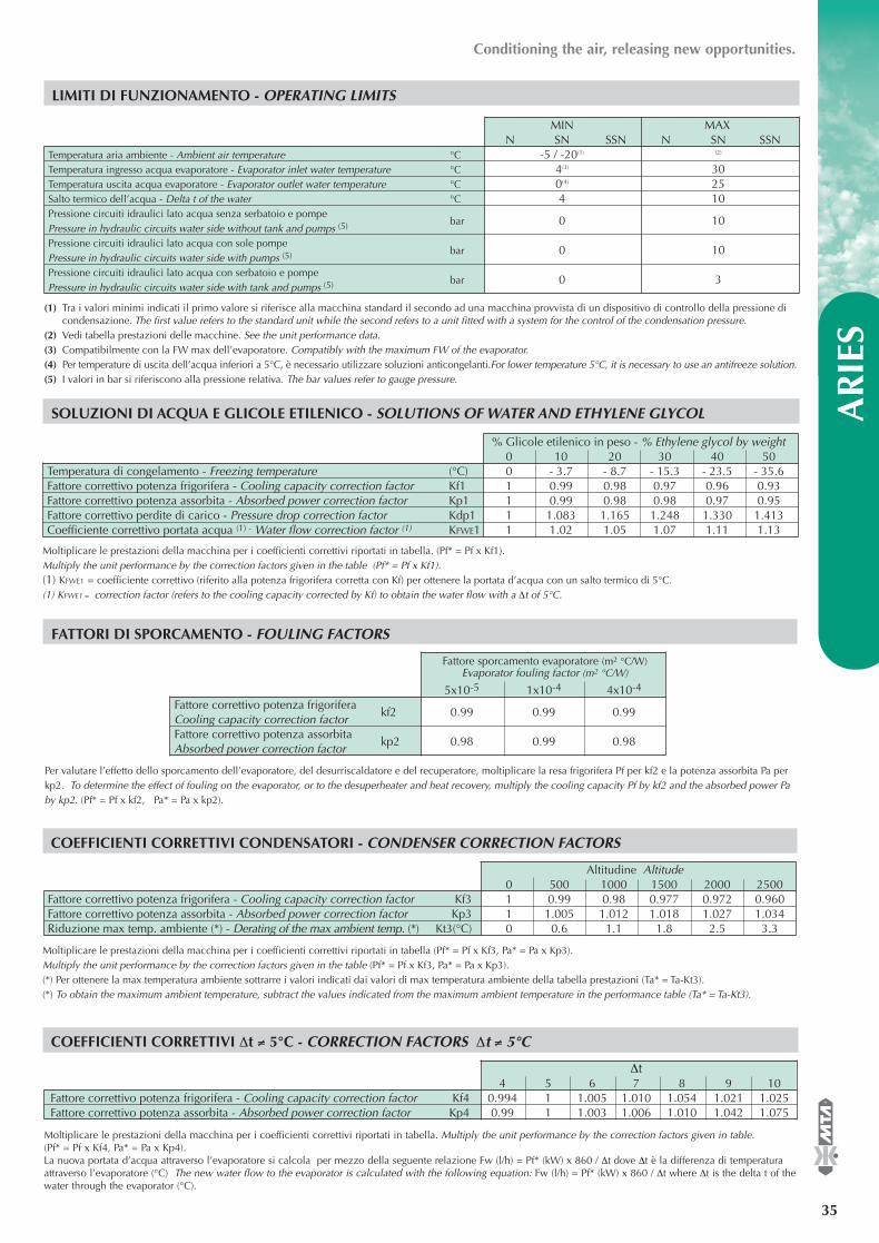
®
AR
IES
35
Conditioning the air, releasing new opportunities.
SOLUZIONI DI ACQUA E GLICOLE ETILENICO - SOLUTIONS OF WATER AND ETHYLENE GLYCOL
FATTORI DI SPORCAMENTO - FOULING FACTORS
Moltiplicare le prestazioni della macchina per i coefficienti correttivi riportati in tabella. (Pf* = Pf x Kf1).Multiply the unit performance by the correction factors given in the table (Pf* = Pf x Kf1).(1) KFWE1 = coefficiente correttivo (riferito alla potenza frigorifera corretta con Kf) per ottenere la portata d’acqua con un salto termico di 5°C.(1) KFWE1 = correction factor (refers to the cooling capacity corrected by Kf) to obtain the water flow with a ∆t of 5°C.
Per valutare l’effetto dello sporcamento dell’evaporatore, del desurriscaldatore e del recuperatore, moltiplicare la resa frigorifera Pf per kf2 e la potenza assorbita Pa perkp2. To determine the effect of fouling on the evaporator, or to the desuperheater and heat recovery, multiply the cooling capacity Pf by kf2 and the absorbed power Paby kp2. (Pf* = Pf x kf2, Pa* = Pa x kp2).
% Glicole etilenico in peso - % Ethylene glycol by weight0 10 20 30 40 50
Temperatura di congelamento - Freezing temperature (°C) 0 - 3.7 - 8.7 - 15.3 - 23.5 - 35.6Fattore correttivo potenza frigorifera - Cooling capacity correction factor Kf1 1 0.99 0.98 0.97 0.96 0.93Fattore correttivo potenza assorbita - Absorbed power correction factor Kp1 1 0.99 0.98 0.98 0.97 0.95Fattore correttivo perdite di carico - Pressure drop correction factor Kdp1 1 1.083 1.165 1.248 1.330 1.413Coefficiente correttivo portata acqua (1) - Water flow correction factor (1) KFWE1 1 1.02 1.05 1.07 1.11 1.13
Fattore sporcamento evaporatore (m2 °C/W)Evaporator fouling factor (m2 °C/W)
5x10⁻⁵ 1x10⁻⁴ 4x10⁻⁴
Fattore correttivo potenza frigorifera Cooling capacity correction factor
kf2 0.99 0.99 0.99
Fattore correttivo potenza assorbitaAbsorbed power correction factor
kp2 0.98 0.99 0.98
COEFFICIENTI CORRETTIVI ∆t ≠ 5°C - CORRECTION FACTORS ∆t ≠ 5°C
∆t 4 5 6 7 8 9 10
Fattore correttivo potenza frigorifera - Cooling capacity correction factor Kf4 0.994 1 1.005 1.010 1.054 1.021 1.025Fattore correttivo potenza assorbita - Absorbed power correction factor Kp4 0.99 1 1.003 1.006 1.010 1.042 1.075
Moltiplicare le prestazioni della macchina per i coefficienti correttivi riportati in tabella. Multiply the unit performance by the correction factors given in table.(Pf* = Pf x Kf4, Pa* = Pa x Kp4).La nuova portata d’acqua attraverso l’evaporatore si calcola per mezzo della seguente relazione Fw (l/h) = Pf* (kW) x 860 / ∆t dove ∆t è la differenza di temperaturaattraverso l’evaporatore (°C) The new water flow to the evaporator is calculated with the following equation: Fw (l/h) = Pf* (kW) x 860 / ∆t where ∆t is the delta t of thewater through the evaporator (°C).
LIMITI DI FUNZIONAMENTO - OPERATING LIMITS
(1) Tra i valori minimi indicati il primo valore si riferisce alla macchina standard il secondo ad una macchina provvista di un dispositivo di controllo della pressione dicondensazione. The first value refers to the standard unit while the second refers to a unit fitted with a system for the control of the condensation pressure.
(2) Vedi tabella prestazioni delle macchine. See the unit performance data.(3) Compatibilmente con la FW max dell’evaporatore. Compatibly with the maximum FW of the evaporator.(4) Per temperature di uscita dell’acqua inferiori a 5°C, è necessario utilizzare soluzioni anticongelanti.For lower temperature 5°C, it is necessary to use an antifreeze solution.(5) I valori in bar si riferiscono alla pressione relativa. The bar values refer to gauge pressure.
COEFFICIENTI CORRETTIVI CONDENSATORI - CONDENSER CORRECTION FACTORS
Moltiplicare le prestazioni della macchina per i coefficienti correttivi riportati in tabella (Pf* = Pf x Kf3, Pa* = Pa x Kp3).Multiply the unit performance by the correction factors given in the table (Pf* = Pf x Kf3, Pa* = Pa x Kp3).(*) Per ottenere la max temperatura ambiente sottrarre i valori indicati dai valori di max temperatura ambiente della tabella prestazioni (Ta* = Ta-Kt3).(*) To obtain the maximum ambient temperature, subtract the values indicated from the maximum ambient temperature in the performance table (Ta* = Ta-Kt3).
Altitudine Altitude0 500 1000 1500 2000 2500
Fattore correttivo potenza frigorifera - Cooling capacity correction factor Kf3 1 0.99 0.98 0.977 0.972 0.960Fattore correttivo potenza assorbita - Absorbed power correction factor Kp3 1 1.005 1.012 1.018 1.027 1.034Riduzione max temp. ambiente (*) - Derating of the max ambient temp. (*) Kt3(°C) 0 0.6 1.1 1.8 2.5 3.3
MIN MAXN SN SSN N SN SSN
Temperatura aria ambiente - Ambient air temperature °C -5 / -20(1) (2)
Temperatura ingresso acqua evaporatore - Evaporator inlet water temperature °C 4(3) 30Temperatura uscita acqua evaporatore - Evaporator outlet water temperature °C 0(4) 25Salto termico dell’acqua - Delta t of the water °C 4 10Pressione circuiti idraulici lato acqua senza serbatoio e pompe Pressure in hydraulic circuits water side without tank and pumps (5) bar 0 10
Pressione circuiti idraulici lato acqua con sole pompe Pressure in hydraulic circuits water side with pumps (5) bar 0 10
Pressione circuiti idraulici lato acqua con serbatoio e pompe Pressure in hydraulic circuits water side with tank and pumps (5) bar 0 3
EASYY000BD_V 07-04-2006 12.15 Pagina 35
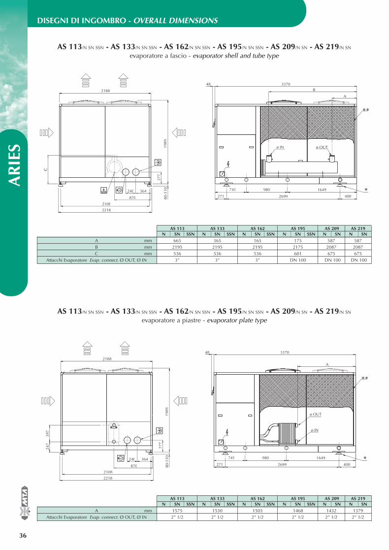
DISEGNI DI INGOMBRO - OVERALL DIMENSIONS A
RIE
S
36
®
240 364
870
2108
2218
80-1
10
C
1989
2188
*4002699271
741 980 1649
**
ø IN ø OUT
B
A
337048
AS 113/N SN SSN - AS 133/N SN SSN - AS 162/N SN SSN - AS 195/N SN SSN - AS 209/N SN - AS 219/N SN
evaporatore a fascio - evaporator shell and tube type
240 364
870
2108
2218
80-1
1019
89
2188
277
247
397
*4002699271
741 980 1649
**
ø IN
ø OUT
A
337048
AS 113/N SN SSN - AS 133/N SN SSN - AS 162/N SN SSN - AS 195/N SN SSN - AS 209/N SN - AS 219/N SN
evaporatore a piastre - evaporator plate type
AS 113 AS 133 AS 162 AS 195 AS 209 AS 219N SN SSN N SN SSN N SN SSN N SN SSN N SN N SN
A mm 665 365 165 175 587 587B mm 2195 2195 2195 2175 2087 2087C mm 536 536 536 601 675 675
Attacchi Evaporatore Evap. connect. Ø OUT, Ø IN 3” 3” 3” DN 100 DN 100 DN 100
AS 113 AS 133 AS 162 AS 195 AS 209 AS 219N SN SSN N SN SSN N SN SSN N SN SSN N SN N SN
A mm 1575 1530 1503 1468 1432 1379Attacchi Evaporatore Evap. connect. Ø OUT, Ø IN 2” 1/2 2” 1/2 2” 1/2 2” 1/2 2” 1/2 2” 1/2
EASYY000BD_V 07-04-2006 12.15 Pagina 36
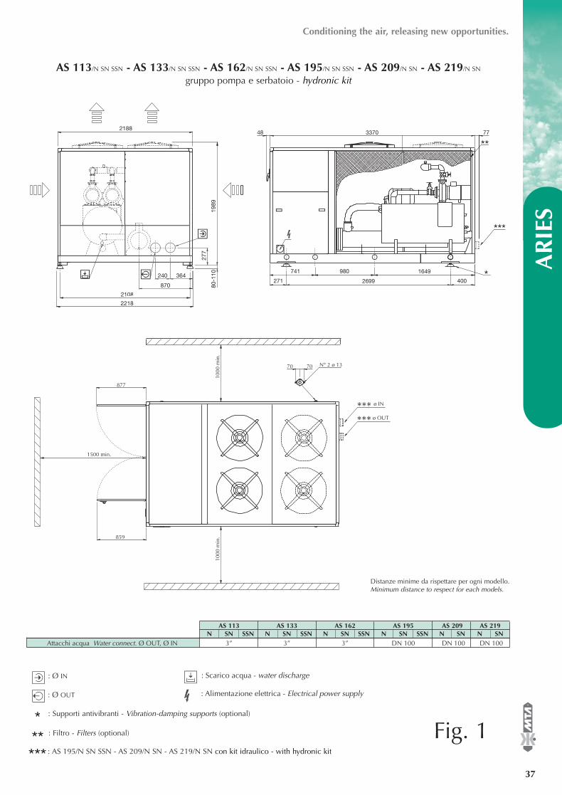
******
: Ø IN
: Ø OUT : Alimentazione elettrica - Electrical power supply
®
AR
IES
37
Conditioning the air, releasing new opportunities.
4002699271
741 980 1649
**337048
240 364
870
2108
2218
80-1
1019
89
2188
*
***
77
AS 113/N SN SSN - AS 133/N SN SSN - AS 162/N SN SSN - AS 195/N SN SSN - AS 209/N SN - AS 219/N SN
gruppo pompa e serbatoio - hydronic kit
ø OUT******
1000
min
.10
00 m
in.
1500 min.
859
877
70 70 N° 2 ø 13
ø IN
: Supporti antivibranti - Vibration-damping supports (optional)
: Scarico acqua - water discharge
: Filtro - Filters (optional)
: AS 195/N SN SSN - AS 209/N SN - AS 219/N SN con kit idraulico - with hydronic kit
Distanze minime da rispettare per ogni modello.Minimum distance to respect for each models.
Fig. 1
AS 113 AS 133 AS 162 AS 195 AS 209 AS 219N SN SSN N SN SSN N SN SSN N SN SSN N SN N SN
Attacchi acqua Water connect. Ø OUT, Ø IN 3” 3” 3” DN 100 DN 100 DN 100
EASYY000BD_V 07-04-2006 12.15 Pagina 37
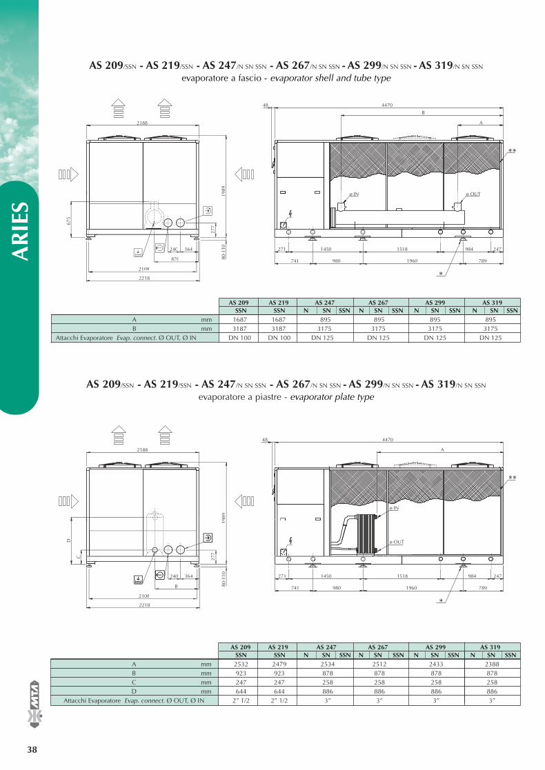
DISEGNI DI INGOMBRO - OVERALL DIMENSIONS A
RIE
S
38
®
2108
2218
240 364
80-1
10
277
1989
2188
675
271
*
**
1450 1518 984 247
7891960741
ø IN ø OUT
A
B
447048
870 980
AS 209/SSN - AS 219/SSN - AS 247/N SN SSN - AS 267/N SN SSN - AS 299/N SN SSN - AS 319/N SN SSN
evaporatore a fascio - evaporator shell and tube type
2108
2218
240 364
80-1
10
277
1989
2188
D
271
*
**
1450 1518 984 247
7891960741
ø IN
ø OUT
A
4470
C
B
48
980
AS 209/SSN - AS 219/SSN - AS 247/N SN SSN - AS 267/N SN SSN - AS 299/N SN SSN - AS 319/N SN SSN
evaporatore a piastre - evaporator plate type
AS 209 AS 219 AS 247 AS 267 AS 299 AS 319SSN SSN N SN SSN N SN SSN N SN SSN N SN SSN
A mm 1687 1687 895 895 895 895B mm 3187 3187 3175 3175 3175 3175
Attacchi Evaporatore Evap. connect. Ø OUT, Ø IN DN 100 DN 100 DN 125 DN 125 DN 125 DN 125
AS 209 AS 219 AS 247 AS 267 AS 299 AS 319SSN SSN N SN SSN N SN SSN N SN SSN N SN SSN
A mm 2532 2479 2534 2512 2433 2388B mm 923 923 878 878 878 878C mm 247 247 258 258 258 258D mm 644 644 886 886 886 886
Attacchi Evaporatore Evap. connect. Ø OUT, Ø IN 2” 1/2 2” 1/2 3” 3” 3” 3”
EASYY000BD_V 07-04-2006 12.15 Pagina 38
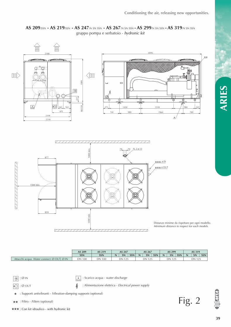
******
: Ø IN
: Ø OUT : Alimentazione elettrica - Electrical power supply
®
AR
IES
39
Conditioning the air, releasing new opportunities.
2108
2218
240 364
80-1
10
277
1989
2188
271
*
**
1450 1518 984 247
7891960741
4595
870 980
AS 209/SSN - AS 219/SSN - AS 247/N SN SSN - AS 267/N SN SSN - AS 299/N SN SSN - AS 319/N SN SSN
gruppo pompa e serbatoio - hydronic kit
877
1500 min.
859
1000
min
.10
00 m
in.
70 70 N. 2 ø 13
ø OUT****** ø IN
: Supporti antivibranti - Vibration-damping supports (optional)
: Scarico acqua - water discharge
: Filtro - Filters (optional)
: Con kit idraulico - with hydronic kit
Distanze minime da rispettare per ogni modello. Minimum distance to respect for each models.
Fig. 2
AS 209 AS 219 AS 247 AS 267 AS 299 AS 319SSN SSN N SN SSN N SN SSN N SN SSN N SN SSN
Attacchi acqua Water connect. Ø OUT, Ø IN DN 100 DN 100 DN 125 DN 125 DN 125 DN 125
EASYY000BD_V 07-04-2006 12.15 Pagina 39
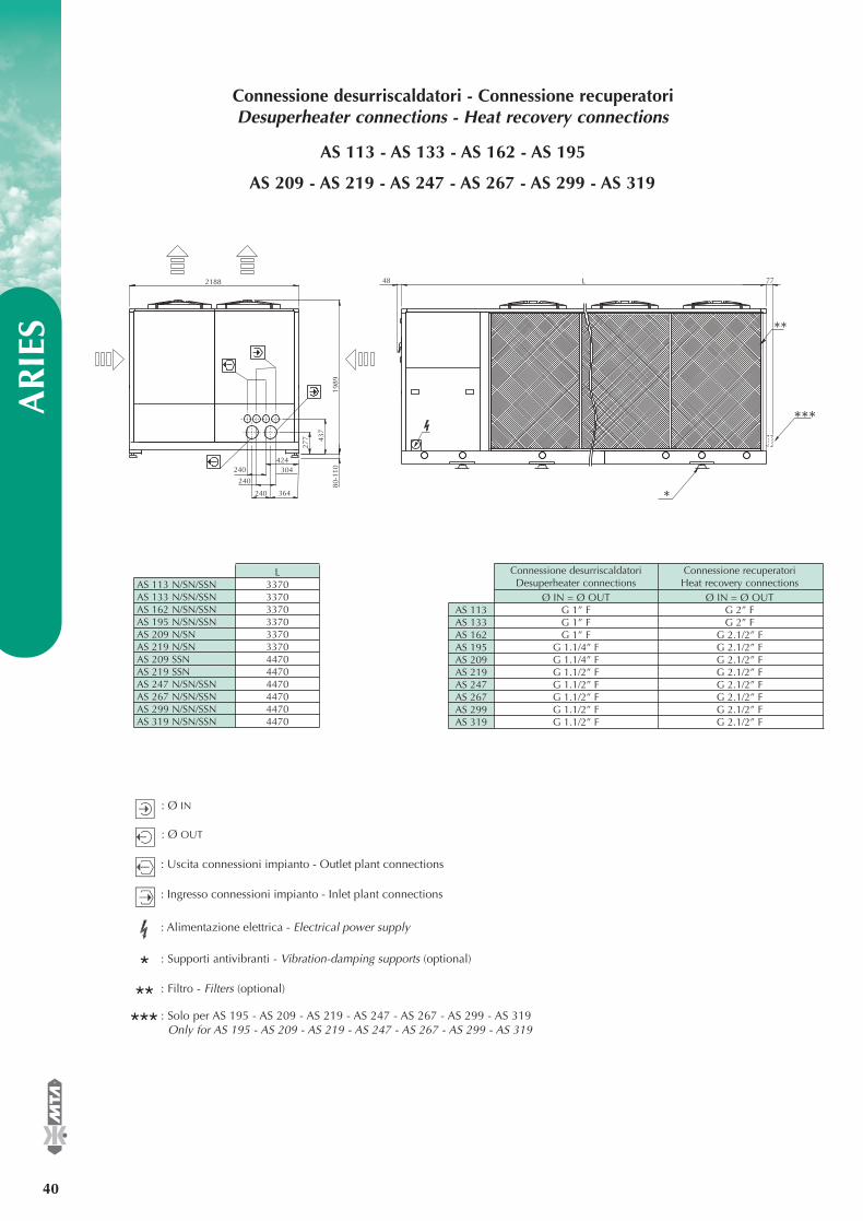
DISEGNI DI INGOMBRO - OVERALL DIMENSIONS A
RIE
S
40
®
Connessione desurriscaldatori - Connessione recuperatoriDesuperheater connections - Heat recovery connections
: Ø IN
: Ø OUT
: Alimentazione elettrica - Electrical power supply
: Supporti antivibranti - Vibration-damping supports (optional)
: Filtro - Filters (optional)
: Ingresso connessioni impianto - Inlet plant connections
Connessione desurriscaldatori Connessione recuperatoriDesuperheater connections Heat recovery connections
Ø IN = Ø OUT Ø IN = Ø OUTAS 113 G 1” F G 2” FAS 133 G 1” F G 2” FAS 162 G 1” F G 2.1/2” FAS 195 G 1.1/4” F G 2.1/2” FAS 209 G 1.1/4” F G 2.1/2” FAS 219 G 1.1/2” F G 2.1/2” FAS 247 G 1.1/2” F G 2.1/2” FAS 267 G 1.1/2” F G 2.1/2” FAS 299 G 1.1/2” F G 2.1/2” FAS 319 G 1.1/2” F G 2.1/2” F
240 364
80-1
10
277
1989
2188
437
424304240
240
*
**
***
48 77L
AS 113 - AS 133 - AS 162 - AS 195
: Uscita connessioni impianto - Outlet plant connections
AS 209 - AS 219 - AS 247 - AS 267 - AS 299 - AS 319
: Solo per AS 195 - AS 209 - AS 219 - AS 247 - AS 267 - AS 299 - AS 319Only for AS 195 - AS 209 - AS 219 - AS 247 - AS 267 - AS 299 - AS 319
******
LAS 113 N/SN/SSN 3370AS 133 N/SN/SSN 3370AS 162 N/SN/SSN 3370AS 195 N/SN/SSN 3370AS 209 N/SN 3370AS 219 N/SN 3370AS 209 SSN 4470AS 219 SSN 4470AS 247 N/SN/SSN 4470AS 267 N/SN/SSN 4470AS 299 N/SN/SSN 4470AS 319 N/SN/SSN 4470
EASYY000BD_V 07-04-2006 12.15 Pagina 40
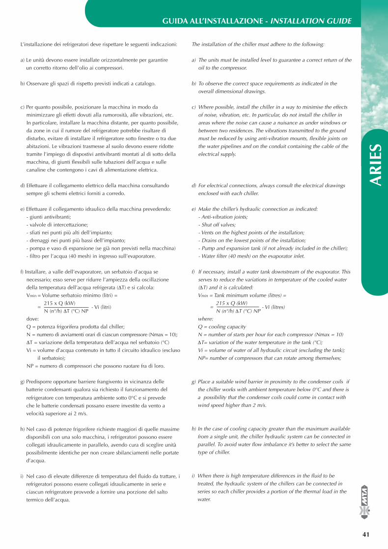
GUIDA ALL’INSTALLAZIONE - INSTALLATION GUIDE
AR
IES
41
®
The installation of the chiller must adhere to the following:
a) The units must be installed level to guarantee a correct return of the
oil to the compressor.
b) To observe the correct space requirements as indicated in the
overall dimensional drawings.
c) Where possible, install the chiller in a way to minimise the effects
of noise, vibration, etc. In particular, do not install the chiller in
areas where the noise can cause a nuisance as under windows or
between two residences. The vibrations transmitted to the ground
must be reduced by using anti-vibration mounts, flexible joints on
the water pipelines and on the conduit containing the cable of the
electrical supply.
d) For electrical connections, always consult the electrical drawings
enclosed with each chiller.
e) Make the chiller’s hydraulic connection as indicated:
- Anti-vibration joints;
- Shut off valves;
- Vents on the highest points of the installation;
- Drains on the lowest points of the installation;
- Pump and expansion tank (if not already included in the chiller);
- Water filter (40 mesh) on the evaporator inlet.
f) If necessary, install a water tank downstream of the evaporator. This
serves to reduce the variations in temperature of the cooled water
(∆T) and it is calculated:
Vmin = Tank minimum volume (litres) =
215 x Q (kW)=
N (n°/h) ∆T (°C) NP - Vi (litres)
where:
Q = cooling capacity
N = number of starts per hour for each compressor (Nmax = 10)
∆T= variation of the water temperature in the tank (°C);
Vi = volume of water of all hydraulic circuit (excluding the tank);
NP= number of compressors that can rotate among themselves;
L’installazione dei refrigeratori deve rispettare le seguenti indicazioni:
a) Le unità devono essere installate orizzontalmente per garantire
un corretto ritorno dell’olio ai compressori.
b) Osservare gli spazi di rispetto previsti indicati a catalogo.
c) Per quanto possibile, posizionare la macchina in modo da
minimizzare gli effetti dovuti alla rumorosità, alle vibrazioni, etc.
In particolare, installare la macchina distante, per quanto possibile,
da zone in cui il rumore del refrigeratore potrebbe risultare di
disturbo, evitare di installare il refrigeratore sotto finestre o tra due
abitazioni. Le vibrazioni trasmesse al suolo devono essere ridotte
tramite l’impiego di dispostivi antivibranti montati al di sotto della
macchina, di giunti flessibili sulle tubazioni dell’acqua e sulle
canaline che contengono i cavi di alimentazione elettrica.
d) Effettuare il collegamento elettrico della macchina consultando
sempre gli schemi elettrici forniti a corredo.
e) Effettuare il collegamento idraulico della macchina prevedendo:
- giunti antivibranti;
- valvole di intercettazione;
- sfiati nei punti più alti dell’impianto;
- drenaggi nei punti più bassi dell’impianto;
- pompa e vaso di espansione (se già non previsti nella macchina)
- filtro per l’acqua (40 mesh) in ingresso sull’evaporatore.
f) Installare, a valle dell’evaporatore, un serbatoio d’acqua se
necessario; esso serve per ridurre l’ampiezza della oscillazione
della temperatura dell’acqua refrigerata (∆T) e si calcola:
Vmin = Volume serbatoio minimo (litri) =
215 x Q (kW)=
N (n°/h) ∆T (°C) NP - Vi (litri)
dove:
Q = potenza frigorifera prodotta dal chiller;
N = numero di avviamenti orari di ciascun compressore (Nmax = 10);
∆T = variazione della temperatura dell’acqua nel serbatoio (°C)
Vi = volume d’acqua contenuto in tutto il circuito idraulico (escluso
il serbatoio);
NP = numero di compressori che possono ruotare fra di loro.
g) Predisporre opportune barriere frangivento in vicinanza delle
batterie condensanti qualora sia richiesto il funzionamento del
refrigeratore con temperatura ambiente sotto 0°C e si prevede
che le batterie condensati possano essere investite da vento a
velocità superiore ai 2 m/s.
h) Nel caso di potenze frigorifere richieste maggiori di quelle massime
disponibili con una solo macchina, i refrigeratori possono essere
collegati idraulicamente in parallelo, avendo cura di sceglire unità
possibilmente identiche per non creare sbilanciamenti nelle portate
d’acqua.
i) Nel caso di elevate differenze di temperatura del fluido da trattare, i
refrigeratori possono essere collegati idraulicamente in serie e
ciascun refrigeratore provvede a fornire una porzione del salto
termico dell’acqua.
g) Place a suitable wind barrier in proximity to the condenser coils if
the chiller works with ambient temperature below 0°C and there is
a possibility that the condenser coils could come in contact with
wind speed higher than 2 m/s.
h) In the case of cooling capacity greater than the maximum available
from a single unit, the chiller hydraulic system can be connected in
parallel. To avoid water flow imbalance it’s better to select the same
type of chiller.
i) When there is high temperature differences in the fluid to be
treated, the hydraulic system of the chillers can be connected in
series so each chiller provides a portion of the thermal load in the
water.
EASYY000BD_V 07-04-2006 12.15 Pagina 41
AR
IES
42
®Conditioning the air, releasing new opportunities.
l) When utilising multiple chillers in parallel, with the condenser coils
face to face, it is necessary to have a minimum distance between
the condenser coils.
m) In the case of water flow greater than the maximum allowed by the
chiller, it is necessary to fit a by-pass between inlet and outlet of
the chiller.
n) In the event of water flow lesser than the minimum allowed by the
chiller, fit a by-pass between outlet and inlet of the chiller.
o) It is recommend to purge all air from the hydraulic system because
a small quantity of air can cause freezing in the evaporator.
p) During inactivity in winter, the hydraulic system must be
discharged or, alternatively, antifreeze must be used. Again we
suggest, specifically for brief unit stops, the use of an antifreezing
heater around evaporator and other antifreezing heaters on the
cooling circuit tubes.
l) Nel caso di utilizzo di più refrigeratori collocati parallelamente
con le batterie condensanti affacciate tra loro è necessario
assicurare una distanza minima tra le batterie condensanti.
m) Nel caso di necessità di trattare portate d’acqua maggiori di quella
massima consentita dal refrigeratore, è conveniente disporre un
by-pass tra ingresso e uscita dal refrigeratore.
n) Nel caso di necessità di trattare portate d’acqua minori di quella
minima consentita dal refrigeratore, è conveniente disporre un
by-pass tra uscita e ingresso dal refrigeratore.
o) Si raccomanda di sfiatare accuratamente l’impianto idraulico in
quanto anche una piccola quantità d’aria può causare il con
gelamento dell’evaporatore.
p) Si raccomanda di scaricare l’impianto idraulico durante le soste
invernali o, in alternativa, di usare miscele anticongelanti. Inoltre
si consiglia, particolarmente nel caso di brevi soste, di richiedere il
refrigeratore con resistenza antigelo sull’evaporatore e di
provvedere ad applicare altre resistenze scaldanti sulle tubazioni
del circuito idraulico.
EASYY000BD_V 07-04-2006 12.15 Pagina 42
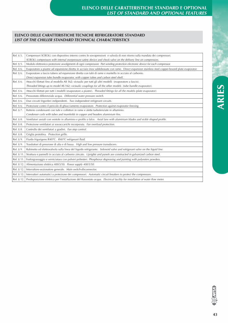
ELENCO DELLE CARATTERISTICHE STANDARD E OPTIONALLIST OF STANDARD AND OPTIONAL FEATURES
AR
IES
43
®
Ref. § 5. Compressori SCROLL con dispositivo interno contro le sovrapressioni e valvola di non ritorno sulla mandata dei compressori.
SCROLL compressors with internal overpressure safety device and check valve on the delivery line on compressors.
Ref. § 5. Modulo elettronico protezione avvolgimenti di ogni compressore Part winding protection electronic device for each compressor.
Ref. § 6. Evaporatore a piastre ad espansione diretta in acciaio inox saldobrasate con rame. Direct expansion stainless steel copper-brazed plate evaporator.
Ref. § 6. Evaporatore a fascio tubero ad espansione diretta con tubi di rame e mantello in acciaio al carbonio.
Direct expansion tube bundle evaporator, with copper tubes and carbon steel shell.
Ref. § 6. Attacchi filettati fino al modello AS 162; victaulic per tutti gli altri modelli (evaporatore a fascio).
Threaded fittings up to model AS 162; victaulic couplings for all the other models (tube bundle evaporator).
Ref. § 6. Attacchi filettati per tutti i modelli (evaporatore a piastre). Threaded fittings for all the models (plate evaporator).
Ref. § 6. Pressostato differenziale acqua. Differential water pressure switch.
Ref. § 6. Due circuiti frigoriferi indipendenti. Two independent refrigerant circuits.
Ref. § 6. Protezione contro il pericolo di ghiacciamento evaporatore. Protection against evaporator freezing.
Ref. § 7. Batterie condensanti con tubi e collettori in rame e alette turbolenziate in alluminio.
Condenser coils with tubes and manifolds in copper and headers aluminium fins.
Ref. § 8. Ventilatori assiali con ventole in alluminio e profilo a falce. Axial fans with aluminium blades and sickle shaped profile.
Ref. § 8. Protezione ventilatori ai sovraccarichi incorporata. Fan overload protection.
Ref. § 8. Controllo dei ventilatori a gradini. Fan step control.
Ref. § 8. Griglia protettiva. Protection grille.
Ref. § 9. Fluido frigorigeno R407C. R407C refrigerant fluid.
Ref. § 9. Trasduttori di pressione di alta e di bassa. High and low pressure transducers.
Ref. § 9. Rubinetto ed elettrovalvola sulla linea del liquido refrigerante. Solenoid valve and refrigerant valve on the liquid line.
Ref. § 11. Struttura e pannelli in acciaio al carbonio zincato. Uprights and panels are constructed in galvanized carbon steel.
Ref. § 11. Fosfosgrassaggio e verniciatura con polveri poliesteri. Phosphorus degreasing and painting with polyesters powders.
Ref. § 12. Alimentazione elettrica 400/3/50. Power supply 400/3/50.
Ref. § 12. Interruttore-sezionatore generale. Main switch-disconnector.
Ref. § 12. Interruttori automatici a protezione dei compressori. Automatic circuit breakers to protect the compressors.
Ref. § 12. Predisposizione elettrica per l'installazione del flussostato acqua. Electrical facility for installation of water flow meter.
ELENCO DELLE CARATTERISTICHE TECNICHE REFRIGERATORE STANDARDLIST OF THE CHILLER STANDARD TECHNICAL CHARACTERISTICS
EASYY000BD_V 07-04-2006 12.15 Pagina 43
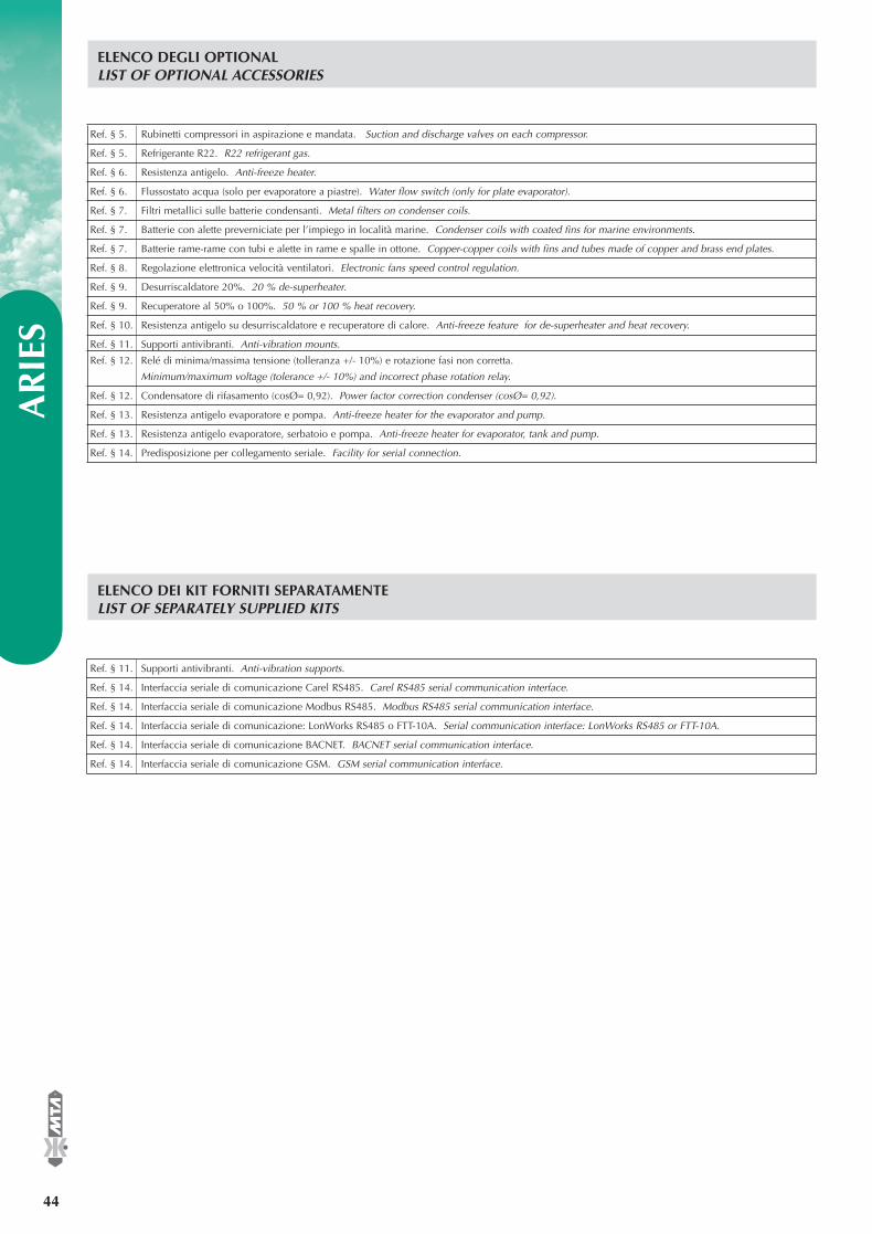
AR
IES
44
®
ELENCO DEGLI OPTIONALLIST OF OPTIONAL ACCESSORIES
Ref. § 5. Rubinetti compressori in aspirazione e mandata. Suction and discharge valves on each compressor.
Ref. § 5. Refrigerante R22. R22 refrigerant gas.
Ref. § 6. Resistenza antigelo. Anti-freeze heater.
Ref. § 6. Flussostato acqua (solo per evaporatore a piastre). Water flow switch (only for plate evaporator).
Ref. § 7. Filtri metallici sulle batterie condensanti. Metal filters on condenser coils.
Ref. § 7. Batterie con alette preverniciate per l’impiego in località marine. Condenser coils with coated fins for marine environments.
Ref. § 7. Batterie rame-rame con tubi e alette in rame e spalle in ottone. Copper-copper coils with fins and tubes made of copper and brass end plates.
Ref. § 8. Regolazione elettronica velocità ventilatori. Electronic fans speed control regulation.
Ref. § 9. Desurriscaldatore 20%. 20 % de-superheater.
Ref. § 9. Recuperatore al 50% o 100%. 50 % or 100 % heat recovery.
Ref. § 10. Resistenza antigelo su desurriscaldatore e recuperatore di calore. Anti-freeze feature for de-superheater and heat recovery.
Ref. § 11. Supporti antivibranti. Anti-vibration mounts.
Ref. § 12. Relé di minima/massima tensione (tolleranza +/- 10%) e rotazione fasi non corretta.
Minimum/maximum voltage (tolerance +/- 10%) and incorrect phase rotation relay.
Ref. § 12. Condensatore di rifasamento (cosØ= 0,92). Power factor correction condenser (cosØ= 0,92).
Ref. § 13. Resistenza antigelo evaporatore e pompa. Anti-freeze heater for the evaporator and pump.
Ref. § 13. Resistenza antigelo evaporatore, serbatoio e pompa. Anti-freeze heater for evaporator, tank and pump.
Ref. § 14. Predisposizione per collegamento seriale. Facility for serial connection.
ELENCO DEI KIT FORNITI SEPARATAMENTELIST OF SEPARATELY SUPPLIED KITS
Ref. § 11. Supporti antivibranti. Anti-vibration supports.
Ref. § 14. Interfaccia seriale di comunicazione Carel RS485. Carel RS485 serial communication interface.
Ref. § 14. Interfaccia seriale di comunicazione Modbus RS485. Modbus RS485 serial communication interface.
Ref. § 14. Interfaccia seriale di comunicazione: LonWorks RS485 o FTT-10A. Serial communication interface: LonWorks RS485 or FTT-10A.
Ref. § 14. Interfaccia seriale di comunicazione BACNET. BACNET serial communication interface.
Ref. § 14. Interfaccia seriale di comunicazione GSM. GSM serial communication interface.
EASYY000BD_V 07-04-2006 12.15 Pagina 44
Conditioning the air, releasing new opportunities.
Refrigeratori d’acqua monoblocco condensati ad ariada 113 a 310 kW con compressori ermetici scroll
Air cooled packaged water chillersfrom 113 to 310 kW with hermetic scroll compressors
R407C - R2250 Hz
ARIES
®
Cooling, drying and caring.Love is in the air
ENVIRONMENTAL
CA R I N G
®
Cooling, drying and caring.
EASY
Y00
0BD
ed. 0
4/20
06 -
Sos
titui
sce
il / R
epla
ce th
e EA
SYY
000B
C
ARIES
DISTRIBUTORE / DISTRIBUTOR
Sede produttiva di ConselveConselve FactoryVia dell’Artigianato, 2 - ZI35026 Conselve (PD) - ItalyTel. +39 049 9597211Fax +39 049 9500620
Uffici RegionaliDomestic Offices
MilanoViale Gavazzi, 5220066 Melzo (MI)Tel. +39 02 95738492Fax +39 02 95738501
PerugiaVia M. Angeloni, 43/CScala F06124 Perugia (PG)Tel./Fax. +39 075 5007718
Uffici CommercialiSales DeptsViale Spagna, 8 - ZI35020 Tribano (PD) - ItalyTel. +39 049 9588611Fax +39 049 9588612 (Dryersales)Fax +39 049 9588661 (Chillersales)Fax +39 049 9588604 (Confortsales)[email protected]
ISO 9001:2000 Certified
Sede produttiva di BagnoliBagnoli FactoryVia Ottava Strada, 4/6 - ZI35023 Bagnoli di Sopra (PD) - ItalyTel. +39 049 9597211Fax +39 049 9500620
Sales Companies
MTA France S.A.ZAC de Chassagne69360 TERNAY - FTel. +33 04 7249 8989Fax +33 04 7249 8980www.mtafrance.fr
MTA Deutschland GmbHWeihersfeld 46D 41379 BrüggenTel. +49 2163 5796-0Fax. +49 2163 5796-66www.mta.de
MTA Australasia PTY.LTD13 - 15 Apollo DriveHALLAM VIC. 3803 - AUSTel. +61 3 9702 4348Fax. +61 3 9702 4948www.mta-au.com
Novair-MTA, S.A.Ronda Shimizu, 6Pol. Ind. Can TorrellaE-08233 VacarissesBarcelona (SPAIN)Tel. +34 938 281 790Fax. +34 938 359 581www.novair.es
MTA USA LLC180 Wales Ave. Suite 180Tonawanda, New York 14150Tel. 716 693 8651Fax. 716 693 8654
La MTA nell’ ottica di un miglioramento continuo del prodotto, si riserva il diritto di cambiare i dati presenti in questo catalogo senzaobbligo di preavviso. Per ulteriori informazioni rivolgersi agli uffici commerciali. La riproduzione, anche parziale, é vietata.
The data in this technical booklet are not binding. With a view to continuous product improvement, MTA reserves the right to makechanges without prior notice. For further information, request to Sale Offices. Reproduction in whole or in part is forbidden.
MTA (Shanghai) Co., LtdRoom 1409, Yinyuan MansionN. 6555 Humin Road201100 ShanghaiP.R. of ChinaTel. +86 21 54171080Fax. +86 21 54171081www.mta-it.com.cn
NapoliVia E. Forzati, 27Is. B Scala B80146 NapoliTel./Fax. +39 081 2551440