Embed Size (px)
Citation preview
PUBLISHED BY THE AMERICAN WELDING SOCIETY TO ADVANCE THE SCIENCE, TECHNOLOGY, AND APPLICATION OF WELDINGAND ALLIED JOINING AND CUTTING PROCESSES, INCLUDING BRAZING, SOLDERING, AND THERMAL SPRAYING
February 2011
Shipbuilding
Weld Repairs
The American
Welder
r17706_Layout 1 3/2/11 3:49 PM Page 1
TECHNOLOGY
In a recent cooperative experiment between Canadian andAustralian companies, engineers ran two tests of precision plateweld preparation attaching a new three-axis (ACZ) plasma bevelhead to a conventional XY plate profiler to create a synchronousfive-axis plasma profiler. The core question was whether the new-generation plasma torches combined with the latest many axiscontrols were capable of producing multi-face beveled edges ofsufficient accuracy for practical weld preparation.
Numerically controlled (NC) plate beveling machines havebeen in the marketplace for 30 years. However, their populationis less than 0.5% of the approximately 200,000 machines world-wide. Therefore, plate weld preparation remains as it has alwaysbeen, a shop problem, and almost all plate steel is square cut ex-cept for shipbuilding and, lately, for windtowers. So despite mas-sive advances in welding technology over the years, the requiredweld preparation is still a semi-manual process: slow, dirty, de-manding, costly, and requiring skilled operators. With an agingworkforce, this is a serious problem for maintaining core capaci-ties in heavy engineering.
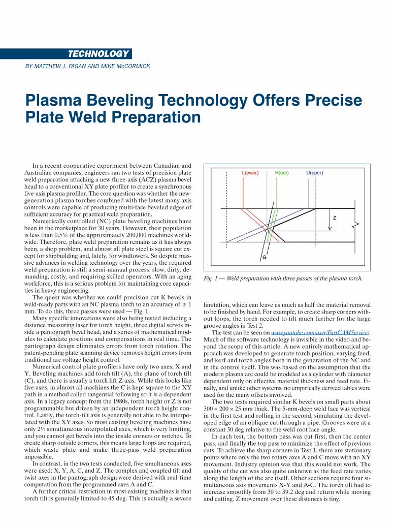
The quest was whether we could precision cut K bevels inweld-ready parts with an NC plasma torch to an accuracy of ± 1mm. To do this, three passes were used — Fig. 1.
Many specific innovations were also being tested including adistance measuring laser for torch height, three digital servos in-side a pantograph bevel head, and a series of mathematical mod-ules to calculate positions and compensations in real time. Thepantograph design eliminates errors from torch rotation. Thepatent-pending plate scanning device removes height errors fromtraditional arc voltage height control.
Numerical control plate profilers have only two axes, X andY. Beveling machines add torch tilt (A), the plane of torch tilt(C), and there is usually a torch lift Z axis. While this looks likefive axes, in almost all machines the C is kept square to the XYpath in a method called tangential following so it is a dependentaxis. In a legacy concept from the 1980s, torch height or Z is notprogrammable but driven by an independent torch height con-trol. Lastly, the torch-tilt axis is generally not able to be interpo-lated with the XY axes. So most existing beveling machines haveonly 2½ simultaneous interpolated axes, which is very limiting,and you cannot get bevels into the inside corners or notches. Tocreate sharp outside corners, this means large loops are required,which waste plate and make three-pass weld preparation impossible.
In contrast, in the two tests conducted, five simultaneous axeswere used: X, Y, A, C, and Z. The complex and coupled tilt andtwist axes in the pantograph design were derived with real-timecomputation from the programmed axes A and C.
A further critical restriction in most existing machines is thattorch tilt is generally limited to 45 deg. This is actually a severe
limitation, which can leave as much as half the material removalto be finished by hand. For example, to create sharp corners with-out loops, the torch needed to tilt much further for the largegroove angles in Test 2.
The test can be seen on www.youtube.com/user/FastCAMService/.Much of the software technology is invisible in the video and be-yond the scope of this article. A new entirely mathematical ap-proach was developed to generate torch position, varying feed,and kerf and torch angles both in the generation of the NC andin the control itself. This was based on the assumption that themodern plasma arc could be modeled as a cylinder with diameterdependent only on effective material thickness and feed rate. Fi-nally, and unlike other systems, no empirically derived tables wereused for the many offsets involved.
The two tests required similar K bevels on small parts about300 × 200 × 25 mm thick. The 5-mm-deep weld face was verticalin the first test and rolling in the second, simulating the devel-oped edge of an oblique cut through a pipe. Grooves were at aconstant 30 deg relative to the weld root face angle.
In each test, the bottom pass was cut first, then the centerpass, and finally the top pass to minimize the effect of previouscuts. To achieve the sharp corners in Test 1, there are stationarypoints where only the two rotary axes A and C move with no XYmovement. Industry opinion was that this would not work. Thequality of the cut was also quite unknown as the feed rate variesalong the length of the arc itself. Other sections require four si-multaneous axis movements X-Y and A-C. The torch tilt had toincrease smoothly from 30 to 39.2 deg and return while movingand cutting. Z movement over these distances is tiny.
BY MATTHEW J. FAGAN AND MIKE McCORMICK
Plasma Beveling Technology Offers PrecisePlate Weld Preparation
Fig. 1 — Weld preparation with three passes of the plasma torch.
r17706_Layout 1 3/2/11 3:49 PM Page 94
In the earliesttests, it was unknownwhether the V-shaped scrap betweenthe first and secondpasses would dropand block the thirdpass, the part movebetween passes, thecorners melt away,and the arc stay cut-ting when the ma-chine was not actuallymoving. Even suc-cessful crossing of ex-isting cut paths wasunknown let alonepart tolerances andquality. Dross was a
concern as was the path of the plasma beam when additionalpathways were available for the plasma stream. Splitting and cur-vature of the beam were possibilities.
Close examination of the finished parts indicated very accept-able quality, straight cuts, and size and edge profiles within tol-erances at cuts up to 55 deg.
The Bevel Editor. Not shown in the videos is that the three-passNC programs were created from the CAM file without explicit NCprogramming. In the patent-pending concept, 3D CAM parts arecompletely defined by a welding professional including all weldpreparation.
The CAM files remain 2-D in nature with parameterizationon each geometric entity to enable the recreation of the 3-D part.The files at this point are independent of the cutting process.
To create these files, a separate piece of software called BevelEditor is needed. It is the intention of FastCAM, Inc., to makeBevel Editor free to welding professionals.
At the production site, the files are nested onto a plate for aspecific machine and cutting technology. It is only then that partgeometry is translated into multiple passes on the top of the plate.The machine-specific NC code is generated automatically withall the compensations, offsets, passes, and corners in place. Withthis approach, there is also no practical difference between nest-ing and cutting weld-ready parts and traditional square cut partsallowing a smooth transition to the new technologies.
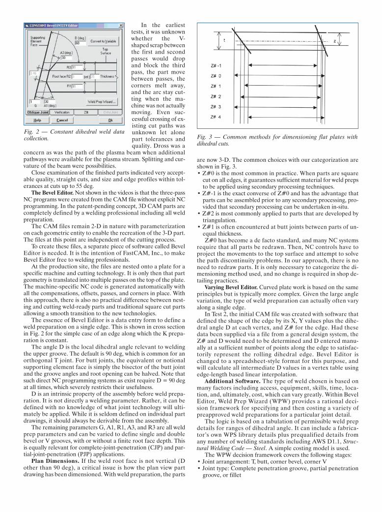
The essence of Bevel Editor is a data entry form to define aweld preparation on a single edge. This is shown in cross sectionin Fig. 2 for the simple case of an edge along which the K prepa-ration is constant.
The angle D is the local dihedral angle relevant to weldingthe upper groove. The default is 90 deg, which is common for anorthogonal T joint. For butt joints, the equivalent or notionalsupporting element face is simply the bisector of the butt jointand the groove angles and root opening can be halved. Note thatsuch direct NC programming systems as exist require D = 90 degat all times, which severely restricts their usefulness.
D is an intrinsic property of the assembly before weld prepa-ration. It is not directly a welding parameter. Rather, it can bedefined with no knowledge of what joint technology will ulti-mately be applied. While it is seldom defined on individual partdrawings, it should always be derivable from the assembly.
The remaining parameters G, A1, R1, A3, and R3 are all weldprep parameters and can be varied to define single and doublebevel or V grooves, with or without a finite root face depth. Thisis equally relevant for complete-joint-penetration (CJP) and par-tial-joint-penetration (PJP) applications.
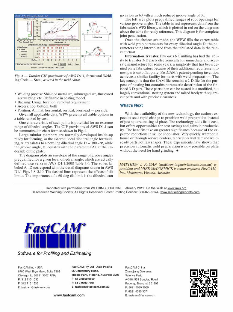
Plan Dimensions. If the weld root face is not vertical (Dother than 90 deg), a critical issue is how the plan view partdrawing has been dimensioned. With weld preparation, the parts
are now 3-D. The common choices with our categorization areshown in Fig. 3. • Z#0 is the most common in practice. When parts are square
cut on all edges, it guarantees sufficient material for weld prepsto be applied using secondary processing techniques.
• Z#-1 is the exact converse of Z#0 and has the advantage thatparts can be assembled prior to any secondary processing, pro-vided that secondary processing can be undertaken in-situ.
• Z#2 is most commonly applied to parts that are developed bytriangulation.
• Z#1 is often encountered at butt joints between parts of un-equal thickness. Z#0 has become a de facto standard, and many NC systems
require that all parts be redrawn. Then, NC controls have toproject the movements to the top surface and attempt to solvethe path discontinuity problems. In our approach, there is noneed to redraw parts. It is only necessary to categorize the di-mensioning method used, and no change is required in shop de-tailing practices.
Varying Bevel Editor. Curved plate work is based on the sameprinciples but is typically more complex. Given the large anglevariation, the type of weld preparation can actually often varyalong a single edge.
In Test 2, the initial CAM file was created with software thatdefined the shape of the edge by its X, Y values plus the dihe-dral angle D at each vertex, and Z# for the edge. Had thesedata been supplied via a file from a general design system, theZ# and D would need to be determined and D entered manu-ally at a sufficient number of points along the edge to satisfac-torily represent the rolling dihedral edge. Bevel Editor ischanged to a spreadsheet-style format for this purpose, andwill calculate all intermediate D values in a vertex table usingedge-length based linear interpolation.
Additional Software. The type of weld chosen is based onmany factors including access, equipment, skills, time, loca-tion, and, ultimately, cost, which can vary greatly. Within BevelEditor, Weld Prep Wizard (WPW) provides a rational deci-sion framework for specifying and then costing a variety ofpreapproved weld preparations for a particular joint detail.
The logic is based on a tabulation of permissible weld prepdetails for ranges of dihedral angle. It can include a fabrica-tor’s own WPS library details plus prequalified details fromany number of welding standards including AWS D1.1, Struc-tural Welding Code — Steel. A simple costing model is used.
The WPW decision framework covers the following stages: • Joint arrangement: T, butt, corner bevel, corner V• Joint type: Complete penetration groove, partial penetration
groove, or fillet
Fig. 2 — Constant dihedral weld data collection. Fig. 3 — Common methods for dimensioning flat plates with
dihedral cuts.
r17706_Layout 1 3/2/11 3:49 PM Page 95
• Welding process: Shielded metal arc, submerged arc, flux coredarc welding, etc. (definable in costing model)
• Backing: Usage, location, removal requirement• Access: Top, bottom, both• Position: All, flat, horizontal, vertical, overhead — per side.
Given all applicable data, WPW presents all viable options ina table ranked by cost.
One characteristic of such joints is potential for an extremerange of dihedral angles. The CJP provisions of AWS D1.1 canbe summarized in chart form as shown in Fig. 4.
Large tubular members are normally developed inside-upready for forming, so the external local dihedral angle for weld-ing, Ψ, translates to a beveling dihedral angle D = 180 – Ψ, whilethe groove angle, Φ, equates with the parameter A1 at the un-derside of the plate.
The diagram plots an envelope of the range of groove anglesprequalified for a given local dihedral angle, which are actuallydefined vice versa in AWS D1.1:2008 Table 3.6. The zones la-beled A...D correspond with the detail diagrams drawn in AWSD1.1 Figs. 3.8–3.10. The dashed lines represent the effects of tiltlimits. The importance of a 60-deg tilt limit is the dihedral can
go as low as 60 with a much reduced groove angle of 30.The left area plots prequalified ranges of root openings for
various groove angles. The table in red represents data from thefabricator’s WPS library, which is plotted in red on the diagramsabove the table for ready reference. This diagram is for completejoint penetration.
Once the choices are made, the WPW fills the vertex tablewith weld prep parameters for every dihedral angle D, the pa-rameters being interpolated from the tabulated data in the rele-vant chart.
Information Transfer. Five-axis NC milling has had the abil-ity to transfer 3-D parts electronically for immediate and accu-rate manufacture for some years, a simplicity that has been de-nied plate fabricators because of their additional requirement tonest parts onto flat plate. FastCAM’s patent-pending inventionachieves a similar facility for parts with weld preparation. Thekey concept is that the CAM file remains a 2-D file for the pur-pose of nesting but contains parametric description of the fin-ished 3-D part. These parts then can be nested in a modified, butlargely conventional, nesting system and mixed freely with square-cut parts and with precise clearances.
Whatʼs Next
With the availability of the new technology, the authors ex-pect to see a rapid change to precision weld preparation insteadof just square cutting of plate. The technology adds little cost,but offers opportunities for cost savings and gains in productiv-ity. The benefits take on greater significance because of the ex-pected reductions in skilled shop labor. Very quickly, whether inhouse or through service centers, fabricators will demand weld-ready parts not raw shapes. These experiments have shown thatprecision automatic weld preparation is now possible on platewithout the need for hand grinding.
Fig. 4 — Tabular CJP provisions of AWS D1.1, Structural Weld-ing Code — Steel, as used in the weld editor.
MATTHEW J. FAGAN ([email protected]) is president and MIKE McCORMICK is senior engineer, FastCAM,Inc., Melbourne, Victoria, Australia.
Reprinted with permission from WELDING JOURNAL, February 2011. On the Web at www.aws.org.© American Welding Society. All Rights Reserved. Foster Printing Service: 866-879-9144, www.marketingreprints.com.
Software for Profiling and Estimating
FastCAM Inc - USA8700 West Bryn Mawr, Suite 730S Chicago, IL, 60631 3507, USA P: 312 715 1535 F: 312 715 1536E: [email protected]
FastCAM Pty Ltd - Asia Pacific96 Canterbury Road, Middle Park, Victoria, Australia 3206 P: 61 3 9699 9899 F: 61 3 9699 7501E: [email protected]
FastCAM China Zhangjiang Overseas Science Park A-318, 563 Songtao Road Pudong, Shanghai 201203 P: 8621 5080 3069 F: 8621 5080 3071E: [email protected] www.fastcam.com
r17706_Layout 1 3/2/11 3:49 PM Page 96