Embed Size (px)
Citation preview
BOAR-SystronicType series booklet7540.1/7--10
Energy--saving system for supplytemperature control in room heating
and air--conditioning systems(replaces 3-way valve)
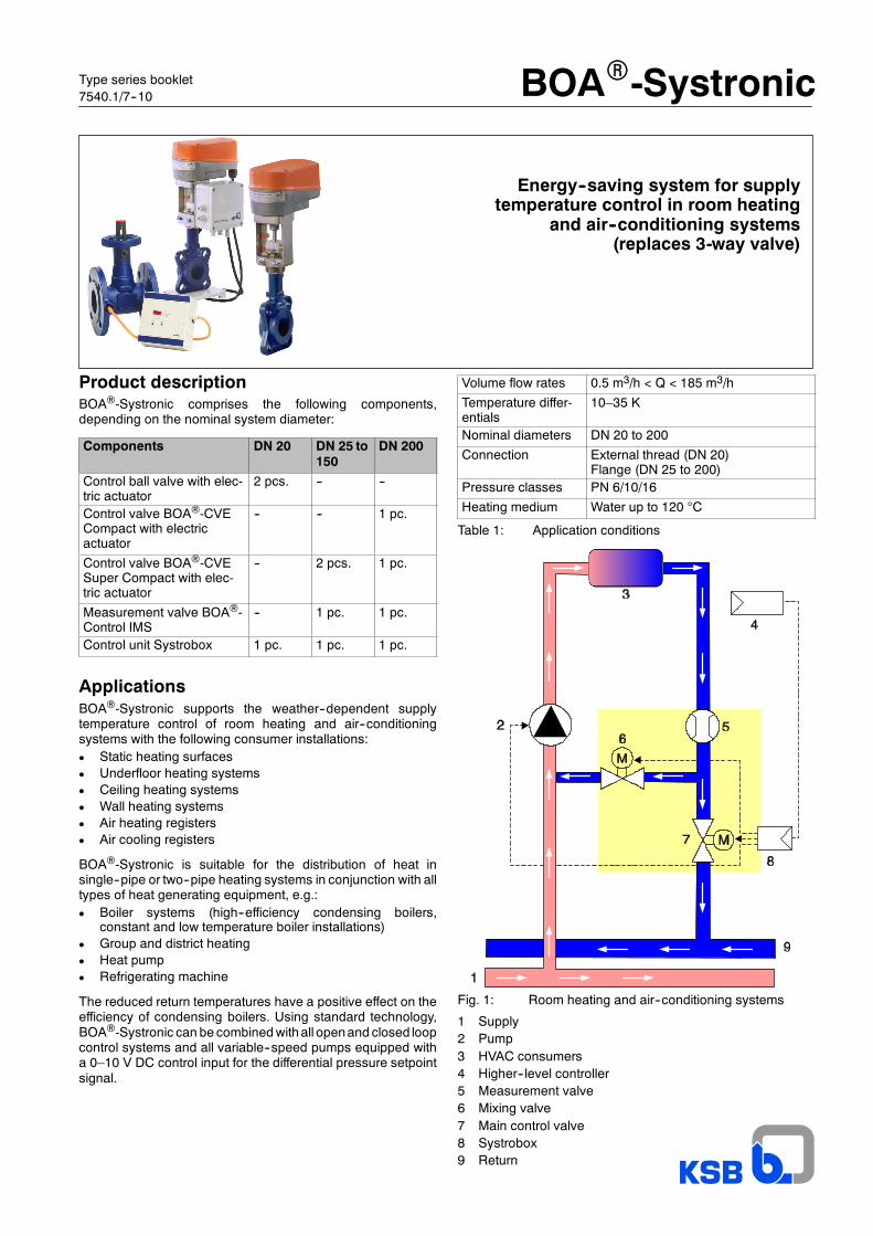
Product descriptionBOA®-Systronic comprises the following components,depending on the nominal system diameter:
Components DN 20 DN 25 to150
DN 200
Control ball valve with elec-tric actuator
2 pcs. -- --
Control valve BOA®-CVECompact with electricactuator
-- -- 1 pc.
Control valve BOA®-CVESuper Compact with elec-tric actuator
-- 2 pcs. 1 pc.
Measurement valve BOA®-Control IMS
-- 1 pc. 1 pc.
Control unit Systrobox 1 pc. 1 pc. 1 pc.
ApplicationsBOA®-Systronic supports the weather--dependent supplytemperature control of room heating and air--conditioningsystems with the following consumer installations:D Static heating surfacesD Underfloor heating systemsD Ceiling heating systemsD Wall heating systemsD Air heating registersD Air cooling registers
BOA®-Systronic is suitable for the distribution of heat insingle--pipe or two--pipe heating systems in conjunction with alltypes of heat generating equipment, e.g.:D Boiler systems (high--efficiency condensing boilers,
constant and low temperature boiler installations)D Group and district heatingD Heat pumpD Refrigerating machine
The reduced return temperatures have a positive effect on theefficiency of condensing boilers. Using standard technology,BOA®-Systronic can be combinedwithall openand closed loopcontrol systems and all variable--speed pumps equipped witha 0–10 V DC control input for the differential pressure setpointsignal.
Volume flow rates 0.5 m3/h < Q < 185 m3/h
Temperature differ-entials
10–35 K
Nominal diameters DN 20 to 200
Connection External thread (DN 20)Flange (DN 25 to 200)
Pressure classes PN 6/10/16
Heating medium Water up to 120 °C
Table 1: Application conditions
Fig. 1: Room heating and air--conditioning systems
1 Supply2 Pump3 HVAC consumers4 Higher--level controller5 Measurement valve6 Mixing valve7 Main control valve8 Systrobox9 Return
BOAR-Systronic
2
Applications
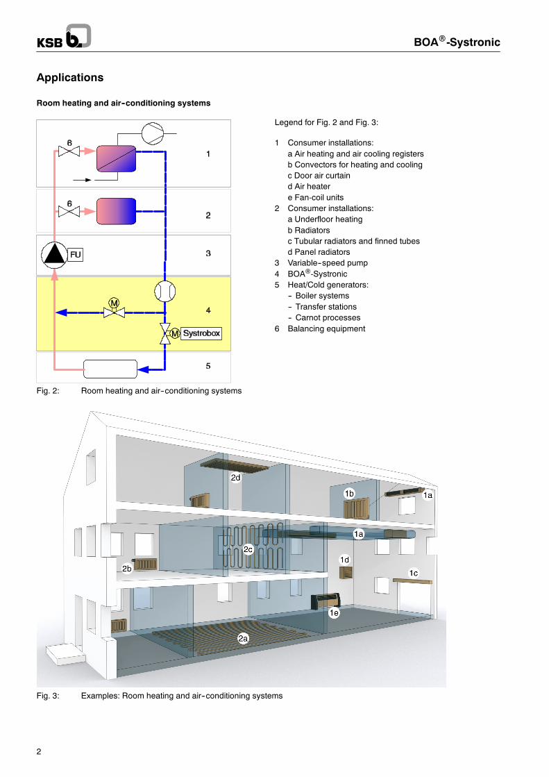
Room heating and air--conditioning systems
Fig. 2: Room heating and air--conditioning systems
Legend for Fig. 2 and Fig. 3:
1 Consumer installations:a Air heating and air cooling registersb Convectors for heating and coolingc Door air curtaind Air heatere Fan-coil units
2 Consumer installations:a Underfloor heatingb Radiatorsc Tubular radiators and finned tubesd Panel radiators
3 Variable--speed pump4 BOA®-Systronic5 Heat/Cold generators:
-- Boiler systems-- Transfer stations-- Carnot processes
6 Balancing equipment
Fig. 3: Examples: Room heating and air--conditioning systems
Example
BOAR-Systronic
3
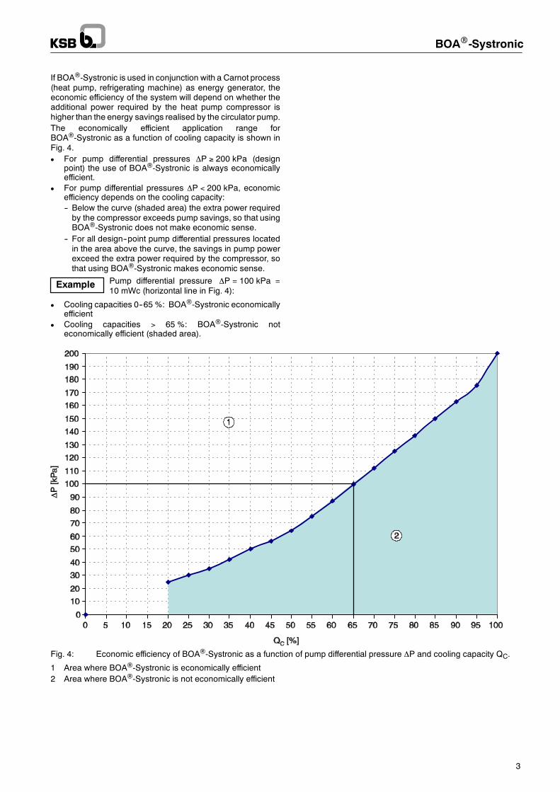
If BOA®-Systronic is used in conjunction with a Carnot process(heat pump, refrigerating machine) as energy generator, theeconomic efficiency of the system will depend on whether theadditional power required by the heat pump compressor ishigher than the energy savings realised by the circulator pump.The economically efficient application range forBOA®-Systronic as a function of cooling capacity is shown inFig. 4.D For pump differential pressures ∆P ≥ 200 kPa (design
point) the use of BOA®-Systronic is always economicallyefficient.
D For pump differential pressures ∆P < 200 kPa, economicefficiency depends on the cooling capacity:-- Below the curve (shaded area) the extra power requiredby the compressor exceeds pump savings, so that usingBOA®-Systronic does not make economic sense.
-- For all design--point pump differential pressures locatedin the area above the curve, the savings in pump powerexceed the extra power required by the compressor, sothat using BOA®-Systronic makes economic sense.
Pump differential pressure ∆P = 100 kPa =10 mWc (horizontal line in Fig. 4):
D Cooling capacities 0--65 %: BOA®-Systronic economicallyefficient
D Cooling capacities > 65 %: BOA®-Systronic noteconomically efficient (shaded area).
Fig. 4: Economic efficiency of BOA®-Systronic as a function of pump differential pressure ∆P and cooling capacity QC.
1 Area where BOA®-Systronic is economically efficient2 Area where BOA®-Systronic is not economically efficient
Note
BOAR-Systronic
4
BenefitsBOA®-Systronic has the following main characteristics:
Characteristics Benefits
Drastically reduced energyconsumption of the pump
70 % lower operating costs
Quadrupled efficiency Future--oriented technology
Well--proven standard tech-nology
Reliability
No flow noises Added user comfort
Simple system selection Reduced planning costs
Automatic adjustment of vo-lume flow rates in main sup-ply/return section of heatingcircuit
Reduced commissioningcosts
Table 2: Special characteristics and benefits ofBOA®-Systronic
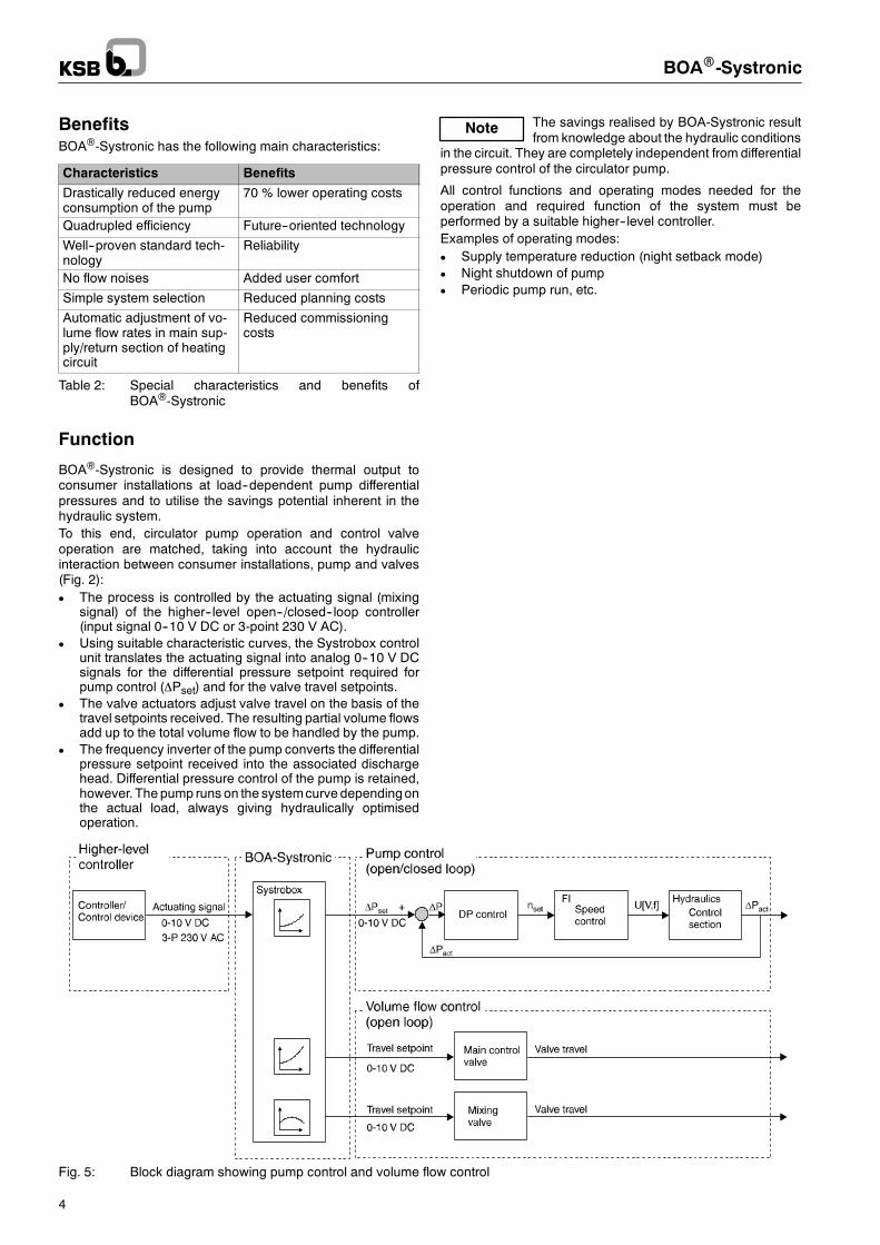
Function
BOA®-Systronic is designed to provide thermal output toconsumer installations at load--dependent pump differentialpressures and to utilise the savings potential inherent in thehydraulic system.To this end, circulator pump operation and control valveoperation are matched, taking into account the hydraulicinteraction between consumer installations, pump and valves(Fig. 2):D The process is controlled by the actuating signal (mixing
signal) of the higher--level open--/closed--loop controller(input signal 0--10 V DC or 3-point 230 V AC).
D Using suitable characteristic curves, the Systrobox controlunit translates the actuating signal into analog 0--10 V DCsignals for the differential pressure setpoint required forpump control (∆Pset) and for the valve travel setpoints.
D The valve actuators adjust valve travel on the basis of thetravel setpoints received. The resulting partial volume flowsadd up to the total volume flow to be handled by the pump.
D The frequency inverter of the pump converts the differentialpressure setpoint received into the associated dischargehead. Differential pressure control of the pump is retained,however. The pump runs on the systemcurve dependingonthe actual load, always giving hydraulically optimisedoperation.
The savings realised by BOA-Systronic resultfrom knowledge about the hydraulic conditions
in the circuit. They are completely independent from differentialpressure control of the circulator pump.
All control functions and operating modes needed for theoperation and required function of the system must beperformed by a suitable higher--level controller.Examples of operating modes:D Supply temperature reduction (night setback mode)D Night shutdown of pumpD Periodic pump run, etc.
Fig. 5: Block diagram showing pump control and volume flow control
BOAR-Systronic
5
Volume flow rates and discharge heads
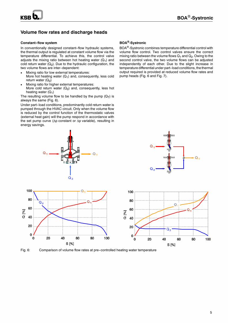
Constant--flow system
In conventionally designed constant--flow hydraulic systems,the thermal output is regulated at constant volume flow via thetemperature differential. To achieve this, the control valveadjusts the mixing ratio between hot heating water (Q1) andcold return water (Q2). Due to the hydraulic configuration, thetwo volume flows are inter--dependent:D Mixing ratio for low external temperatures:
More hot heating water (Q1) and, consequently, less coldreturn water (Q2)
D Mixing ratio for higher external temperatures:More cold return water (Q2) and, consequently, less hotheating water (Q1)
The resulting volume flow to be handled by the pump (QT) isalways the same (Fig. 6).Under part--load conditions, predominantly cold return water ispumped through the HVAC circuit. Only when the volume flowis reduced by the control function of the thermostatic valves(external heat gain) will the pump respond in accordance withthe set pump curve (∆p constant or ∆p variable), resulting inenergy savings.
BOA®-Systronic
BOA®-Systronic combines temperature differential control withvolume flow control. Two control valves ensure the correctmixing ratio between the volume flows Q1 and Q2. Owing to thesecond control valve, the two volume flows can be adjustedindependently of each other. Due to the slight increase intemperature differential under part--load conditions, the thermaloutput required is provided at reduced volume flow rates andpump heads (Fig. 6 and Fig. 7).
Fig. 6: Comparison of volume flow rates at pre--controlled heating water temperature
BOAR-Systronic
6
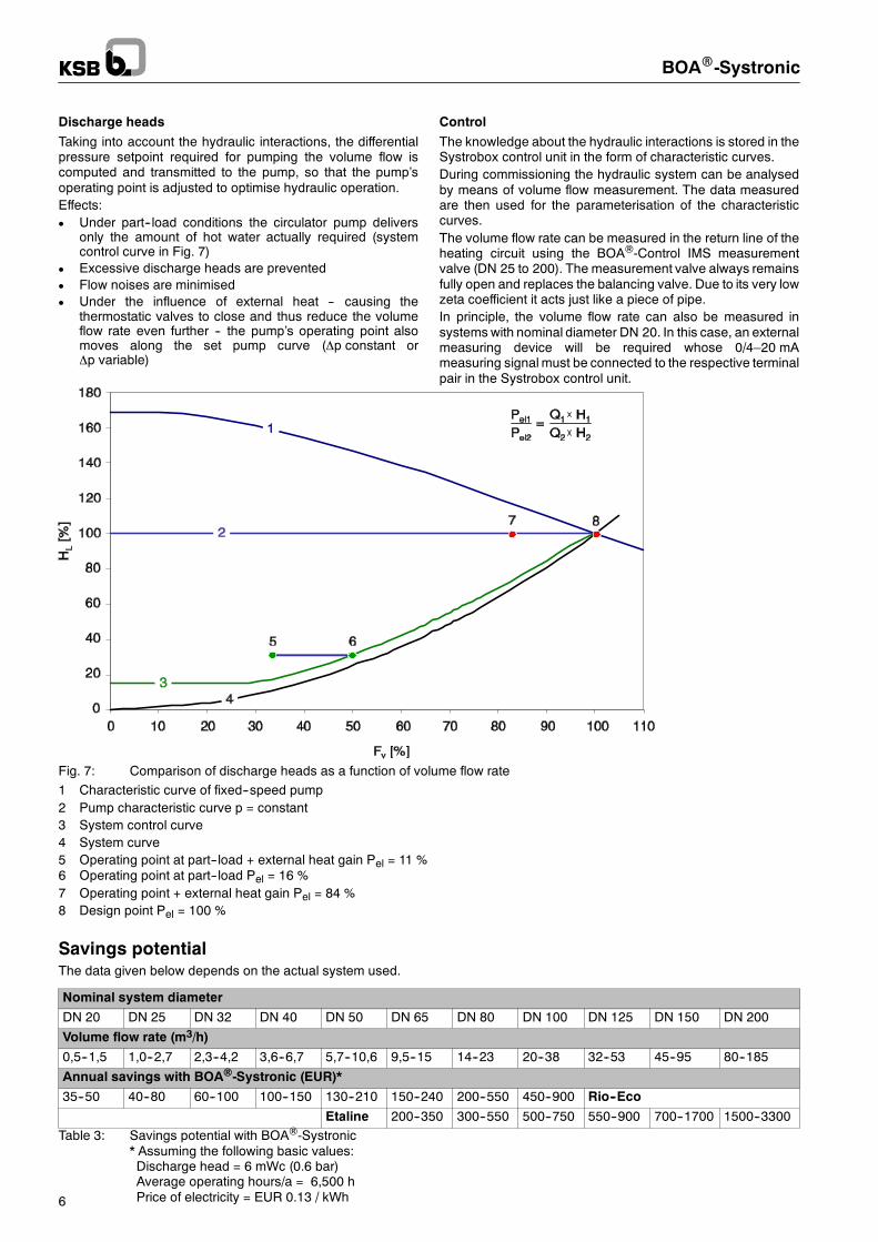
Discharge heads
Taking into account the hydraulic interactions, the differentialpressure setpoint required for pumping the volume flow iscomputed and transmitted to the pump, so that the pump’soperating point is adjusted to optimise hydraulic operation.Effects:D Under part--load conditions the circulator pump delivers
only the amount of hot water actually required (systemcontrol curve in Fig. 7)
D Excessive discharge heads are preventedD Flow noises are minimisedD Under the influence of external heat -- causing the
thermostatic valves to close and thus reduce the volumeflow rate even further -- the pump’s operating point alsomoves along the set pump curve (∆p constant or∆p variable)
Control
The knowledge about the hydraulic interactions is stored in theSystrobox control unit in the form of characteristic curves.During commissioning the hydraulic system can be analysedby means of volume flow measurement. The data measuredare then used for the parameterisation of the characteristiccurves.The volume flow rate can be measured in the return line of theheating circuit using the BOA®-Control IMS measurementvalve (DN 25 to 200). The measurement valve always remainsfully open and replaces the balancing valve. Due to its very lowzeta coefficient it acts just like a piece of pipe.In principle, the volume flow rate can also be measured insystems with nominal diameter DN 20. In this case, an externalmeasuring device will be required whose 0/4–20 mAmeasuring signal must be connected to the respective terminalpair in the Systrobox control unit.
Fig. 7: Comparison of discharge heads as a function of volume flow rate1 Characteristic curve of fixed--speed pump2 Pump characteristic curve p = constant3 System control curve4 System curve5 Operating point at part--load + external heat gain Pel = 11 %6 Operating point at part--load Pel = 16 %7 Operating point + external heat gain Pel = 84 %8 Design point Pel = 100 %
Savings potentialThe data given below depends on the actual system used.
Nominal system diameter
DN 20 DN 25 DN 32 DN 40 DN 50 DN 65 DN 80 DN 100 DN 125 DN 150 DN 200
Volume flow rate (m3/h)
0,5--1,5 1,0--2,7 2,3--4,2 3,6--6,7 5,7--10,6 9,5--15 14--23 20--38 32--53 45--95 80--185
Annual savings with BOA®-Systronic (EUR)*
35--50 40--80 60--100 100--150 130--210 150--240 200--550 450--900 Rio--Eco
Etaline 200--350 300--550 500--750 550--900 700--1700 1500--3300Table 3: Savings potential with BOA®-Systronic
* Assuming the following basic values:Discharge head = 6 mWc (0.6 bar)Average operating hours/a = 6,500 hPrice of electricity = EUR 0.13 / kWh
Note
Note
BOAR-Systronic
7
Scope of supply and installation
Qty. Description
Nominal system diameter DN 20
1 Control ball valve DN 20 with-- electric rotary actuator for adjusting the mixing
ratio-- mounted and operational Systrobox control unitInstalled in: Supply or return line of heating circuit
1 Control ball valve DN 15 with electric rotary actua-tor for adjusting the mixing ratioInstalled in: Mixing line
Nominal system diameter DN 25 to 200
1 Control valve BOA®-CVE SuperCompact(BOA®-CVE Compact for DN 200) with-- electric actuator for adjusting the mixing ratio-- mounted and operational Systrobox control unitInstalled in: Supply or return line of heating circuit
1 Control valve BOA®-CVE SuperCompact withelectric actuator for adjusting the mixing ratioInstalled in: Mixing line
1 Measurement valve BOA®-Control IMS for measu-ring the volume flow rate during commissioningInstalled in: Return line of heating circuit
Table 4: Scope of supply and installationThe pump is not included in the scope ofsupply.
USB-Nano-485 interface converter and connection cable
For uploading the system configuration from a laptop computer/ PC to the Systrobox control unit. The converter must beconnected to a free USB port of the laptop / PC.
Accessories Ident. number
USB-Nano-485 interface converter 48 014 071
Connection cable 48 014 070
Parameterisation kitComprises USB-Nano-485 interface converter, connectioncable and commissioning tool on CD--ROM.
Accessories Ident. number
Parameterisation kit 48 014 073
Flow meterFor volume flow measurement with BOA®-Control IMS (DN 25to 200), to optimally adjust the control curves to the hydraulicconditions in the heating circuit.During commissioning, the sensor integrated in the valvemeasures the volume flow rate and transmits the measuringsignal to theBOATRONIC®M-420measuring computer,whereit is converted into an analog 4--20 mA signal. The 4--corepre--configured cable supplied serves to transmit themeasuring signal to the Systrobox control unit and to power themeasuring computer (24 V DC).
The sensor in the measuring valve requiresservicing. The orange--coloured data cable
connecting the sensor in the measurement valve with themeasuring computer accounts for part of the measuringresistance and must not be altered or removed!
Accessories Ident. number
Flow meter 48 013 496
System integration
Higher--level controllerThe supply temperature is increased by parameterisation of theheating curve of the higher--level controller (see operatinginstructions). Systrobox reads and processes the mixing signalof the higher--level controller either as a 3--point 230 V ACsignal or 0--10 V DC analog signal. No additional externalhardware is required.
Control valvesThe control valves provide actual--position feedback by2--10 V DC signals. The relevant operating status is signalledby LEDs.
Integration of the pump
BOA®-Systronic can be operated in conjunction withvariable--speed pumps equipped with a 0--10 V DC controlinput for receiving and processing the differential pressuresetpoint. If necessary, the pump may have to be equipped withan appropriate communication module (see technical productliterature of pump).D Pump type RIOTRONIC-ECO 25--60 BMS:
For nominal system diameter BOA®-Systronic DN 20,pump type RIOTRONIC-ECO 25--60 BMS can be used.This pump features a 0--10 V DC control input integrated inthe casing.
D Pump type RIO-ECO Z:For nominal system diameters BOA®-Systronic DN 25to 125 the communication module Ext.Off is supplied assystem component with pump types RIO-ECO andRIO-ECO Z.
D PumpDrive:For glanded pumps with PumpDrive, the differentialpressure setpoint of Systrobox is wired to one of the twoanalog inputs provided on PumpDrive. A communicationmodule is not required.
General fault messageIn the event of a Systrobox fault a volt--free relay contact (NC)is activated. If no fault is detected the contact is closed. If a faultis detected the relay contact opens, and a broken wire conditionis registered. The connection is rated for safety extra--lowvoltages up to 24 V AC/DC only. The following faults can bedetected:D Failure of operating softwareD Processor failureD Interruption of 24 V AC power supplyD Short circuit of control outputsD Faulty initialisation
BOAR-Systronic
8
Twin pump management
Glandless pump RIO-ECO
The twin pump management function is only available inconjunction with a twin--headed pump. It is not possible tooperate two separate RIO-ECO pumps in this mode (seetechnical product literature of pump).The following control functions and module combinations arepossible:
Control function ModulePCP Ext.Off Ext.Min SBM
Input for volt-free NC con-tact enabling the Ext.Offfunction 1)
1xSL 1xMA
Input for volt-free NC con-tact enabling the Ext.Minfunction 2)
1xSL 1xMA
General ”In operation”message (SBM) via volt-free NO contact 3)
1xMA 1xMA1xSL
1) None of the drives runs.2) The base load pump runs at minimum speed; the other drive does not run.3) The general ”In operation” indication at the master pump signals if the drives
do not run.
All control functions require the 0--10 V DC control input toreceive the differential pressure setpoint from the Systroboxcontrol unit.The control functions govern the entire twin--headed pump set.They are enabled at the twin pump’s master. The twin pump’sslave (SL) receives the master (MA) pump’s command via theDP interface of the communication module. The LON modulecannot be used in combination with BOA®-Systronic.
Glanded pumps combined with PumpDriveThe PumpDrives of the master and the slave pump must beequipped with the specific dual pump module (DP module).(Etaline Z: PumpDrive Basic only). For a detailed description ofthe functions available please refer to the technical productliterature of the pump and PumpDrive.
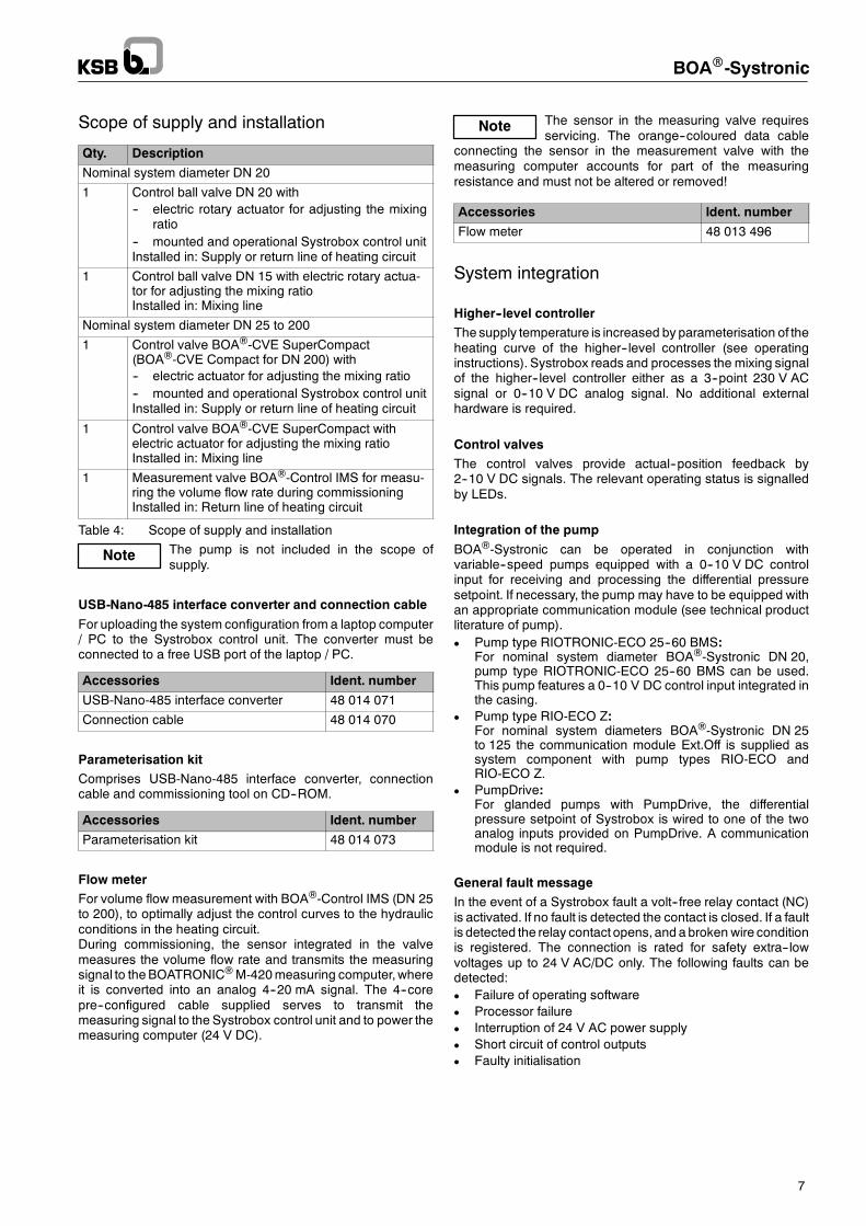
Integration in building management systems
BOA®-Systronic computes the travel setpoints for both controlvalves and the differential pressure setpoint for the pump andtransmits the values as 0--10 V DC signals. BOA®-Systronicdoes not have a separate data interface.The differential pressure setpoint transmitted to the pump canbe accessed via the data interface of the pump (see technicalproduct literature of pump). The actual--position feedback of thecontrol valves can be processed as a 2--10 V DC signal.
Data interfaces
Fig. 8: Data interfaces
1 Higher--level controller2 BOA®-Systronic and pump3 Interface converter4 System bus5 Building management system (BMS)
Glandless pump RIOTRONIC-ECO 25--60 BMSThe RIOTRONIC-ECO 25--60BMS pumpdoes not have a datainterface but it can signal a general fault (general faultmessage,SSM). It can be started and stopped by means of an externalsignal (Ext.Off).
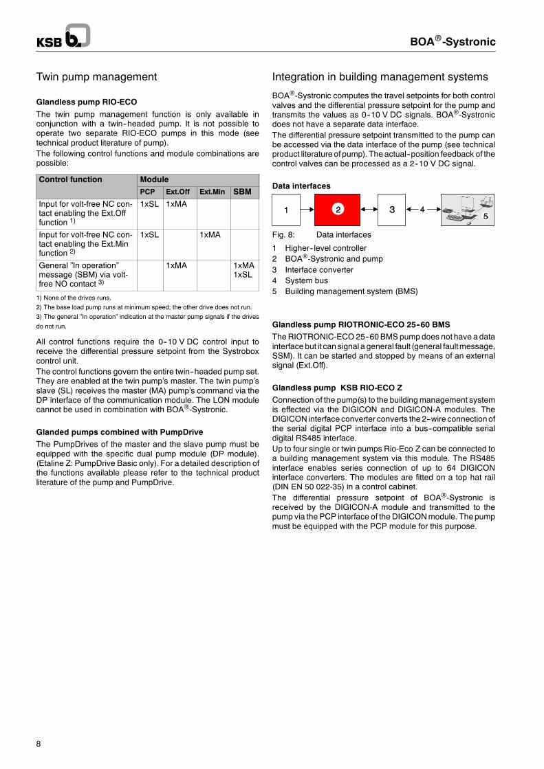
Glandless pump KSB RIO-ECO ZConnection of the pump(s) to the building management systemis effected via the DIGICON and DIGICON-A modules. TheDIGICON interface converter converts the 2--wire connectionofthe serial digital PCP interface into a bus--compatible serialdigital RS485 interface.Up to four single or twin pumps Rio-Eco Z can be connected toa building management system via this module. The RS485interface enables series connection of up to 64 DIGICONinterface converters. The modules are fitted on a top hat rail(DIN EN 50 022-35) in a control cabinet.The differential pressure setpoint of BOA®-Systronic isreceived by the DIGICON-A module and transmitted to thepump via the PCP interface of the DIGICONmodule. The pumpmust be equipped with the PCP module for this purpose.
BOAR-Systronic
9
Fig. 9: Data interface of RIO-ECO Z pump incombination with BOA®-Systronic
1 Higher--level controller2 BOA®-Systronic and pump3 Interface converter
Bi--directional communication between the pumps and abuilding management system (BMS) enables remote controland remote monitoring of the following operating modes andparameters. In the event of a fault in the RS485 connection, thepump will continue to operate on the basis of the last buscommand received.
Remote control Remote monitoring
D Pump OFFD Pump in closed--loop
control mode OND Maximum speedD Minimum speed
(reduced speed opera-tion)
D Setpoint for set closed--loop or open--loop controlmode
D Current operating modeD General fault messageD Individual ”In operation”
message MA or singlepump
D Individual ”In operation”message SL (twin pumponly)
D Actual discharge headD Actual volume flow rateD Motor currentD Power inputD Operating hoursD Cumulated energy con-
sumptionD Rotational speedD Fluid temperature
The closed--loop or open--loop control mode of the pumps canbe set either locally or remotely via a building managementsystem.D ∆p--c for constant differential pressureD ∆p--c for variable differential pressureD n--c for constant rotational speedD Setpoint for differential pressure or rotational speedThe DIGICON interface converter is equipped with LEDssignallingD Operational availability of DIGICOND Communication with the pumpD Communication with the RS485 interface
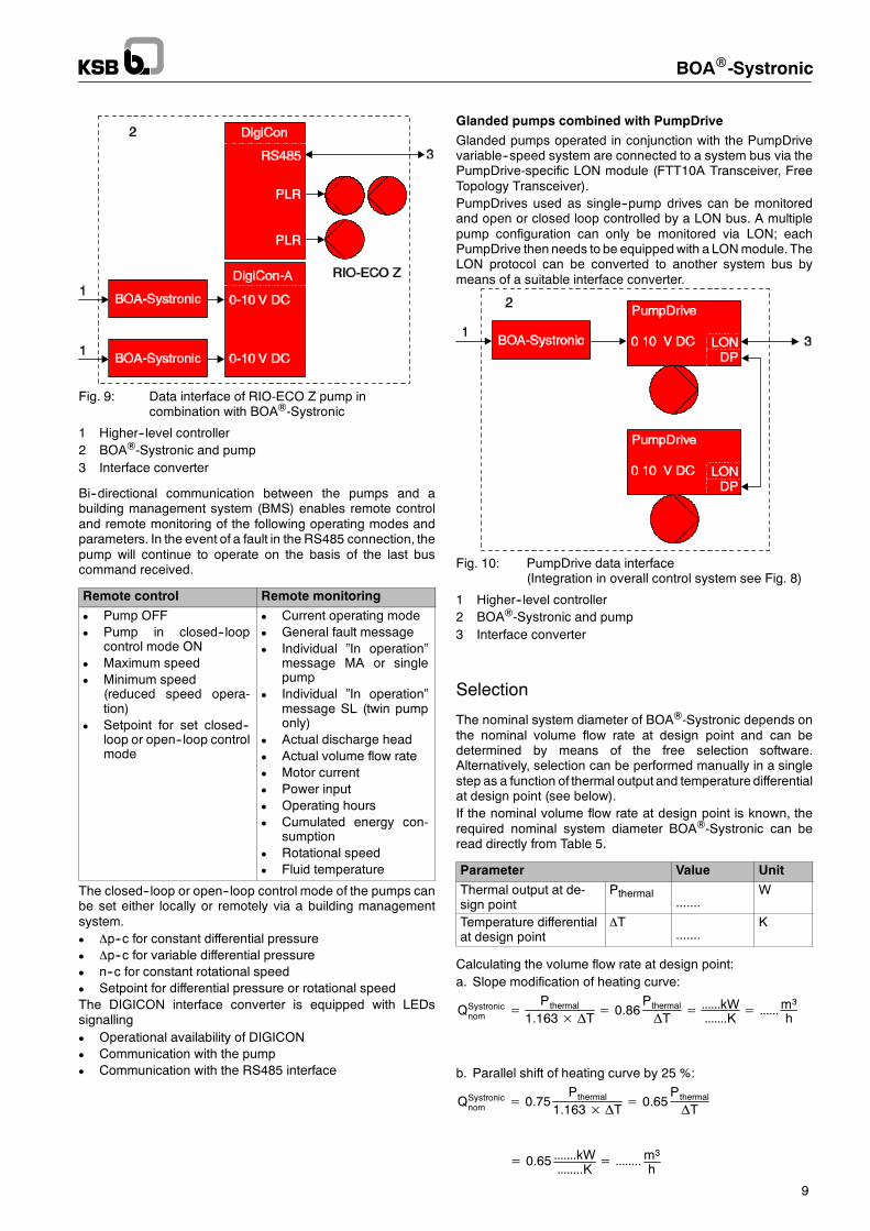
Glanded pumps combined with PumpDrive
Glanded pumps operated in conjunction with the PumpDrivevariable--speed system are connected to a system bus via thePumpDrive-specific LON module (FTT10A Transceiver, FreeTopology Transceiver).PumpDrives used as single--pump drives can be monitoredand open or closed loop controlled by a LON bus. A multiplepump configuration can only be monitored via LON; eachPumpDrive then needs to be equippedwith a LONmodule. TheLON protocol can be converted to another system bus bymeans of a suitable interface converter.
Fig. 10: PumpDrive data interface(Integration in overall control system see Fig. 8)
1 Higher--level controller2 BOA®-Systronic and pump3 Interface converter
Selection
The nominal system diameter of BOA®-Systronic depends onthe nominal volume flow rate at design point and can bedetermined by means of the free selection software.Alternatively, selection can be performed manually in a singlestep as a function of thermal output and temperature differentialat design point (see below).If the nominal volume flow rate at design point is known, therequired nominal system diameter BOA®-Systronic can beread directly from Table 5.
Parameter Value Unit
Thermal output at de-sign point
Pthermal.......
W
Temperature differentialat design point
∆T.......
K
Calculating the volume flow rate at design point:a. Slope modification of heating curve:
QSystronicnom =
Pthermal
1.163× ΔT= 0.86Pthermal
ΔT= kW.K =
m3
h
b. Parallel shift of heating curve by 25 %:
QSystronicnom = 0.75
Pthermal
1.163× ΔT= 0.65Pthermal
ΔT
= 0.65 .kW..K = ..m3
h
Example
BOAR-Systronic
10
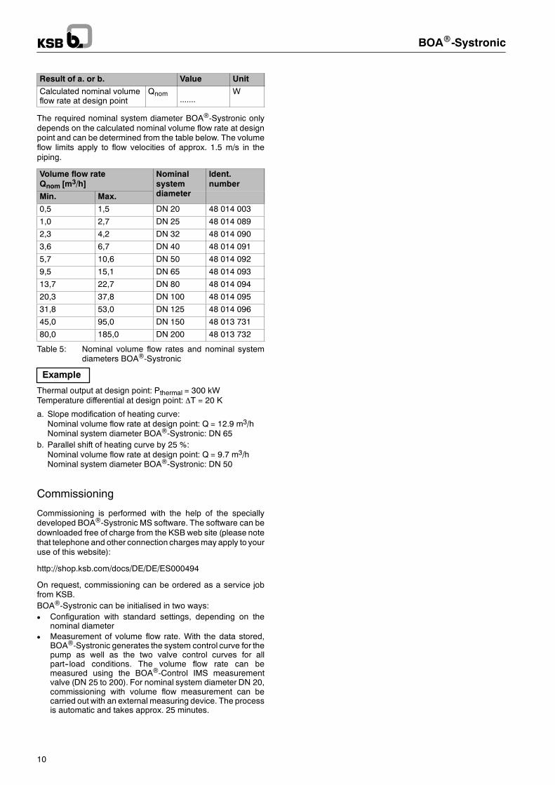
Result of a. or b. Value Unit
Calculated nominal volumeflow rate at design point
Qnom.......
W
The required nominal system diameter BOA®-Systronic onlydepends on the calculated nominal volume flow rate at designpoint and can be determined from the table below. The volumeflow limits apply to flow velocities of approx. 1.5 m/s in thepiping.
Volume flow rateQnom [m3/h]
Nominalsystemdi
Ident.number
Min. Max.
ydiameter
0,5 1,5 DN 20 48 014 003
1,0 2,7 DN 25 48 014 089
2,3 4,2 DN 32 48 014 090
3,6 6,7 DN 40 48 014 091
5,7 10,6 DN 50 48 014 092
9,5 15,1 DN 65 48 014 093
13,7 22,7 DN 80 48 014 094
20,3 37,8 DN 100 48 014 095
31,8 53,0 DN 125 48 014 096
45,0 95,0 DN 150 48 013 731
80,0 185,0 DN 200 48 013 732
Table 5: Nominal volume flow rates and nominal systemdiameters BOA®-Systronic
Thermal output at design point: Pthermal = 300 kWTemperature differential at design point: ∆T = 20 K
a. Slope modification of heating curve:Nominal volume flow rate at design point: Q = 12.9 m3/hNominal system diameter BOA®-Systronic: DN 65
b. Parallel shift of heating curve by 25 %:Nominal volume flow rate at design point: Q = 9.7 m3/hNominal system diameter BOA®-Systronic: DN 50
Commissioning
Commissioning is performed with the help of the speciallydeveloped BOA®-Systronic MS software. The software can bedownloaded free of charge from the KSB web site (please notethat telephone and other connection charges may apply to youruse of this website):
http://shop.ksb.com/docs/DE/DE/ES000494
On request, commissioning can be ordered as a service jobfrom KSB.BOA®-Systronic can be initialised in two ways:D Configuration with standard settings, depending on the
nominal diameterD Measurement of volume flow rate. With the data stored,
BOA®-Systronic generates the system control curve for thepump as well as the two valve control curves for allpart--load conditions. The volume flow rate can bemeasured using the BOA®-Control IMS measurementvalve (DN 25 to 200). For nominal system diameter DN 20,commissioning with volume flow measurement can becarried out with an external measuring device. The processis automatic and takes approx. 25 minutes.
BOAR-Systronic
11
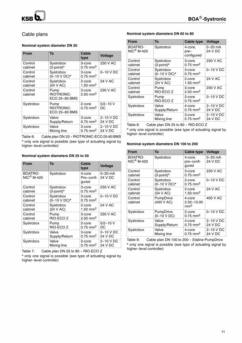
Cable plans
Nominal system diameter DN 20
From To Cabletype Voltage
Controlcabinet
Systrobox(3-point)*
3-core0.75 mm2
230 V AC
Controlcabinet
Systrobox(0--10 V DC)*
3-core0.75 mm2
0--10 V DC
Controlcabinet
Systrobox(24 V AC)
2-core1.50 mm2
24 V AC
Controlcabinet
PumpRIOTRONIC-ECO 25--60 BMS
3-core2.50 mm2
230 V AC
Systrobox PumpRIOTRONIC-ECO 25--60 BMS
2-core0.75 mm2
0/2--10 VDC
Systrobox ValveSupply/Return
3-core0.75 mm2
2--10 V DC24 V DC
Systrobox ValveMixing line
3-core0.75 mm2
2--10 V DC24 V DC
Table 6: Cable plan DN 20 -- RIOTRONIC-ECO 25-60BMS* only one signal is possible (see type of actuating signal byhigher--level controller)
Nominal system diameters DN 25 to 50
From To Cabletype Voltage
BOATRO-NIC® M-420
Systrobox 4-corePre--confi-gured
0--20 mA24 V DC
Controlcabinet
Systrobox(3-point)*
3-core0.75 mm2
230 V AC
Controlcabinet
Systrobox(0--10 V DC)*
3-core0.75 mm2
0--10 V DC
Controlcabinet
Systrobox(24 V AC)
2-core1.50 mm2
24 V AC
Controlcabinet
PumpRIO-ECO Z
3-core2.50 mm2
230 V AC
Systrobox PumpRIO-ECO Z
2-core0.75 mm2
0/2--10 VDC
Systrobox ValveSupply/Return
3-core0.75 mm2
2--10 V DC24 V DC
Systrobox ValveMixing line
3-core0.75 mm2
2--10 V DC24 V DC
Table 7: Cable plan DN 25 to 80 -- RIO-ECO Z* only one signal is possible (see type of actuating signal byhigher--level controller)
Nominal system diameters DN 65 to 80
From To Cable type Voltage
BOATRO-NIC® M-420
Systrobox 4-core,pre--configured
0--20 mA24 V DC
Controlcabinet
Systrobox(3-point)*
3-core0.75 mm2
230 V AC
Controlcabinet
Systrobox(0--10 V DC)*
3-core0.75 mm2
0--10 V DC
Controlcabinet
Systrobox(24 V AC)
2-core1.50 mm2
24 V AC
Controlcabinet
PumpRIO-ECO Z
3-core2.50 mm2
230 V AC
Systrobox PumpRIO-ECO Z
2-core0.75 mm2
0--10 V DC
Systrobox ValveSupply/Return
4-core0.75 mm2
2--10 V DC24 V DC
Systrobox ValveMixing line
3-core0.75 mm2
2--10 V DC24 V DC
Table 8: Cable plan DN 25 to 80 -- RIO-ECO Z* only one signal is possible (see type of actuating signal byhigher--level controller)
Nominal system diameters DN 100 to 200
From To Cable type Voltage
BOATRO-NIC® M-420
Systrobox 4-core,pre--confi-gured
0--20 mA24 V DC
Controlcabinet
Systrobox(3-point)*
3-core0.75 mm2
230 V AC
Controlcabinet
Systrobox(0--10 V DC)*
2-core0.75 mm2
0--10 V DC
Controlcabinet
Systrobox(24 V AC)
2-core1.50 mm2
24 V AC
Controlcabinet
PumpDrive(400 V AC)
4-core2.50--10.00mm2
400 V AC
Systrobox PumpDrive(0--10 V DC)
2-core0.75 mm2
0--10 V DC
Systrobox ValveSupply/Return
4-core0.75 mm2
2--10 V DC24 V DC
Systrobox ValveMixing line
4-core0.75 mm2
2--10 V DC24 V DC
Table 9: Cable plan DN 100 to 200 -- Etaline-PumpDrive* only one signal is possible (see type of actuating signal byhigher--level controller)
BOAR-Systronic
12
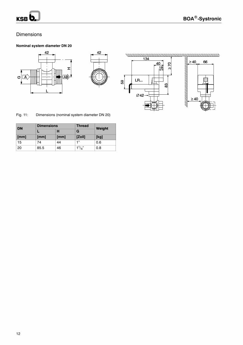
Dimensions
Nominal system diameter DN 20
Fig. 11: Dimensions (nominal system diameter DN 20)
DNDimensions Thread
WeightDNL H G
Weight
[mm] [mm] [mm] [Zoll] [kg]
15 74 44 1” 0.6
20 85.5 46 11/4” 0.8
BOAR-Systronic
13
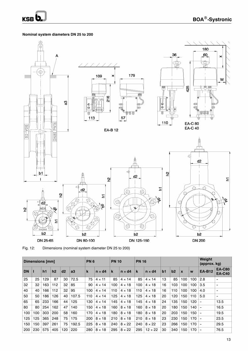
Nominal system diameters DN 25 to 200
Fig. 12: Dimensions (nominal system diameter DN 25 to 200)
Dimensions [mm] PN 6 PN 10 PN 16 Weight(approx. kg)
DN l h1 h2 d2 a3 k n × d4 k n × d4 k n × d4 b1 b2 x w EA-B12 EA-C80EA-C40
25 25 129 87 30 72.5 75 4 × 11 85 4 × 14 85 4 × 14 13 85 100 100 2.8 --
32 32 163 112 32 85 90 4 × 14 100 4 × 18 100 4 × 18 16 103 100 100 3.5 --
40 40 166 112 32 95 100 4 × 14 110 4 × 18 110 4 × 18 16 110 100 100 4.0 --
50 50 186 126 40 107.5 110 4 × 14 125 4 × 18 125 4 × 18 20 120 150 110 5.0 --
65 65 233 166 44 125 130 4 × 14 145 4 × 18 145 4 × 18 24 135 150 120 -- 13.5
80 80 254 162 47 140 150 4 × 18 160 8 × 18 160 8 × 18 20 180 150 140 -- 16.5
100 100 303 200 58 160 170 4 × 18 180 8 × 18 180 8 × 18 20 203 150 150 -- 19.5
125 125 365 248 75 175 200 8 × 18 210 8 × 18 210 8 × 18 23 230 150 170 -- 23.5
150 150 397 261 75 192.5 225 8 × 18 240 8 × 22 240 8 × 22 23 266 150 170 -- 29.5
200 230 575 405 120 220 280 8 × 18 295 8 × 22 295 12 × 22 30 340 150 170 -- 76.5
BOAR-Systronic
14
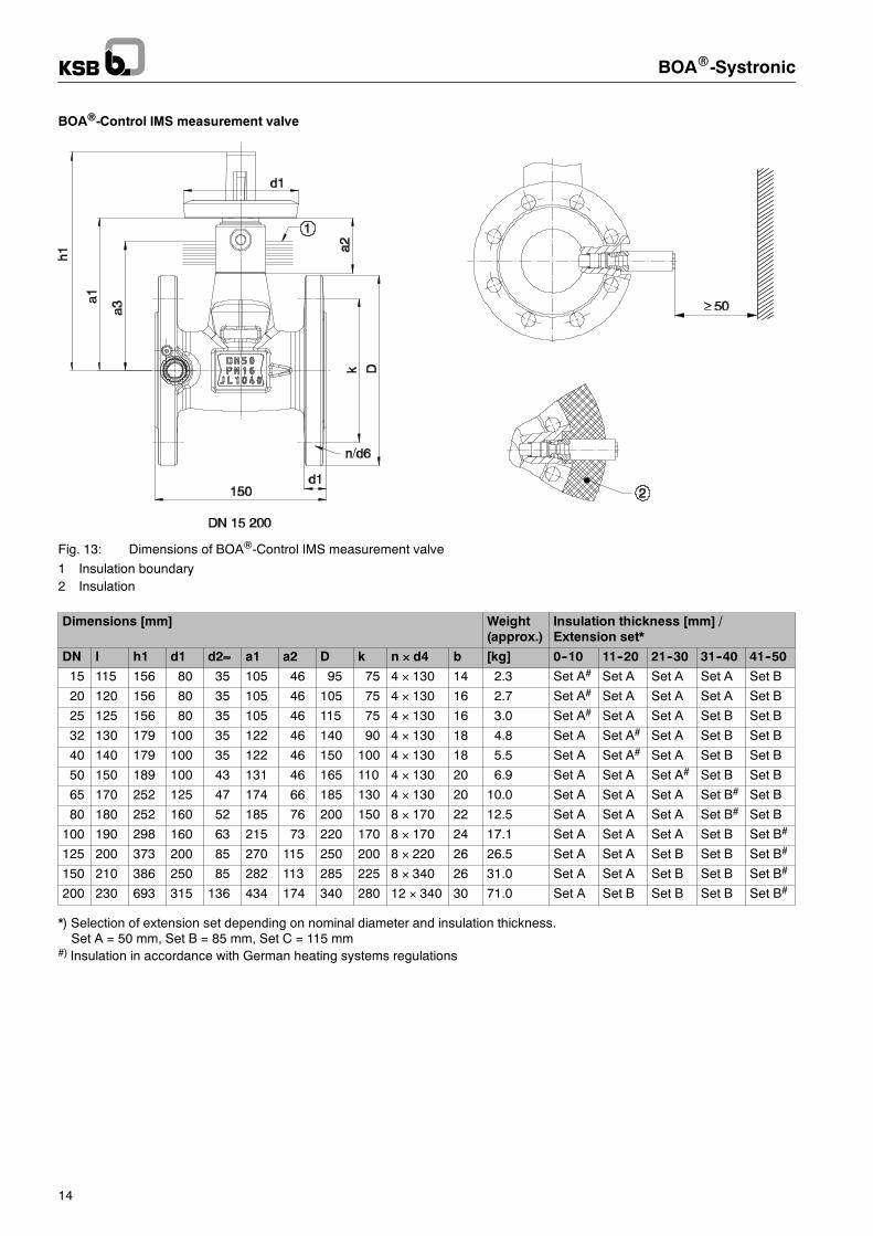
BOA®-Control IMS measurement valve
Fig. 13: Dimensions of BOA®-Control IMS measurement valve1 Insulation boundary2 Insulation
Dimensions [mm] Weight(approx.)
Insulation thickness [mm] /Extension set*
DN l h1 d1 d2≈ a1 a2 D k n × d4 b [kg] 0--10 11--20 21--30 31--40 41--50
15 115 156 80 35 105 46 95 75 4 × 130 14 2.3 Set A# Set A Set A Set A Set B
20 120 156 80 35 105 46 105 75 4 × 130 16 2.7 Set A# Set A Set A Set A Set B
25 125 156 80 35 105 46 115 75 4 × 130 16 3.0 Set A# Set A Set A Set B Set B
32 130 179 100 35 122 46 140 90 4 × 130 18 4.8 Set A Set A# Set A Set B Set B
40 140 179 100 35 122 46 150 100 4 × 130 18 5.5 Set A Set A# Set A Set B Set B
50 150 189 100 43 131 46 165 110 4 × 130 20 6.9 Set A Set A Set A# Set B Set B
65 170 252 125 47 174 66 185 130 4 × 130 20 10.0 Set A Set A Set A Set B# Set B
80 180 252 160 52 185 76 200 150 8 × 170 22 12.5 Set A Set A Set A Set B# Set B
100 190 298 160 63 215 73 220 170 8 × 170 24 17.1 Set A Set A Set A Set B Set B#
125 200 373 200 85 270 115 250 200 8 × 220 26 26.5 Set A Set A Set B Set B Set B#
150 210 386 250 85 282 113 285 225 8 × 340 26 31.0 Set A Set A Set B Set B Set B#
200 230 693 315 136 434 174 340 280 12 × 340 30 71.0 Set A Set B Set B Set B Set B#
*) Selection of extension set depending on nominal diameter and insulation thickness.Set A = 50 mm, Set B = 85 mm, Set C = 115 mm
#) Insulation in accordance with German heating systems regulations
BOAR-Systronic
15
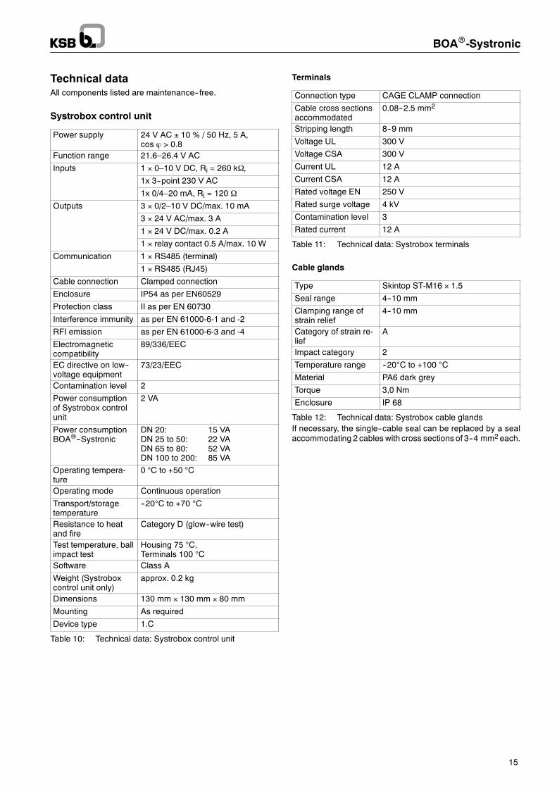
Technical dataAll components listed are maintenance--free.
Systrobox control unit
Power supply 24 V AC ± 10 % / 50 Hz, 5 A,cos ϕ > 0.8
Function range 21.6–26.4 V AC
Inputs 1 × 0–10 V DC, Ri = 260 kΩ,p
1x 3--point 230 V AC
1x 0/4–20 mA, Ri = 120 Ω
Outputs 3 × 0/2–10 V DC/max. 10 mAp
3 × 24 V AC/max. 3 A
1 × 24 V DC/max. 0.2 A
1 × relay contact 0.5 A/max. 10 W
Communication 1 × RS485 (terminal)
1 × RS485 (RJ45)
Cable connection Clamped connection
Enclosure IP54 as per EN60529
Protection class II as per EN 60730
Interference immunity as per EN 61000-6-1 and -2
RFI emission as per EN 61000-6-3 and -4
Electromagneticcompatibility
89/336/EEC
EC directive on low--voltage equipment
73/23/EEC
Contamination level 2
Power consumptionof Systrobox controlunit
2 VA
Power consumptionBOA®--Systronic
DN 20: 15 VADN 25 to 50: 22 VADN 65 to 80: 52 VADN 100 to 200: 85 VA
Operating tempera-ture
0 °C to +50 °C
Operating mode Continuous operation
Transport/storagetemperature
--20°C to +70 °C
Resistance to heatand fire
Category D (glow--wire test)
Test temperature, ballimpact test
Housing 75 °C,Terminals 100 °C
Software Class A
Weight (Systroboxcontrol unit only)
approx. 0.2 kg
Dimensions 130 mm × 130 mm × 80 mm
Mounting As required
Device type 1.C
Table 10: Technical data: Systrobox control unit
Terminals
Connection type CAGE CLAMP connection
Cable cross sectionsaccommodated
0.08--2.5 mm2
Stripping length 8--9 mm
Voltage UL 300 V
Voltage CSA 300 V
Current UL 12 A
Current CSA 12 A
Rated voltage EN 250 V
Rated surge voltage 4 kV
Contamination level 3
Rated current 12 A
Table 11: Technical data: Systrobox terminals
Cable glands
Type Skintop ST-M16 × 1.5
Seal range 4--10 mm
Clamping range ofstrain relief
4--10 mm
Category of strain re-lief
A
Impact category 2
Temperature range --20°C to +100 °C
Material PA6 dark grey
Torque 3,0 Nm
Enclosure IP 68
Table 12: Technical data: Systrobox cable glandsIf necessary, the single--cable seal can be replaced by a sealaccommodating 2 cables with cross sections of 3--4 mm2each.
BOAR-Systronic
16
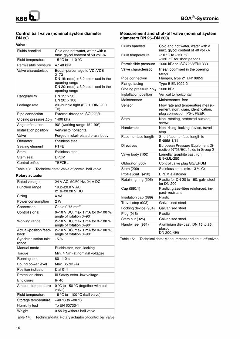
Control ball valve (nominal system diameterDN 20)
Valve
Fluids handled Cold and hot water, water with amax. glycol content of 50 vol.-%
Fluid temperature +5 °C to +110 °C
Permissible pressure 4.140 kPa
Valve characteristic Equal--percentage to VDI/VDE2173DN 15: n(eq) = 3.2 optimised in theopening rangeDN 20: n(eq) = 3.9 optimised in theopening range
Rangeability DN 15: > 50DN 20: > 100
Leakage rate Air--bubble tight (BO 1, DIN3230T3)
Pipe connection External thread to ISO 228/1
Closing pressure ∆pC 1400 kPa
Angle of rotation 90° (working range 15°–90°)
Installation position Vertical to horizontal
Valve Forged; nickel--plated brass body
Obturator Stainless steel
Sealing element PTFE
Stem Stainless steel
Stem seal EPDM
Control orifice TEFZEL
Table 13: Technical data: Valve of control ball valve
Rotary actuator
Rated voltage 24 V AC, 50/60 Hz, 24 V DC
Function range 19.2–28.8 V AC21.6–28.28 V DC
Sizing 4 VA
Power consumption 2 W
Connection Cable 0.75 mm2
Control signal 0–10 V DC, max 1 mA for 0–100 %,angle of rotation 0–90°
Working range 2–10 V DC, max 1 mA for 0–100 %,angle of rotation 0–90°
Actual--position feed-back
2–10 V DC, max 1 mA for 0–100 %,angle of rotation 0–90°
Synchronisation tole-rance
±5 %
Manual mode Pushbutton, non--locking
Torque Min. 4 Nm (at nominal voltage)
Running time 80–110 s
Sound power level Max. 35 dB (A)
Position indicator Dial 0–1
Protection class III Safety extra--low voltage
Enclosure IP 40
Ambient temperature 0 °C to +50 °C (together with ballvalve)
Fluid temperature +5 °C to +100 °C (ball valve)
Storage temperature --40 °C to +80 °C
Humidity test To EN 60730-1
Weight 0.55 kg without ball valve
Table 14: Technical data:Rotary actuator of control ball valve
Measurement and shut--off valve (nominal systemdiameters DN 25–DN 200)
Fluids handled Cold and hot water, water with amax. glycol content of 40 vol.-%
Fluid temperature --10 °C to +120 °C,+130 °C for short periods
Permissible pressure 1600 kPa to ISO7268/EN1333
Valve characteristic linear, optimised in the openingrange
Pipe connection Flanges, type 21 EN1092-2
Flange facing Type B EN1092-2
Closing pressure ∆pC 1600 kPa
Installation position Vertical to horizontal
Maintenance Maintenance--free
Sensor Flow rate and temperature measu-rement, nom. diam. identification,plug connection IP54, PEEK
Stem Non--rotating, protected outsidescrew
Handwheel Non--rising, locking device, travelstop
Face--to--face length Short face--to--face length toEN558-1/14
Directives European Pressure Equipment Di-rective 97/23/EC, fluids in Group 2
Valve body (100) Lamellar graphite cast ironEN-GJL-250
Obturator (350) Control valve plug GG/EPDM
Stem (200) Stainless steel, min. 13 % Cr
Profile joint (410) EPDM elastomer
Retaining ring (506) Plastic for DN 20 to 150, galv. steelfor DN 200
Cap (580.1) Plastic, glass--fibre reinforced, im-pact--resistant
Insulation cap (689) Plastic
Travel stop (903) Galvanised steel
Locking device (904) Galvanised steel
Plug (916) Plastic
Stem nut (925) Galvanised steel
Handwheel (961) Aluminium die--cast, DN 15 to 25:plasticDN 200: GG
Table 15: Technical data: Measurement and shut--off valves
BOAR-Systronic
17
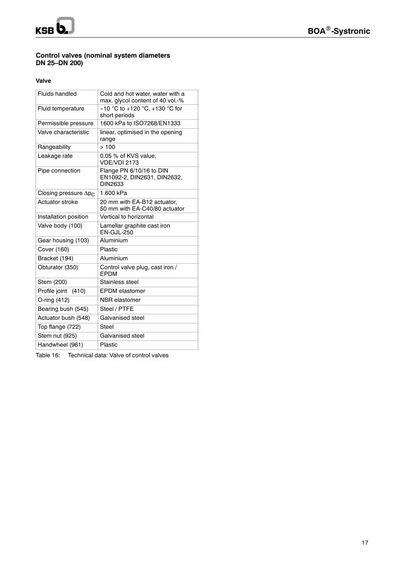
Control valves (nominal system diametersDN 25–DN 200)
Valve
Fluids handled Cold and hot water, water with amax. glycol content of 40 vol.-%
Fluid temperature --10 °C to +120 °C, +130 °C forshort periods
Permissible pressure 1600 kPa to ISO7268/EN1333
Valve characteristic linear, optimised in the openingrange
Rangeability > 100
Leakage rate 0.05 % of KVS value,VDE/VDI 2173
Pipe connection Flange PN 6/10/16 to DINEN1092-2, DIN2631, DIN2632,DIN2633
Closing pressure ∆pC 1.600 kPa
Actuator stroke 20 mm with EA-B12 actuator,50 mm with EA-C40/80 actuator
Installation position Vertical to horizontal
Valve body (100) Lamellar graphite cast ironEN-GJL-250
Gear housing (103) Aluminium
Cover (160) Plastic
Bracket (194) Aluminium
Obturator (350) Control valve plug, cast iron /EPDM
Stem (200) Stainless steel
Profile joint (410) EPDM elastomer
O-ring (412) NBR elastomer
Bearing bush (545) Steel / PTFE
Actuator bush (548) Galvanised steel
Top flange (722) Steel
Stem nut (925) Galvanised steel
Handwheel (961) Plastic
Table 16: Technical data: Valve of control valves
BOAR-Systronic
18
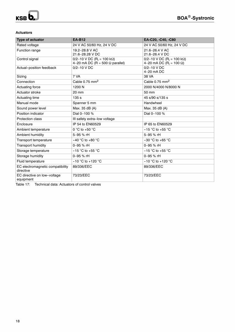
Actuators
Type of actuator EA-B12 EA-C20, -C40, -C80
Rated voltage 24 V AC 50/60 Hz, 24 V DC 24 V AC 50/60 Hz, 24 V DC
Function range 19.2–28.8 V AC21.6–28.28 V DC
21.6–26.4 V AC21.6–26.4 V DC
Control signal 0/2–10 V DC (Ri = 100 kΩ)4–20 mA DC (R = 500 Ω parallel)
0/2–10 V DC (Ri = 100 kΩ)4–20 mA DC (Ri = 100 Ω)
Actual--position feedback 0/2–10 V DC 0/2–10 V DC4–20 mA DC
Sizing 7 VA 38 VA
Connection Cable 0.75 mm2 Cable 0.75 mm2
Actuating force 1200 N 2000 N/4000 N/8000 N
Actuator stroke 20 mm 50 mm
Actuating time 135 s 45 s/90 s/135 s
Manual mode Spanner 5 mm Handwheel
Sound power level Max. 35 dB (A) Max. 35 dB (A)
Position indicator Dial 0–100 % Dial 0–100 %
Protection class III safety extra--low voltage
Enclosure IP 54 to EN60529 IP 65 to EN60529
Ambient temperature 0 °C to +50 °C --15 °C to +55 °C
Ambient humidity 5–95 % rH 5–95 % rH
Transport temperature --40 °C to +80 °C --30 °C to +65 °C
Transport humidity 0–95 % rH 0–95 % rH
Storage temperature --15 °C to +55 °C --15 °C to +55 °C
Storage humidity 0–95 % rH 0–95 % rH
Fluid temperature --10 °C to +120 °C --10 °C to +120 °C
EC electromagnetic compatibilitydirective
89/336/EEC 89/336/EEC
EC directive on low--voltageequipment
73/23/EEC 73/23/EEC
Table 17: Technical data: Actuators of control valves
BOAR-Systronic
19
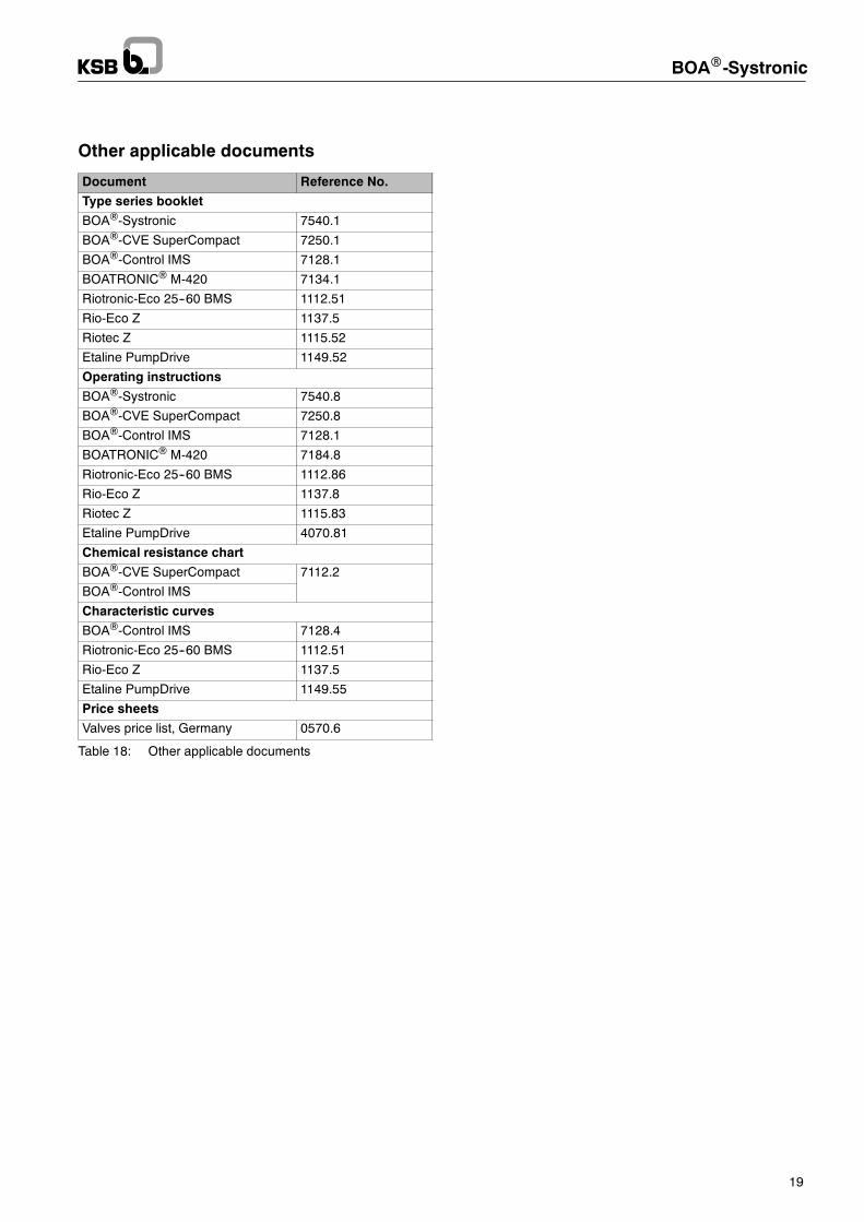
Other applicable documents
Document Reference No.
Type series booklet
BOA®-Systronic 7540.1
BOA®-CVE SuperCompact 7250.1
BOA®-Control IMS 7128.1
BOATRONIC® M-420 7134.1
Riotronic-Eco 25--60 BMS 1112.51
Rio-Eco Z 1137.5
Riotec Z 1115.52
Etaline PumpDrive 1149.52
Operating instructions
BOA®-Systronic 7540.8
BOA®-CVE SuperCompact 7250.8
BOA®-Control IMS 7128.1
BOATRONIC® M-420 7184.8
Riotronic-Eco 25--60 BMS 1112.86
Rio-Eco Z 1137.8
Riotec Z 1115.83
Etaline PumpDrive 4070.81
Chemical resistance chart
BOA®-CVE SuperCompact 7112.2
BOA®-Control IMS
Characteristic curves
BOA®-Control IMS 7128.4
Riotronic-Eco 25--60 BMS 1112.51
Rio-Eco Z 1137.5
Etaline PumpDrive 1149.55
Price sheets
Valves price list, Germany 0570.6
Table 18: Other applicable documents
BOAR-Systronic
20
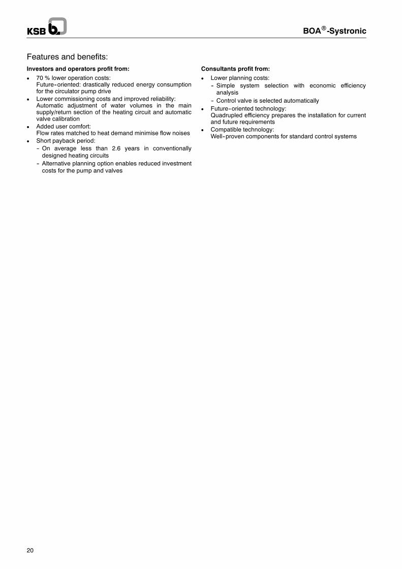
Features and benefits:Investors and operators profit from:
D 70 % lower operation costs:Future--oriented: drastically reduced energy consumptionfor the circulator pump drive
D Lower commissioning costs and improved reliability:Automatic adjustment of water volumes in the mainsupply/return section of the heating circuit and automaticvalve calibration
D Added user comfort:Flow rates matched to heat demand minimise flow noises
D Short payback period:-- On average less than 2.6 years in conventionallydesigned heating circuits
-- Alternative planning option enables reduced investmentcosts for the pump and valves
Consultants profit from:
D Lower planning costs:-- Simple system selection with economic efficiencyanalysis
-- Control valve is selected automaticallyD Future--oriented technology:
Quadrupled efficiency prepares the installation for currentand future requirements
D Compatible technology:Well--proven components for standard control systems

BOAR-Systronic
21
Notes:

BOAR-Systronic
22
Notes:

BOAR-Systronic
23
Notes:
KSB Aktiengesellschaft67225 Frankenthal • Johann-Klein-Str. 9 • 67227 Frankenthal (Germany)Tel. +49 6233 86-0 • Fax +49 6233 86-3476 • www.ksb.com
Subjecttotechnicalm
odificationwithoutpriornotice.
19.06.2008
7540.1/7--10
BOAR Systronic