Embed Size (px)
Citation preview

R. N. G . Patel Instituteof Technology, Bardoli
Subject: Material Science and MetallurgySubject Code: 3131904Topic : Ion-Carbon EquilibriumDiagram
Dr. K. B. RathodAssociate professor
Mechanical Engineering DepartmentRNGPIT (084)- Bardoli
Subject: Material Science and MetallurgySubject Code: 3131904Topic : Ion-Carbon EquilibriumDiagram
IronIron--Carbon systemCarbon system• Alloys of the Iron-carbon system include steel and cast iron• Alloy with carbon content up to 2% are known as steels whereas
these having carbon above 2% are called cast-irons• Alloys of the iron-carbon system are of the most vital important to
modern industry due to their extensive, versatile applications.• The iron-carbon system provides the most prominent example of
the heat treatment and properly alteration based on polymorphictransformation (Change in the atomic structure to produce adifferent form) and eutectoid decomposition.
• Because of its outstanding commercial importance, the iron-carbon system has been studied in more detail than most alloysystems
• The primary constituent of Iron-Carbon system is the metal Iron.
• Alloys of the Iron-carbon system include steel and cast iron• Alloy with carbon content up to 2% are known as steels whereas
these having carbon above 2% are called cast-irons• Alloys of the iron-carbon system are of the most vital important to
modern industry due to their extensive, versatile applications.• The iron-carbon system provides the most prominent example of
the heat treatment and properly alteration based on polymorphictransformation (Change in the atomic structure to produce adifferent form) and eutectoid decomposition.
• Because of its outstanding commercial importance, the iron-carbon system has been studied in more detail than most alloysystems
• The primary constituent of Iron-Carbon system is the metal Iron.

Iron Allotropy :Iron Allotropy :

Iron Carbon Equilibrium DiagramIron Carbon Equilibrium Diagram
• It shows ranges of temperatures and composition withinwhich the various phase changes are stable and also theboundaries at which the phase changes occur.
• It indicates the phase changes that occur during heating andcooling and the nature and amount of the structuralcomponents that exist at any temperature.
• It is helpful to understand the principles of heat treatment.


Critical TemperaturesCritical Temperatures
• A0 : 210˚ C -------- Change in magnetic properties of cementite.
• A1 : 727˚ C -------- Eutectoid transformation.
• A2 : 768˚ C --------- Changes in magnetic properties of ferrite.
• A3 : 910 – 727˚ C – Change in solubility of pro-eutectoid ferritein austenite.
• ACM : 723 - 1147˚ C –Change in solubility of pro-eutectoidcementite in austenite.

TransformationsTransformations• It means the changes occur in phases at a
particular temperature and a particularcomposition.
• Three transformations observed in the Fe-Fe3C equilibrium diagram.1. Peritectic transformation2. Eutectic transformation3. Eutectoid transformation
• It means the changes occur in phases at aparticular temperature and a particularcomposition.
• Three transformations observed in the Fe-Fe3C equilibrium diagram.1. Peritectic transformation2. Eutectic transformation3. Eutectoid transformation

Peritectic transformationPeritectic transformation• Temperature : 1495˚ C• Composition : 0.18 % C• Reaction : Liquid + solid1 = solid2
so at peritectic temperatureliquid (0.53 % C)+ δ iron (0.095%) = γ iron (0.18 %C)

Eutectic transformationEutectic transformation• Temperature : 1147˚ C• Composition : 4.3 % C• Reaction : Liquid = solid1 + solid2
so at eutectic temperatureliquid (4.3 % C) = γ iron (2 % C) + Fe3C (6.67% C)
• Temperature : 1147˚ C• Composition : 4.3 % C• Reaction : Liquid = solid1 + solid2
so at eutectic temperatureliquid (4.3 % C) = γ iron (2 % C) + Fe3C (6.67% C)

Eutectoid transformationEutectoid transformation• Temperature : 727˚ C• Composition : 0.83 % C• Reaction : solid1 = solid2 + solid3
so at eutectoid temperatureγ iron (0.83 % C) = α iron (0.025 % C) + Fe3C (6.67% C)
•Austenite is decomposed withsimultaneous precipitation of ferrite& cementite. (Pearlite)•Steels contains eutectoidcomposition are called eutectoidsteels. Which cooled in equilibriumshows 100% Pearlite.•Steel contain less than 0.83% C arecalled Hypoeutectoid steels.•Steel contain more than 0.83% Care called Hypereutectoid steels.
•Austenite is decomposed withsimultaneous precipitation of ferrite& cementite. (Pearlite)•Steels contains eutectoidcomposition are called eutectoidsteels. Which cooled in equilibriumshows 100% Pearlite.•Steel contain less than 0.83% C arecalled Hypoeutectoid steels.•Steel contain more than 0.83% Care called Hypereutectoid steels.

Cooling of Hypoeutectoid SteelCooling of Hypoeutectoid Steel0.4% C

Cooling of Hypereutectoid SteelCooling of Hypereutectoid Steel1.2% C


Crystalline Structure of SteelCrystalline Structure of Steel• Coarse crystalline structure induces weakness
and brittleness.
• Fine grain structure gives strength and ductility.
• By mechanical treatment above the critical rangeand proper Heat treatment, grain or crystallinestructure can be refined.
• Coarse crystalline structure induces weaknessand brittleness.
• Fine grain structure gives strength and ductility.
• By mechanical treatment above the critical rangeand proper Heat treatment, grain or crystallinestructure can be refined.

• Alloying is changing chemical composition of steelby adding elements with purpose to improve itsproperties as compared to the plane carbon steel.
• The properties, which may be improved1. Stabilizing austenite – increasing the temperature
range, in which austenite exists.– The elements, having the same crystal structure as that
of austenite (cubic face centered – FCC), raise the A4point (the temperature of formation of austenite fromliquid phase) and decrease the A3 temperature.
– These elements are nickel (Ni), manganese (Mn),cobalt (Co) and copper (Cu).
– Examples of austenitic steels: austenitic stainlesssteels, Hadfield steel (1%C, 13%Mn, 1.2%Cr).
Effect of Alloying Elements onEffect of Alloying Elements onProperties of SteelProperties of Steel
• Alloying is changing chemical composition of steelby adding elements with purpose to improve itsproperties as compared to the plane carbon steel.
• The properties, which may be improved1. Stabilizing austenite – increasing the temperature
range, in which austenite exists.– The elements, having the same crystal structure as that
of austenite (cubic face centered – FCC), raise the A4point (the temperature of formation of austenite fromliquid phase) and decrease the A3 temperature.
– These elements are nickel (Ni), manganese (Mn),cobalt (Co) and copper (Cu).
– Examples of austenitic steels: austenitic stainlesssteels, Hadfield steel (1%C, 13%Mn, 1.2%Cr).

• Stabilizing ferrite – decreasing the temperaturerange, in which austenite exists.
• The elements, having the same crystal structure as that offerrite (cubic body centered – BCC), lower the A4 point andincrease the A3 temperature.
• These elements lower the solubility of carbon in austenite,causing increase of amount of carbides in the steel.
• The following elements have ferrite stabilizing effect:chromium (Cr), tungsten (W), Molybdenum (Mo),vanadium (V), aluminum (Al) and silicon (Si).
• Examples of ferritic steels: transformer sheets steel (3%Si),F-Cr alloys.

• Carbide forming – elements forming hard carbides insteels.
• The elements like chromium (Cr), tungsten (W),molybdenum (Mo), vanadium (V), titanium (Ti), niobium(Nb), tantalum (Ta), zirconium (Zr) form hard (oftencomplex) carbides, increasing steel hardness and strength.
• Examples of steels containing relatively high concentrationof carbides: hot work tool steels, high speed steels.
• Carbide forming elements also form nitrides reacting withNitrogen in steels.

• Graphitizing – decreasing stability of carbides, promotingtheir breaking and formation of free Graphite.
• The following elements have graphitizing effect: silicon(Si), nickel (Ni), cobalt (Co), aluminum (Al).
• Decrease of the eutectoid concentration.• The following elements lower eutectoid concentration of
carbon: titanium (Ti), molybdenum (Mo), tungsten (W),silicon (Si), chromium (Cr), nickel (Ni).
• Increase of corrosion resistance.• Aluminum (Al), silicon (Si), and chromium (Cr) form thin an
strong oxide film on the steel surface, protecting it fromchemical attacks

Effect of Alloying Elements onEffect of Alloying Elements onProperties of SteelProperties of Steel
•• An alloying element is one which is added to a metal toAn alloying element is one which is added to a metal toeffect the changes in properties and which remains ineffect the changes in properties and which remains inthe metal.the metal.
• Common alloying elements : C, Ni, Cr, Mo, V, W, Mn, Cu,Bo, Al, Co, Si, Ti••Carbon :Carbon :
•Hardness•Tensilestrength•Machinability•Melting point
••Chromium :Chromium :•Joins with carbon to form chromiumcarbide•Improve hardenability, resistance toabrasion & wear•Helps preventing corrosion & oxidation•Add some strength at high temperature
••Carbon :Carbon :•Hardness•Tensilestrength•Machinability•Melting point••Nickel :Nickel :
•Increase toughness & resistance to impact•Lessens distortion in quenching•Lowers the critical temperatures of steel & widen the range of successful heattreatment•Strengthens the steel•Does not unite with carbon
••Chromium :Chromium :•Joins with carbon to form chromiumcarbide•Improve hardenability, resistance toabrasion & wear•Helps preventing corrosion & oxidation•Add some strength at high temperature

••Molybdenum :Molybdenum :•Promotes hardenability of steel•• makes steel fine grained• makes steel unusually tough at various hardness levels• Counteracts tendency towards temper brittleness• Raises tensile & creep strength at high temperatures•Enhances corrosion resistance in stainless steel•Forms the abrasion resisting particles
••Vanadium :Vanadium :• Promotes fine grains in steel•Increases hardenability•Impart strength and toughness to heat treated steels•Resists tempering
••Vanadium :Vanadium :• Promotes fine grains in steel•Increases hardenability•Impart strength and toughness to heat treated steels•Resists tempering
••Tungsten :Tungsten :• Increases hardness•Promotes fine grain•Resists heat•Promotes strength at elevated temperature
••Manganese :Manganese :•• Counteracts brittleness from sulphur•Contributes markedly to strength & hardness•Lowers ductility & weldability if its in highpercentage
••Copper :Copper :•• increases resistance to atmosphericcorossion•Acts as a strengthening agent
••Boron :Boron :•Increases hardenability
••Aluminium :Aluminium :•• AActs as a deoxidizer•Produces fine austenite grain size•About 1% helps promote nitriding
••Cobalt :Cobalt :•• Contributes to red hardness by hardeningferrite
••Silicon :Silicon :•• Improve oxidation resistance•• Strengthen low alloy steels
••Titanium :Titanium :•• Prevent localized depletion of chromium in stainless steel•• Prevent formation of austenite in high chromium steels•Reduces martensitic hardness and hardenability in medium chromiumsteels
••Titanium :Titanium :•• Prevent localized depletion of chromium in stainless steel•• Prevent formation of austenite in high chromium steels•Reduces martensitic hardness and hardenability in medium chromiumsteels
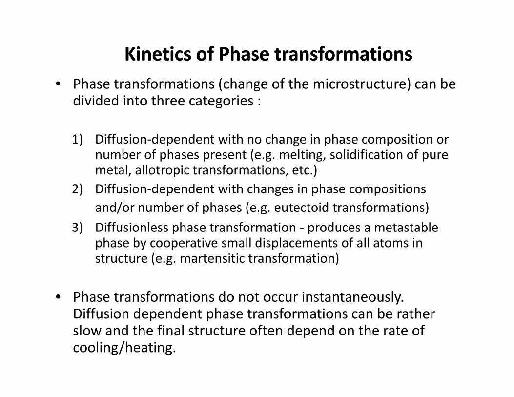
Kinetics of Phase transformationsKinetics of Phase transformations• Phase transformations (change of the microstructure) can be
divided into three categories :
1) Diffusion-dependent with no change in phase composition ornumber of phases present (e.g. melting, solidification of puremetal, allotropic transformations, etc.)
2) Diffusion-dependent with changes in phase compositionsand/or number of phases (e.g. eutectoid transformations)
3) Diffusionless phase transformation - produces a metastablephase by cooperative small displacements of all atoms instructure (e.g. martensitic transformation)
• Phase transformations do not occur instantaneously.Diffusion dependent phase transformations can be ratherslow and the final structure often depend on the rate ofcooling/heating.
• Phase transformations (change of the microstructure) can bedivided into three categories :
1) Diffusion-dependent with no change in phase composition ornumber of phases present (e.g. melting, solidification of puremetal, allotropic transformations, etc.)
2) Diffusion-dependent with changes in phase compositionsand/or number of phases (e.g. eutectoid transformations)
3) Diffusionless phase transformation - produces a metastablephase by cooperative small displacements of all atoms instructure (e.g. martensitic transformation)
• Phase transformations do not occur instantaneously.Diffusion dependent phase transformations can be ratherslow and the final structure often depend on the rate ofcooling/heating.

The Pearlite TransformationThe Pearlite Transformation• Pearlite is a specific mixture of two phases
formed by transforming austenite ofeutectoid composition to ferrite andcementite.
• It is readily recognized by its Brighterappearance and its structure of alternateplates of ferrite and cementite.
• Pearlite is a specific mixture of two phasesformed by transforming austenite ofeutectoid composition to ferrite andcementite.
• It is readily recognized by its Brighterappearance and its structure of alternateplates of ferrite and cementite.Cementite
Ferrite
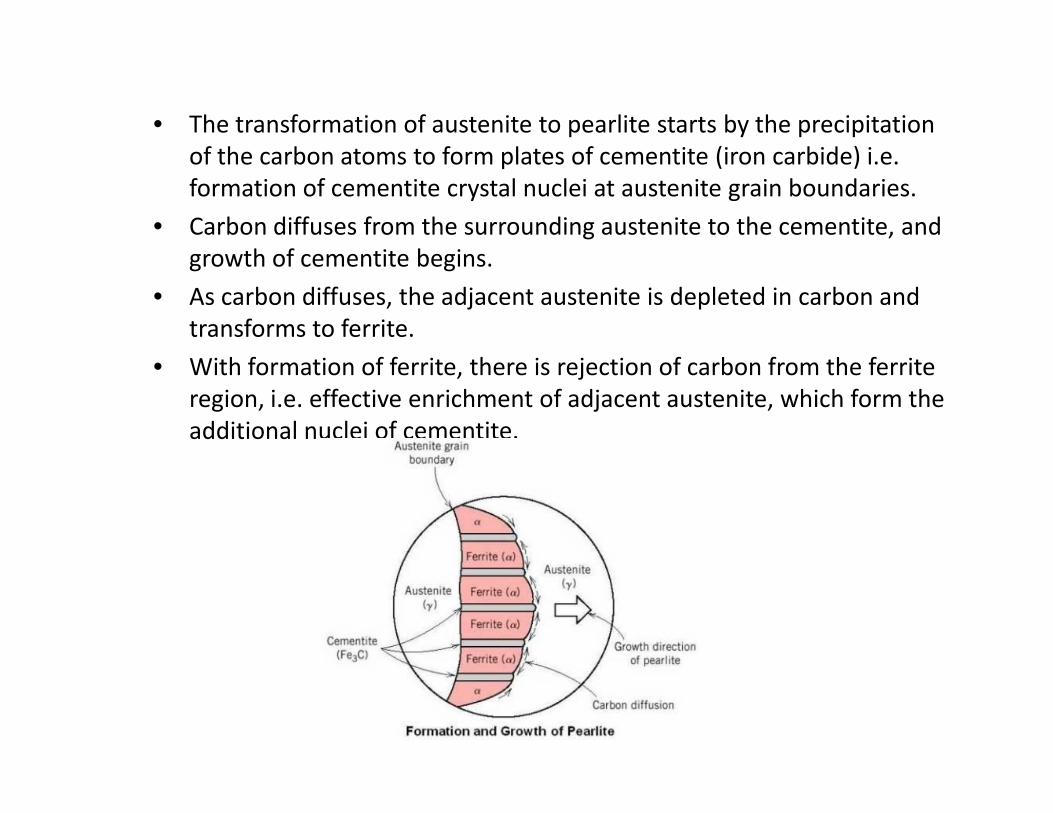
• The transformation of austenite to pearlite starts by the precipitationof the carbon atoms to form plates of cementite (iron carbide) i.e.formation of cementite crystal nuclei at austenite grain boundaries.
• Carbon diffuses from the surrounding austenite to the cementite, andgrowth of cementite begins.
• As carbon diffuses, the adjacent austenite is depleted in carbon andtransforms to ferrite.
• With formation of ferrite, there is rejection of carbon from the ferriteregion, i.e. effective enrichment of adjacent austenite, which form theadditional nuclei of cementite.

• Because of alternate formation of α & Fe3C, Fe3C canonly grow away from the boundary of original austenite.
• Nucleation and growth of α & Fe3C, forms pearlitecolonies .
• These pearlite colonies grow until the entire austenitegrain has been consumed & has become a pearlite nodule.
• Because of alternate formation of α & Fe3C, Fe3C canonly grow away from the boundary of original austenite.
• Nucleation and growth of α & Fe3C, forms pearlitecolonies .
• These pearlite colonies grow until the entire austenitegrain has been consumed & has become a pearlite nodule.
Pearlite colonies

T.T.T. DiagramT.T.T. Diagram• Time –Temperature – Transformation diagram
• It is also called as S – curve, C – curve, Bain’s curve,Isothermal transformation diagram.
• It shows the relationship between temperature andtime taken for a transformation to take place in a metalwhen the transformation is isothermal.
• It is used particularly in the assessment ofdecomposition of austenite in a heat treatable steel.
• Time –Temperature – Transformation diagram
• It is also called as S – curve, C – curve, Bain’s curve,Isothermal transformation diagram.
• It shows the relationship between temperature andtime taken for a transformation to take place in a metalwhen the transformation is isothermal.
• It is used particularly in the assessment ofdecomposition of austenite in a heat treatable steel.

Nucleation of the new phase - formation ofstable small particles (nuclei) of the newphase. Nuclei are often formed at grainboundaries and other defects.
Growth of new phase at the expense of theoriginal phase.
S-shape curve: percent ofmaterial transformed vs.the logarithm of time.

Superheating and SupercoolingSuperheating and Supercooling• During cooling, transformations occur at temperatures
less than predicted by phase diagram: supercooling.
• During heating, transformations occur at temperaturesgreater than predicted by phase diagram: superheating.
• Degree of supercooling/superheating increases with rateof cooling/heating.
• Metastable states can be formed as a result of fasttemperature change. Microstructure is strongly affectedby the rate of cooling.
• During cooling, transformations occur at temperaturesless than predicted by phase diagram: supercooling.
• During heating, transformations occur at temperaturesgreater than predicted by phase diagram: superheating.
• Degree of supercooling/superheating increases with rateof cooling/heating.
• Metastable states can be formed as a result of fasttemperature change. Microstructure is strongly affectedby the rate of cooling.

The effect of time on phase transformationsThe effect of time on phase transformations
eutectoid reaction:γ(0.8 wt% C)↓α (0.022 wt% C)+Fe3C
Let us consider eutectoid reaction
The S-shaped curves are shifted to longertimes at higher T showing that thetransformation is dominated bynucleation (nucleation rate increases withsupercooling) and not by diffusion (whichoccurs faster at higher T)

Isothermal Transformation (or TTT) DiagramsIsothermal Transformation (or TTT) Diagrams(Temperature, Time, and % Transformation)(Temperature, Time, and % Transformation)
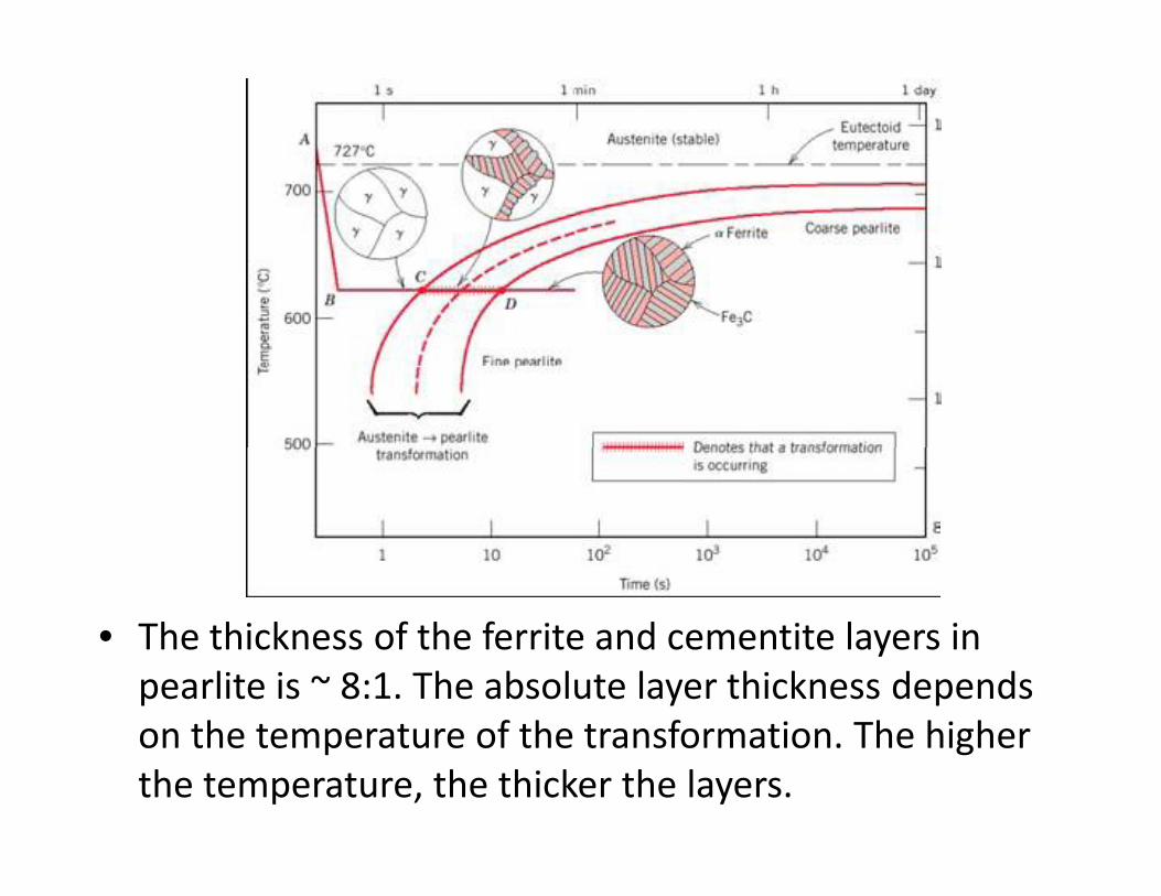
• The thickness of the ferrite and cementite layers inpearlite is ~ 8:1. The absolute layer thickness dependson the temperature of the transformation. The higherthe temperature, the thicker the layers.

TTT DiagramsTTT Diagrams• The family of S-shaped curves at different T are used to construct the
TTT diagrams.• The TTT diagrams are for the isothermal (constant T) transformations
(material is cooled quickly to a given temperature before thetransformation occurs, and then keep it at that temperature).
• At low temperatures, the transformation occurs sooner (it is controlledby the rate of nucleation) and grain growth (that is controlled bydiffusion) is reduced.
• Slow diffusion at low temperatures leads to fine-grained microstructurewith thin-layered structure of pearlite (fine pearlite).
• At higher temperatures, high diffusion rates allow for larger graingrowth and formation of thick layered structure of pearlite (coarsepearlite).
• At compositions other than eutectoid, a proeutectoid phase (ferrite orcementite) coexist with pearlite. Additional curves for proeutectoidtransformation must be included on TTT diagrams.
• The family of S-shaped curves at different T are used to construct theTTT diagrams.
• The TTT diagrams are for the isothermal (constant T) transformations(material is cooled quickly to a given temperature before thetransformation occurs, and then keep it at that temperature).
• At low temperatures, the transformation occurs sooner (it is controlledby the rate of nucleation) and grain growth (that is controlled bydiffusion) is reduced.
• Slow diffusion at low temperatures leads to fine-grained microstructurewith thin-layered structure of pearlite (fine pearlite).
• At higher temperatures, high diffusion rates allow for larger graingrowth and formation of thick layered structure of pearlite (coarsepearlite).
• At compositions other than eutectoid, a proeutectoid phase (ferrite orcementite) coexist with pearlite. Additional curves for proeutectoidtransformation must be included on TTT diagrams.
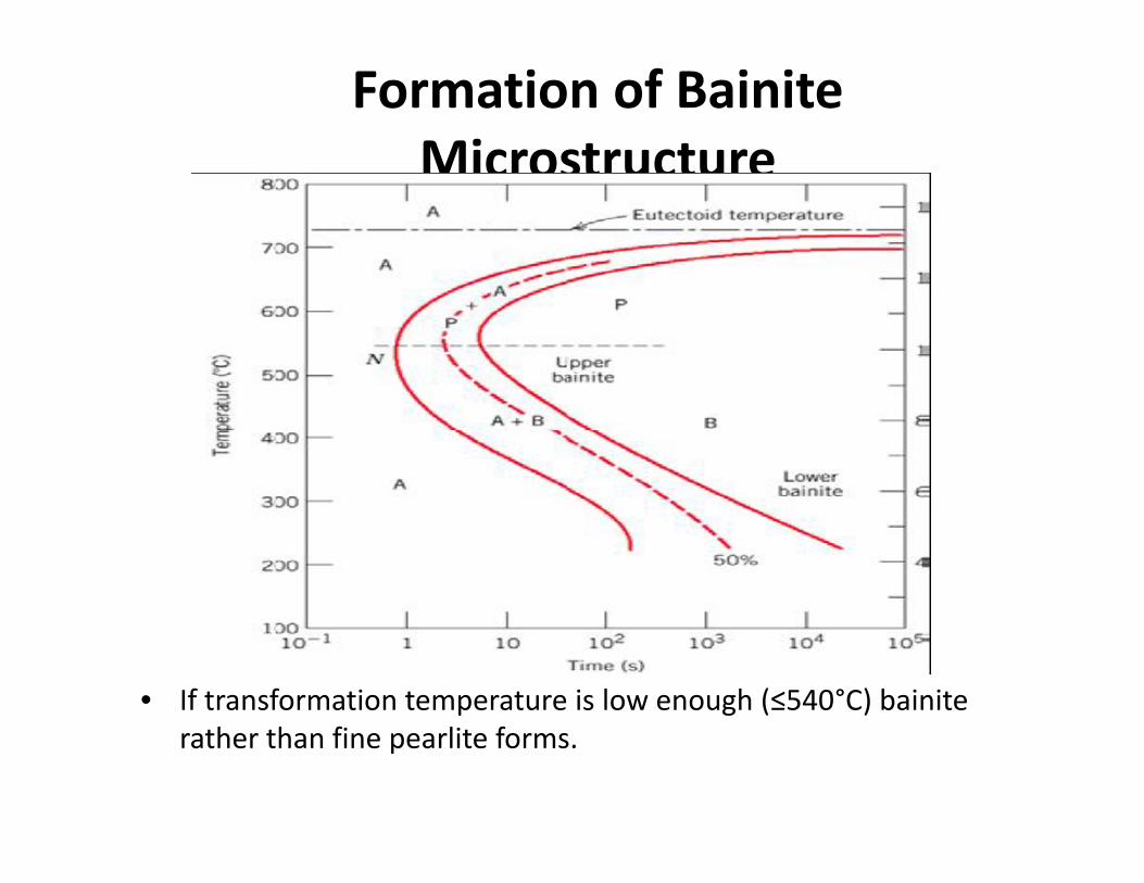
Formation of BainiteMicrostructure
• If transformation temperature is low enough (≤540°C) bainiterather than fine pearlite forms.

Formation of Bainite MicrostructureFormation of Bainite Microstructure• For T ~ 300-540°C, upper bainite consists of needles of ferrite
separated by long cementite particles.• For T ~ 200-300°C, lower bainite consists of thin plates of ferrite
containing very fine rods or blades of cementite.• In the bainite region, transformation rate is controlled by
microstructure growth (diffusion) rather than nucleation. Sincediffusion is slow at low temperatures, this phase has a very fine(microscopic) microstructure.
• For T ~ 300-540°C, upper bainite consists of needles of ferriteseparated by long cementite particles.
• For T ~ 200-300°C, lower bainite consists of thin plates of ferritecontaining very fine rods or blades of cementite.
• In the bainite region, transformation rate is controlled bymicrostructure growth (diffusion) rather than nucleation. Sincediffusion is slow at low temperatures, this phase has a very fine(microscopic) microstructure.

Importance of T.T.T. diagramImportance of T.T.T. diagram• The Fe-C equilibrium diagram shows only the
phases and the resulting microstructurescorresponding to equilibrium conditions.
• So, Fe-C dia. is only used to fix the austenitizingtemperature and to predict the phases thatobtained at a given temperature andcomposition.
• But time with temperature of transformationhad much more influence on the transformationproducts and the properties of steel.
• So the microstructure and properties of steelare depends on cooling rate.
• The Fe-C equilibrium diagram shows only thephases and the resulting microstructurescorresponding to equilibrium conditions.
• So, Fe-C dia. is only used to fix the austenitizingtemperature and to predict the phases thatobtained at a given temperature andcomposition.
• But time with temperature of transformationhad much more influence on the transformationproducts and the properties of steel.
• So the microstructure and properties of steelare depends on cooling rate.

SpheroiditeSpheroidite• Annealing of pearlitic or bainitic microstructures at elevated
temperatures just below eutectoid (e.g. 24 h at 700 C) leads tothe formation of new microstructure – spheroidite - spheres ofcementite in a ferrite matrix.
• Composition or relative amounts of ferrite and cementite are notchanging in this transformation, only shape of the cementiteinclusions is changing.
• Transformation proceeds by C diffusion – needs high T.
• Annealing of pearlitic or bainitic microstructures at elevatedtemperatures just below eutectoid (e.g. 24 h at 700 C) leads tothe formation of new microstructure – spheroidite - spheres ofcementite in a ferrite matrix.
• Composition or relative amounts of ferrite and cementite are notchanging in this transformation, only shape of the cementiteinclusions is changing.
• Transformation proceeds by C diffusion – needs high T.

MartensiteMartensite• Martensite forms when austenite is rapidly cooled (quenched) to room T.• It forms nearly instantaneously when the required low temperature is
reached. The austenite-martensite does not involve diffusion → nothermal activation is needed, this is called an athermal transformation.
• Each atom displaces a small (sub-atomic) distance to transform FCC γ-Fe(austenite) to martensite which has a Body Centered Tetragonal (BCT)unit cell (like BCC, but one unit cell axis is longer than the other two).
• Martensite forms when austenite is rapidly cooled (quenched) to room T.• It forms nearly instantaneously when the required low temperature is
reached. The austenite-martensite does not involve diffusion → nothermal activation is needed, this is called an athermal transformation.
• Each atom displaces a small (sub-atomic) distance to transform FCC γ-Fe(austenite) to martensite which has a Body Centered Tetragonal (BCT)unit cell (like BCC, but one unit cell axis is longer than the other two).

Cont…Cont…• Martensite is metastable - can persist indefinitely at room
temperature, but will transform to equilibrium phases onannealing at an elevated temperature.
• Martensite can coexist with other phases and/ormicrostructures in Fe-C system.
• Since martensite is metastable non-equilibrium phase, itdoes not appear in phase Fe-C phase diagram.
• The martensitic transformation involves the suddenreorientation of C and Fe atoms from the FCC solid solutionof γ-Fe (austenite) to a body-centered tetragonal (BCT) solidsolution (martensite).
• Martensite is metastable - can persist indefinitely at roomtemperature, but will transform to equilibrium phases onannealing at an elevated temperature.
• Martensite can coexist with other phases and/ormicrostructures in Fe-C system.
• Since martensite is metastable non-equilibrium phase, itdoes not appear in phase Fe-C phase diagram.
• The martensitic transformation involves the suddenreorientation of C and Fe atoms from the FCC solid solutionof γ-Fe (austenite) to a body-centered tetragonal (BCT) solidsolution (martensite).

Isothermal Transformation DiagramIron-carbon alloy
with eutectoidcomposition.
A: AusteniteP: PearliteB: BainiteM: Martensite
Iron-carbon alloywith eutectoidcomposition.
A: AusteniteP: PearliteB: BainiteM: Martensite

Other elements (Cr, Ni, Mo, Si andW) may cause significant changesin the positions and shapes of theTTT curves:
Change transition temperature; Shift the nose of the austenite-to-
pearlite transformation to longertimes;
Shift the pearlite and bainite nosesto longer times (decrease criticalcooling rate);
Form a separate bainite nose;
Effect of AddingOther Elements
4340 Steel
Other elements (Cr, Ni, Mo, Si andW) may cause significant changesin the positions and shapes of theTTT curves:
Change transition temperature; Shift the nose of the austenite-to-
pearlite transformation to longertimes;
Shift the pearlite and bainite nosesto longer times (decrease criticalcooling rate);
Form a separate bainite nose;
plaincarbonsteel
nose
Plain carbon steel: primaryalloying element is carbon.

Example : Iron-carbon alloy with
eutectoid composition. Specify the nature of the final
microstructure (% bainite,martensite, pearlite etc) for thealloy that is subjected to thefollowing time–temperaturetreatments:
Alloy begins at 760˚C and hasbeen held long enough toachieve a complete andhomogeneous austeniticstructure.
Treatment (a) Rapidly cool to 350 ˚C Hold for 104 seconds Quench to room temperature
Bainite,100%
Example : Iron-carbon alloy with
eutectoid composition. Specify the nature of the final
microstructure (% bainite,martensite, pearlite etc) for thealloy that is subjected to thefollowing time–temperaturetreatments:
Alloy begins at 760˚C and hasbeen held long enough toachieve a complete andhomogeneous austeniticstructure.
Treatment (a) Rapidly cool to 350 ˚C Hold for 104 seconds Quench to room temperature

Example : Iron-carbon alloy with
eutectoid composition. Specify the nature of the final
microstructure (% bainite,martensite, pearlite etc) for thealloy that is subjected to thefollowing time–temperaturetreatments:
Alloy begins at 760˚C and hasbeen held long enough toachieve a complete andhomogeneous austeniticstructure.
Treatment (b) Rapidly cool to 250 ˚C Hold for 100 seconds Quench to room temperature Martensite,
100%
Example : Iron-carbon alloy with
eutectoid composition. Specify the nature of the final
microstructure (% bainite,martensite, pearlite etc) for thealloy that is subjected to thefollowing time–temperaturetreatments:
Alloy begins at 760˚C and hasbeen held long enough toachieve a complete andhomogeneous austeniticstructure.
Treatment (b) Rapidly cool to 250 ˚C Hold for 100 seconds Quench to room temperature
Austenite,100%

Bainite, 50%
Example : Iron-carbon alloy with
eutectoid composition. Specify the nature of the final
microstructure (% bainite,martensite, pearlite etc) for thealloy that is subjected to thefollowing time–temperaturetreatments:
Alloy begins at 760˚C and hasbeen held long enough toachieve a complete andhomogeneous austeniticstructure.
Treatment (c) Rapidly cool to 650˚C Hold for 20 seconds Rapidly cool to 400˚C Hold for 103 seconds Quench to room temperature
Austenite,100%
Almost 50% Pearlite,50% Austenite
Bainite, 50%
Example : Iron-carbon alloy with
eutectoid composition. Specify the nature of the final
microstructure (% bainite,martensite, pearlite etc) for thealloy that is subjected to thefollowing time–temperaturetreatments:
Alloy begins at 760˚C and hasbeen held long enough toachieve a complete andhomogeneous austeniticstructure.
Treatment (c) Rapidly cool to 650˚C Hold for 20 seconds Rapidly cool to 400˚C Hold for 103 seconds Quench to room temperature
Final:50% Bainite,50% Pearlite

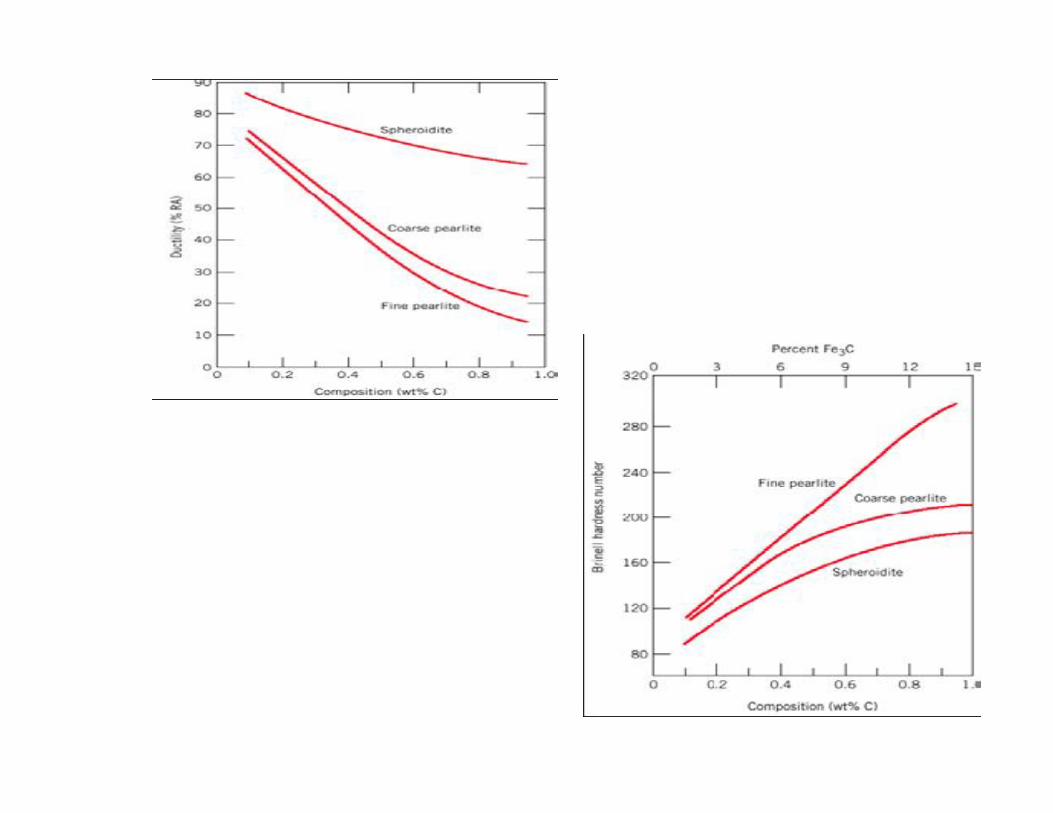
Mechanical Behavior of FeMechanical Behavior of Fe--C AlloysC Alloys• Cementite is harder and more brittle than ferrite - increasing
cementite fraction therefore makes harder, less ductile material.

• Mechanical properties of bainite, pearlite,spheroidite
• Considering microstructure we can predict that– Spheroidite is the softest– Fine pearlite is harder and stronger than coarse
pearlite– Bainite is harder and stronger than pearlite
• Mechanical properties of martensite– Martensite is the hardest, strongest and the most
brittle
Mechanical Behavior of FeMechanical Behavior of Fe--C AlloysC Alloys
• Mechanical properties of bainite, pearlite,spheroidite
• Considering microstructure we can predict that– Spheroidite is the softest– Fine pearlite is harder and stronger than coarse
pearlite– Bainite is harder and stronger than pearlite
• Mechanical properties of martensite– Martensite is the hardest, strongest and the most
brittle

Tempered MartensiteTempered Martensite• Martensite is so brittle that it needs to be modified for practical
applications. This is done by heating it to 250-650 C for some time(tempering) which produces tempered martensite, an extremelyfine-grained and well dispersed cementite grains in a ferritematrix.
• Tempered martensite is less hard/strong as compared to regularmartensite but has enhanced ductility (ferrite phase is ductile).
• Tempered martensite is a microstructure of ferrite and carbideobtained by tempering.
• The resulting microstructure is not lamellar, but it contains dispersedcarbide particles.
• It is softer and much tougher than the metastable martensite.• Mechanical properties depend upon cementite particle size: fewer,
larger particles means less boundary area and softer, more ductilematerial .
• The time require for softening decreases as the tempering temperatureis increased.
• Martensite is so brittle that it needs to be modified for practicalapplications. This is done by heating it to 250-650 C for some time(tempering) which produces tempered martensite, an extremelyfine-grained and well dispersed cementite grains in a ferritematrix.
• Tempered martensite is less hard/strong as compared to regularmartensite but has enhanced ductility (ferrite phase is ductile).
• Tempered martensite is a microstructure of ferrite and carbideobtained by tempering.
• The resulting microstructure is not lamellar, but it contains dispersedcarbide particles.
• It is softer and much tougher than the metastable martensite.• Mechanical properties depend upon cementite particle size: fewer,
larger particles means less boundary area and softer, more ductilematerial .
• The time require for softening decreases as the tempering temperatureis increased.

Higher temperature &time: spheroidite (soft)

(FCC) (BCC) + Fe3Cquench
M (BCT)tempering
slow cooling
Martensite Formation
M (BCT)tempering

Possible Transformations
Stre
ngth
Duc
tility
MartensiteT Martensite
bainitefine pearlite
coarse pearlitespheroidite
General Trends


Temper Brittleness in steelsTemper Brittleness in steels• It is a brittleness resulting from
– holding certain steels within a particular temperature below thetransformation range.
– by cooling slowly through this range.• After being quenched and tempered some alloy steels lose their
impact resistance become brittle, if after tempering, they areslowly cooled or held for longer time in the temperature range600-300 ˚C.
• The brittleness appears at or below room temperature.• Brittleness after tempering is termed as “ Tempered Brittleness”.
• It is a brittleness resulting from– holding certain steels within a particular temperature below the
transformation range.– by cooling slowly through this range.
• After being quenched and tempered some alloy steels lose theirimpact resistance become brittle, if after tempering, they areslowly cooled or held for longer time in the temperature range600-300 ˚C.
• The brittleness appears at or below room temperature.• Brittleness after tempering is termed as “ Tempered Brittleness”.

Critical Cooling RateCritical Cooling Rate
• In Figure the cooling rates A and B indicate two rapid cooling processes.• The end product of both cooling rates will be martensite. Cooling rate B
is known as the Critical Cooling Rate, which is represented by a coolingcurve that is tangent to the nose of the TTT diagram.
• Critical Cooling Rate is defined as the lowest cooling rate whichproduces 100% Martensite.

Importance of CCRImportance of CCR
• Important when hardening the steels. To obtainfully martensitic structure, the cooling rate must bemore than CCR.
• Actually it determines the type of structureobtained on cooling. Slow cooling will producepearlite and higher cooling rate can formmartensite.
• The final properties of the steel will depend uponthe magnitude of the CCR.
Factors Affecting CCRFactors Affecting CCR• Composition of steel: The CCR varies with the
carbon content of steel. It is minimum when C isaround 0.9%.
• Temperature of Hardening: The higher is thehardening temperature, the more uniformbecomes the austenite, the lower is the criticalcooling time, and more will be the critical coolingrate.
• Purity of Steel: The purer is the steel, the lesserwill be the CCR.
• Composition of steel: The CCR varies with thecarbon content of steel. It is minimum when C isaround 0.9%.
• Temperature of Hardening: The higher is thehardening temperature, the more uniformbecomes the austenite, the lower is the criticalcooling time, and more will be the critical coolingrate.
• Purity of Steel: The purer is the steel, the lesserwill be the CCR.

Continuous CoolingContinuous CoolingTransformation DiagramsTransformation Diagrams
Isothermal heat treatments arenot the most practical due torapidly cooling and constantmaintenance at an elevatedtemperature.
Most heat treatments for steelsinvolve the continuous coolingof a specimen to roomtemperature.
TTT diagram (dotted curve) ismodified for a CCT diagram(solid curve).
For continuous cooling, the timerequired for a reaction to beginand end is delayed.
The isothermal curves areshifted to longer times andlower temperatures.

The image part with relationship ID rId3 was not found in the file.
Moderately rapid and slowcooling curves are superimposedon a continuous coolingtransformation diagram of aeutectoid iron-carbon alloy.
The transformation starts after atime period corresponding to theintersection of the cooling curvewith the beginning reactioncurve and ends upon crossing thecompletion transformation curve.
Normally bainite does not formwhen an alloy is continuouslycooled to room temperature;austenite transforms to pearlitebefore bainite has becomepossible.
The austenite-pearlite region (A---B) terminates just below thenose. Continued cooling (belowMstart) of austenite will formmartensite.

For continuous cooling of asteel alloy there exists a criticalquenching rate that representsthe minimum rate ofquenching that will produce atotally martensitic structure.
This curve will just miss thenose where pearlitetransformation begins
For continuous cooling of asteel alloy there exists a criticalquenching rate that representsthe minimum rate ofquenching that will produce atotally martensitic structure.
This curve will just miss thenose where pearlitetransformation begins
α-ferrite - solid solution of C in BCC Fe• Stable form of iron at room temperature.• The maximum solubility of C is 0.022 wt%• Transforms to FCC g-austenite at 912 C
γ-austenite - solid solution of C in FCC Fe• The maximum solubility of C is 2.14 wt %.• Transforms to BCC δ-ferrite at 1395 C• Is not stable below the eutectic temperature
(727 C) unless cooled rapidly (Chapter 10) δ-ferrite solid solution of C in BCC Fe
• The same structure as a-ferrite• Stable only at high T, above 1394 C• Melts at 1538 C
Fe3C (iron carbide or cementite)• This intermetallic compound is metastable, it remains as a
compound indefinitely at room T, but decomposes (veryslowly, within several years) into α-Fe and C (graphite) at 650- 700 C
Phases in Fe–Fe3C Phase Diagram α-ferrite - solid solution of C in BCC Fe
• Stable form of iron at room temperature.• The maximum solubility of C is 0.022 wt%• Transforms to FCC g-austenite at 912 C
γ-austenite - solid solution of C in FCC Fe• The maximum solubility of C is 2.14 wt %.• Transforms to BCC δ-ferrite at 1395 C• Is not stable below the eutectic temperature
(727 C) unless cooled rapidly (Chapter 10) δ-ferrite solid solution of C in BCC Fe
• The same structure as a-ferrite• Stable only at high T, above 1394 C• Melts at 1538 C
Fe3C (iron carbide or cementite)• This intermetallic compound is metastable, it remains as a
compound indefinitely at room T, but decomposes (veryslowly, within several years) into α-Fe and C (graphite) at 650- 700 C