Embed Size (px)
Citation preview

průmyslová elektronikaRadaR level meteRs GRlm –70 "miRanda"
GRLM-70-dat-1.8
Variants of sensors
The GRLM® radar level meters are compact measurement devices including an transmitter of microwave pulses, central processor unit and display module. The electronics transmits very short electrical pulses (0.5 ns), which are linked to a one-wire transmission line (measuring electrode). Measuring electrode can be created of rod or rope. The pulse propagates along the electrode in the form of electromagnetic wave toward the level surface, where it is partly reflected and the reflected component is returned to the receiving module of the electronics. The electronics measures the time of flight of electromagnetic wave and the instant distance to the surface level is calculated. According to the level height, the level meter output is set and the measured value is displayed on the display.
Radar level meters are resistant against changes in the atmosphere (pressure, tem-perature, dust, steam) and to changes in medium parameters (change in dielectric constant, conductivity).
GRLM –70_–00 without electrode, the electrode is made by customer (only variant 10 or 30) and connected to the electrode junction by M8 thread.
GRLM –70_–10 Uncoated stainless steel rod electrode, for level measurement liquids and bulk solidmaterials (water, water solutions, emulsion, oils, diesel, flour, sand, granulates, etc.).Maximum electrode length 8 m.
GRLM –70_–11 Fully coated stainless steel rod electrode (PFA Teflon®), for level measurement of aggressive liquids and very pure liquids. Maximum electrode length 2 m.
GRLM –70_–12 Fully coated stainless steel rod electrode (FEP Teflon®), for level measurement of aggressive liquids and drinks. Maximum electrode length 2 m.
GRLM –70_–20 Uncoated stainless steel rod electrode with reference tube, for accurate level measurement of liquids in cramped spaces. Maximum electrode length 3 m.
GRLM –70_–30 Uncoated stainless steel rope electrode and weight, for level measurement of liquids and bulk solid materials (water, grains, sand, flour, cement, etc.) in higher silos, vessels, reservoirs.Maximum electrode length 40 m.
GRLM –70_–32 Fully coated stainless steel rope electrode (FEP Teflon®) and coated weight (PTFE), for level measurement of aggressive liquids and very pure liquids. Maximum electrode length 12 m.
GRLM –70_–33 Uncoated stainless steel rope electrode with anchorage, for level measurement of bulk solid materials (grains, flour, cement, etc.) in higher silos, vessels. Maximum electrode length 40 m.
radar leVel meters with guided waVe (principle tdr)• Suited to continuous level mesurement of various liquid,
bulk solids, mush and pasty materials.
• Quick view measured values on the display
• Universaluse,directmountingintohoppers,silos, tanks, sumps etc.
• Variantswithstainlesssteelrodorropeelectrode
• Measuringrangeupto40m
• Possibilityofusinginexplosiveareas(versionXi,XiT),
orinflammabledustareas(Xd,XdT)
• Currentoutput(4...20mA),HART® protocol

GRLM-70-dat-2.8
dimensional drawings
GRLM–70_–10(11,12) GRLM–70_–20
GRLM–70_–30(33,34,35) HightemperaturevariantGRLM–70_T
GRLM–70_–32
Anchoring eye for variant GRLM-70_-33(35)
GRLM–70_–00
variant GRLM-70 with protective conductor
GRLM–70_–34 Coatedstainlesssteelropeelectrode(Polyamid)anduncoatedweight,afor level measurement of liquids and adhesive bulk solids (flour, cement, etc.). aaaMaximum electrode length 40 m.
GRLM–70_–35 Coatedstainlesssteelropeelectrode(Polyamid)withuncoatedanchorage, for level measurement of adhesive bulk solids (flour, cement, etc.). aMaximum electrode length 40 m.
GRLM-70-dat-3.8
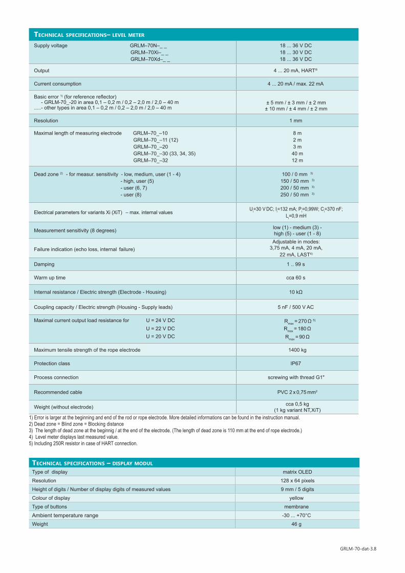
technical specifications – display modul
Type of display matrix OLED
Resolution 128 x 64 pixels
Height of digits / Number of display digits of measured values 9 mm / 5 digits
Colour of display yellow
Type of buttons membrane
Ambient temperature range -30 ... +70°C
Weight 46 g
technical specifications– leVel meter
Supply voltage GRLM–70N–_ _ GRLM–70Xi–_ _ GRLM–70Xd–_ _
18 ... 36 V DC18 ... 30 V DC18 ... 36 V DC
Output 4 ... 20 mA, HART®
Current consumption 4 ... 20 mA / max. 22 mA
Basic error 1) (for reference reflector) - GRLM-70_-20 in area 0,1 – 0,2 m / 0,2 – 2,0 m / 2,0 – 40 m.....- other types in area 0,1 – 0,2 m / 0,2 – 2,0 m / 2,0 – 40 m
± 5 mm / ± 3 mm / ± 2 mm ± 10 mm / ± 4 mm / ± 2 mm
Resolution 1 mm
Maximal length of measuring electrode GRLM–70_–10 GRLM–70_–11 (12) GRLM–70_–20 GRLM–70_–30 (33, 34, 35) GRLM–70_–32
8 m2 m3 m
40 m12 m
Dead zone 2) - for measur. sensitivity - low, medium, user (1 - 4) - high, user (5) - user (6, 7) - user (8)
100 / 0 mm 3)
150 / 50 mm 3)
200 / 50 mm 3)
250 / 50 mm 3)
Electrical parameters for variants Xi (XiT) – max. internal valuesUi=30 V DC; Ii=132 mA; Pi=0,99W; Ci=370 nF;
Li=0,9 mH
Measurement sensitivity (8 degrees) low (1) - medium (3) -high (5) - user (1 - 8)
Failure indication (echo loss, internal failure)Adjustable in modes:
3,75 mA, 4 mA, 20 mA, 22 mA, LAST4)
Damping 1 .. 99 s
Warm up time cca 60 s
Internal resistance / Electric strength (Electrode - Housing) 10 kΩ
Coupling capacity / Electric strength (Housing - Supply leads) 5 nF / 500 V AC
Maximal current output load resistance for U = 24 V DC U = 22 V DC
U = 20 V DC
Rmax = 270 Ω 5)
Rmax = 180 ΩRmax = 90 Ω
Maximum tensile strength of the rope electrode 1400 kg
Protection class IP67
Process connection screwing with thread G1"
Recommended cable PVC 2 x 0,75 mm2
Weight (without electrode) cca 0,5 kg (1 kg variant NT,XiT)
1) Error is larger at the beginning and end of the rod or rope electrode. More detailed informations can be found in the instruction manual.2) Dead zone = Blind zone = Blocking distance3) The length of dead zone at the beginnig / at the end of the electrode. (The length of dead zone is 110 mm at the end of rope electrode.)4) Level meter displays last measured value.5) Including 250R resistor in case of HART connection.

GRLM-70-dat-4.8
used materials
Sensor part Variants Standard material
Lid All types aluminium with powder coating
Glass All types polycarbonate
Body All types aluminium with powder coating
Housing with thread All types St. Steel W. Nr. 1.4571 (AISI 316 Ti)
ElectrodeGRLM-70_-10(11,20)GRLM-70_-12GRLM-70_-30(32,33,34,35)
St. Steel W. Nr. 1.4571 (AISI 316 Ti)St. Steel W. Nr. 1.4301 (AISI 304)
St. Steel W. Nr. 1.4404 (AISI 316 L )
Electrode coating
GRLM-70_-11GRLM-70_-12GRLM-70_-32GRLM-70_-34, 35
PFAFEPFEPPA
Reference tube GRLM-70_-20 St. Steel W. Nr. 1.4301 (AISI 304)
Weight GRLM-70_-30 St. Steel W. Nr. 1.4301 (AISI 304)
Weight coating GRLM-70_-32 PTFE
Anchorage GRLM-70_-33 St. Steel W. Nr. 1.4301 (AISI 304)
Display module All types plastic material POM
deVice classification (according to EN 60079-10-1 and EN 60079-10-2)GRLM–70N Performance for non-explosive areas
GRLM–70NT High temperature performance for non-Ex areas (max. 200°C)
GRLM–70Xi(XiT)Performance for explosive areas (gases or vapour)
II 1/2 G Ex ia IIB T6 Ga/Gb with ISSU 1) electrode part zone 0, housing zone 1
GRLM–70Xd(XdT) Performance for flammable dust areas II 1 D Ex ta IIIC T85°C…T300°C Da (current), II 1 D Ex ta IIIC T100°C…T300°C Da(Modbus), whole level meter zone20
1) Intrinsically safe supply unit (for example: Dinel IRU–420).
temperature and pressure resistiVity (performance N, Xi)
Variants / Performance temperature tp temperature tm temperature ta
Max. operation pressure for temp. tp
to 30°C to 85°CGRLM–70_–10(20) -40°C ... +85°C -40°C ... +300°C -30°C ... +70°C 15 MPa 10 MPaGRlM –70_–11(12) -40°C ... +85°C -40°C ... +200°C -30°C ... +70°C 4 MPa 2,5 MPaGRLM–70_–30(33) -40°C ... +85°C -40°C ... +200°C -30°C ... +70°C 15 MPa 10 MPaGRLM–70_–32 -40°C ... +85°C -40°C ... +130°C -30°C ... +70°C 1 MPa 0,5 MPaGRLM–70_–34(35) -40°C ... +85°C -40°C ... +95°C -30°C ... +70°C 15 MPa 10 MPa
temperature resistiVity (performance NT, XiT)
Variants / Performance temperature tp temperature tm temperature ta
GRLM–70_T–10(20) -40°C ... +200°C -40°C ... +300°C -30°C ... +70°CGRlM –70_T–11(12) -40°C ... +200°C -40°C ... +200°C -30°C ... +70°CGRLM–70_T–30(33) -40°C ... +130°C -40°C ... +200°C -30°C ... +70°CGRLM–70_T–32 -40°C ... +130°C -40°C ... +130°C -30°C ... +70°CGRLM–70_T–34(35) -40°C ... +130°C -40°C ... +95°C -30°C ... +70°C
Note: For correct function of the level meter must not be exceeded any of the temperature range (tp, tm or ta).
pressure resistiVity (performance NT, XiT)
Variants / PerformanceMax. operation pressure for temp. tp
to 30°C to 85°C to 130°C to 160°C to 200°CGRLM–70_T–10(20) 15 MPa 10 MPa 3 MPa 2 MPa 1 MPaGRlM –70_T–11(12) 4 MPa 2,5 MPa 2 MPa 1,5 MPa 0,3 MPaGRLM–70_T–30(33) 15 MPa 10 MPa 3 MPa - -GRLM–70_T–32 1 MPa 0,5 MPa 0,1 MPa - -
tp –Temperature in process connection place
tm – Medium operating temperature
ta –Ambient temperature range (on housing)

GRLM-70-dat-5.8
maximal temperatures for performance xi(xit) category 1/2gtemp. class temperature tp temperature tm temperature ta
T5 -40°C ... +90°C -40°C ... +98°C -30°C ... +70°C
T4 -40°C ... +125°C -40°C ... +133°C -30°C ... +70°C
T3 -40°C ... +190°C -40°C ... +198°C -30°C ... +70°C
T2 -40°C ... +200°C -40°C ... +298°C -30°C ... +70°C
T1 -40°C ... +200°C -40°C ... +300°C -30°C ... +70°C
The maximum allowable temperature of the medium, process connection and ambient temperature depends in GRLM-70Xi (XiT) at the desired temperature class (see tab. Maximum temperatures for the performance Xi (XiT) category 1/2G and tab.). The temperature value can not be exceeded, because the hot surface of the device could cause ignition of an explosive or flammable atmosphere. At the same time can not exceed the maximum temperature for the different variants of the electrodes (Table of temperature durability).
installation
Install the level meter into the upper lid of the tank or reservoir using a weldingflangeor fastering nut. The min. distance to install the level meter into a lid or a ceiling of a tank from the metal tank wall is 300 mm and from the non-metal tank wall is 500 mm (except GRLM-70_-20).
If installed in an open channel (sumps, reservoirs, etc.), install the level meter as closest as you can to the maximum level expected.
Rope electrode level meter must untangle and then can be inserted into the tank.
In case any visible defects are discovered, the manufacturer or reseller of this equipment must be contacted immediately.
installation and recommendations
We recommend to keep the specified distances from the tank wall. Otherwise, the level meter install as far as possible from the walls, to the middle between the wall and the vertical inlet.
The minimum distance of measuring electrodes from the bottom of the tank is not specified. In case that could occur touching of the electrodes with the bottom of the tank, it is necessary that the electrode was fixedly attached to the tank bottom (the connection may be conductive or non-conductive).
For correct measurement it is important to avoid installation in the high neck. For short neck are recommended dimensio-nal paremeters:
valid for:valid for:
all types
E = m + t + k E = m + t + z
all types
exceptGRLM-70_-20
If you can not eliminate all inter-ference, which could affect the measurement of level, it is reco-mmended to use the procedure "TEACHING" (see Instruction manual). This procedure sets the level meter to mode, which supp-resses false reflections.
E – The length of rope electrodet – Measuring rangem – Dead zone on the beginning of electrodek – Dead zone on the end of electrodez – The lengt of weight (110 mm) d – The distance from the tank wall (see Table)
a ≤ bb ≥ 50 mma – Neck heightb – Neck width
type of wall d(without ref. tube)
d(with ref. tube)
metal ≥ 300 mm any distance
non-metal ≥ 500 mm any distance
deVice surface temperature for performance xd(xdt) category 1d part of level meter device surface
temperatureelectrodeGRLM-70_-_-_-IGRLM-70_-_-_-M
medium temp. tm +5°Cmedium temp. tm +10°C
housing, electronic partGRLM-70_-_-_-I
GRLM-70_-_-_-M
temperature tp +15°Ctemperature ta +15°Ctemperature tp +30°Ctemperature ta +30°C

GRLM-70-dat-6.8
It is necessary to install the level meter so that the bin level cannot interfere with the dead zone when filled up to the maximum or deplete to the minimum. If the measured level interferes with the dead zone, the level meter will not work properly. The size of the dead zone is affected by the set measurement sensitivity. The minimum distances to the medium (dead zones) are presented in the tables below.
valid for:
all types
Nedoporučujeme instalovat hladinoměr v, nebo nad mís-tem plnění. Může docházet k ovlivnění měření vtékajícím médiem a nikoliv k měření hladiny materiálu.
Wrong CorreCt
The end of the socket or the welding flange must not have an extension into the tank.
valid for:
all types
exceptGRLM-70_-20
Wrong
For level meter installation in non-conductive tanks it is necessary to use a metal sheet (dia-metral greater than 200 mm) beneath the pro-cess fitting when screwing it in. Make sure that the plate has direct contact with the process fitting.
a < b
For installation of the level meter on a con-crete roof the diameter b of the hole must be greater than the thickness a of the concrete.
If the thickness a of the concrete is greater than the diameter b of the hole, install the level meter in a recess .
valid for:
all types
exceptGRLM-70_-20
valid for:
GRLM-70_-30, 32, 33
valid for:
all types
measurement sensitivity m k
(rod electrode)k
(rope electrode)low, medium, user (1 - 4) 100 mm 0 mm 110 mm
high, user (5) 150 mm 50 mm 110 mm
user (6, 7) 200 mm 50 mm 110 mm
user (8) 250 mm 50 mm 110 mm

GRLM-70-dat-7.8
s ... Radius of protective zone along the electrode level meter.
s = 300 mm
It is determined protective zone along the electrode of radius 300 mm. The level meter is recommended to install the tank so that the items placed inside the tank (ladders, various partitions, mixers, etc.) does not intervene into the protective zone.
If still these objects intervene into the protective zone of the level meter, it is necessary to create a map of false reflections by activating the "TEACHING". In case of installed mixers, it is necessary to position the mixers near the level meter (turning the mixer blade to the proximity of the electrode). Items inside the tank must not be from the electrode distance of less than 100 mm, because a interference of electromagnetic field is very strong in this zone and "TEACHING" mode can not be used.
CorreCt Wrong
valid for:
all types
exceptGRLM-70_-20
n ... Minimum distance of objects from the electrode
n = 100 mm
For the type of level meter GRLM-70_-20 electromagnetic guided wave propagates inside the reference tube. This wave is not affected by the am-bient environment. So for this type of radar is not intended protective zone around the electrodes and the level meter can be used for measurements in cramped spaces.
valid for:
GRLM-70_-20
It is suitable to run the cable under a cable bushing (obliquely down in slack) to pre-vent penetration of humidity. Then the rain and condensing water can flow off freely.The cable bushing and connector have to be sufficiently tightened to prevent pen-etration of humidity.
valid for:
GRLM-70_-00
The level meter must not be installed in places with direct solar radiation and must be protected against weather effects.If the installation in places with direct solar radiation is inevitable, it is necessary to mount a shielding cover above the level meter.
valid for:
all types
Type of level meter without electrode is supplied without an electrode. It is therefore necessa-ry to a customer to mount his own made measuring electrode. The diameter of the electrode must be between 8-10 mm. For a conne-ction it is necessary that on the electrode is made M8 thread. The connection procedure is given in Instruction manual.
For type GRLM-70_-00 manufacturer is not responsible for defects which are caused by the connected measuring electrode!
If you can not eliminate all interference, which could affect the measurement of level, it is recommended to use the procedure "TEACHING" (see Instruction Manual). This procedure sets the level meter to mode, which suppresses false reflections.
valid for:
all types

GRLM-70-dat-8.8
Always disconnect the supply voltage before connecting the level meter!
The power supply can be a stabilized voltage supply unit of 18 ... 36V DC (18 ÷ 30 V DC for version Xi(XiT)), that is included in evaluation or display unit.
In case of strong electromagnetic interference (EMI), parallel supply cable with power lines, or when the cable length exceeds 30 m, we recommend you to use a shielded cable.
Connection diagram of the level meter
Internal view of terminal block
Display unit connector
Terminal block
Metal clip
The radar level meter is designed to be connected to supply unit or to controller through a cable with the outer diameter of 6 ÷ 8 mm (recommended cross-section of cores 0.5-0.75 mm2) by means of bolted clips placed under display module. Connect the plus pole (+U) to the terminal "+", the minus pole to 0V to the terminal "-" and the shielding to the terminal " " (only for shielded cables).
electrical connection
E = m + t + z valid for:
GRLM-70_-30, 32, 33
For installation of the level meter with rope electrode into deep tanks and silos the length of the electrode must be selected so that the weight will be below the minimum measured level. It must be ensured that the rope electrode could not touch the vessel wall caused by the motion of the medium. Take care does not exceed the maximum tensile load of the rope electrode. The value of the max. tensile strength is specified in chapter "Technical specifications". High loads can break the rope.
For installation of the level meter with rope electrode with anchorage into deep tanks and silos it is recommended to place the anchorage clo-ser to axis of the silo than is the position of level meter. This mounting will lower the This installation will reduce the side forces of the me-dia on the rope electrode.
In case of anchoring we re-commend to preload the rope electrode by tension force of about 100 N.
valid for:
GRLM-70_-33
leVel meter setting
Set the level meter using 3 buttons placed on the display module. All settings are accessible in the GRLM-70 set-up mode access. For detailed information please read at the instructions manual.
button
• Set-up mode access• Confirmation of selected item in the menu• Saving of set-up data
button• Move in the menu• Change of values
button• Cancelling of carried out changes • Shift one level up
* Slow flashing while the reflected signal (echo) is received from the measured level.
E – The length of rope electrodet – Measuring rangem – Dead zone on the beginning of electrodez – The lengt of weight (110 mm)d – The distance from the tank wall (min. 300 mm)
ESC OK
www.dinel.cz
Ultrasonic Level Meter ULM-70
ESC OK
1745T E mm
ESC OK
www.dinel.cz
Ultrasonic Level Meter ULM-70
ESC OK
1745T E mm
Displayof measured values
Set-up elements
Teachingmode activation
UnitsEcho receiving*
Lock of level meter
The type of level meter GRLM-70_-__-_-_-_-L is supplied without a display module DM-70. To set the level meter it is required to join the display module. Once set, the display modu-le can be disconnected and the level meter can measure without him.
verz
e 9/
2015
GRLM-70-dat-9.8
Dinel, s.r.o.U Tescomy 249760 01 Zlín, Czech Republic
Phone: Fax:
+420 577 002 003+420 577 002 007
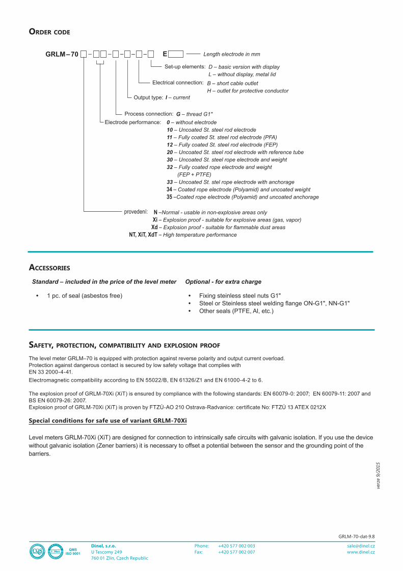
accessories
Standard – included in the price of the level meter Optional - for extra charge
• 1 pc. of seal (asbestos free) • Fixing steinless steel nuts G1" • Steel or Steinless steel welding flange ON-G1", NN-G1"• Other seals (PTFE, Al, etc.)
safety, protection, compatibility and explosion proof
The level meter GRLM–70 is equipped with protection against reverse polarity and output current overload.Protection against dangerous contact is secured by low safety voltage that complies withEN 33 2000-4-41.Electromagnetic compatibility according to EN 55022/B, EN 61326/Z1 and EN 61000-4-2 to 6.
The explosion proof of GRLM-70Xi (XiT) is ensured by compliance with the following standards: EN 60079-0: 2007; EN 60079-11: 2007 and BS EN 60079-26: 2007. Explosion proof of GRLM-70Xi (XiT) is proven by FTZÚ-AO 210 Ostrava-Radvanice: certificate No: FTZÚ 13 ATEX 0212X
Special conditions for safe use of variant GRLM-70Xi
Level meters GRLM-70Xi (XiT) are designed for connection to intrinsically safe circuits with galvanic isolation. If you use the device without galvanic isolation (Zener barriers) it is necessary to offset a potential between the sensor and the grounding point of the barriers.
order code
provedení:
Electrode performance: 0 – without electrode10 – Uncoated St. steel rod electrode11 – Fully coated St. steel rod electrode (PFA)12 – Fully coated St. steel rod electrode (FEP)20 – Uncoated St. steel rod electrode with reference tube30 – Uncoated St. steel rope electrode and weight32 – Fully coated rope electrode and weight
(FEP + PTFE)33 – Uncoated St. stel rope electrode with anchorage34 – Coated rope electrode (Polyamid) and uncoated weight35 –Coated rope electrode (Polyamid) and uncoated anchorage
N –Normal - usable in non-explosive areas only Xi – Explosion proof - suitable for explosive areas (gas, vapor) Xd – Explosion proof - suitable for flammable dust areas NT, XiT, XdT – High temperature performance
GRLM – 70 –
Output type: I – current
– –
Process connection: G – thread G1"
E Length electrode in mm– –
Electrical connection: B – short cable outletH – outlet for protective conductor
Set-up elements: D – basic version with displayL – without display, metal lid