Embed Size (px)
Citation preview

j Unclassi i-SCCU54-1 C..ASSIrICATION OF rmis PAGE014 1
REPORT DOCUMENTATION PAGEI .,OAT SECURITY CLASSIFICATION I. RISTRICTIVE MARKINGS
2s, SECUR I T Y CLASSIFICATION AUTHORITY 3. OISTRIBUTIONIAVAILABILITY OF REPORT
2b DE CLASS$FICATI.JNIOOWN
GRAOINO SCHEDULE
6 PREFORMINO ORG'ANIZATION REPORT NUMBERISI 5. MONITORING ORGANIZATION REPORT NUMuERIS)
2196w NAME OF PERFORMING ORGANIZATION Gb. OPFICE SYMBOL 7a. NAME OP MONITORING ORGANIZATIONCrystal Growth and Materials fi applicabte
Testing Associates
6C. AoRESS (City, State end P Code) 7b. AOORESS (City., Sate and ZIP Codei6918 Lamont DriveLanham, MD 20706
&. NAME OP FUNOINO/SPONSORING " b. OFFICE SYMBOL 9. PROCUREMENT INSTRUMENT IOENTIFICATION NUMBERORGANIZATION (it appliceble)Naval Research Laboratory N00014-86:-C-2180
&:.' AODRESS WIly. Store and ZIP Code) 10. SOURCE OF FUNOING NOS.Disbursing Officer PRORAM PROJECT TASK WORK UNIT
Attn: Code 1332 ILEMINT NO. NO. NO. NO.
Naval Research Laboratory, Wash., DC 20375-I I TITLE 'i.niud. Security CIu ,ticaion) 5000Ceramics
12, PERSONAL AUTHOR(S)
R.J. Arsenault, N. Louat, M. Duesbery, R. Spann, S. LawrenceI3& TYPE 07 REPORT 13b. TIME COVEREo 14. DATE OF REPORT (Yr., Mo., Deyl) 15. PAGE COUNT
Final I FOM 8-29-86 To2 - 2 9 - 8 8 1988 Nov. 3 551 SUPPLEMENTARY NOTATION
17 COSATI COOES 18. SUBJECT TERMS IConlInu° on re~uran If nece"O°- and idsntity by block number)
FIELO GROUP SUB. OR.
19. ABST t CT ICon IO'u on rovrii if nectooary and idln tlly by block number)
The intrinsic task of this contract was to perform research to obtain fundamentalinsights into the mechanical and electrical properties of ceramics.
The specific items in the statement of work are necessary steps that had to becompleted innorder to reach the goal of obtaining fundamental insights.
In this final report, flue topics will be discussed in detail:
o Fracture of ceramics
0 Computer modelling of ceramics containing ordered voids',
0 Interaction of dislocations with planar free surfaces
o Application of superconducting ceramics to microwave substrates
* High Tc superconducting ceramic oxides . -
20 OISTRIBUTION/AVAILABILITY OP ABSTRACT I1, ABSTRACT SECUITY ;LASSIFICATION
UNCLASSIFIED/UNLIMITIO 0 SAME AS RPT. 0 OTIC USERS d
22, NAME OF RESPONSIBLE INOIVIOUAL j221. TELEPH"ONI NUMBE R22c. OFFICE SYMBOL
Richard J. Arsenault 3 0 1-454- 4 0 75
DO FORM 1473,83 APR IOITION OF i JAN 73 IS OBSOLETE, "nelann4f.rdSECURITY CLASSIFICATION OF THS PAGE

IFI
Report No. 219
CERAMICS
Dr. R.J. ArsenaultDirectorCrystal Growth and Materials Testing Associates6918 Lamont DriveLanham, Maryland 20706
Project Scientists
Dr. Ma DuesberyDr. S. LawrenceDr. N. LouatMr. J. Spann
3 November 1988
Final Report for Contract No. N00014-86-C-2180
Disbursing OfficeATTN: Code 1332NAVAL RESEARCH LABORATORY Accesio, ForWashington, DC 20375-5000
NTIS CgA&,DTIC Ttr EU i*i-f t 'f ed
K) By*
Dist I
S[
4-,,,1i:i-hl iill

TABLE OF CONTENTS
Page
Summary .................................................... 1
Fracture of Ceramics .......................................... 2
Computer Modelling of Ceramics Containing OrderedVoids .................................................... 9
On the Interactions of Dislocations with Planar FreeSurfaces ................................................. 15
Application- of Superconducting Ceramics to MicrowaveSubstrates .................................................. 30
Research and Development of High Tc SuperconductingCeramic Oxides Having Potential Applications inElectromagnetic Equipment and Components ................. 50
I
T'td

1
I SUMMARY
* p The intrinsic task of contract N00014-86-C-2180 was to per-
, form research to obtain fundamental insights into the mechanical
and electrical properties of ceramics.
The specific items in the statement of work are necessary
steps that had to be completed in order to reach the goal of
obtaining fundamental insights.
In this final report five topics will be discussed in detail
* Fracture of ceramics-
* Computer modelling of ceramics containing ordered voids
* Interaction of dislocations with planar free surfaces
* Application of superconducting ceramics to microwave
substrates-
* High Tc superconducting ceramic oxides having potential
applications in electromagnetic equipment and components
* Ii
, i iamli~im []il a

It.
1 2
Fracture in Ceramics
,i N. Louat
IMeasurements of KIC in ceramics are commonly made using channelled
I specimens in a double cantilever configuration. One difficulty with this
method is that the moment necessary for initial crack motion exceeds that
j which is necessary when it is fully developed and which can be related to
- the specific properties of the material.
One method of overcoming this difficulty is to modify the specimen geo-
metry so that within certain bounds crack propagation becomes increasingly
difficult with increasing crack length. The modification considered here is
, to make -the specimen wedge-shaped in the sense that the channel increases
linearly in thickness t, from an initial value to, distance x from the free end
in the range o : x 5 L and is constant and equal to tm for x > L. In order
that this procedure be efficacious it is necessary to ascertain the values of L
and of t /t such that is certain that the value of the moment M necessarym 0for the initiation if fracture is insufficient for propagation in the region x
1 L.
As a point of departure we suppose that the stress necessary for crack
finitiation at the specimen edge to be that found by experiment in simple bend
tests and to have the value, aT. We have then to compare this with that
developed at the same place when moments ±M associated with the double
cantilever configuration are applied. Having fixed MT as the moment
necessary for initiation we have then to determine the specimen bevelling
necessary so that MT < Mp. where M P is the moment necessary for crack
I propagation in the parallel sided double cantilever configuration.

I 3Now, the stresses developed near the top of the specimen are sensitive to
the manner of application of the bending moments. We suppose this is
I achieved by the application of loads distributed as shown schematically below
in Fig. I
I
1 2h X
_ I • "
Fig. 1. Schematic load distribution
We suppose that these loads are the same on both faces, to lie in the
range o < x '5 a and to be distributed according to some function f(x) and
that, in order these forces develop only a moment,
j f (x)dx = 0
As first approximation we treat the determination of the resultant stresses
as a two-dimensional problem in elasticity theory. Here we require that
normal and shear stresses vanish over the end surface and take on prescribed
values on the top and bottom. Accordingly, we seek a solution of the bi-
harmonic equation64 640 64
[ ~_ - 2 - +(16x4 6x26y 2 6y4

I1 4
where (p represents the Airy stress function. In these terms we may write:I62 62 62 cy 3 (2)
* Now (1) allows for four disposable constants and at least in the case where
solutions are available by assuming that the variables are separable we are
then able only to specify normal and shear stresses on top and bottom
surfaces. Because it is free, normal and shear stresses are to vanish on the
edge surface. The solutions envisaged do not In general allow this. How-
ever, by adding a dummy section to the specimen so as to have symmetry
about the end surface we can eliminate the shear stresses. Proceeding to the
solution of- this problem we shall see that while the stresses normal to the
edge surface do not vanish they are small and that the error in neglecting
them is likewise small.
In these terms the general solution of (1) is
O m -cos mirx f C cos h miry +p C2 sin h m__Y
%- Ycos hm _y f ,sinbh j''. -.3, , ' '47 * J "
_ cos m~2rx .~
I-

5
and using the relations (2) we- find:
C, sinha + ah coshah (4)a sinhah + 2ah
C2 C.3 = O0;
28 a sinh a (5)C4 = - sinh2ah + 2ah
a = mr/I
Substituting for C, and C4 from (4) and (5) into (3), we find
=2 B (ah coshah- sinh+ah) coshay - ay sinhay sinhac }axx= sin 2ah + 2ah co1
(6)
= f2 (ah coshah + sinhah) coshay - sinhay sinhac }oaOxy= sinh 2ah + 2ah
(7)
xy = -B ah coshac sinhay - ay coshay sinh ac csa-y sinh 2ah +. 2ah cosax (8)
Reference to (7) and (8) shows that as required
a XY = o, ayy = -B cosh ; y = ±h.
This result allows that consder~aions-of a. number of solutions such as to
match the required value of a on y = ±h. Thus, we consideri YY

Z BM cosax.f(y)m=1
where
B = f(x) cos dx (9)Bm Y -I
-a
Then from (7) the required stress a uM a yy atx=Oy=O is
M - m ah coshah + sinhahaM = -BM sinh 2ah + 2ah (10)
This is not the stress which appears at the end of the actual specimen.
There, the surface is free. This requires an additional constraint: normal
stresses are to vanish (shear stresses vanish already). The vanishing of
these stresses involves a displacement of the surface involved. Now dis-
placements which affect ax, also affect a yy and in the same way. This is
fortunate here because a xx at x = O, y 0 is from (6)S -
Bm ah coshah - sinhahsinh 2ah + 2ah
This is a positive quantity while a> is negative. Consequently, surface~YY
adjustments which reduce a xx increase a . Thus, a as given reoresents
an underestimate of the stress actually occurring.
Thus., MC > M,
ir

i ,
7
where M C is the moment calculated on this basis as necessary to produce the
stress for.crack initiation. Thus, in determining a M which exceeds MC wep
also satisfy
Mp> M
which is what is required.
It then remains to specify f(x). This can be done in a number of ways.
Having due regard to the method of attachment between specimen and lever
arms. it seems appropriate to take full cognizance of the effect of the soeci-
men bevelling. Thus, the stresses appearing in the loading arms of thickness
a when bent under the action of moments M are
Mx - M (2x-a)
where X is the distance from the center of inertia of a loading arm and I is
the second moment of area about that center. Then taking specimen thick-
ness at a distance x from its end as:.
t=t o + (t -t) x/L
The stresses in the specimen are
M (2x - a) aL2-T Lto+ x(tm - to)
I

II
I Thus (9) becomes
Bm MaL (2x -a) Mwrxd
=MaL I sin miwa aL car. MIrB fcl mir (B+A) - ci mirrBff RF _ TF 2T T T
L
I ~+ sin rnirB (si mirr (B+A) - si rrurB (1
with si (x) = sin t dtI x
I and ciWx= Y + Inx +Jxcs dtI io t
I Substitution of this value in (10) gives a final expression for the stresses at
the center of the edge of the specimen.
j Unfortunately, these series are intractable to analytic summation but they
have been readily evaluated numerically by Dr. Duesbery for suitable values
of the various parameters. -These results show that a particular value of
a m can be achieved over a range of values of M. This facility allows a
check of the authenticity of a measurement of the M necessary for fracture.
I Thus, the value obtained must lead to the appearance of a stress a M whichu exceeds the fracture stress as measured in a simple bend test on the same
material.
U

1 9I
COMPUTER MODELLING OF CERAMICS CONTAINING ORDERED VOIDS
M. Duesbery
I. INTRODUCTION
The object of this research was to investigate the fracture
I properties of lead zirconate titanate (PZT) ceramic.
For many of the mechanical characteristics of ceramic compo-
sites, analytic theoretical solutions of the field equations are
not obtaimable and numerical methods must be used. A reasonable
approah. tQ computer simulation can be achieved by adapting
I standard molecular dynamics techniques(1 ) using "particles"
containing one or more crystal grains in place of molecules and
I an empirical form fitted to known mechanical and structural
properties.for the particle-particle interaction(2 ).
In the linear limit, this particle dynamic (PD) method has
been shown( 3 ) to be formally equivalent to the finite element
(FE) method used widely for engineering application. However,
I the PD method has several significant advantages over the FE
method for the problem at hand.
(a) Nonlinearities (such as are encountered in the fracture
fprocess, for example) are more easily handled using PD methods.(b) Interactions and constraints additional to the basic
1cohesive potential are easily incorporated into the PD Hamilto-nian formulation. For example, grain boundary energy anistropy
can be simulated by superimposing an orientation-dependent modu-
lation on the cohesive term; inhomogeneities and second phases
can be incorporated with similar ease.I

II
10
I.(c) The PD method does not require matrix inversion and is
consequently more efficient for very large models.
II. SIMULATIONS OF STRESS DISTRIBUTIONS
Mechanical failure of ceramics usually occurs at fabrication-
I linduced surface flaw5 which can amplify the applied stress to the
failure level. There are at least two aspects of the stress
distribution in ceramics containing void arrays which are rele-
J vant to the mechanical' performance-of PZT transducers, both of
which must be evaluated by comparison with void-free material.
The first of these is the maximum internal enhancement of an
applied stress, which if very large, can lead to intrinsic fail-
I ure, i.e. failure independent of flaws. The second factor, which
governs. the probability .of failure at flaws, is the integrated
magnitude of the enhancement on exposed stressed surfaces. For
i optimum mechanical performance both factors should be minimized.
Internal stress distributions have been calculated for two-
I dimensional models containing rectangular voids with a variety of
i sizes and array geometries and~deformed within the linear elastic
limit to a fixed deflection by three-point bending. The results
suggest that the expected linear superposition of single-void
effects is supplemented by cooperative effects due to the regu-
I larity of the void lattice.
The modifications induced in the stress field by an isolated
void are twofold. Firstly, the stress distribution is changed to
conform to the -boundary conditions that there be no normal
stresses at the end surfaces of the void. Secondly, the stressesI

I11
Iin the neighborhood of the void are increased to maintain field
equilibrium over the decreased cross-sectional area. There are
also stress concentrations at the void corners which are probably
due to the sharpness of the corners.
,I Typical stress distributions when an ordered array of voids
is present similarly reflect the void boundary conditions by
showing regions of depleted stress in the intervoid regions
I parallel to the principal tensile stress. Stress concentrations
in the uninterrupted tensile fibers are present, due to stress
redistribution required for equilibrium. The stress concentra-
tions at the void corners are significantly larger than for
isolated voids. It is suspected that this is due to the regular
arrangement of voids which. causes ..the. model. to. resemble a two-
component system consisting of alternate layers of matrix and
matrix-void composite with different effective elastic stiff-
nesses.
- Th, magnitude of the stress concentrations at the void corn-
ers in the 2D models depends strongly on the dimensions of the
voids and the array parameters. For example, for voids which are
f extremely narrow in the principal stress direction, the stress
concentrations at the void corners can reach a factor of two
I larger than the maximum stress encountered in the reference
void-free specimen. It has been found empirically that the
maximum internal stress shows a strong correlation with the
i square of the ratio of the intervoid dimensions parallel and
normal to the principal stress. Therefore, it is possible to

12Iengineer void arrays which have only minor internal stress
enhancements.
A special case occurs when the void array intersects a
stressed surface. The stress concentrations at the void corners
I are similar to those encountered for internal void arrays but the
stressed surface, the usual source of ceramic failure, is nearly
completely unloaded which means that the surface flaws have been
j effectively deactivated.
In summary, our two-dimensional modelling has shown that both
J I of the stress distribution factors affecting transducer perfor-
mance can be influenced significantly by choice of void sizes and
I array dimensions. The internal stress enhancement cannot be
removed, but can be minimized. The integrated-surface.. stresses,
on the other hand, can be reduced substantially. Preliminary
work on three-dimensional simulations suggests that the effects
are less extreme than in two dimensions, i.e. the enhancements
and depletions are not as pronounced.
III. SIMULATIONS OF FRACTURE
Another factor which influences the mechanical performance of
ceramic transducers is the fracture toughness. In a homogeneous
continuum when a crack has been nucleated, propagation can conti-
nue unchecked because the crack tip fields, which by definition
meet the fracture criteria, are invariant to translation. In a
crystalline solid, small modifications are necessary to this
general principle because- of the discrete structure. However, in
a strongly inhomogeneous material, such as a ceramic containing
i1

13Ian array of voids, the process of crack propagation is largely
divorced. from that of crack nucleation. In practical terms, this
means that crack. nucleation, although necessary, is not a suffi-
cient condition for fracture failure. It is necessary also that
n the crack be able to move through the whole sample.
We have modelled failure by fracture for many of the void
array configurations considered in Section II, considering both
Jflaw-free models and models containing a controlled flaw. Novel
fracture processes have been observed which have improved our
f understanding of the fracture-mediating properties of void
arrays.
I For flaw-free models it has been found that fracture always
begins at the location of the largest tensile stress. This
position in most cases is at a void corner adjacent to the ten-
sile surface or at the tensile surface immediately below a void.
In the first case, the crack moves from the void corner to the
f surface and is effectively blunted; in the second case, motion is
from surface to void with the same blunting. In both cases the
crack has been arrested and further propagation proceeds from
f void to void, but only at an increased applied stress. Only when
the void separation in the direction parallel to the principal
stress is very large does crack propagation proceed through the
matrix without arrest at voids.
The preference for crack propagation to proceed by this void
["unzipping" mechanism has been demonstrated further by simula-
tions in models with a controlled flaw located at the center of

iI14
1the tensile surface. The flaw is simulated by breaking a bond
between two surface particles, thereby creating an extrinsic
stress concentration. The stress at the tip of the flaw is
enhanced to a level typically 15-20% greater than the most highly
I stressed void corners, but crack nucleation still occurs prefer-
entially at the void corners and proceeds by the same unzipping
mechanism.
In summary, fracture in two-dimensional models containing
void arrays is observed to proceed preferentially by a void
f unzipping mechanism with crack arrest and renucleation at higher
applied stress at each stage. Crack propagation between voids is
strongly inhibited by the low level of stored elastic energy in
the inter-void regions. These phenomena combine for suitable
void array geometries to provide an intrinsic means for increas-
ing fracture toughness of ceramics.
I References
S1. M.S. Duesbery and M. Kahn, submitted to J. Amer. Ceram. Soc.
2. W.G. Hoover, "Molecular Dynamics," Lecture Notes in Physics,Springer-Verlag, NY, 1986.
3. W.T. Ashurst and W.G. Hoover, "Microscopic Fracture Studiesin the Two-Dimensional Triangular Lattice," Phys. Rev. B14
I (1976) 1465.
I

ON THE INTERACTIONS OF DISLOCATIONS WITHI PLANAR FREE SURFACES
I N.P. Louat and K. Sadananda*
Abstract
Fourier synthesis is employed to obtain solutions to the coupled singu-
lar integrations which accordinp to the method of dislocation continua
I represent equilibrium.
I The cases of screw and edge dislocations totally contained within
parallel planar surfaces are considered first. An initial extension of the
I method to problems in three dimensions is then made and exemplified by
the treatment of an edge dislocation which lies normal to a free surface.
Introduction
2The stress fields of dislocations which lie parallel to infinite free
surfaces have been evaluated in a number of ways (i,2,3 4). Among these
is the representation of the conditions for equilibrium of a single surface
i in terms of singular integral equations. This method is here further
developed so as to deal with cases where more than one face surface can
be involved and where the dislocation is not parallel to a single surface.
To illustrate the method and recover known results we begin with the
simple case of a screw dislocation in a thin plate.
I 1. Screw Dislocation Totally Within a Thin Plate
[ We consider a elastically isotropic plate of thickness h, with a screw
dislocation located at a distance y from the lower surface. The stresses
• Employee, Material Science and Technology Div., NRLit[

1 18at a point of coordinates r), referred to this dislocation are:
pb _ _ (1)
I .
J where p is the shear modulas and b the Burgers vector.
We now suppose that the stress-engendered surface displacements can
I be represented by the distribution of a dislocation continuum in each
j surface. We designate the distributions of lower and upper surfaces as
a (x) and P (x), respectively.
For this situation, the stresses a must vanish at the free surfaces.
We represent these conditions in terms of the dislocation continua through
the singular integral equations:
x M dt t-x
a (t) - + t) dt; (2)
I x2+yz t-x (t-X)2 + h2
x dt t-- 3 N+ - + I a (+) dr. (3)I x2 + (h-Y)2 -00 t-x -C (t-x)2 + h2
Towards the solution of these simultaneous equations we suppose:
I a (x) A (k) cos kx dk; (4).! 0
I . . l ll I I - I II III I I I II

I (x)= 9 (k) cos kx dk. (5)
1 10and note thatI
x k- e-ky sin kx dk.
Then substituting in (2) and (3) we have
j -ky sin kx dk = JA(k) dk Jcos kt
0 -00
+ B(k) dk cos kt dt
o J (t-x)+ h2
-r - 0 JA (k) sin kx dk -Tr JB (k) e-kh sin kx dk
io o
and similarlyI
ek (h-y) sin kx dk = -Tr B (k) sin kx dk -7r fA(k) e-kh sin kx dk
tWhence,
e-ky = -7rA - 7rBe-kh
* Ie k (h-y) -kh[
,,tl ,=m m m mmmnu I I

Solving these simultaneous linear equations we have:
I sinhk(h-y) I sinh kyi A = - -- ; B = -"V sinh kh r sinh kh
Then using (4) and (5),
i sin ry/hS(x) = - - 1
2h cosrx/h .+ cos ry/h
I sin vry/ha x =--
2h cos 7rx/h - cos ry/h
The stresses rzy developed by these arrays are at the point q, (reference
lower surface):
J a(x) +9Wdx(x-y)2+ 2 (x-y)2-(h-2
si +
!r x-2r h cos h ! -cos X __+2 CshL o27O hJ h x'+ ~ h "h
(x-y) 2 (h-) dx (6)
This is readily evaluated by considering the contour integral
[ ( 1 dz0 z-- ;-syU+i vI osz r/h-cos-rry/h z- -ic

19
with the contour consisting of the planes v = o and v = h, Joined at infinity
by vertical lines. This contour is to be transversed In the positive (anti-
I clockwise) direction so that the two infinite integrals are transversed in
opposite directions and so have opposite signs. This is compensated for by
* Ithe fact that cosh 7r (u+i h)/h = cosh 7ru/h. In turn, the real parts of
1/(z-rq-i ) are the required algebraic functions of (6). Using Cauchy's
residue theorem the required integral is thus the real part of
Pb I '- -" 27ri .
- 27ri coshr r-+ij/h -cos ry/hj
pb sin h s-in 5-- zrlx *sinIfl}
2h os h- MCos C os-'+- - 2 -sinh
This agrees with the result from a single plane when h -+ co.
I2. Edge Dislocation Totally Within a Thin Plate
Proceeding as for the case of the screw dislocation we consider a plate
of thickness h, with an edge dislocation with its Burgers- vector., b,
parallel to the surfaces located at a distance y from the lower surface.
The stresses at a point of coordinates x, q referred to this dislocation are:
y (x2 +y2) 2
I,,4.

20
~.(x 2_yZ) (8)
Y yy y(x2+Y2) 2
I
(3x 2 +y 2 )
(xZ+y2)(
where 0 = pb/2r(I-j,).
Proceeding as before we now suppose that the surface displacements
engendered by these stresses can be represented by two distributions of
dislocation continua in each surface. The displacement vectors of each
pair are mutually orthogonal, being either parallel or perpendicular to the
surfaces. We designate the distributions of the lower surface as f(t) and
g(t) and those of the .upper. surface by h(t).and .k(t)-.-The displacement
vectors of f(t) and h(t) are chosen to be parallel to the surfaces.
With these definitions and using (7), (8) and (9) we formulate the
equations of equilibrium: lower surface (shear stresses vanish);
(x2-y dt (-) hI px =A f (t)- + A NO (t-x) dt
(x 2+y 2)2 J t-x _0[(t-x) 2 + h2]2
+ _c. h 2 - (t-X) 2
A k(t) h dtoi /2 (t -- 1212
where A = PX/2Tr(i-v) and X represents the magnitude of a unit
dislocation; upper surface (shear stresses vanish);
I
.. ... -- m d I ,, re it a - -,

21
(x2-y 2) = - f dt (t-X) 2 -h
2
(XZ+Y 2) 2 FCf t-x _J ( (t-x) 2+h~j
3h2-i-(t-x)2
+ -A Fk(t) (t-x) (h2+ (t-X) 212 d
Lower surface (normal stresses vanish);
(X2-y2) CO dt OD (t-x)2 - hy=-A Jg(t) - + Ah Ih(t) 2+22dt
(X2+ y2) 2 I-D t-x 3-0 (tX
+Ar (t) (t-x) 32+t- 2dt. (12)
Upper surface (normal stresses vanish);
q(h-y) 22--A Jk(t) - - Ah J0f(t) M 4 W12d tIX2+~o 1(t-) 2 +h 120t-
OD 3 h2 + (t -XJ Ig W)(t- X) I tX2h)2dt (13)-(00 2 h~l
Having regard to the known parity of the functions involved, we now
suppose that:

I
1I 22
f (t) JF(k) coskt dk; 2
10
h{t) = jH(k cos kt dk;o
git) = JG(k) csnkt dk;-0
gt) = KG(k) sinkt dk;
k0t) K KWE sin kt dk.
"0
Then taking (as appropriate), the sine and cosine transforms of the left-
hand-side of equations (4-7), these become
J(1 -ky) e-kysinkx dx =" J F(k) cos kt dk
1(Ot-xIM
+ (t-x) (t-x) +hz]dt H(k) coskt dk
[~h(t-X) 2 + )
+ hj h+t)J dt JK(k) sinkt dk- 0
I OO co e-khHT JF(k) sinkx dk + 7r (i -kh) ekH(k) sinkx dk
"0 0
+ irh sinkx dk
t "0

I
1 23
and so
I I ky)e-ky -F(k) + ir(I-kh)e-khH(k) + 7rhke-khK(k)
i In like manner (5), (6) and (7) become
I It -k(h-y))e - k (h-y) = H (k) + (I -kh) e-khF (k) - khe-kh W(k)II -ky -kh .- kh
_ - kye 7- G(k) + (I +kh) e K(k)..- kbe-hH (k)
Ik(h-y)ek(h- y ) = -Kk) + (1 + kh) e-khG(k) + kh e-khF(k)
Thus, the system of simultaneous integral- is reduced. to. four. linear
algebraic equation in the Fourier transforms. The solution of these
equations is straightforward, but tedious and easily subject to error. In
practice, the use of algebraic computer programs is recommended. The
solutions found by hand are:
ir(c 2-I) 2 F(k) = -E (c2 - i -a+J-Jc 2 -ac 2) -DC (i +2a-c 2-d+c 2 d);
Tr(c 2-t) 2G(k) = E(j-c 2 J-c 2 a-a) + DC(dc 2 -d+2a);
r(c2-i) 2H(k) = -Ec(Jc 2 -c 2 -J+1 +2a) -D (-de' +c 2 - J -a + d - ac 2)
Tr(c 2 -I)K(k) = -Ec(Jc 2 -J+2a) -D(d-c 2d-ac2 -a).
where: E = eky; 3 = k(h-y); D = ek(h-y); c = ekh; a =kh and d =ky.
Thus, for example:

I
I
(ekh - )ekh(sinh k(y-h) ky cosh ky- - 4khe2kh sinh ky
£17 F2,(e zkh_1)?
Similar expressions are obtained for G, H and K.
The stresses at a point xo, yo are then given by integration. For
example, the contribution to the shear stresses Oxy from the distribution
G are seen to be:[ y o -(X -X o 0 1 , 00°
oxy(G) = yoo -Xo dx " 0(k) sinkx dk (15)xy I-CO (y4+ (.-X)d 2 12 1
where
g(x) k) sin kx dk
Changing the order of integration we have
rxy (G) = Yo (k) dk . 2 sin k(u+x) du
YofG k) f (yQ-+u2 )
dk (Y'2 2)2 cos ku sin kx du
- Yo G(k) sin kx k e-ky dk (16)
IThe integrals resulting from substitutions such as that necessary for
G(k) in (16) do not appear to be effectable in terms of known functions.
However, numerical integration can be expected to be a simple matter.
25
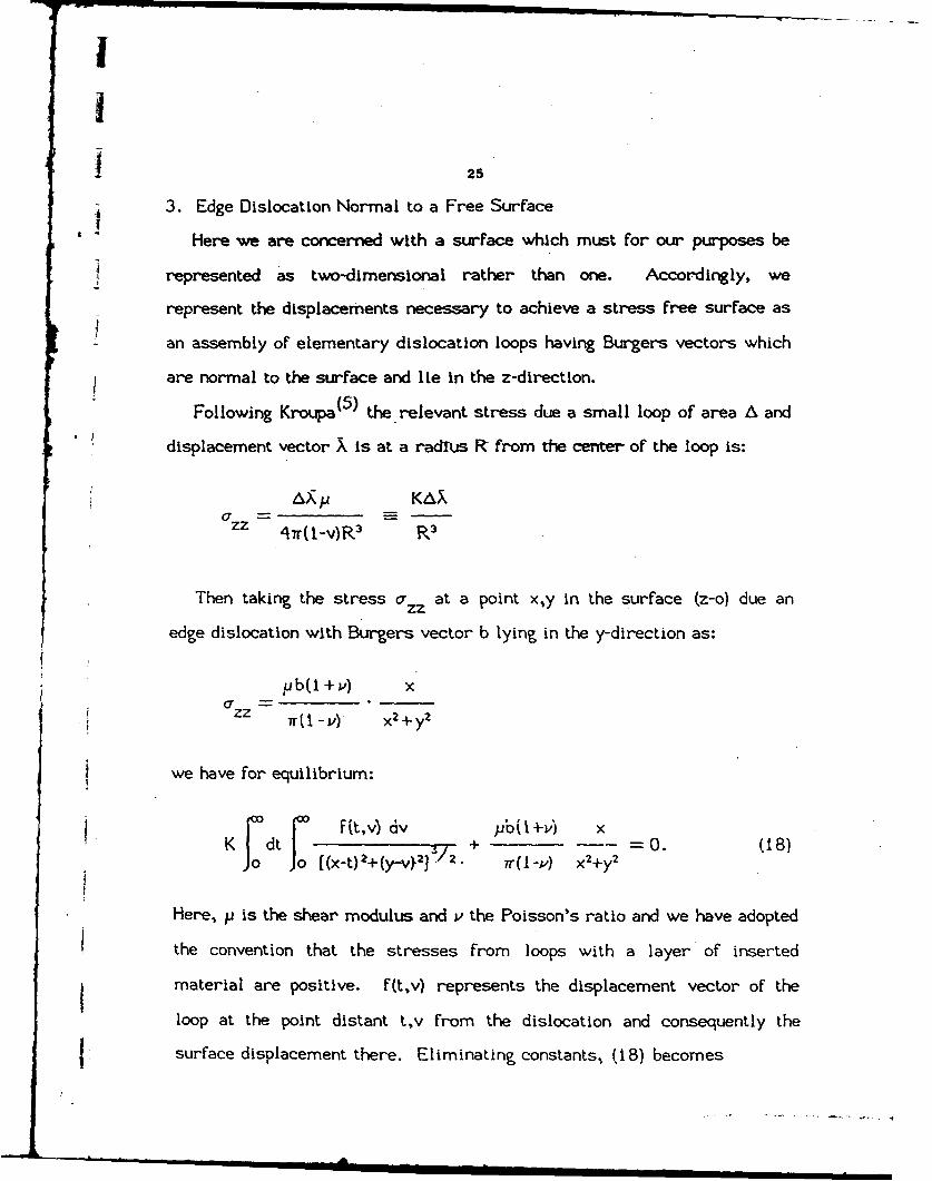
3. Edge Dislocation Normal to a Free Surface
Here we are concerned with a surface which must for our purposes be
represented as two-dimensional rather than one. Accordingly, we
represent the displacements necessary to achieve a stress free surface as
an assembly of elementary dislocation loops having Burgers vectors which
are normal to the surface and lie in the z-direction.
Following Kroupa (5 ) the relevant stress due a small loop of area A and
displacement vector X is at a radius R from the center of the loop is:
AxPj KA X
zz 47r(1-v)R 3 R 3
Then taking the stress ozz at a point x,y in the surface (z-o) due an
edge dislocation with Burgers vector b lying in the y-direction as:
ub(I +v) xi ZZ --
Tr ( 7M -v) x +y
we have for equilibrium:
,~ ~ ( t, V) dv Ub( i +I) dt0 8
K dt (xt)+(y-v}]. + 0. (18)r2r(I-Y) x2+y 2
Here, p is the shear modulus and v the Poisson's ratio and we have adopted
the convention that the stresses from loops with a layer of inserted
material are positive. f(t,v) represents the displacement vector of the
loop at the point distant t,v from the dislocation and consequently the
fsurface displacement there. Eliminating constants, (18) becomes
surface'

I
26
r0"d I c f (t~v) dv pbU +j/) x
J o ((x-t)2+(y-v)l ] + 7r(I-V) x2+y2
We now proceed somewhat as before but using double Fourier transforms
so that we can write
x 8b(i-i-i) Icfocok4b(lI+v) - = sin ks cos sy dk ds.x2+y Y1 r .. 6 k2+sl
and on introducing the Fourier transform F(k~s) and changing the order of
integrations
F(ks)dk ds sin kt cos sv
0 0 dk0 [d(x dt dv
4b(I +v)J sin kx cos sy dk ds
00 o k2+s 2
Substituting: x-t = u; y-v = w, the first expression reduces to
F(ks) sin kx cos sy dk ds i o(To ro(u2+w2)/2
Now, It may be observed that the second set of integrals are not well
behaved. This difficulty may be handled following Hadamard(6) and taking
[ the finite part. Thus, we write
1'

27
sdw d cos swr(ku2w)/ duo0 (uJ2+w;)
2 d- - Ko (stu)u du
where K Is a complete elliptic function of the first kind. Thus,
cos SW dw K , (su) cos ku+ ku du F (+2)/2 = -2s -- du
= 2 fodk Fs KI(su) sinku du
0
= Tr =__k _ 7r(s2+k2)i
Substituting in Eq. 19, we have..
r J0 F(ks) (s2 + k2)2 sinkx cossy dk ds
= 4b(I+v) f sin kx cos sy dk ds
4b kso that F (k,s) - (I+ v) -+ /
Tr (k2+S) 12
t I !

1 28
and
f (t,v) ff F(ks) slnkt cossv dk ds
I 4b(I +Pj~)ki r{kZ~ /zsin kt cos sv dk ds
4b(t+vj) t K6 (W~co. sv ds
IT T
so that
tf (t v) =b U t+ V)f~t~v~(t+v2)
Thus, the displacement at a distance r from the dislocation is sinu-
soidal with rotation about the dislocation. It is a maximum at the
position of the inserted or (missing) plane of atoms.
Now, Kroupa has given all the stresses a xx, oxy, aryy due to an infin-
itisimal loop as a function G of the coordinates x, y and z so that the
Istresses arising from the free surface are immediately expressible in
terms of integrals of the form
I F~f,v) G (x-t,y-v,z) dt dv
Development of this approach to deal with straight dislocations skew
I to the surface appears realizable but Kroupa's expressions appear so

: 29
complicated that the task of dealing with two parallel surfaces is, to say
, the least, daunting.
SUMMARY..
i It has been shown that certain problems involving the displacements of
free surfaces in the presence of dislocations can be expressed in terms of
* coupled integral equations and that they can be reduced to ordinary simul-
taneous algebraic equations in the Fourier transforms of the unknown
functions. Three problems are detailed: (1) a screw and (2) an edge
dislocation totally within a thin plate and (3) an edge dislocation normal to
a free surface.
REFERENCES
I. A.K. Head, Froc Phys. Soc., 66B, (1953) 801.
2. N.P. Louat, Nature 196 (1962) 1081.
3. F.R.N. Nabarro and C.J. Kostlan, J. Appl. Phys. 49 (1978) 5445.
, 4. W. Moss and J. Hoover, J. Appl. Phys. 49 (1978) 5449.
5. F. Kroupa, Phil. Mag. 7 (1962) 783.
6. J. Hadamard, Lectures on Cauchy's Problem, Dover Publ., 139.

I
1 30
APPLICATION OF SUPERCONUCTING CERAMIC S TO
, MICROWAVE SUBSTRATES
I R. Spanm and M. Kahn*
ABSTRACT
The following is a status report on work directed towards the attain-
I ment of superconducting, high performance microstrip transmission lines,
using YBaiCu3O7 _x (YBC) material.
Section I describes efforts at qualifying the composition and prepara-
tion process of superconducting powder. This was characterized in super-
conductive discs by X-ray analysis, resistance-temperature behavior and
microstructure. In Section II, preparation parameters of adherent, graded
layers of superconducting YBC material on alumina are discussed.
I. INTRODUCTION
It has been shown that localized voids can significantly enhance the
signal propagation rates in microstrip transmission lines(I), without
affecting the desired thermal properties of the substrates. This also opens
javenues to reducing problems such as crosstalk between closely spaced
conductor paths, as well as making possible tailored delay lines where
paths of physically different lengths can have the same propagation delay.
Superconductors repulse external magnetic fields. The electromagnetic
coupling between two adjacent microstrip transmission lines is therefore
eliminated and crosstalk is further reduced. The absence of series
resistance in the strip line can also be expected to further minimize the
[ * Employee of the Material Science and Technology Division, NRL

I
3 31.pulse dispersion. Preparation parameters of superconductive film strip
lines-on ceramics containing voids as well as the modelling of their
behavior are to be addressed.
_I. BACKGROUND AND OBJECTIVES
The demonstrated increases in pulse propagation rates of microstrip
transmission lines on ceramics with patterned voids were attained by a
topical reduction of the dielectric constant of the substrate, implementedthrough the application of fugitive ink and tape technology. Hybrid
technology was then applied to print the conductors.
It is the primary aim of the present work to investigate the materials,
processes and technology needed to make these conductors superconductive,
so as to further enhance the high speed pulse performance of these micro-
circuits.
III. FILM DEPOSITION APPROACHES
The application of superconductive films to ceramic substrates con-
taining void patterns was evaluated by using two approaches:
i. Submicron thick films result from - the pyrolytic decomposition of
organometallic solutions. Three to five such layers can result in films 2
pm thick. Conductors, 0.5 mm wide, made from such films could carry
only about i mA before superconductivity is lost.. The preparation of much
thicker films from organometallic material does not appear practical at
this time.
2. Films, 20 to 80 pm thick, can easily be made by using conventional
I -"thick film" technology. "Conventionally" prepared ceramic powders were
1!N

32
used for this and deposition via the thick film process was investigated in
depth._..
SECTION I SELECTION AND CHARACTERIZATION OF MATERIALS
SYSTEM
As a first step, It is necessary to qualify the chemical composition and
determine the proper physical parameters of a ceramic powder that will
give a patternable and adherent- film... It ,has to be superconducting at the
temperature of liquid nitrogen and must be able to be handled without
damage or loss of properties.
Preliminary studies have therefore concentrated on materials prepara-
tion, and on microstructural and physical characterization of the resulting
superconducting powders. These were initially evaluated by pressing
them into discs and testing their properties after suitable heat treatment.
A. POWDER PREPARATION
High temperature superconducting YBazCu3OT7 x (YBC) ceramic powders
were prepared From barium carbonate yittria(b) and copper(c) oxides.
In a related experiment , barium fluoride or copper fluoride were used as a
source of fluorine to flux the formulation and/or to substitute for some of
the oxygen in the lattice (References 2,3,4).
To prepare the powders , stoichiometric quantities of predried BaCO 3,
Y20 3 and CuO were mixed and ground with a mortar and pestle. In order
(a) Baker CF, Lot H168 or 10 146, or Johnson Mathey 1434 IB, 99.9%,Lot 15506.(b). Cerac Y-1037, or Johnson Mathey i I 11c, Batch R3529.(c) Baker CP, Lot 52647, or Johnson Mathey 10700, Batch S96022.I-

33
to achieve uniform mixing, the large grain copper oxide had to be pre-
, I ground in a spex mixer for approxlmately 20 min. The mixture was then
calcined in air at 900-9500C for a total of 6-12 hours, with intermediate
grindings with a mortar and- pestle every 1-2 hours. Following the
calcination, the powders were either quenched to room temperature or
cooled in air at a rate of 0.5-1.0'C per min. and ground for use. They
were then evaluated by X-ray diffraction.
B. DISC PREPARATION
Two approaches were used for the preparation of ceramic discs for the
evaluation of the powders. In one approach, discs - 2.5 cm in dia. by 3-6
mm thick were vacuum hot pressed at 25-30 MPa and 950'C. For this,
either dry mixed precursors or the calcined powder was used. These discs
were then heat treated in oxygen at 950-9751C for 36-64 hours and cooled
slowly at a rate of 0.5-1.0°C per min. to below 4001C. In some experi-
ments, a 1-3 hour hold at 500-7000 C was used to more fully oxygenate the
product.
Alternativelyj discs, 1.2-1.7 cm in dia.. -by, 3-6 mm thick were prepared
by cold pressing the powder at 80-100 MPa. The compacts were then heat
treated at - 9500C for 12-64 hours, followed by the above cooling rate in
flowing oxygen.
f iC. RESULTS
The oxidation state of the YBC compound controls the degree of super-
conductivity. Thermogravimetric analysis (Jay Wallace(5 ) ) has shown that
at around 400°C this material begins to lose oxygen and that the rate of
this loss increases as the temperature is raised. The phase diagram (6 )
I[

i I
I~34
furthermore indicates that at about 0200 C, any localized excess of
barium that may be present. contributes to the formation of a .pelt. Upon
resolildificatlon of the melt, other phases will be formed rather than the
Letragonal or the orthorhombic YBC compound and as a result the loss of
oxygen appears then to be irreversible.
After the processing parameters were determined, two 50g lots of
powder were prepared. The powder in sample 8-27-1 (see Table I) was
* 'cooled slowly in air following the-calcin"r treatment while that in the
sample t0-08-2 was queoched to room temperature. The slow cooling
resulted in a mixture of tetragonal and orthorhombic phases. A typical X-
ray diffraction trace for such mixed material is shown in Fig. . Rapidly
cooled powder had a tetragonal structure with an X-ray pattern as shown
in Fig. 2. However, after cold pressing, sintering and annealing, both
powders gave ceramic bodies that were primarily orthorhombic (See Fig.
3). These results agree closely with those shown in Ref. 7. These
observations suggest that it is not necessary to start with an orthorhombic
powder in order to produce a ceramic superconductor. After annealing,
the majority of these cold pressed samples exhibited a sharp drop to
almost zero resistance between 90 and 95 K as well as a strong Meissner
effect when coooled in liquid nitrogen. The latter indicates that at least
50% of the material had a superconducting phase.
Hot pressing was performed in a graphite die under a mechanically
pumped vacuum. The hot pressed material exhibited none of the X-ray
peaks normally found in either tetragonal or orthorhombic YBC. However,
after extended annealing, an orthorhombic structure and a Meissner effectI [v"

II
! 35
were observed. Densities were below 73%. The substitution of 2 wt.%
barium fluoride in the matrix depressed the compaction, i.e. densification,
temperature in the hot press from 9500 C to below 9000 C, but a signiflcant
amount of residual ,BaCuOr2 In- the annealed samples was detected using
X-ray diffraction. Nevertheless, the structure was orthorhombic and
there was some Meissner effect. Additions of CuF, cave similar results.
except that in this case BaF 2 peaks were found to emanate both from the
calcine as well as from the- sintered material. Hot pressing of uncalcined
precursors that contained BaFz showed residues of BaCO3 , BaCUO 2 and
Y20 3, attributable to an incomplete reaction in the non-superconductive
fraction of the material.
Some typical resistance temperature curves are shown in Fig. 4.
Higher fluorine concentrations appear to" depress the slope of the resis-
tance vs. temperature curve in the normal state. They also seem to lower
the transition temperature and introduce a phase having a finite resistivity
below the transition temperature.
Additional characterization of the superconducting material pertained to
its microstructural as well as to the appearance of individual crystallites
in the matrix. The polished surface of a disc which was examined under
visible light is shown in Fig. 5. Note the irregularly shaped pores in the
micrograph. The shapes of these pores is significantly different than those
of pores resulting from "normal", i.e. solid state diffusion controlled, pore
growth. The sharp corners observed imply that final formation takes place
late in the sintering process, under lower temperature annealing condi-
tions. Vapor transport processes which may take place during the lower
1I

II
38
temperature oxygen exchange reaction may enhance this.
The grains vary -in size firom 5 .to.25 pm and have a significant range
of contrasts. Crystal twins appear on many of the polished surfaces. Such
twinning has been seen before (Ref.' 8, 9, 10) and details can be observed
in the dark field TEM micrograph In Fig. 6. An amorphous grain boundary
layer, about 30 pm thick, can be seen in the bright field TEM micrograph
in Fig. 7. The effect of these grain boundaries on the maximum current
density of the supercohductor will be investigated.
SECTION 2 METHODOLOGY FOR THE PREPARATION OF SUPER-
CONDUCTIVE LAYERS. ON ALUMINA SUBSTRATES
A. EXPERIMENTAL
The powders used for this work were from the two 50g batches of
YBazCu 307_x powder, samples 8-27-1 and 10-08-2 as discussed in Section
1. These were made from a precalcined, undoped stoichiometric YBC
composition. For the layer deposition, they were mixed into a paste that
contained either 50%- of A10 PMMA or a mix of .15% elvacite, .15%
acetone and 70% mineral spirits. After thorough mixing, these pastes
were printed onto the as-fired surface of an alumina substrate. The
samples were then brought to temperature in a tube furnace with oxygen
flow at ambient pressure, held-at that temperature and then cooled as
detailed.
B. Results
The results from these experiments are discussed in Table II. the
specific heat treatments and some of the observations made on the YBCI :

I
37
layers are shown there. The degree of interaction of the film with the
substrate is of initial concern. Too much interaction could result in
excess alumina diffusion and contamination of the superconductive layer,
but as sample A in Table It shows , the reaction of the relatively coarse
powder with the substrate was low. Acceptable adhesion of the powder to
the substrate was attained only when a oeak temperature of 9750 C was
held for 30 minutes (See sample E). Even then, the film was very porous
and had limited interparticle cohesion. When finer powder was used for
this interfacial layer, the expected stronger adhesion and smoother surface
were obtained but only with the higher peak temperature heat treatment.
On the other hand, the layer from the finer powder showed considerable
aggregation and was more reduced even after only 5 minutes at 9750 C.
This was attested by its more tetragonat X-ray diffraction- pattern (See
sample J in Table II.).
To improve the continuity of the YBC layers and their surface smooth-
ness, a second layer of powder was deposited and fired over these layers.
This also served to eliminate the effects of any substrate material, that
may have diffused into the base layer from the top of the substrate.
The last item in Table II represents an initial experiment with two
separately fired YBC layers. It.showed some improvement in cohesion and
a somewhat less rough external surface. To obtain a suitable finer powder
for the deposition of a smooth second layer , the YBC powder was
screened, mixed with an equal weight of toluene and milled for 24 hours
in a plastic container. The ZrO2 milling media used showed some weight
loss (0.6% of that of the powder) but the resulting fine YBC powder was

I
38
well dispersed and seems to give a smooth texture second layer. The as-
I fmilled powder exhibited numerous extraneous diffraction peaks, but after
one hour at temperatures as low as 100'C, the original typical YBC dif-
fraction pattern was reestablished.
IV. SUMMARY
The conditions required to produce a powder for superconducting
coatings have been identified. The best precursors were BaCO,. Y2O, and
premilled CuO calcined at 9500C. The best method of heat treatment was
found to involve firing to 9500C and cooling slowly in oxygen.
it is Indicated that layers. of.superconductive material can be fired onto
sintered alumina without getting detrimental substrate interaction and dif-
fusion. An adequate amount of adhesion to the substrate can nevertheless
be maintained at the same time.
It also appears that two layers, using different particle size YBC
powder will provide an expeditious approach toward attaining the desired
properties.
Acknowledgements
The resistance-temperature behavior was measured by M. Osofsky,
Code 6344, NRL and the photomicrographs were taken by B. Bender, Code
6372, NRL.
'II

I39
REFERENCES
I. M. Kahn, C. Scott, "Patterned Voids in Microstrip Transmission
Lines," Proc. 1987 Fall Meeting, Amer. Ceram. Soc.
2. B.E. Walker, Jr., R.W. Rice, R.C. Pohanka and J.R. Spann,
"Densificatlon and Strength of BaTiO 3 with LiF and MgO Additives,"
Bull. Am. Ceram. Soc., E55 (3) 274-278 (1976).
3. B.E. Walker, R.W. Rice and J.R. Spann, "High Strength Barium Titan-
ite Ceramic Bodies," U.S. Pat. 3,753,911 (1973);
4. B.E. Walker, R.W. Rice and J.R. Spann, "Strengthened and High
Density BaTIO 3," U.S. Pat. 3,862,046 (1975).
5. 3. Wallace, private communication (1987).
6. Phase diagram, NBS.
7. W. Wong, -Ng and L.P. Cook, "X-ray Studies of Helium-Quenched
BazCu3 7 .x," Adv. Ceram. 2 (3B) 624-631 (1987).
8. B. Bender, L. Toth, J.R. Spann, S. Lawrence, 3. Wallace, D. Lewis,
M. Osofsky, W. Fuller, E. Skelton, S. Wolf, S. Quadri and D. Gubser.
"Processing and Properties of the High Tc Superconducting Oxide
Ceramic," Ad. Cera. Mat. 2 (3B) 506-511 (1987).
9. L.E. Toth, M. Osofsky, S.A. Wolf, S.B. Quadri, W.W. Fuller, D.U.
Gubser, 3. Wallace, C.S. Pande, A.K. Singh, S. Lawrence, W.T. Elam,
jB.Bender and J.R. Spann, "Processing of High Temperature Ceramic
conductors: Structure and Properties," Chemistry of a High Tempera-
ture Superconductor, Ed. D.L. Nelson, W.S. Whittingham and T.F.
George, ACS Symp. Series 351 (Chap 221) 228-239, Amer. Chem.
Soc., Wash., DC (1987).
4'1

40
10. R. Beyers, G. Lim, E.M. Engler, R.J. Savoy, T.M. Shaw, T.R.
Dinger, W.J. Gallagher and R.L. Sandstrom-, "Crystallography and
Microstructure of YBa2 Cu3 09-x' A Perovskite-Based Superconducting
Oxide," Appl. Phys. Ltrs., submitted for publication, 1987.
FIGURES
1. X-ray diffraction tract typical of that from a rapidly cooled calcine,
diffraction tract typical of that from a rapidly cooled calcine,
suggesting the presence of both tetrzagonal. and orthorhombic crystals.
2. X-ray pattern typical of tetragonal YBazCu3 QOS.s crystals. Note the re-
versal of peaks at -470. and .580 from those shown in Fig. 3.
3. Typical X-ray diffraction pattern of calcine or a disk after annealing.
The double peaks at -32.50, -470, 58' 6re typical of orthorhombic
YBaZCu 3 O7 .
4. Resistance vs. temperature curves of. YBC composition with a range of
fluorine concentrations.
5. Optical (cross polarized light) micrograph of polished surface of
YBazCuO 7 _x showing porosity,. grain size. and twinning.
6. Dark field TEM micrograph of YBazCu3O7 _ showing twinning.
7. Bright field (A) TEM. micrograph showing a thin amorphous grain
boundary phase between two grains of YBazCu!O 7 _x.
I

41
Ia 0(~
o fa
10~ 0L LI 0 00
0 0~m t4.
'I, ~0
1 0 0a
9-A
coC00
'0
C-11 0
%4 ED Ln L D n C
ulp 0~ U 0.
ar C V.9- C4
a. 0 '0 0 -
Li~~l C%4. .)4.
V) C6 -

42
a. . X7 &
doLi CM C
&0' C>J CJ CD CD
'0 i ci 43 LUP 0 0 00 10 .*0. AScc
0 C CD0 .0 %
a~~a, soI-I'
4141L
w L 00 4.LaD 0 0 LOS S ).
0 en >i
L. 0
Cno
o~~~- ... . -
V2 CD1 C)C>P L
W0
.0 U C Q
p 0 -0 41 0&0Aa, *'- us 0 1.. 0.. %n.
4)4 0C -i 04-b )
.00
4)OP~~4 La-) P UPI 0-
= 9- , 3t )t-0 (U +' a.- .0
goL-- V) a 910
.0 # 4- 0
(D 0- 41~(C ~ i ti .C :63

43
10
ou 0
1.1*-4)
0
*0-Pi - .
to -
-"N 'N -1 I_ U .-. U- 0 U1 UN t
-D 8 44

1 44
*1 %08v
m 0
toIo * o
1) 4
C32I c0
-rL 7 ce rt

I45
I:1
!
o .0r..
00
- , N.... €: L. 0.
0 e
0
U-.
3-
0.
x toa. 0
" - ,) -.., V r
CL u as)
IopS's... -% ~ , A
.~~~~S. . .. . . .
01 C. M,=
7
-,n I I

S46
II 0.3 I .. /
0 .2 - - . . . . . . - I
24% BaF2
0.1k
ii
100 200 300
TEMPERATURE KFig. I. Resistance versus temperature curves of YBC composition
with a range of fluorine concentrations.
I)

I
147
Fig. 5. Optical (cross polarized light) micrograph of polished surface
of YBa2Cu307r x shoving porosity, grain size and twinning.
II'!
...... ,,,.=-.-i i=,m=Ii "d='i liif l

I48
IIIIIIII
:1I
I.1 8
II F&-g. 6. Dark field TD4 micrograph of Tha2Cu3Q7 ~ shoving twinning.
IIII4 t

'49
II
II
I(
1100 nut
i
Fig. 7. Bright field (A) TEM micrograph shoving a thin amorphousIgrain boundary phase betveen tvo grains of YBa 2Cu3 07.,.
II

50
RESEARCH AND DEVELOPMENT OF HIGH TC SUPERCONDUCTING CERAMIC
3 OXIDES HAVING POTENTIAL APPLICATIONS IN ELECTROMAGNETIC
EQUIPMENT AND COMPONENTSIS.H. Lawrence
INTRODUCTION
IWith the report (1) in late 1986 of superconducting ceramic oxides having
Jrecord high critical temperature (Tc) values, renewed interest was opened in
both the field, of superconductor research and research on ceramic materials
for electronic applications. One line of studies concerned itself with the
synthesis and properties of the newly discovered class of oxide ceramic
superconductors, including their electrical and magnetic properties, as well
as their environmental stability. However, because these materials, with Tc
values ranging from 35K to 50K, still required the use of liquid helium as the
cryogenic refrigerant in order to attain these very low temperatures, most of
the continued research was devoted toward discovering new materials which
would have even higher Tc values, thereby allowing greater flexibility and
simplified engineering considerations to be employed in their practical
applications. Such a class of materials was subsequently reported in
1987 (2). While these materials (Ba2RCu 3O7, R=most rare earth elements; R=Y
was used in the work summarized in this report), like the earlier
superconductors, require cryogenic conditions to achieve superconductivity
(vide infra), they achieve this state at 90K to 95K, thereby permitting the
Jreplacement of liquid helium by liquid nitrogen, a much cheaper and more
readily obtainable refrigerant. It is anticipated that the successful
application of this material, and others which may be subsequently discovered,
will revolutionize electronics in general, and with respect to the work
reported here, will greatly facilitate the disign of a "low temperature test
facility for magneti-resistive materials requiring cryogenic conditions" (see
Summary of Work).

I
ISYNTHESIS AND PROPERTIES OF La2-xMxCuO4-(x/2)+z
[M = Ba,SrCa; 0.1<x<0.3; 2<x<3; z = (n/2)-13
I Work on this class of compounds primarily involved varying the alkaline
ion (M2+) and the value of x, as well as the processing temperature and time
at temperature. The samples were synthesized from La203 , MCO3 and CuO, which
were mixed and ground together, calcined at 1000°C with several intermediate
grindings of the calcine, uniaxially cold-pressed to approximately 20,000 psi,
and sintered in air or oxygen-overnight at 950-10500C. The samples with the
highest transition temperatures (Tc = 35-40K) were obtained for M = Ba or Sr.
and x = 0.10-0.15. In general, it was noted that Tc increases as a function
of the value of c/a, where a and c are the unit cell parameters. It was also
noted that the intermediate grindings were very necessary in order to maximize
exposure of the reactant powder to oxygen and to allow facile escape of carbon
dioxide from the decomposition of BaCO3 or SrC03.
The potential use of this class of oxide ceramics in any low temperature
Itest facility is limited by at least three factors. Firstly, like most
ceramics, these materials are brittle and therefore not readily amenable to
use in environments requiring echanical shock resistance. Also, while the Tc
values for these materials are higher than anything previously discovered,
I they would still require liquid helium as-a refrigerant, since other.readily
available refrigerants boil at considerably higher temperatures. Finally,
these materials are highly moisture sensitive, apparently due to the high
content of La203 ; sample pellets left in air were found to crumble after 2days, with the concomitant formation of La(OH)3. This makes water vapor
m condensation on these materials, which occurs when they are cooled to
superconducting temperatures in air, a serious problem to consider.IImI

j 52
iSYNTHESIS AND PROPERTIES OF Ba2YCu3O7
i With the 1987 report of the title compound having Tc>90K, work was
devoted to this material, since it has a Tc greater than the normal boiling
point of liquid nitrogen (77K). It is normally made by calcining Y203 , BaC03
and CuO at 940C for at least 4 hours, with intermediate grindings if
necessary, followed by pressing and sintering the resulting calcine at 940°C
in oxygen for at least 2 hours, followed by slowly cooling or annealing
(400-700C) in oxygen for at least 8 hours. While this procedure usually
gives a product having good phase purity, it poses several problems. In the
first place, the barium carbonate decomposes at very high temperatures
(T>875°C); since YBC (Ba2YCu3O7) decomposes at temperatures just above 940°C,
there is not much room left for error, and the product powder is large-grained
and not readily comminuted. In addition, barium compounds react with nearly
all commonly available crucible materials at the requisite processing
temperatures. Finally, YBC does, not undergo-.deJsification.readi.y,_een. if it
is isostatically pressed as a fine powder.
An apparent partial solution to these problems seemed to require the use
of a barium oxide precursor which would decompose to the oxide at a
I temperature lower than BaCO 3 , in conjunction with identifying conditions of
temperature, time at temperature and atmosphere which would permit reaction
sintering from the chosen starting materials. What was discovered, in
collaboration with Dr. Jay Wallace. and Mr., Barry. Bender. of NRL, was that
Ba(OH) 2-H20 was a practical and acceptable substitute for BaCO 3. It
decomposes at 100-150"C less than BaCO3 under comparable conditions, and while
it reacts with atmospheric CO2 , the reaction occurs slowly enough to permit
I its use in air, as long as minimal precautions are taken for its storage. In
addition, it was discovered that CuO produced by heating basic copper
I carbonate, Cu2(OH)2CO3 (malachite), produces a powder finer than commercially
available CuO.
IIlI
1 53
The use of Ba(OH)2.H20, malachite-derived CuO and Y203 , with reaction
conditions using low total pressure of pure oxygen (approximately 50 torr 02)
was found to yield a high density, fine-grained material after the starting
materials were reaction sintered. Work is continuing to optimize the
Isuperconducting properties of this material.
REFERENCES
1. J.G. Bednorz and K.A. Mueller, "Possible High Tc Superconductivity in theBa-La-Cu-0-System," Zeitschrift fur Physik B 64, 189-193 (1986).
2. M.K. Wu, J.R. Ashburn, C.J. Torng, P.H. Hor, R.L. Meng, L. Gao,Z.J. Huang, Q. Wang, and C.W. Chu, "Superconductivity at 93K in a NewMixed Phase Y-Ba-Cu-0 Compound System at Ambient Pressure,"Physical Review Letters 58, 908 (1987).
54
PUBLICATIONS AND PRESENTATIONS*
I 1. "High Tc Oxide Ceramic Superconductors: The Research Effort at NRL,"S.H. Lawrence, L.E. Toth, B.A. Bender, M. Osofsky, S. Wolf,E. Skelton, 0. Gubser, -Special Session-on High Tc SuperconductorOxides, 1987 National Meeting of the American Ceramic Society,Pittsburgh, PA, April 29, 1987.
J 2. "Superconducting Phase Transitions in the La-M-Cu-O Layered PerovskiteSystem, M = La, Ba, Sr, and Pb," D.U. Gubser, R.A. Hein, S.H. Lawrence,M.S. Osofsky, D.J. Schrodt, L.E. Toth, and S.A. Wolf,
I Phys. Rev B 35, 5350 (1987).
3. "Temperature Dependent X-Ray Studies of the High Tc SuperconductorLa1 .gBao.1Cu04," E.F. Skelton, W.T. Elam, D.U. Gubser, S.H. Lawrence,M.S. Osofsky, L.E. Toth, and S.A. Wolf, Phys. Rev. B 35, 7140 (1987).
4. "X-Ray Identification of the Superconducting High Tc Phase in theY-Ba-Cu-O System," S.B. Qadri, L.E. Toth, M. Osofsky, S. Lawrence,D.U. Gubser, and S.A. Wolf, Phys. Rev. B 35, 7235 (1987).
5. "Processing and Properties of the High Tc Superconducting Oxide CeramicYBa2Cu307 ," B. Bender, L. Toth, J.R. Spann, S. Lawrence, J. Wallace,D. Lewis, M. Osofsky, W. Fuller, E. Skelton, S. Wolf, S. Qadri andD. Gubser, Advanced Ceramic Materials 2(3B), 506 (1987).
6. "Structural Considerations of Cu-Oxide Based High-T c Superconductors,"E.F. Skelton, S.B. Qadri, B.A. Bender, A.S. Edelstein, W.T. Elam,T.L. Francavilla, D.U. Gubser, R.L. Holtz, S.H. Lawrence, M.S. Osofsky,L.E. Toth, and S.A. Wolf, High Temperature Superconductors, D.U. Gubserand M. Schluter, editors (Materials Research Society Extended AbstractEA-11, Materials Research Society, Pittsburgh, PA), 161 (1987).
7. "Processing of High-Temperature Ceramic Superconductors: Structure .andProperties," L.E. Toth, M. Osofsky, S.A. Wolf, E.F. Skelton,S.B. Qadri, W.W. Fuller, D.U. Gubser, J. Wallace, C.S. Pande,A.K. Singh, S. Lawrence, W.T. Elam, B. Bender, and J.R. Spann,Chemistry of High-Temperature Superconductors (ACS Symposium Series351), American Chemical Society, Washington, DC, 1987, pp. 228-239.
8. "Phonon Density of States of Superconducting YBa 2Cu3O7 and the Nonsuper-conducting Analog YBa2Cu3O6 ," J.J. Rhyne, D.A. Neumann, J.A. Gotaas,F. Beech, L. Toth, S. Lawrence, S. Wolf, M. Osofsky, and D.U. Gubser,Phys. Rev. B 36, 2294 (1987).
9. "Experimental Program on High Tc Oxide Superconductors at the NavalResearch Laboratory," M. Osofsky, L.E. Toth, S. Lawrence, S.B. Qadri,A. Shih, D. Mueller, R.A. Hein, W.W. Fuller, F.J. Rachford,E.F. Skelton, T. Elam, D.U. Gubser, S.A. Wolf, J.A. Gotaas, J.J. Rhyne,R. Kurtz, and R. Stockbauer, High Temperature Superconductors,D.U. Gubser and M. Schluter, editors (Materials Research SocietyExtended Abstract EA-11, Materials Research Society, Pittsburgh, PA),173 (1987).
I!

55
I10. "Magnetic Field Studies of the La2-xMxCuO4 and Ba2Y1Cu307 High Tc
Superconductors," W.W. Fuller, M.S. Osofsky, L.E. Toth, S.B. Qadri,S.H. Lawrence, R.A. Hein, D.U. Gubser, T.L. Francavilla, and S.A. Wolf,Proc. XVIII Internat. Conf. Low Temp. Phys.. (LTI8), Kyoto, Japan,1987.'
11. "Preparation, Structure, and Magnetic Field Studies of High TcSuperconductors," M.S. Osofsky, W.W. Fuller, L.E. Toth, S.B. Qadri,S.H. Lawrence, R.A. Hein, D.U. Gubser, S.A. Wolf, C.S. Pande,A.K. Singh, E.F. Skelton and B.A. Bender, Novel Superconductivity,S. Wolf and V. Kresin, editors (Proceedings of the InternationalWorkshop on Novel Mechanisms of Superconductivity, June 22-26, 1987,Berkeley, California). 807-815 (1987).
• From work done during the period covered by this report.


![ReResourResoursourcecececesasasasat - 2t - t - t ...lps16.esa.int/posterfiles/paper1213/[RD13]_Resourcesat-2_Handbook.pdf · Resourcesat - 2 ReResourResoursourcecececesasasasat -](https://img.pdfslide.us/doc/110x75/5c751f1109d3f287228c440c/reresourresoursourcecececesasasasat-2t-t-t-lps16esaintposterfilespaper1213rd13resourcesat-2.jpg)