Embed Size (px)
Citation preview
R-22 Breakout
•
HCFC Phaseout–
Keilly Witman, US EPA
•
HCFC Replacement Refrigerants –
Nick Strickland, DuPont
•
Retrofit Procedures–
Dave Demma, Sporlan
•
Retailer Experiences–
Richard Royal, Wal-Mart
HCFC Phaseout
•
Montreal Protocol•
HCFC Phaseout Schedule & Milestones
•
Servicing Existing Equipment after 2010•
Options during the Transition Period
•
GreenChill Retrofit Guidelines
Montreal Protocol
•
Treaty to reduce production of Ozone Depleting Substances such as CFCs & HCFCs
•
HCFC Phaseout Milestone 2010
•
Goals are to restore ozone layer, prevent harmful effects of ultraviolet radiation overexposure
•
Outstanding environmental and health benefits
•
6.3 million U.S. skin cancer deaths prevented by 2165
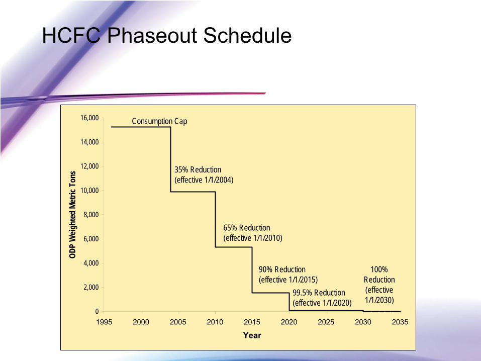
HCFC Phaseout Schedule
0
2,000
4,000
6,000
8,000
10,000
12,000
14,000
16,000
1995 2000 2005 2010 2015 2020 2025 2030 2035
Year
ODP
Weig
hted
Met
ric T
ons
Consumption Cap
35% Reduction (effective 1/1/2004)
65% Reduction(effective 1/1/2010)
90% Reduction(effective 1/1/2015)
99.5% Reduction (effective 1/1/2020)
100% Reduction (effective 1/1/2030)
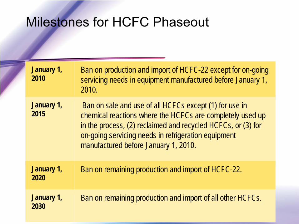
Milestones for HCFC Phaseout
January 1, 2010
Ban on production and import of HCFC-22 except for on-going servicing needs in equipment manufactured before January 1, 2010.
January 1, 2015
Ban on sale and use of all HCFCs except (1) for use in chemical reactions where the HCFCs are completely used up in the process, (2) reclaimed and recycled HCFCs, or (3) for on-going servicing needs in refrigeration equipment manufactured before January 1, 2010.
January 1, 2020
Ban on remaining production and import of HCFC-22.
January 1, 2030
Ban on remaining production and import of all other HCFCs.
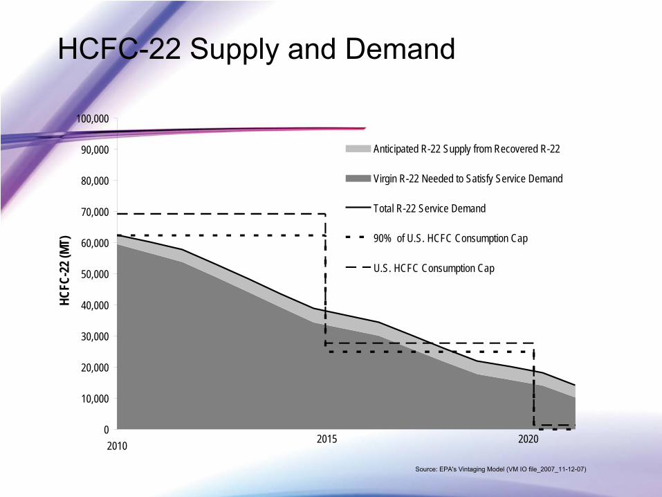
HCFC-22 Supply and Demand
0
10,000
20,000
30,000
40,000
50,000
60,000
70,000
80,000
90,000
100,000
2010
HCFC
-22 (
MT)
Anticipated R-22 Supply from Recovered R-22
Virgin R-22 Needed to Satisfy Service Demand
Total R-22 Service Demand
90% of U.S. HCFC Consumption Cap
U.S. HCFC Consumption Cap
2015 2020
Source: EPA's Vintaging
Model (VM IO file_2007_11-12-07)
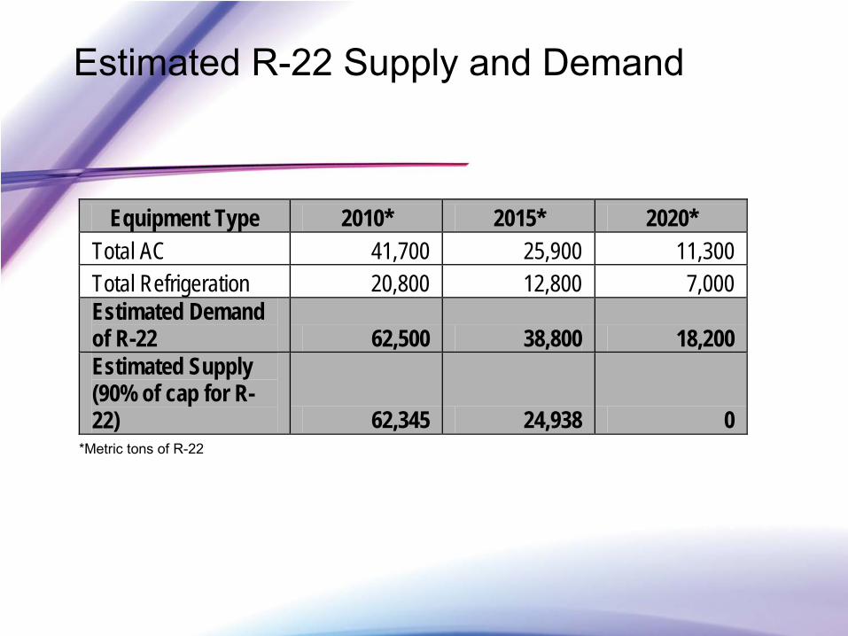
Estimated R-22 Supply and Demand
Equipment Type 2010* 2015* 2020* Total AC 41,700 25,900 11,300 Total Refrigeration 20,800 12,800 7,000 Estimated Demand of R-22 62,500 38,800 18,200 Estimated Supply (90% of cap for R-22) 62,345 24,938 0
*Metric tons of R-22
Servicing Existing HCFC-22 Equipment after 2010
•
In 2015, HCFC-22 needs will exceed the 2015 cap by more than 10,000 metric tons
•
Recovery and reuse needed to provide room under the cap and meet demand for all HCFCs
•
What can you do?
•
Improve service practices (recover, recycle, reclaim)
•
Fix leaks
•
Retrofit/Replace where economical
Servicing Existing HCFC-22 Equipment after 2010
•
You will not have to stop using HCFC-22
•
You will not have to replace existing equipment
•
Existing equipment using HCFC-22 can be serviced as usual
•
After 2010, supplies of HCFC-22 will be more limited
•
After 2020, only stockpiled or reclaimed supplies will be available to service equipment
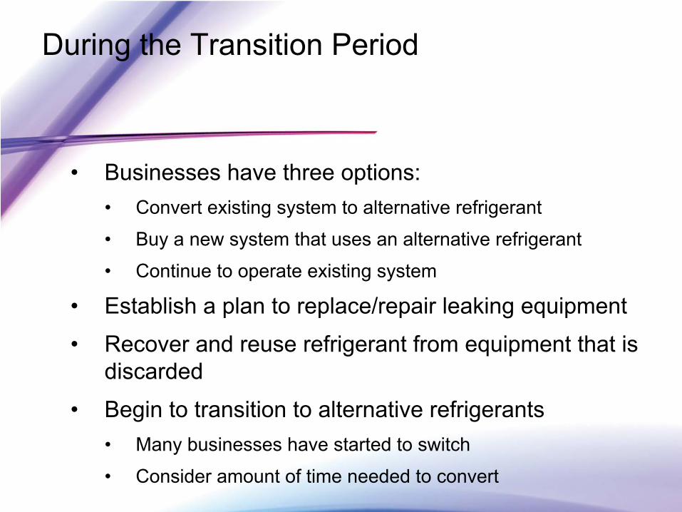
During the Transition Period
•
Businesses have three options: •
Convert existing system to alternative refrigerant
•
Buy a new system that uses an alternative refrigerant
•
Continue to operate existing system
•
Establish a plan to replace/repair leaking equipment
•
Recover and reuse refrigerant from equipment that is discarded
•
Begin to transition to alternative refrigerants•
Many businesses have started to switch
•
Consider amount of time needed to convert
•
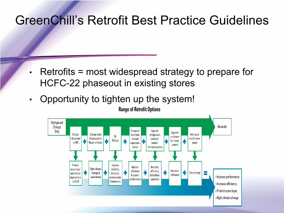
Retrofits = most widespread strategy to prepare for HCFC-22 phaseout in existing stores
•
Opportunity to tighten up the system!
GreenChill’s Retrofit Best Practice Guidelines
GreenChill’s Retrofit Best Practice Guidelines
•
Mission & Purpose/ Scope of the Guideline
•
The HCFC Situation–
Why Retrofit?•
Ozone Layer Protection and the Montreal Protocol
•
Montreal Protocol Implementation in the United States
•
HCFC-22 Supply and Demand
GreenChill’s Retrofit Guidelines -
Contents
•
HFC Refrigerant Retrofits•
HFC Retrofit Options
•
HFC Refrigerant only Retrofit•
Retrofitting with New Mechanicals and HFC Refrigerant
•
Leak Tightness Improvements during Retrofits•
Factors to consider when assessing retrofit options
•
Value/Cost Calculation•
Lab Tests on Retrofit Refrigerants vs. HCFC-22
GreenChill’s Retrofit Guidelines -
Contents
•
Best Practices for Transitioning to HFC Substitute Chemicals
•
Conversion Guidelines for HFC Substitute Chemicals
•
Best Practice Checklist for Conversion to HFC Substitute Chemicals
GreenChill Retrofit Guidelines -
Contents
•
Best Practices -
HCFC-22 End of Life•
End of Life Options for Refrigerants
•
Best Practices –
Recovery, Reclamation
•
Safety Information
•
Case Studies for R-422D, R407A, and 427A Retrofits•
Conversion Checklists for Specific HFC Substitute Chemicals
HCFC Replacement Refrigerants
•
The Business Case–
HCFC-22 is going away –
HCFC-22 price volatility likely–
Plan for a smooth and orderly transition –
Concentrate on the lowest cost solution
•
Refrigerant retrofits deliver value…–
By extending the life of existing corporate assets –
R22 is a valuable corporate asset–
Use R22 to servicing other stores–
Avoid heavy machine room investments–
Free up cash for the highest ROI business investments
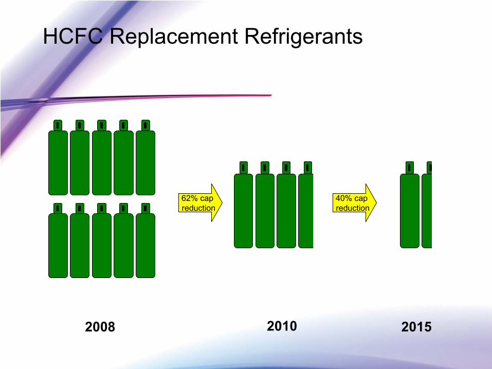
HCFC Replacement Refrigerants
62% cap reduction
2008 2010
40% cap reduction
2015
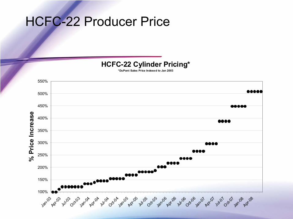
HCFC-22 Producer Price
HCFC-22 Cylinder Pricing**DuPont Sales Price Indexed to Jan 2003
100%
150%
200%
250%
300%
350%
400%
450%
500%
550%
Jan-0
3Apr-
03Ju
l-03
Oct-03
Jan-0
4Apr-
04Ju
l-04
Oct-04
Jan-0
5Apr-
05Ju
l-05
Oct-05
Jan-0
6Apr-
06Ju
l-06
Oct-06
Jan-0
7Apr-
07Ju
l-07
Oct-07
Jan-08
Apr-08
% P
rice
Incr
ease
HCFC-22 Replacement Refrigerants Availability
•
Future product availability is a function of–
Product Acceptance–
Producer commitment to manufacturing and selling–
Distribution network to service retail locations
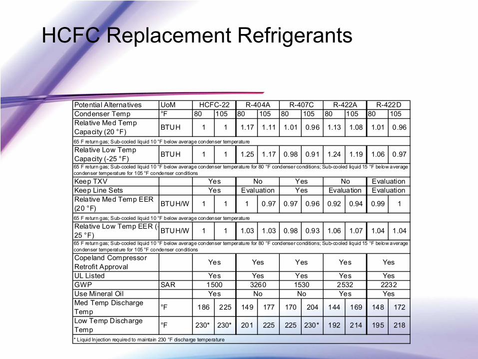
HCFC Replacement Refrigerants
Potential Alternatives UoMCondenser Temp °F 80 105 80 105 80 105 80 105 80 105Relative Med Temp Capacity (20 °F) BTUH 1 1 1.17 1.11 1.01 0.96 1.13 1.08 1.01 0.96
Relative Low Temp Capacity (-25 °F) BTUH 1 1 1.25 1.17 0.98 0.91 1.24 1.19 1.06 0.97
Keep TXV Keep Line SetsRelative Med Temp EER (20 °F) BTUH/W 1 1 1 0.97 0.97 0.96 0.92 0.94 0.99 1
Relative Low Temp EER (-25 °F) BTUH/W 1 1 1.03 1.03 0.98 0.93 1.06 1.07 1.04 1.04
Copeland Compressor Retrofit ApprovalUL ListedGWP SARUse Mineral OilMed Temp Discharge Temp °F 186 225 149 177 170 204 144 169 148 172
Low Temp Discharge Temp °F 230* 230* 201 225 225 230* 192 214 195 218
65 F return gas; Sub-cooled liquid 10 °F below average condenser temperature for 80 °F condenser conditions; Sub-cooled liquid 15 °F below average condenser temperature for 105 °F condenser conditions
* Liquid Injection required to maintain 230 °F discharge temperature
R-422D
65 F return gas; Sub-cooled liquid 10 °F below average condenser temperature
65 F return gas; Sub-cooled liquid 10 °F below average condenser temperature for 80 °F condenser conditions; Sub-cooled liquid 15 °F below average condenser temperature for 105 °F condenser conditions
65 F return gas; Sub-cooled liquid 10 °F below average condenser temperature
HCFC-22 R-404A R-407C R-422A
EvaluationYes Evaluation Yes Evaluation EvaluationYes No Yes No
2232Yes No No Yes Yes1500 3260 1530 2532
Yes
Yes Yes Yes Yes Yes
Yes Yes Yes Yes
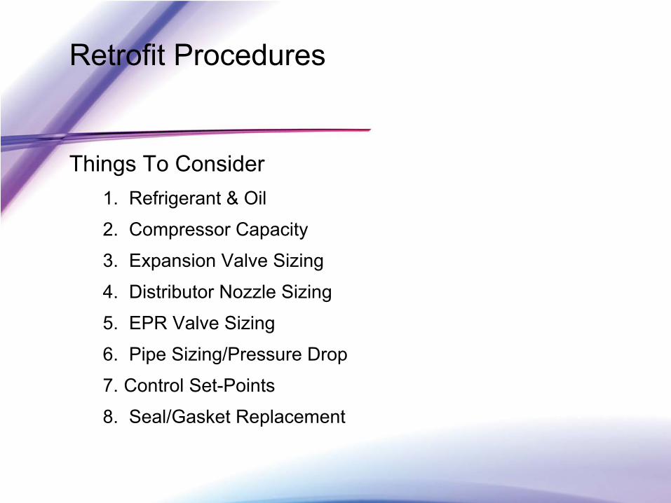
Retrofit Procedures
Things To Consider 1.
Refrigerant & Oil
2.
Compressor Capacity
3.
Expansion Valve Sizing
4.
Distributor Nozzle Sizing
5.
EPR Valve Sizing
6.
Pipe Sizing/Pressure Drop
7.
Control Set-Points
8.
Seal/Gasket Replacement
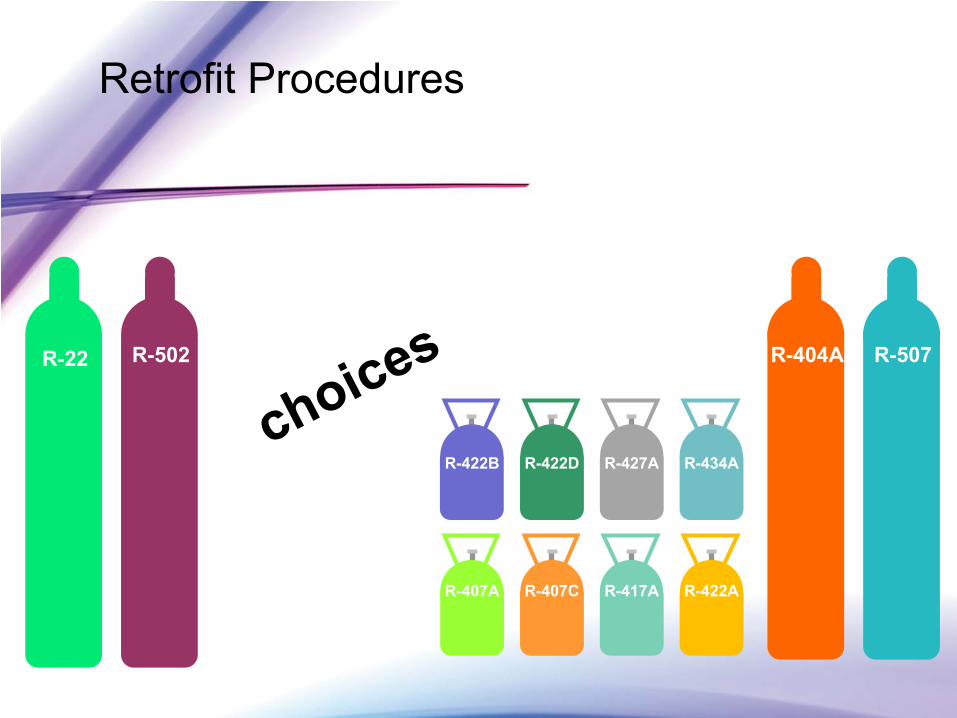
Retrofit Procedures
R-22 R-502 R-404A R-507
R-434AR-427AR-422D
R-417AR-407CR-407A
choices
R-422B
R-422A
Retrofit Procedures
R-22 R-502 R-404A R-507
R-434AR-427AR-422D
R-417AR-407CR-407A
R-422B
R-422A
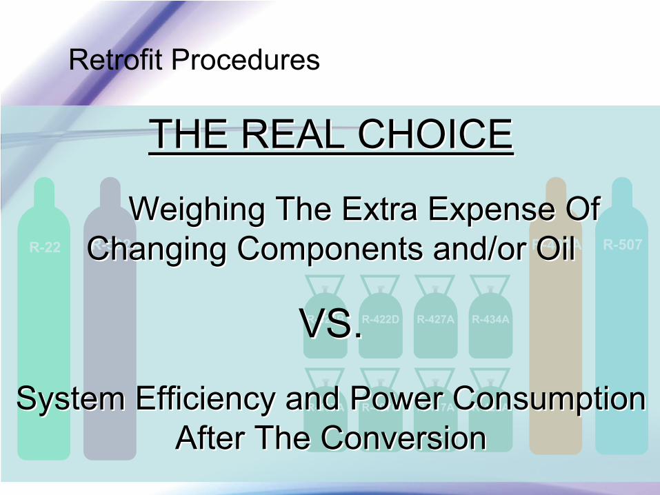
THE REAL CHOICETHE REAL CHOICE
Weighing The Extra Expense Of Weighing The Extra Expense Of Changing Components and/or Oil Changing Components and/or Oil
VS.VS.
System Efficiency and Power Consumption System Efficiency and Power Consumption After The ConversionAfter The Conversion
Retrofit Procedures
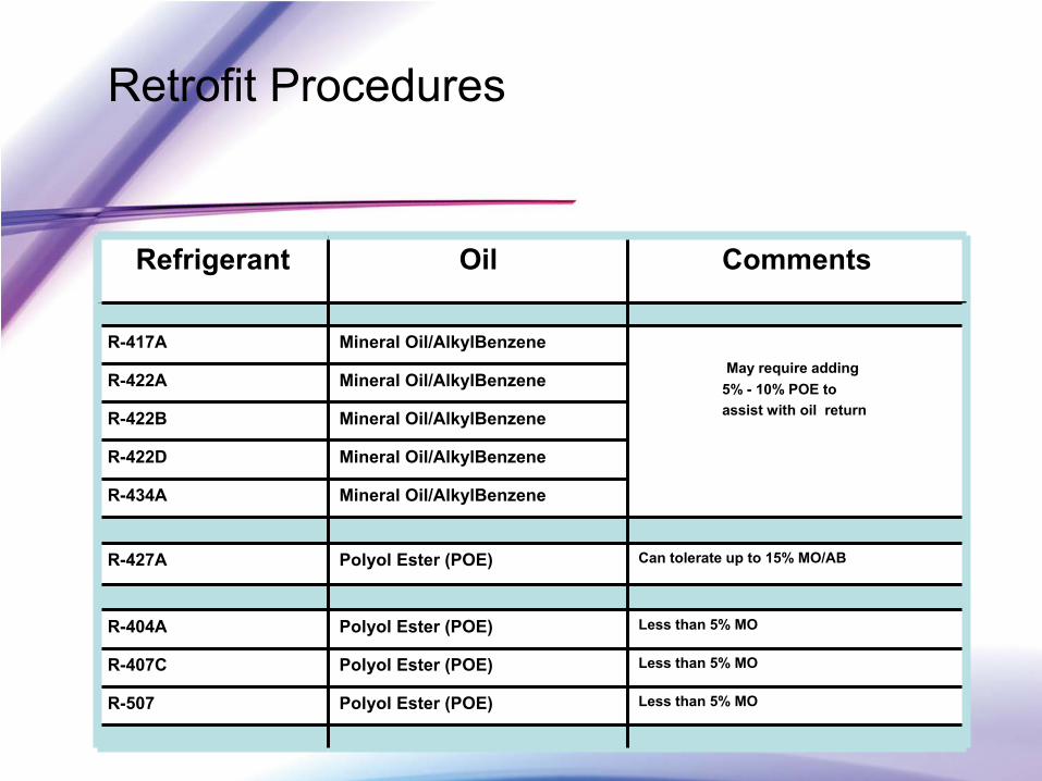
Refrigerant Oil Comments
R-417A Mineral Oil/AlkylBenzeneMay require adding
5% -
10% POE to assist with oil return
R-422A Mineral Oil/AlkylBenzene
R-422B Mineral Oil/AlkylBenzene
R-422D Mineral Oil/AlkylBenzene
R-434A Mineral Oil/AlkylBenzene
R-427A Polyol
Ester (POE) Can tolerate up to 15% MO/AB
R-404A Polyol
Ester (POE) Less than 5% MO
R-407C Polyol
Ester (POE) Less than 5% MO
R-507 Polyol
Ester (POE) Less than 5% MO

Retrofit Procedures Theoretical Compressor Capacities
As Compared to R-22
R-22 R-417A R-422A R-422D R-404A R-507
105ºF Condensing Temperature
+20ºF Evap
Temperature 50º
Liquid Temperature
100% 82.6% 97% 85% 108% 108%
105ºF Condensing Temperature
-25ºF Evap
Temperature 50º
Liquid Temperature
100% 86% 106% 90% 117% 117%
Retrofit Procedures
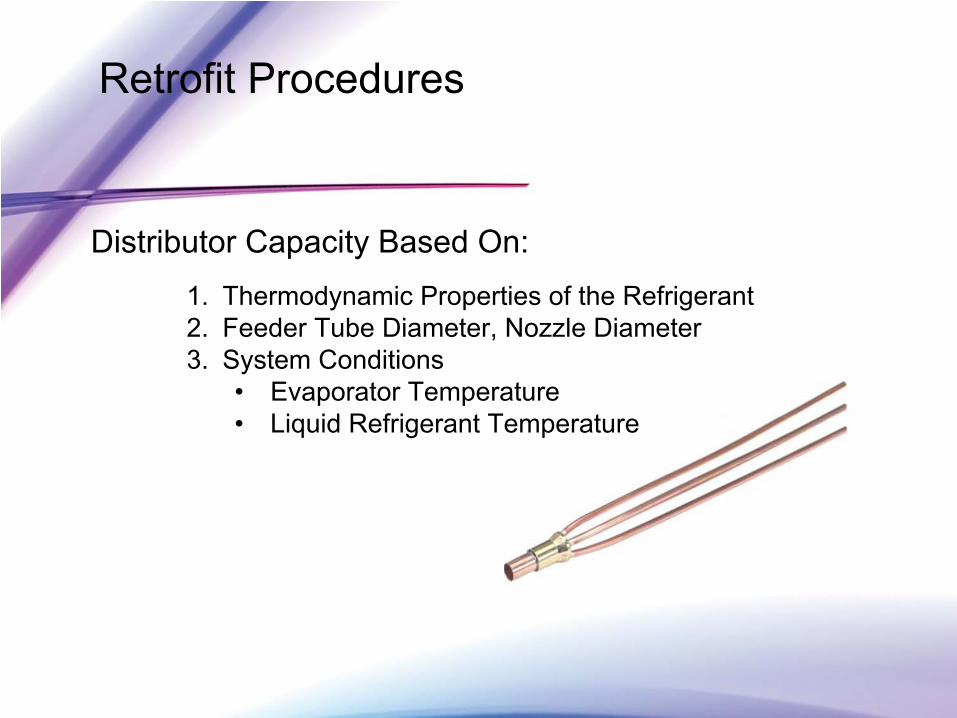
Distributor Capacity Based On:1.
Thermodynamic Properties of the Refrigerant2.
Feeder Tube Diameter, Nozzle Diameter3.
System Conditions•
Evaporator Temperature•
Liquid Refrigerant Temperature
Retrofit Procedures
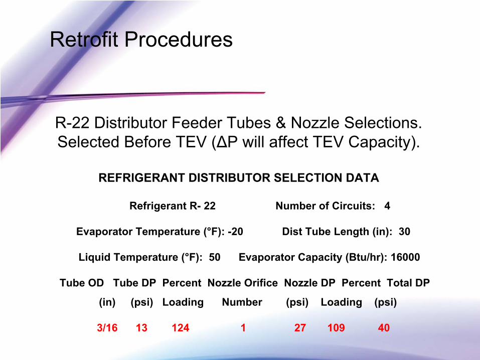
R-22 Distributor Feeder Tubes & Nozzle Selections. Selected Before TEV (ΔP will affect TEV Capacity).
REFRIGERANT DISTRIBUTOR SELECTION DATA
Refrigerant R-
22 Number of Circuits: 4
Evaporator Temperature (°F): -20 Dist Tube Length (in): 30
Liquid Temperature (°F): 50 Evaporator Capacity (Btu/hr): 16000
Tube OD Tube DP Percent Nozzle Orifice Nozzle DP Percent Total DP
(in) (psi) Loading Number (psi) Loading (psi)
3/16 13
124
1 27
109
40
Retrofit Procedures
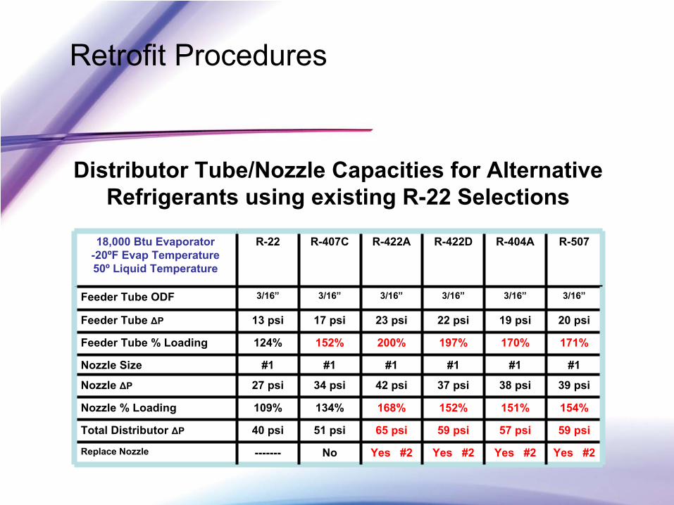
Distributor Tube/Nozzle Capacities for Alternative Refrigerants using existing R-22 Selections
18,000 Btu
Evaporator
-20ºF Evap
Temperature 50º
Liquid Temperature
R-22 R-407C R-422A R-422D R-404A R-507
Feeder Tube ODF 3/16” 3/16” 3/16” 3/16” 3/16” 3/16”
Feeder Tube ΔP 13 psi 17 psi 23 psi 22 psi 19 psi 20 psi
Feeder Tube % Loading 124% 152% 200% 197% 170% 171%
Nozzle Size #1 #1 #1 #1 #1 #1
Nozzle ΔP 27 psi 34 psi 42 psi 37 psi 38 psi 39 psi
Nozzle % Loading 109% 134% 168% 152% 151% 154%
Total Distributor ΔP 40 psi 51 psi 65 psi 59 psi 57 psi 59 psi
Replace Nozzle ------- No Yes #2 Yes #2 Yes #2 Yes #2
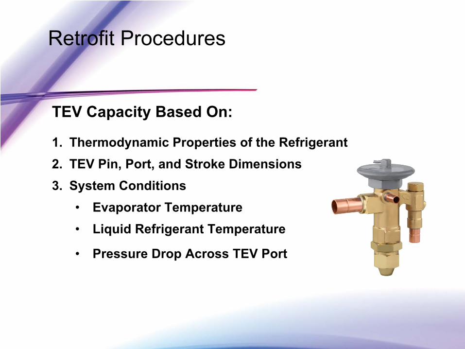
Retrofit Procedures
TEV Capacity Based On:
1.
Thermodynamic Properties of the Refrigerant2.
TEV Pin, Port, and Stroke Dimensions3.
System Conditions•
Evaporator Temperature•
Liquid Refrigerant Temperature
•
Pressure Drop Across TEV Port
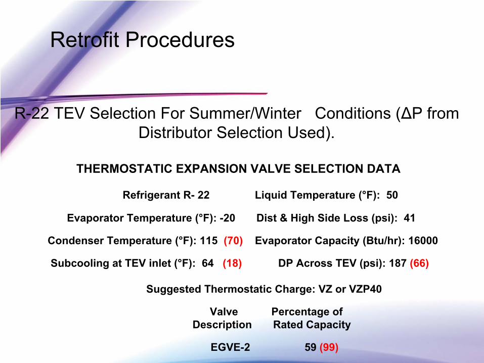
Retrofit Procedures
R-22 TEV Selection For Summer/Winter Conditions (ΔP from Distributor Selection Used).
THERMOSTATIC EXPANSION VALVE SELECTION DATA
Refrigerant R-
22 Liquid Temperature (°F): 50
Evaporator Temperature (°F): -20 Dist & High Side Loss (psi): 41
Condenser Temperature (°F): 115 (70) Evaporator Capacity (Btu/hr): 16000
Subcooling
at TEV inlet (°F): 64 (18) DP Across TEV (psi): 187 (66)
Suggested Thermostatic Charge: VZ or VZP40
Valve Percentage of Description Rated Capacity
EGVE-2 59
(99)
Retrofit Procedures
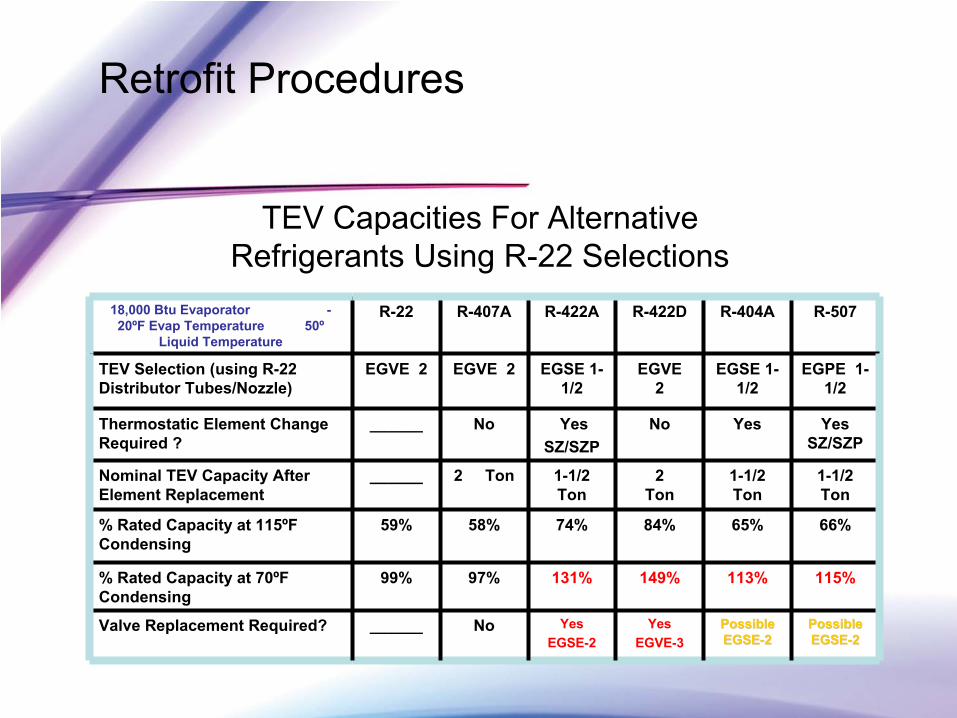
TEV Capacities For AlternativeRefrigerants Using R-22 Selections
18,000 Btu
Evaporator
-
20ºF Evap
Temperature 50º
Liquid Temperature
R-22 R-407A R-422A R-422D R-404A R-507
TEV Selection (using R-22 Distributor Tubes/Nozzle)
EGVE 2 EGVE 2 EGSE 1-
1/2EGVE
2EGSE 1-
1/2EGPE 1-
1/2
Thermostatic Element Change Required ?
______ No YesSZ/SZP
No Yes Yes SZ/SZP
Nominal TEV Capacity After Element Replacement
______ 2 Ton 1-1/2 Ton
2 Ton
1-1/2 Ton
1-1/2 Ton
% Rated Capacity at 115ºF Condensing
59% 58% 74% 84% 65% 66%
% Rated Capacity at 70ºF Condensing
99% 97% 131% 149% 113% 115%
Valve Replacement Required? ______ No YesEGSE-2
Yes EGVE-3
Possible Possible EGSEEGSE--22
Possible Possible EGSEEGSE--22
Retrofit Procedures
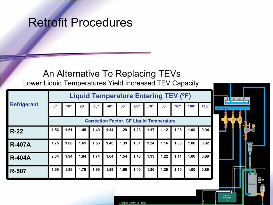
RefrigerantLiquid Temperature Entering TEV (ºF)
0º 10º 20º 30º 40º 50º 60º 70º 80º 90º 100º 110º
Correction Factor, CF Liquid Temperature
R-22 1.56 1.51 1.45 1.40 1.34 1.29 1.23 1.17 1.12 1.06 1.00 0.94
R-407A 1.75 1.68 1.61 1.53 1.46 1.39 1.31 1.24 1.16 1.08 1.00 0.92
R-404A 2.04 1.94 1.84 1.74 1.64 1.54 1.43 1.33 1.22 1.11 1.00 0.89
R-507 1.99 1.89 1.79 1.69 1.59 1.50 1.40 1.30 1.20 1.10 1.00 0.89
An Alternative To Replacing TEVsLower Liquid Temperatures Yield Increased TEV Capacity:
Retrofit Procedures
EPR Capacity Based On:1.
Evaporator Temperature
2.
Suction Vapor Temperature
•
ΔP Across Valve Port (Difference between EPR Set-Point and Common Suction Pressure –
for the circuit with the lowest design temperature this should be kept to a minimum).
Retrofit Procedures
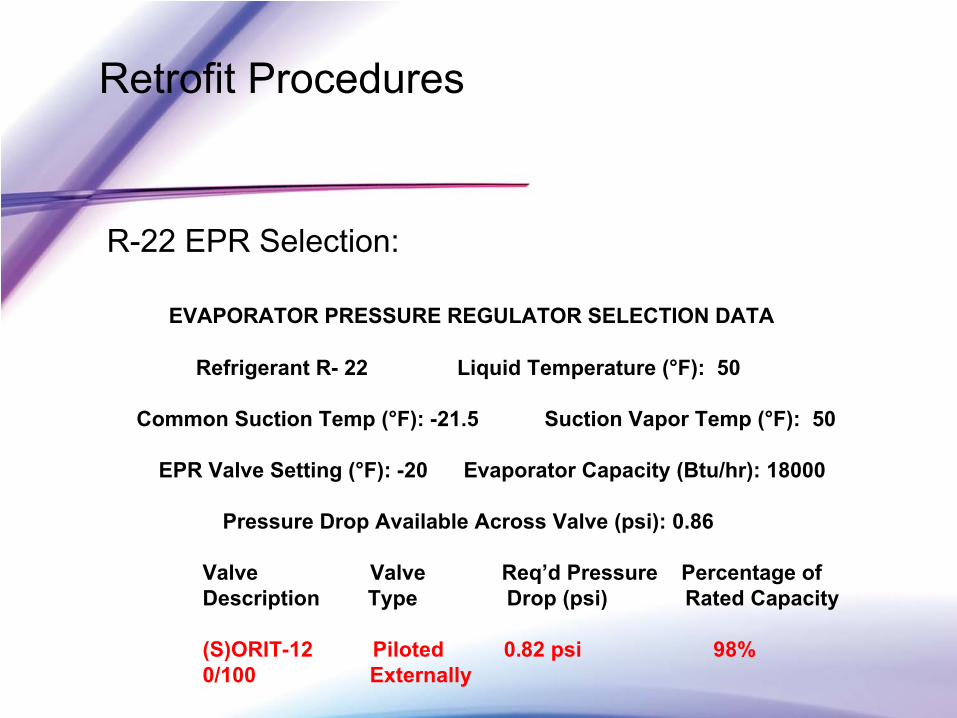
R-22 EPR Selection:
EVAPORATOR PRESSURE REGULATOR SELECTION DATA
Refrigerant R-
22 Liquid Temperature (°F): 50
Common Suction Temp (°F): -21.5
Suction Vapor Temp (°F): 50
EPR Valve Setting (°F): -20 Evaporator Capacity (Btu/hr): 18000
Pressure Drop Available Across Valve (psi): 0.86
Valve
Valve
Req’d
Pressure
Percentage ofDescription Type Drop (psi) Rated Capacity
(S)ORIT-12 Piloted 0.82 psi 98% 0/100 Externally
Retrofit Procedures
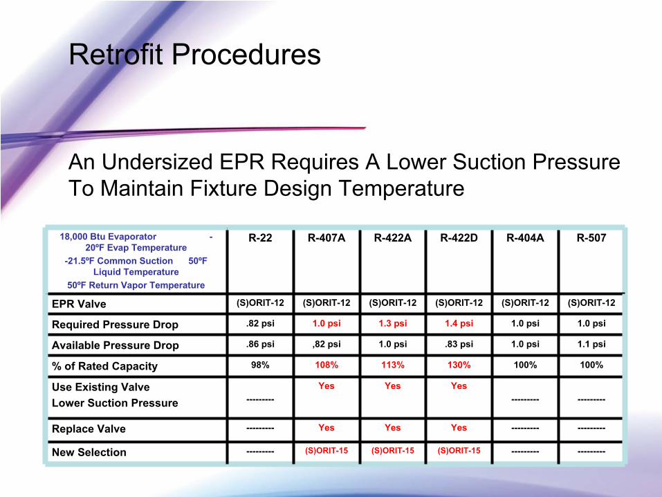
An Undersized EPR Requires A Lower Suction Pressure To Maintain Fixture Design Temperature
18,000 Btu
Evaporator
-
20ºF Evap
Temperature-21.5ºF
Common Suction 50ºF
Liquid Temperature50ºF Return Vapor Temperature
R-22 R-407A R-422A R-422D R-404A R-507
EPR Valve (S)ORIT-12 (S)ORIT-12 (S)ORIT-12 (S)ORIT-12 (S)ORIT-12 (S)ORIT-12
Required Pressure Drop .82 psi 1.0 psi 1.3 psi 1.4 psi 1.0 psi 1.0 psi
Available Pressure Drop .86 psi ,82 psi 1.0 psi .83 psi 1.0 psi 1.1 psi
% of Rated Capacity 98% 108% 113% 130% 100% 100%
Use Existing Valve Lower Suction Pressure ---------
Yes Yes Yes--------- ---------
Replace Valve --------- Yes Yes Yes --------- ---------
New Selection --------- (S)ORIT-15 (S)ORIT-15 (S)ORIT-15 --------- ---------
Retrofit Procedures
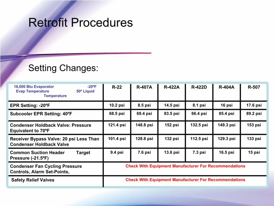
Setting Changes:
18,000 Btu
Evaporator
-20ºF Evap
Temperature 50º
Liquid Temperature
R-22 R-407A R-422A R-422D R-404A R-507
EPR Setting: -20ºF 10.2 psi 8.5 psi 14.5 psi 8.1 psi 16 psi 17.6 psi
Subcooler
EPR Setting: 40ºF 68.5 psi 69.4 psi 83.5 psi 66.4 psi 85.4 psi 89.2 psi
Condenser Holdback Valve: Pressure Equivalent to 70ºF
121.4 psi 148.8 psi 152 psi 132.5 psi 149.3 psi 153 psi
Receiver Bypass Valve: 20 psi Less Than Condenser Holdback Valve
101.4 psi 128.8 psi 132 psi 112.5 psi 129.3 psi 133 psi
Common Suction Header Target Pressure (-21.5ºF)
9.4 psi 7.6 psi 13.6 psi 7.3 psi 16.5 psi 15 psi
Condenser Fan Cycling Pressure Controls, Alarm Set-Points,
Check With Equipment Manufacturer For Recommendations
Safety Relief Valves Check With Equipment Manufacturer For Recommendations
Retrofit Procedures Seals and Gaskets
Refrigerants and Lubricants:How Do They Affect Elastomers?
Test Results Show:
A certain amount of swell, and loss of physical properties when exposed to refrigerants/oil.
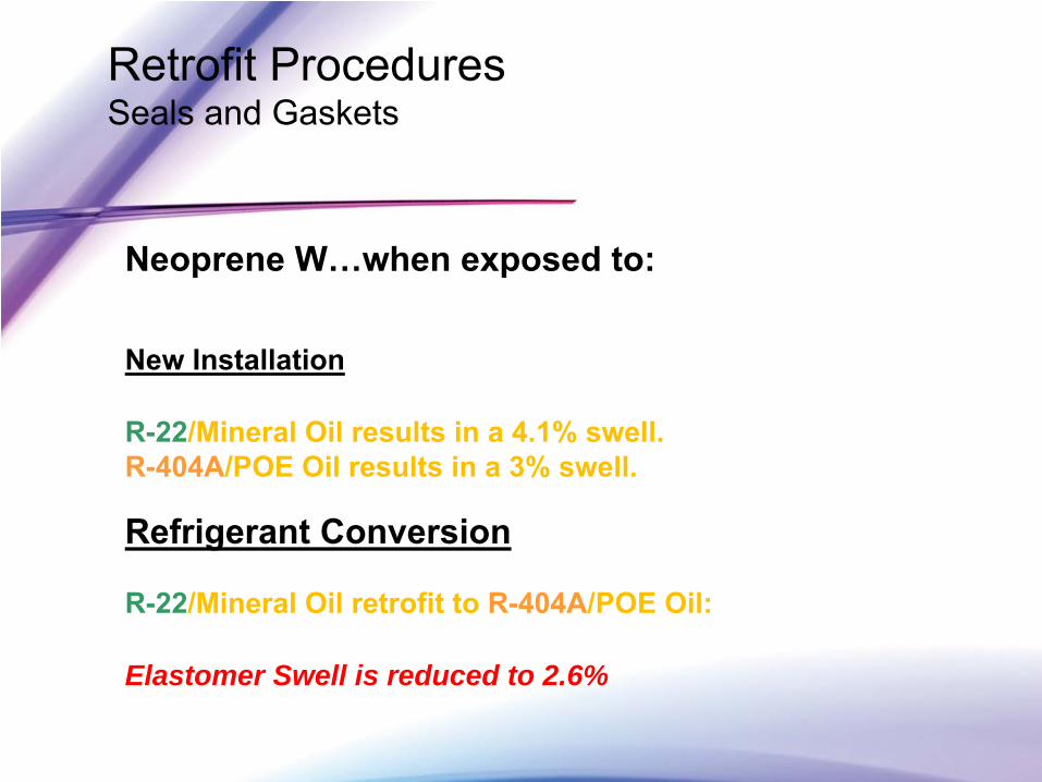
Retrofit Procedures Seals and Gaskets
Neoprene W…when exposed to:
New Installation
R-22/Mineral Oil results in a 4.1% swell.R-404A/POE Oil results in a 3% swell.
Refrigerant Conversion
R-22/Mineral Oil retrofit to R-404A/POE Oil:
Elastomer Swell is reduced to 2.6%
Retrofit Procedures Seals and Gaskets
Components which require may have elastomergaskets/seals…if so, replacement is required.•
Solenoid valves•
3-way reversing valves•
Schraeder
valve cores and caps.•
Evaporator Pressure Regulators (EPRs).•
Some older style ball valves may need replacement.
Retrofit Procedures
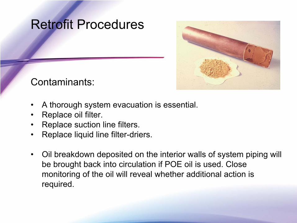
Contaminants:
•
A thorough system evacuation is essential.•
Replace oil filter.•
Replace suction line filters.•
Replace liquid line filter-driers.
•
Oil breakdown deposited on the interior walls of system piping will be brought back into circulation if POE oil is used. Close monitoring of the oil will reveal whether additional action is required.
Retailer Experiences
•
Conversion data•
Conversion engineering process
•
Capacity, Oil, Valves, others•
Refrigerant choice
•
Follow up on maintenance, MO to POE•
Lifecycle cost, total cost of ownership
•
Leak potential variability post conversion
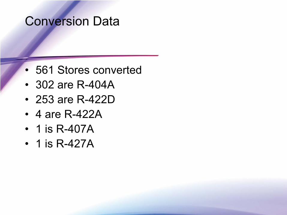
Conversion Data
•
561 Stores converted•
302 are R-404A
•
253 are R-422D•
4 are R-422A
•
1 is R-407A•
1 is R-427A
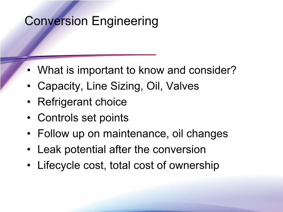
Conversion Engineering
•
What is important to know and consider?•
Capacity, Line Sizing, Oil, Valves
•
Refrigerant choice •
Controls set points
•
Follow up on maintenance, oil changes•
Leak potential after the conversion
•
Lifecycle cost, total cost of ownership
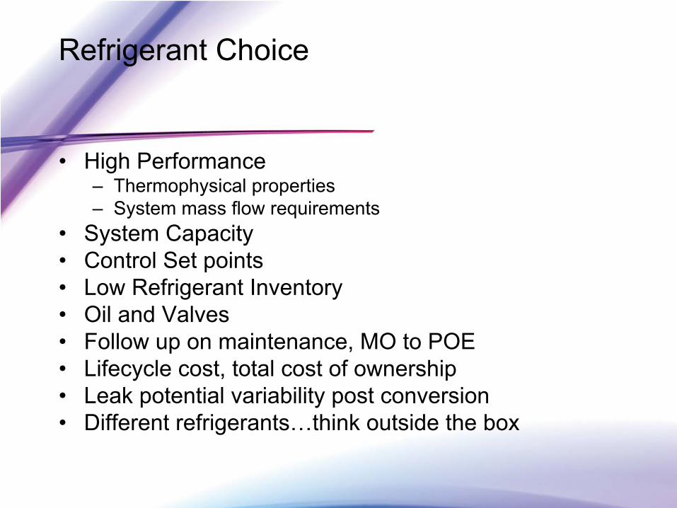
Refrigerant Choice
•
High Performance –
Thermophysical
properties–
System mass flow requirements•
System Capacity
•
Control Set points•
Low Refrigerant Inventory
•
Oil and Valves•
Follow up on maintenance, MO to POE
•
Lifecycle cost, total cost of ownership•
Leak potential variability post conversion
•
Different refrigerants…think outside the box
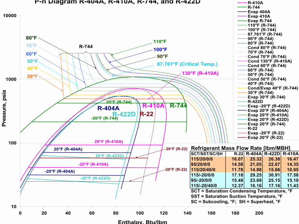
P-h Diagram R-404A, R-410A, R-744, and R-422D
10
100
1000
10000
0 20 40 60 80 100 120 140 160 180 200
Enthalpy, Btu/lbm
Pres
sure
, psi
aR-410AR-744Evap 404AEvap 410AEvap R-744110°F (R-744)100°F (R-744)87.761°F (R-744)90°F (R-744)80°F (R-744)Cond 80°F (R-744)70°F (R-744)Cond 70°F (R-744)Cond 130°F (R-410A)Cond 60°F (R-744)60°F (R-744)50°F (R-744)Cond 50°F (R-744)40°F (R-744)Cond/Evap 40°F (R-744)30°F (R-744)Evap 30°F (R-744)R-422DEvap -20°F (R-422D)Evap 20°F (R-404A)Evap 20°F (R-410A)Evap 20°F (R-422D)Evap 20°F (R-744)R-22Evap -20°F (R-22)Evap 20°F (R-22)
-20°F (R-744)
-20°F (R-410A)
-20°F (R-404A)
110°F
100°F
87.761°F (Critical Temp.)90°F
80°F70°F
60°F
130°F (R-410A)
50°F40°F30°F
R-404A R-410A R-744
-20°F (R-422D)
20°F (R-404A)
20°F (R-410A)
20°F (R-422D)
20°F (R-744)
R-422D R-22
20°F (R-22)
-20°F (R-22)
R-744
Refrigerant Mass Flow Rate [lbm/MBH]SCT/SST/SC/SH R-22 R-404A R-422D R-410A115/20/0/0 16.07 25.32 26.38 16.4795/20/0/0 14.58 21.05 22.07 14.35115/20/40/0 11.78 14.88 15.66 10.95115/-20/0/0 17.18 29.25 30.91 17.5895/-20/0/0 15.48 23.69 25.15 15.19115/-20/40/0 12.37 16.16 17.16 11.43SCT = Saturation Condensing Temperature, °FSST = Saturation Suction Temperature, °FSC = Subcooling, °F; SH = Superheat, °F
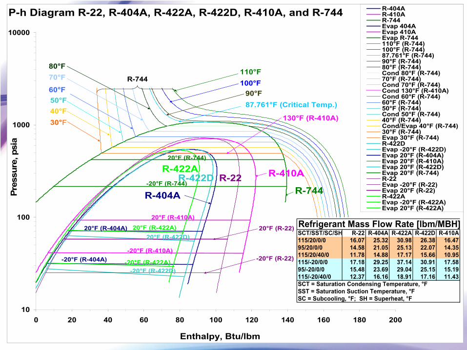
P-h Diagram R-22, R-404A, R-422A, R-422D, R-410A, and R-744
10
100
1000
10000
0 20 40 60 80 100 120 140 160 180 200
Enthalpy, Btu/lbm
Pres
sure
, psi
aR-404AR-410AR-744Evap 404AEvap 410AEvap R-744110°F (R-744)100°F (R-744)87.761°F (R-744)90°F (R-744)80°F (R-744)Cond 80°F (R-744)70°F (R-744)Cond 70°F (R-744)Cond 130°F (R-410A)Cond 60°F (R-744)60°F (R-744)50°F (R-744)Cond 50°F (R-744)40°F (R-744)Cond/Evap 40°F (R-744)30°F (R-744)Evap 30°F (R-744)R-422DEvap -20°F (R-422D)Evap 20°F (R-404A)Evap 20°F (R-410A)Evap 20°F (R-422D)Evap 20°F (R-744)R-22Evap -20°F (R-22)Evap 20°F (R-22)R-422AEvap -20°F (R-422A)Evap 20°F (R-422A)
-20°F (R-744)
-20°F (R-410A)-20°F (R-404A)
110°F100°F
87.761°F (Critical Temp.)90°F
80°F70°F
60°F
130°F (R-410A)
50°F40°F30°F
R-404A
R-410A
R-744
-20°F (R-422D)
20°F (R-404A)
20°F (R-410A)
20°F (R-422D)
20°F (R-744)
R-422D R-22
20°F (R-22)
-20°F (R-22)
20°F (R-422A)
-20°F (R-422A)
R-422A
R-744
Refrigerant Mass Flow Rate [lbm/MBH]SCT/SST/SC/SH R-22 R-404A R-422A R-422D R-410A115/20/0/0 16.07 25.32 30.98 26.38 16.4795/20/0/0 14.58 21.05 25.13 22.07 14.35115/20/40/0 11.78 14.88 17.17 15.66 10.95115/-20/0/0 17.18 29.25 37.14 30.91 17.5895/-20/0/0 15.48 23.69 29.04 25.15 15.19115/-20/40/0 12.37 16.16 18.91 17.16 11.43SCT = Saturation Condensing Temperature, °FSST = Saturation Suction Temperature, °FSC = Subcooling, °F; SH = Superheat, °F
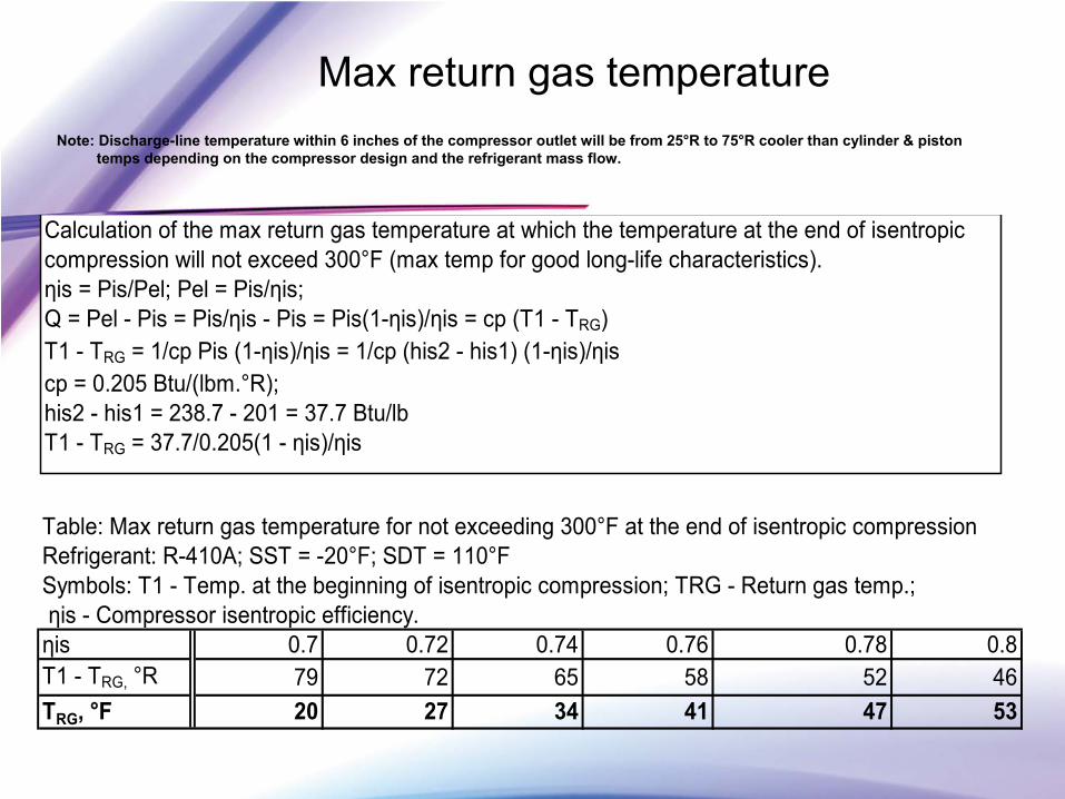
Max return gas temperatureNote: Discharge-line temperature within 6 inches of the compressor outlet will be from 25°R to 75°R cooler than cylinder & piston
temps depending on the compressor design and the refrigerant mass flow.
Table: Max return gas temperature for not exceeding 300°F at the end of isentropic compressionRefrigerant: R-410A; SST = -20°F; SDT = 110°F Symbols: T1 - Temp. at the beginning of isentropic compression; TRG - Return gas temp.; ηis - Compressor isentropic efficiency.ηis 0.7 0.72 0.74 0.76 0.78 0.8T1 - TRG, °R 79 72 65 58 52 46TRG, °F 20 27 34 41 47 53
Calculation of the max return gas temperature at which the temperature at the end of isentropic compression will not exceed 300°F (max temp for good long-life characteristics). ηis = Pis/Pel; Pel = Pis/ηis; Q = Pel - Pis = Pis/ηis - Pis = Pis(1-ηis)/ηis = cp (T1 - TRG)T1 - TRG = 1/cp Pis (1-ηis)/ηis = 1/cp (his2 - his1) (1-ηis)/ηiscp = 0.205 Btu/(lbm.°R); his2 - his1 = 238.7 - 201 = 37.7 Btu/lbT1 - TRG = 37.7/0.205(1 - ηis)/ηis
Total Cost of Ownership -
TCO
•
Equipment Costs •
Installed Costs
•
Operational Costs (energy)•
Maintenance Costs
•
Environmental Stewardship•
TCO has to be simple and cost effective
Presenter Contact Information
•
Keilly Witman, US EPA –
•
Nick Strickland, DuPont–
•
Dave Demma, Sporlan–
•
Richard Royal, Wal-Mart–
Contact Info –
Phaseout and Regulatory
•
US EPA -
Keilly Witman •
[email protected], 202-343-9742
•
Phaseout: Ross Brennan•
[email protected], 202-343-9226
•
For Sec. 608: Julius Banks,•
[email protected], 202-343-9870
•
GreenChill
Advanced Refrigeration Partnership•
www.epa.gov/greenchill
•
Additional Info:•
http://www.epa.gov/ozone/title6/phaseout/classtwo.html•
http://www.epa.gov/ozone/title6/allowance.html