Embed Size (px)
Citation preview
.
.
.
1
.
-
Parts Manual forQT Series Compressor
Model QT-I 5Record of Change 101
50250-101 November 1996
Q
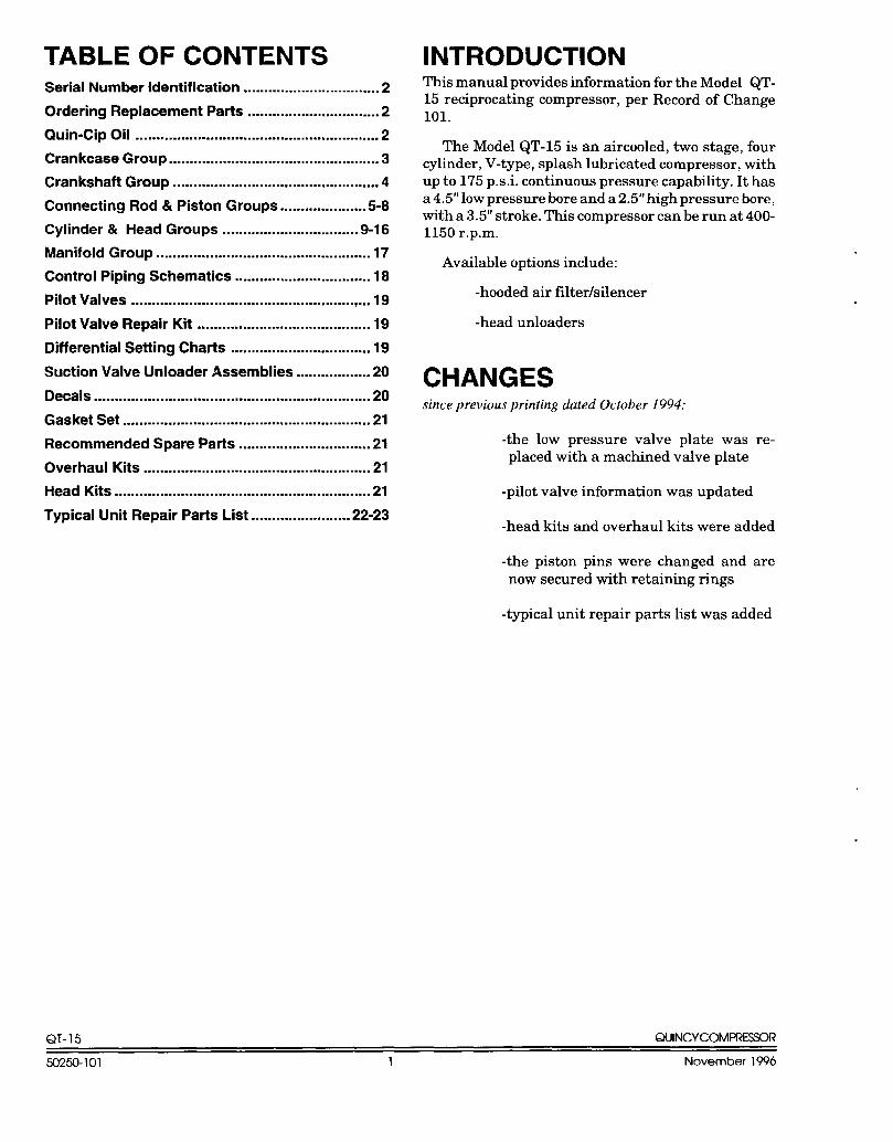
TABLE OF CONTENTSSerial Number Identification ................................. 2
Ordering Replacement Parts ................................ 2
Quin-Cip Oil ........................................................... 2
Crankcase Group ................................................... 3
Crankshaft Group .................................................. 4
Connecting Rod & Piston Groups .....................5-8
Cylinder & Head Groups .................................9-16
Manifold Group .................................................... 17
Control Piping Schematics ................................. 18
Pilot Valves .......................................................... 19
Pilot Valve Repair Klt .......................................... 19
Differential Setting Charts .................................. 19
Suction Valve Unloader Assemblies ..................20
Decals ................................................................... 20
Gasket Set ............................................................ 21
Recommended Spare Parts ................................ 21
Overhaul Kits ....................................................... 21
Head Kits .............................................................. 21
Typical Unit Repair Parts List ........................ 22-23
INTRODUCTIONThis manual provides information for the Model QT-15 reciprocating compressor, per Record of Change101.
The Model QT-15 is an aircooled, two stage, fourcylinder, V-type, splash lubricated compressor, withup to 175 p.s .i. continuous pressure capability. It hasa 4.5” low pressure bore and a 2.5” high pressure bore,with a 3.5” stroke. This compressor can be run at 400-1150r.p.m.
Available options include:
-hooded air filter/silencer
-head unloaders
CHANGESsince previous printing dated October 1994:
-the low pressure valve plate was re-placed with a machined valve plate
-pilot valve information was updated
-head kits and overhaul kits were added
-the piston pins were changed and arenow secured with retaining rings
-typical unit repair parts list was added
QT- 15 QUINCYCOMPREWR
50250-101 1 November 1996
—
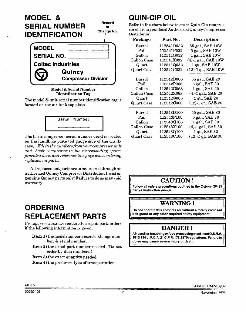
MODEL &Record
SERIAL NUMBER ofIDENTIFICATION
Change No.
Iv [ *
MODELI
SERIAL NO. .
Coltec Industries
@QuincyCompressor Division
dModel & Serial Nmnber
Identi13cation Tag
The model & unit serial number identification tag islocated on the air tank top plate.
*Serial Number
The basic compressor serial number decal is locatedon the handhole plate (oil gauge side of the crank-case). Fill in the numbers from your compressor unitand basic compressor in the corresponding spacesprovided here, and reference this page when ordering—replacement parts.
AN replacement parts are to be ordered through anauthorized Quincy Compressor Distributor, Insist ongenuine Quincy parts only! Failure to do so may voidwarranty.
ORDERINGREPLACEMENT PARTSPrompt service can be rendered on repair parts ordersif the following information is given:
Item 1) the model number, record of change num-ber, & serial number.
Item 2) the exact part number needed, (Do notorder by item numbers. )
Item 3) the exact quantity needed.
Item 4) the preferred type of transportation.
—
QUIN-CIP OILRefer to the chart below to order Quin-Cip compres-sor oil from your local Authorized Quincy CompressorDistributor.
Package Part No. Description
Barrel 112541D032 55 gal., SAE 10WPail 112541P032 5 gal., SAE 10W
Gallon 112541G032 1 gal., SAE IOWGallon Case l12541X032 (4)-1 gal,, SAE 10W
Quart 112541Q032 1 qt., SAE lowQuart Case 112541C032 (12)-1 qt., SAE 10W
Barrel 112542D068 55 gal., SAE 20Pail 112542P068 5 gal., SAE 20
Gallon 112542G068 1 gal., SAE 20Gallon Case 112542X068 (4)-1 gal., SAE 20
Quart 112542Q068 1 qt., SAE 20Quart Case 112542C068 (12)-1 qt., SAE 20
Barrel 112543D1OO 55 gal., SAE 30Pail 112543P1OO 5 gal., SAE 30
Gallon 112543G1OO 1 gal., SAE 30Gallon Case 112543X1OO (4)-1 gal., SAE 30
Quart 112543Q1OO 1 qt., SAE 30Quart Case 112543C1OO (12)-1 qt., SAE 30
CAUTION !1Follow all safety precautions outlined in the Quincy QR-25
Series instruction manual.
IIIDo not operate this compressor without a totally enclosed
belt guard or any other required safety equipment.
DANGER !Air used for breathing or food processing must meet O. S.H.A.1910.134 or F.D.A. 21 C.F,R. 178.3570 regulations, Failure todo so may cause severe injury or death.
QT- 15 QUINCYCOMPRESSOR
50250-101 2 November 1996
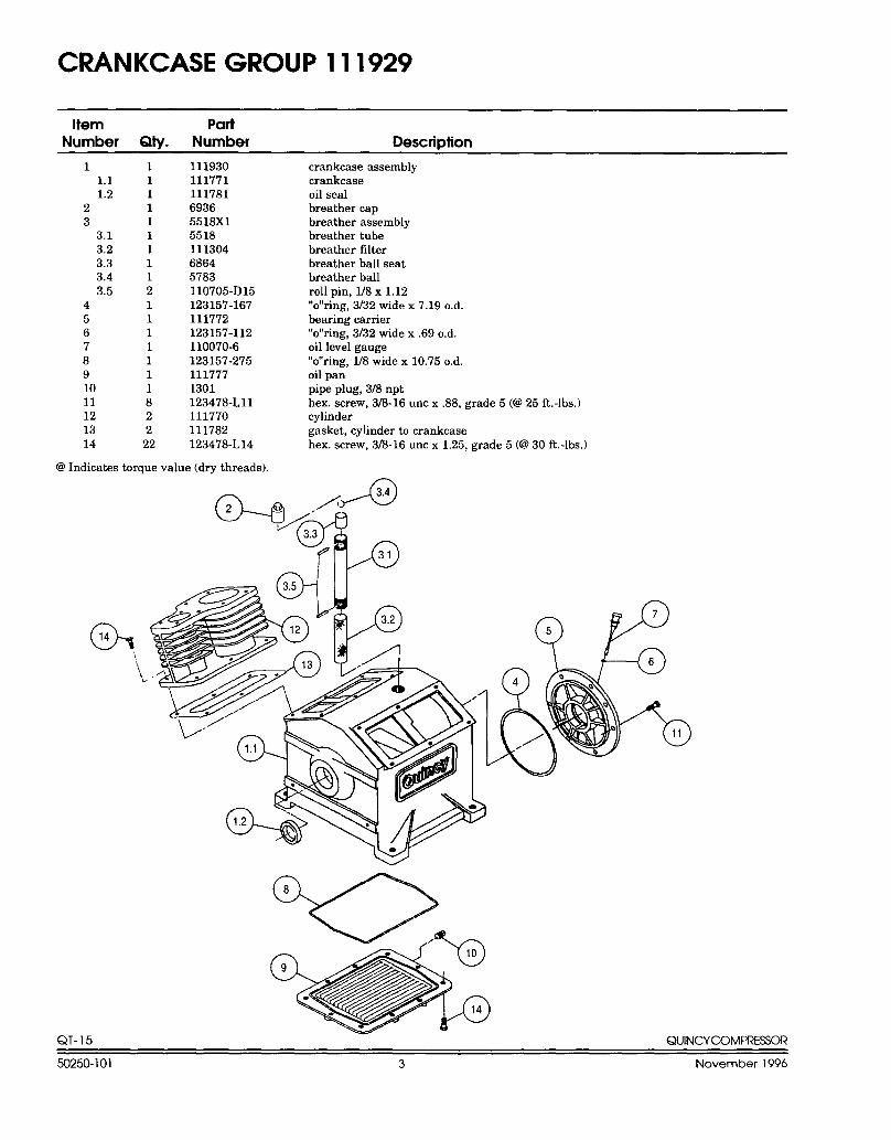
CRANKCASE GROUP 111929
Item PartNumber QtY. Number Descridion
11.11.2
23
3.13.23.33.43.5
4567891011121314
11111111121111111822
22
11193011177111178169365518X15518111304686457831107 O5-D15123157-167111772123157-112110070-6123157-2751117771301123478-L1l111770111782123478-L14
crankcase assemblycrankcaseoil sealbreather capbreather assemblybreather tubebreather filterbreather ball seatbreather ballroll pin, l/8 x 1.12“o’’ring, 3/32 wide x 7.19 o.d.bearing carrier“o’’ring, 3132 wide x .69 o.d.oil level gauge“o’’ring, l/8 wide x 10.75 o.d,oil panpipe plug, 3/8 npthex. screw, 3/8-16 unc x .88, grade 5 (6225 ft.-lbs,)cylindergasket, cylinder to crankcasehex. screw, 3/8-16 unc x 1.25, grade 5 (@30 ft.-lbs.)
@ Indicates torque value (dry threads).
G14
‘\
L
QT- 15 QUINCYCOMPRESSOR
50250-101 3 November 1996
—. -.. . . .
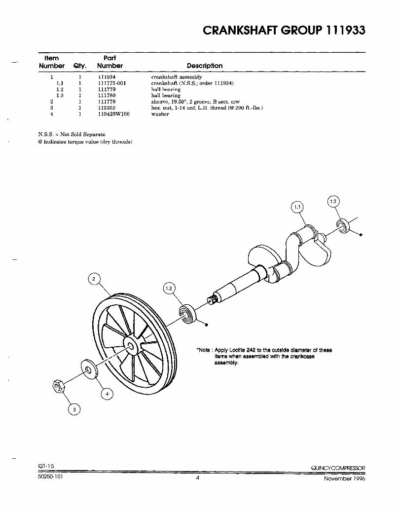
CRANKSHAFT GROUP 111933
Hem PartNumber Qty. Number Description
—
1 1 111934 crankehafl assembly1.1 1 111775-001 crankshatl(N. S.S.; order 111934)1.2 1 111779 ball bearing1,3 1 111780 ball bearing
2 1 111776 sheave, 19,50”, 2 groove, Bsect. CCVJ3 1 112352 hex, nut, 1-14 unf, L.H. thread (CP200 ft.-lbs. )4 1 110428W1OO washer
N.S.S. = Not Sold Separate
@ Indicates torque value (dry threads)
●Note : Apply Loctlte 242 to the outelde diameter of theseIteme when aeeembled with the crankcaeeaseembly.
o3
QT- 15 QUINCYCOMPRESSOR
50250-101 4 November 1996
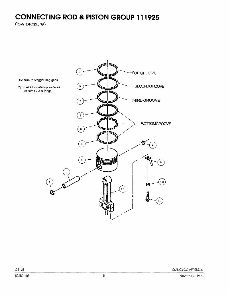
CONNECTING ROD & PISTON GROUP 111925(lowpressure)
Be sure to stagger ring gaps.
Pip marks indicate top surfacesof items 7 & 9 (rings),
Jll II I I
)/
i
i9’-@
b1.2
QT-15 QUINCVCOMPRESSOR
50250-101 5 November 1996
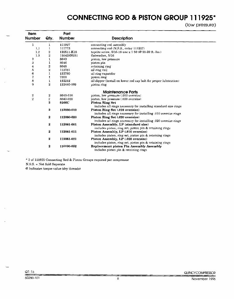
CONNECTING ROD & PISTON GROUP 11 1925*(low pressure)
Item Part—Number QtY. Number Descridion
—
1 11.1 11.2 21.3 2
2 13 14 25 26 17 18 19 2
2 22 2
2
2
2
2
2
2
2
111927111773110511-K15110428NO318643864686481127811127807351112212112440-009
8643-0108643-0208166C
112080-010
112080-020
112081-001
112081-011
112081-021
110190-052
connecting rod assemblyconnecting rod (NS.S., order 111927)taptite screw, 5/16-18 unc x 150 (@ 20-22 ft. -lbs.)flatwasher, 5/16piston, low pressurepiston pinretaining ringoil ring railoil ring expanderpiston ringoil dipper (install on lower rod cap bolt for proper lubrication)piston ring
Maintenance Partspiston, low pressure (.010 oversize)piston, low pressure (.020 oversize)Piston Ring Set
includes all rings necessary for installing standard size ringsPiston Ring Set (.010 oversize)
includes all rings necessary for installing .010 oversize ringsPiston Ring Set (.020 oversize)
includes all rings necessary for installing ,020 oversize ringsPiston Assembly, LP (standard size)
includes piston, ring set, piston pin & retaimng ringsPiston Assembly, LP (.010 oversize)
includes piston, ring set, piston pin & retaining ringsPiston Assembly, LP (.020 oversize)
includes piston, ring set, piston pin & retaining ringsReplacement piston Pin Assembly Assembly
includes piston pin & retaining rings
* 2 of 111925 Connecting Rod & Piston Groups required per compressor
N,S.S. = Not Sold Separate
@ Indicates torque value (dry threads)
.
QT-15 QUINCYCOMFi?ESSOR
50250-101 6 November 1996
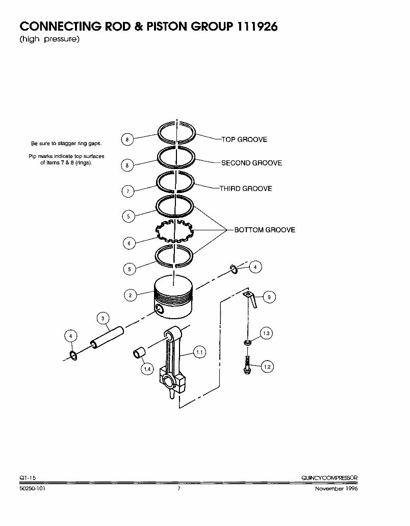
CONNECTING ROD & PISTON GROUP 111926(high pressure)
Be sure to stagger ring gaps.
Pip marks indicate top surfacesof items 7 & 8 (rings).
AI>..-,a--’,~l>TH,...ROOVE
5
+
BOTTOM GROOVE
6
~<~+
u !//
QT-15 QUINCYCOMPRESSOR
50250-101 7 November 1996
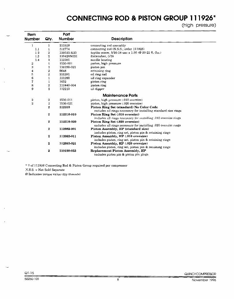
CONNECTING ROD & PISTON GROUP 11 1926*(high pressure)
Item PartNumber Qty. Number Description
—
1 11,1 112 21.3 21,4 1
2 13 14 25 26 17 18 29 1
2 22 2
2
2
2
2
2
2
2
111928111774110511-K15110428NO311123011530-001110190-02186481112811112801652112440-004112212
1530-0111530-021112318
112318-010
112318-020
112082-001
112082-011
112082-021
110190-053
connecting rod assemblyconnecting rod(N.S.S,; order 111928)taptite screw, 5/16 -18uncx 1.50 (c?220-22 ft.-lbs.)flatwasher, 5/16needle bearingpiston, high pressurepiston pinretaining ringoil ring railoil ring expanderpiston ringpiston ringoil dipper
Maintenance Partspiston, high pressure (.010 oversize)piston, high pressure (.020 oversize)Piston Ring Set (standard) No Color Code
includes all rings necessary for installing standard size ringsPiston Ring Set (.010 oversize)
includes all rings necessary for installing .010 oversize ringsPiston Ring Set (.020 oversize)
includes all rings necessary for installing .020 oversize ringsPiston Assembly, HP (standard size)
includes piston, ring set, piston pin & retaining ringsPiston Assembly, HP (.010 oversize)
includes piston, ring set, piston pin & retaining ringsPiston Assembly, HP (.020 oversize)
includes piston, ring set, piston pin & retaining ringsReplacement Piston Aasembh, HP.,
includes piston pin & piston pin plugs
* 2 of 111926 Connecting Rod & Piston Group required per compressor
N.S,S. = Not Sold Separate
@ Indicates torque value (dry threads)
QT- 15 QUINCYCOMFRESSOR
50250-101 8 November 1996
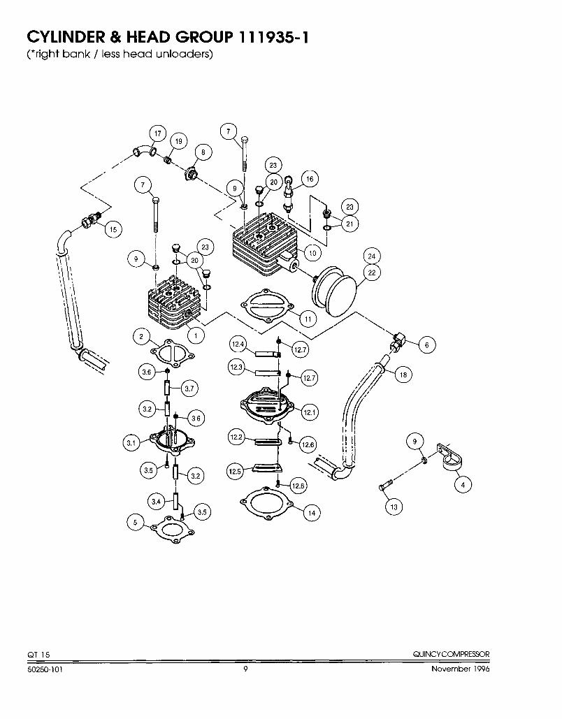
CYLINDER & HEAD GROUP 111935-1(*right bank / less head unloaders)
/“,/’
<
043.2
&
36
3,1
d~ 3.2
%
3.4
-3”5
%
7
QT-15 QUINCVCOMPRESSOR
50250-101 9 November 1996
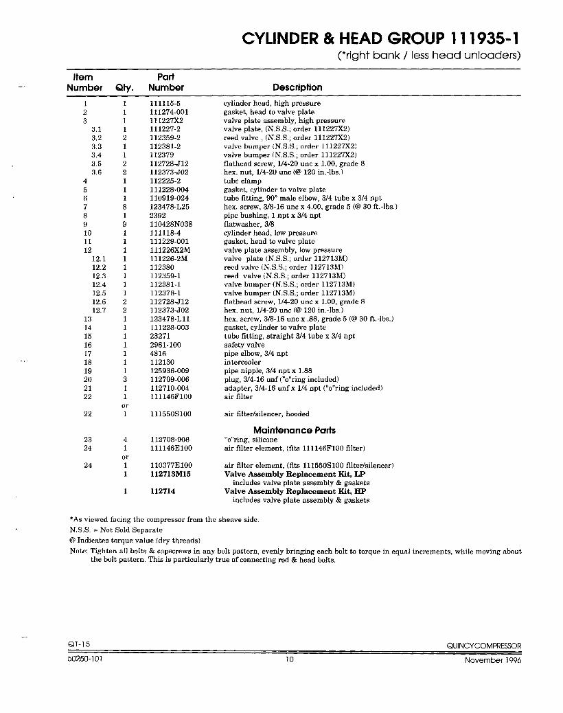
CYLINDER & HEAD GROUP 111935-1(*right bank / less head unloaders)
—[tern Part
Number Qty. Number Description
.—
123
3.13.23.33.43.53.6
456789101112
12.112.212.312.412,512.612.7
13141516171819202122
22
2324
24
11112112211181911111111221111111311
or1
41or11
1
111115-5111274-001111227X2111227-2112359-2112381-2112379112728-J12112373-J02112225-2111228-004110919-024123478-L252392110428NO38111118-4111229-001111226X2M111226-2M112380112359-1112381-1112378-1112728-J12112373-J02123478-L1l111228-003232712961-1004816112130125936-009112709-006112710-0041I1146F1OO
111550s100
112708-908111146E1OO
110377E1oO112713M15
112714
cylinder head, high pressuregasket, head to valve platevalve plate assembly, high pressurevalve plate, (NS.S.; order ll1227X2)reed valve , (N. S. S.; order 111227X2)valve bumper (N.SS.; order 111227X2)valve bumper (N. S.S.; order 111227X2)flathead screw, l/4-20 uncxl.OO, grade8hex. nut, l/4-20 unc(@120in.-lbs.)tube clampgasket, cylinder to valve platetube fitting, 90° male elbow, 314 tube x 314 npthex. screw, 3/8-16 unc x 4.00, grade 5 (6230 ft.-lbs.)pipe bushing, 1 npt x 314 nptflatwasher, 318cylinder head, low pressuregasket, head to valve platevalve plate assembly, low pressurevalve plate (N. S. S.; order l12713M)reed valve (N. S. S.; order 112713M)reed valve (N. S. S.; order 112713M)vaIvebumper (N. S.S.; order 112713M)valve bumper (N. S.S.; order 112713M)flathead screw, l/4-20 uncxl.OO, grade8hex. nut, l/4-20 unc(@120in,-lbs,)hex. screw, 3/8-16 unc x .88, grade 5 K@30 ft.-lbs.)gasket, cylinder to valve platetube fitting, straight 3/4 tube x 3/4 nptsafety valvepipe elbow, 314 nptintercoolerpipe nipple, 3/4 npt x 1.88plug, 3/4-16 unf (“o’’ring included)adapter, 3/4-16 unfx l/4npt(’’0’’ring included)air filter
air filter/silencer, hooded
Maintenance Parts“o’’ring, siliconeair fdterelement, (fita ll1146F100 filter)
air fikerelement, (fits l11550S100 filter/silencer)Valve Assembly Replacement Kit, LP
includes valve plate assembly & gasketsValve Assembly Replacement Kit, HP
includes valve plate assembly&gaskets
*As viewed facing the compressor from the sheave side.
N,S,S. =Not Sold Separate
@ Indicates torque value (dry threads)
Note: Tighten all bolts & capscrews in any bolt pattern, evenly bringing each bolt to torque in equal increments, while moving aboutthe bolt pattern. This is particularly true of connecting rod & head bolts.
QT-15 QUINCVCOMPREWR
50250-101 10 November 1996
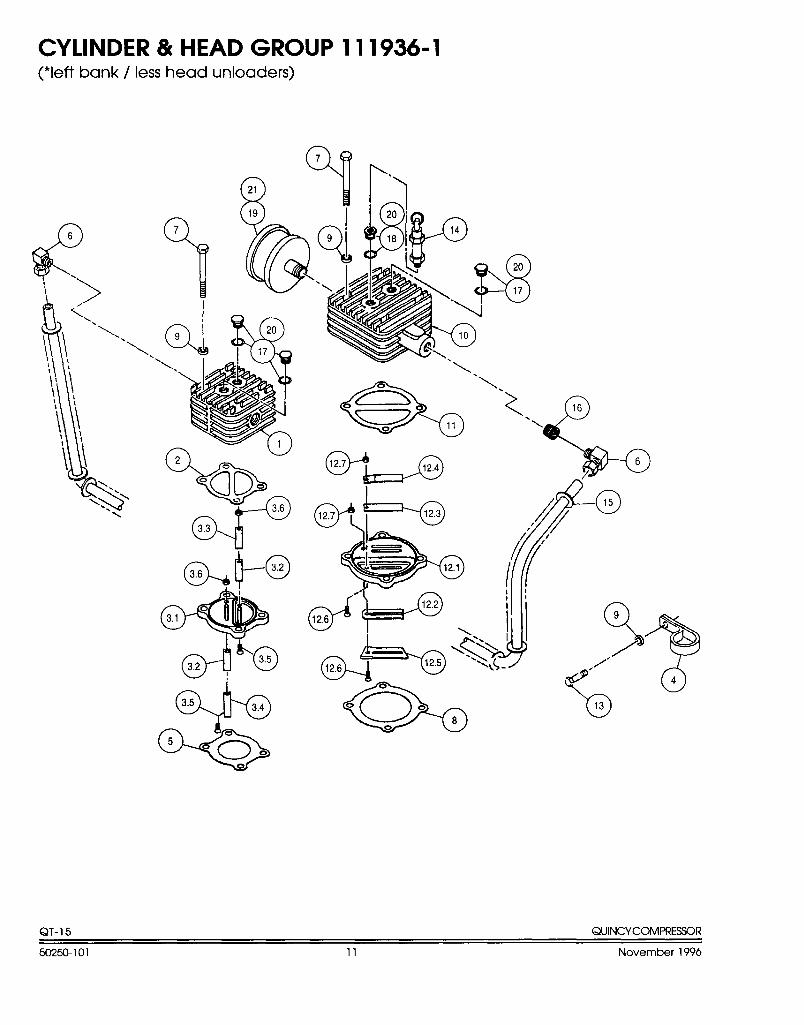
CYLINDER & HEAD GROUP 111936-1(*left bank / less head unloaders)
8
16
\
-Q!?&0
00
c.
3.6
3.3
u
*
%
9
/
Q’”
b
?!!?4
13
QT- 15 QUINCYCOMIWESSOR
50250101 11 November 1996
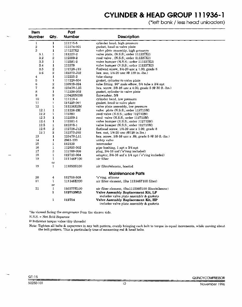
CYLINDER & HEAD GROUP 111936-1(*left bank / less head unloaders)
Item PartNumber Qty. Number Description
-.
.-
123
3.13.23.33.43.53.6
456789101112
12,112.212.312.412.512,612.7
13141516171819
19
2021
21
11112112211281911111111221111311
or1
41
or11
1
111115-5111274-001111227X2111227-2112359-2112381-2112379112728-J12112373-J02112225-2111228-004110919-024123478-L25111228-003110428NO38111118-4111229-001111226X2M111226-2M112380112359-1112381-1112378-1112728-J12112373-J02123478-L1l2961-100112129112825-002112709-006112710-004111146F1OO
111550s100
112708-908111146E1OO
110377E1oO112713M15
112714
cylinder head, high pressuregasket, head to valve platevalve plate assembly, high pressurevalve plate, (NS.S.; order ll1227X2)reed valve, (N. S. S.; order 111227X2)valve bumper (N. S,S.; order 111227X2)valve bumper (N. S.S.; order 111227X2)flathead screw, l/4-20 uncxl.OO, grade8hex. nut, l/4-20 unc(@120in.-lbs.)tube clampgasket, cylinder to valve platetube fitting, 90° male elbow, 3/4 tube x 3/4 npthex. screw, 3/8-16 unc x 4.00, grade 5 (C230 ft.-lbs. )gasket, cylinder to valve plateflatwasher,3/8cylinder head, low pressuregasket, head to valve platevalve plate assembly, low pressurevalve plate (N. S. S.; order l12713M)reed valve (N. SS.; order 112713M)reed valve (N. S,S.; order 112713M)valve bumper (N. S. S.; order 112713M)valve bumper (N. S.S.; order 112713M)flathead screw, l/4-20 uncx 1.00, grade8hex. nut, l/4-20 unc(@120in.lbs. )hex, screw, 3/8-16 unc x .88, grade 5 @30 ft,-lbs, )safety valveintercoolerpipe bushing, 1 npt x 3/4 nptplug,3/4-16unf (“o’’ringincluded)adapter, 3/4-16 unfx l/4npt(’’0’’ring included)air filter
air fdtedsilencer, hooded
Maintenance Parts“o’’ring, siliconeair filter element, (fits lll146F100tlter)
air tilter element, (fit.sll1550S100 fWer/silencer)Valve Assembly Replacement Kit, LP
includes valve plate assembly& gasketsValve Assembly Replacement Kit, HP
includes valve plate assembly & gaskets
*As viewed facing the compressor from the sheave side.
N.S.S. =Not Sold Separate
@ Indicates torque value (dry threads)
Note: Tighten all bolts & capscrews in any bolt pattern, evenly bringing each bolt to torque in equal increments, while moving aboutthe bolt pattern. This is particularly true of connecting rod & head bolts.
QT-15 QUINCYCOMPRESSOR
50250-101 12 November 1996
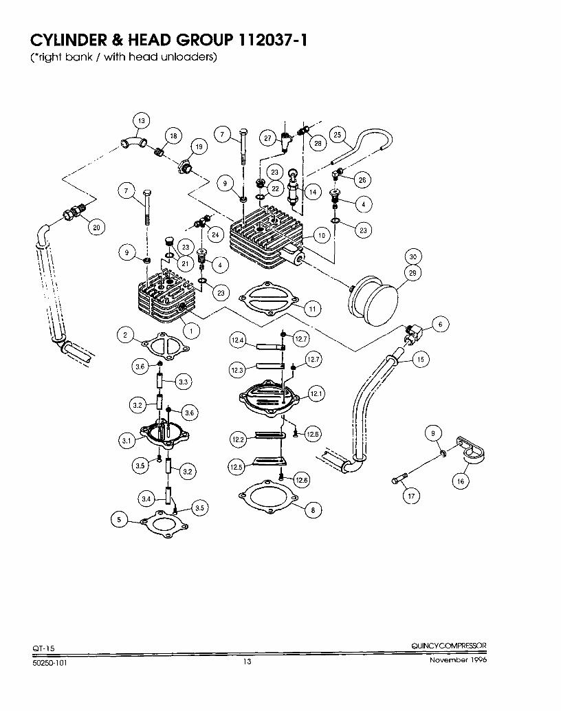
CYLINDER 8( HEAD GROUP 112037-1(*right bank / with head unloaders)
-~
‘$23/7’16
QT- 15 QuINCYCOMPRESSOR
50250-101 13 November 1996
—. —- .. ———..
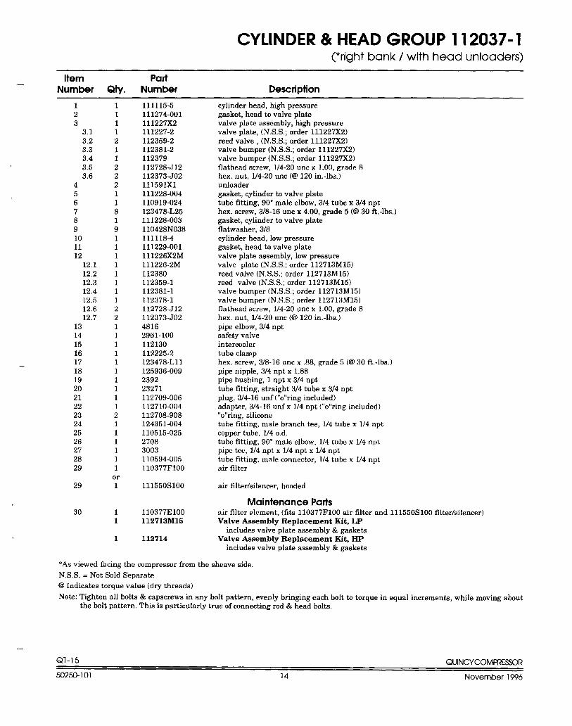
CYLINDER & HEAD GROUP 112037-1~right bank/ with head unloaders)
— Item PartNumber Qty. Number Description
—
123
3.13.23.33.43.53.6
456789101112
12.112.212.312.412.512.612.7
1314151617181920212223242526272829
29
30
111121122211819111111112211111111112111111
or1
11
1
111115-5111274-001111227X2111227-2112359-2112381-2112379112728-J12112373-J02111591X1111228-004110919-024123478-L25111228-003110428NO38111118-4111229-001111226X2M111226-2M112380112359-1112381-1112378-1112728-J12112373-J0248162961-100112130112225-2123478-L1l125936-009239223271112709-006112710-004112708-908124351-004110515-02527083003110594-005110377F1OO
111550s100
110377E1OO112713M15
112714
cylinder head, high pressuregasket, head to valve platevalve plate assembly, high pressurevalve plate, (N. S.S.; order 111227X2)reed valve , (N. S.S.; order 111227X2)valve bumper (N. S.S.; order 111227X2)valve bumper (N. S.S.; order 111227X2)flathead screw, 114-20 uncxl.OO, grade8hex. nut, l/4-20 unc (CO120 in.-lbs.)unloadergasket, cylinder to valve platetube fitting, 90° male elbow, 314 tube x 314 npthex. screw, 3/8-16 unc x 4.00, grade 5 (@30 ft.-lbs.)gasket, cylinder to valve plateflatwesher,3/8cylinder head, low pressuregasket, head to valve platevalve plate assembly, low pressurevalve plate (N. S. S.; order l12713M15)reed valve (N. SS.; order 112713M15)reed valve (N. S.S,; order 112713M15)valve bumper (N. S.S.; order 112713M15)valve bumper (N. S. S.; order 112713M15)flathead screw, 114-20 uncxl.OO, grade8hex. nut, l/4-20 unc(@120in.-lbs.)pipe elbow, 3/4 nptsafety valveintercoolertube clamphex. screw, 3/8-16 unc x ,88, grade 5 (@30 ft.-lbs.)pipe nipple, 3/4 npt x 1.88pipe bushing, 1 npt x 3/4 npttube fitting, straight 3/4 tube x 314 nptplug, 3/4-16 unf (“o’’ring included)adapter, 3/4-16 unfx l/4npt(’’0’’ring included)“o’’ring, siliconetube fitting, male branch tee, l/4tubexl/4nptcopper tube, l/40.d.tube fitting, 90 ° male elbow, l/4tubexl/4nptpipe tee, l/4nptx l/4nptxl/4npttube fitting, maleconnector, l/4tubexl/4nptair filter
air fiker/silencer, hooded
Maintenance Partsair filter element. (fits 110377F1OO airtilter and l11550S100 filter/silencer)Valve Assembly Replacement Kit, LP
includes valve plate assembly&gasketsValve Assembly Replacement Kit, HP
includes valve plate assembly& gaskets
*As viewed facing the compressor from the sheave side,
N.S.S. = Not Sold Separate
@ Indicates torque value (dry threads)
Note: Tighten all bolts & capscrews in any bolt pattern, evenly bringing each bolt to torque in equal increments, while moving aboutthe bolt pattern. This is particularly true of connecting rod & head bolts.
...
QT- 15 QUINCYCOMPRESSOR
50250-101 14 November 1996
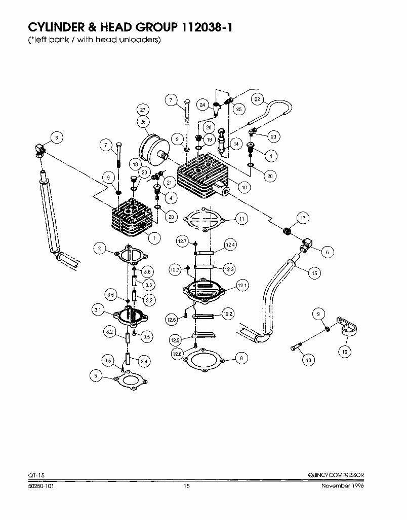
CYLINDER & HEAD GROUP 112038-1(*leftbank / with head unloaders)
QT- 15 QUINCYCOMPRESSOR
50250-101 15 November 1996
—.
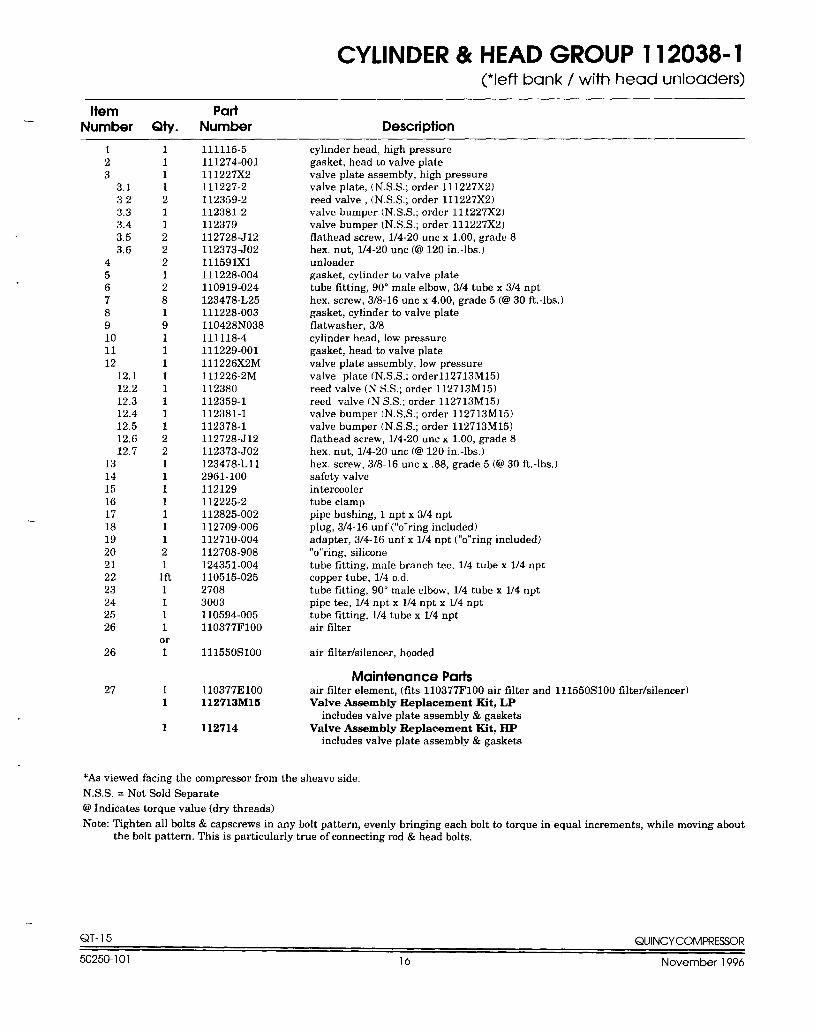
CYLINDER & HEAD GROUP 112038-1(*left bank / with head unloaders)
Item PartNumber Qty. Number Description
..
123
3,1323.33.43.53,6
456789101112
12.112.212.312.412.512.612,7
1314151617181920212223242526
26
27
1
111211222128191111111122111111121
lft1111
or1
11
1
111115-5111274-001111227X2111227-2112359-2112381-2112379112728J12112373-J02111591X1111228-004110919-024123478-L25111228-003110428NO38111118-4111229-001111226X2M111226-2M112380112359-1112381-1112378-1112728-J12112373-J02123478-L1l2961-100112129112225-2112825-002112709-006112710-004112708-908124351-004110515-02527083003110594-005110377F1oo
111550s100
110377E1OO112713M15
112714
cyhnderhead, high pressuregasket, head to valve platevalve plate assembly, high pressurevalve plate, (N. S.S.; order 111227X2)reed valve, (N. S,S.; order 111227X2)valve bumper (N. S.S.; order 111227X2)valve bumper [N. S.S.; order ll1227X2)tlathead screw, l/4-20 uncxl.OO, grade8hex, nut, l/4-20 unc(@120in.-lbs. )unloadergasket, cylinder to valve platetube fitting, 90 ° male elbow, 3/4tubex3/4npthex. screw, 3/8-16 unc x 4.00, grade 5 (CU30 ft.-lbs. )gasket, cylinder to valve plateflatwasher,3/8cylinder head, low pressuregasket, head to valve platevalve plate assembly, low pressurevalve plate (N. SS.; orderl12713M15)reed valve (N SS.; order 112713M15)reed valve (N S.S,; order 112713M15)valve bumper (N. S.S.; order 112713M15)valve bumper (N. SS.; order 112713M15)flathead screw, l/4-20 uncx 1.00, grade8hex. nut, 1/4-20 unc (63 120 in.-lbs.)hex. screw, 3/8-16 unc x .88, grade 5 (@ 30 ft. -lbs. )safety valveintercoolertube clamppipe bushing, lnptx3/4nptplug, 3/4-16 unf (“o’’ring included)adapter, 3/4-16 unf x 1/4 npt (“o’’ring included)“o’’ring, siliconetube fitting, midebrancb tee, l/4tubexl/4nptcopper tube, 1/4 o,d,tube titting, 90 ° male elbow, l/4tubexl/4nptpipe tee, l/4nptx l/4nptxl/4npttube fitting, l/4tubexl/4nptair filter
air tilter/silencer, hooded
Maintenance Partsairtilter element, (fits 110377F1OO air filter and 111550S100 filter/silencer)Valve Assembly Replacement Kit, LP
includes valve plate assembly& gasketsValve Assembly Replacement Kit, HP
includes valve plate assembly & gaskets
*As viewed facing the compressor from the sheave side.
N.S.S. =Not Sold Separate
@ Indicates torque value (dry threads)
Note: Tighten all bolts & capscrews in any bolt pattern, evenly bringing each bolt to torque in equal increments, while moving aboutthe bolt pattern. This is particularly true of connecting rod & head bolts.
QT-15 QUINCYCOMFI?ESSOR
50250-101 16 November 1996
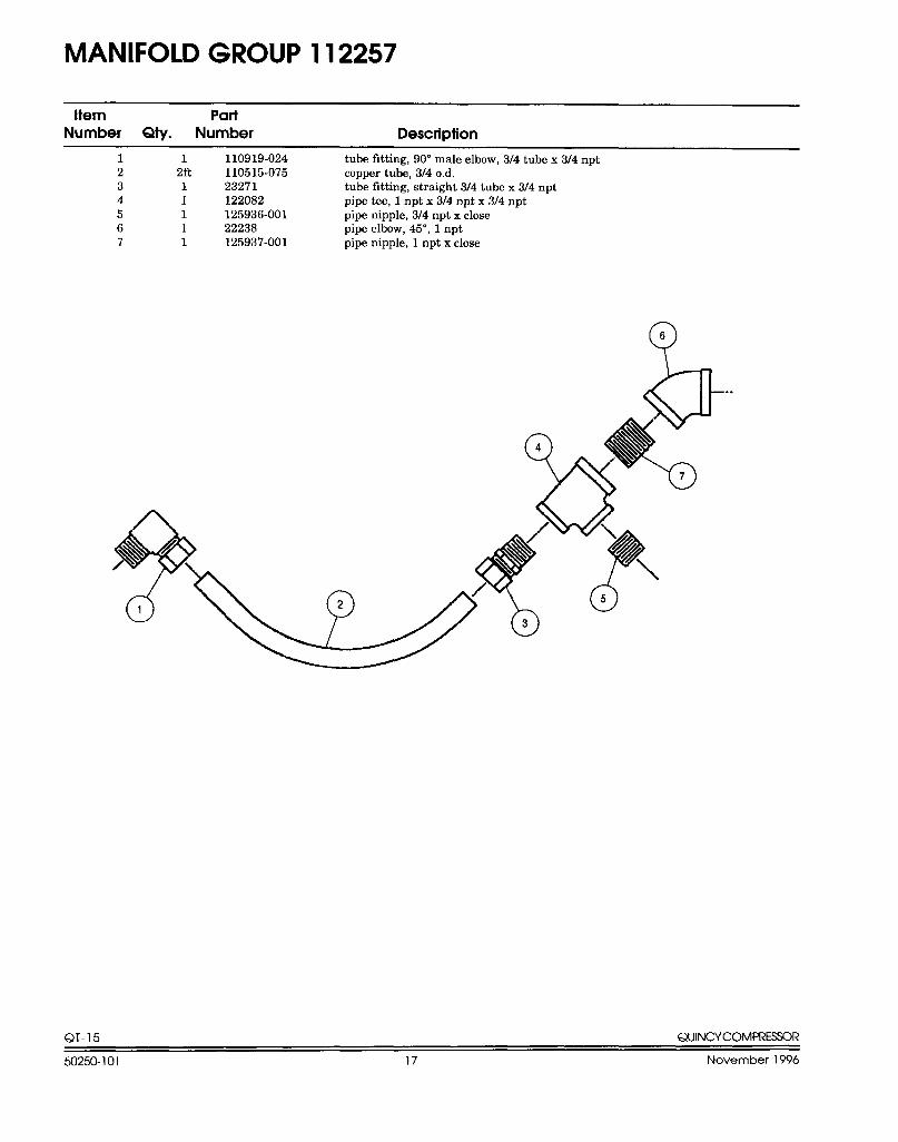
MANIFOLD GROUP 112257
Hem PariNumber Qty. Number Description
1 1 110919-024 tube fitting, 90” male elbow, 3/4 tube x 314 npt2 2ft 110515-075 copper tube, 3/4 o.d.3 1 23271 tube fitting, straight 314 tube x 314 npt4 1 122082 pipe tee, 1 npt x 3J4 npt x 314 npt5 1 125936-001 pipe nipple, 3/4 npt x close6 1 22238 pipe elbow, 45°, 1 npt7 1 125937-001 pipe nipple, 1 npt x close
Q6
QT-15 QUINCYCOMFI?ESSOR
50250-101 17 November 1996
—. -—. —.
--
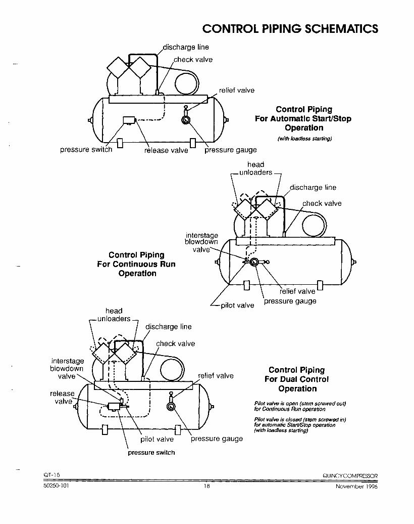
CONTROL PIPING SCHEMATICS,discharge line
relief valve
For
/pressure switch pressure gauge
Control PipingAutomatic Start/Stop
Operation(with badless starting)
Control PipingFor Continuous Run
Operation
head
head
r
unloaders
7 ~scharge line
valveControl Piping
For Dual ControlOperation
Pilot Valrn is open (stem screwed out)for Continuous Run operation
Pilot M/m is closed (stem screwed in)for automatic Start@top operation(with badass starting)
\pilot valve pressure gauge
pressure switch
—-QT-15 QUINCYCOMPRESSOR
50250-101 18 November 1996
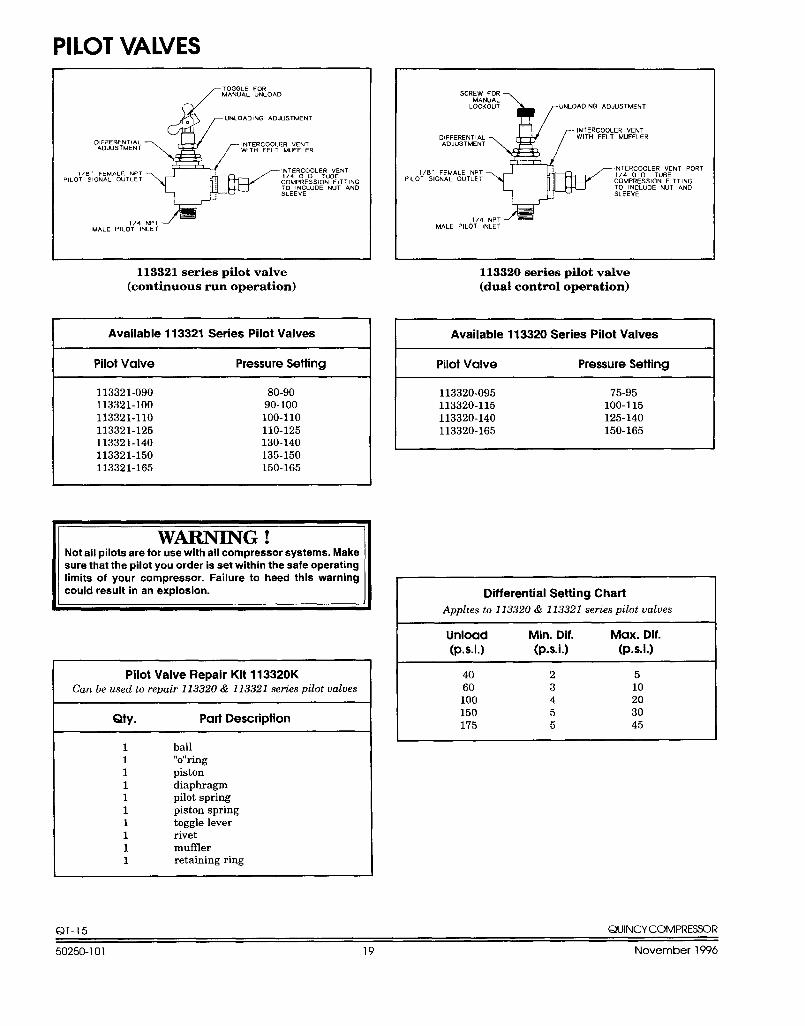
PILOT VALVES
TOGGLE FOR
6
MANUAL UNLOAD
UNLOADING ADJuSTMENT.
DIFFERENTIALAOdUSTMENT
[
lNTERCOOLER VENTWITH FELT MUFFLER
1/8 FEMALE NPT -, \~,T4EROCODOLE;UV:N T
PILOT SIGNAL OUTLET COMPRESSION FITTINGTO lNCLUOE NUT AND5LEEVE
.;
1/4 NPT 1MALE PILoT INLET
113321 series pilot valve(continuous run operation)
Available 113321 Series Pilot Valves IPilot Valve Pressure Setting
113321-090 80-90113321-100 90-100113321-110 100-110113321-125 110-125113321-140 130-140113321-150 135-150113321-165 150-165
II WMNING !Not all pilots are for use with all compressor systems. Makesure that the pilot you order is set within the safe operatinglimits of your compressor. Failure to heed this warningcould result in an explosion.
II
Pilot Valve Repair Kit 113320KCan be used to repair 113320& 113321 series pilot valves
Qty. Part Description
1111111111
ball“o’’ringpistondiaphragmpilot springpiston springtoggle leverrivetmufflerretaining ring
SCREW FOR
$
MANUALLOCKOUT uNLOADING ADJUSTMENT
f
INTERCOOLER VENTDIFFERENTIAL WITH FELT MLJFFLERADJuSTMENT
1/8. FEMALE NPTINTERCOOLER VENT PORT
PILOT SIGNAL OUTLET1/4 O D TuBECOMPRESS1ON FITTINGTO INCLUDE NUT ANDSLEEVE..
——
1/4 NPT =MALE PILOT INLET
113320 series pilot valve(dual control operation)
Available 113320 Series Pilot Valves 1
Pilot Valve Pressure Setthg
113320-095 7’5-95113320-115 100-115113320-140 125-140113320-165 150-165
Differential Setting Chart
Apphes to 113320& 113321 series pilot valves
Unload Min. Dif. Max. Dif.(p.s. i.) (p.s. i.) (p.s. i.)
40 2 560 3 10100 4 20150 5 30175 5 45
QT- 15 QUINCYCOMPRE3SOR
50250-101 19 November 1996
—. ——-..
—
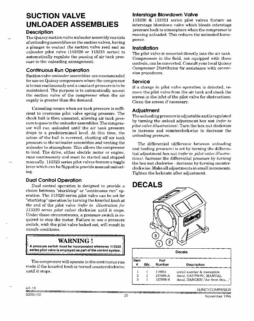
SUCTION VALVEUNLOADER ASSEMBLIESDescriptionThe Quincy suction valve unloader assembly consistsof unloading assemblies on the suction valves, havinga plunger to contact the suction valve reed and anunloader pilot valve (113320 or 113321 series) toautomatically regulate the passing of air tank pres-sure to the unloading arrangement.
Continuous Run OperationSuction valve unloader assemblies are recommendedfor use on Quincy compressors where the compressoris to run continuously and a constant pressure is to bemaintained. The purpose is to automatically unseatthe suction valve of the compressor when the airsupply is greater than the demand.
Unloading occurs when air tank pressure is suffi-cient to overcome pilot valve spring pressure. Thecheck ball is then unseated, allowing air tank pres-sure to pass to the unloader assemblies. The compres-sor will run unloaded until the air tank pressuredrops to a predetermined level. At this time, theaction of the ball is reversed, shutting off air tankpressure to the unloader assemblies and venting theunloader to atmosphere. This allows the compressorto load. The drive, either electric motor or engine,runs continuously and must be started and stoppedmanually, 113321 series pilot valves feature a togglelever which can be flipped to provide manual unload-ing.
Dual Control OperationDual control operation is designed to provide a
choice between “startistop” or “continuous run” op-eration. The 113320 series pilot valve can be set for“startistop” operation by turning the knurled knob atthe end of the pilot valve (refer to illustration j%r113320 series pilot valve) clockwise until it stops.Under these circumstances, a pressure switch is re-quired to stop the motor. Failure to use a pressureswitch, with the pilot valve locked out, will result inunsafe conditions.
A pressure switch must be incorporated whenever 113320series pilot valve is employed as part of the control system.
The compressor will operate in the continuous runmode if the knurled knob is turned counterclockwiseuntil it stops.
QT-15
Interstate Blowdown Valve113320 & 113321 series pilot valves feature aninterstage blowdown valve which bleeds interstagepressure back to atmosphere when the compressor isrunning unloaded. This reduces the unloaded horse-power.
InstallationThe pilot valve is mounted directly into the air tank.Compressors in the field, not equipped with thesecontrols, can be converted. Consult your local QuincyCompressor Distributor for assistance with conver-sion procedures.
ServiceIf a change in pilot valve operation is detected, re-move the pilot valve from the air tank and check thescreen in the inlet of the pilot valve for obstructions.Clean the screen if necessary.
AdjustmentThe unloading pressure is adjustable and is regulatedby turning the unload adjustment hex nut (refer topilot valve illustrations). Turn the hex nut clockwiseto increase and counterclockwise to decrease theunloading pressure.
The differential (difference between unloadingand loading pressure) is set by turning the differen-tial adjustment hex nut (refer to pilot valve illustra-tions). Increase the differential pressure by turningthe hex nut clockwise - decrease by turning counter-clockwise. Make all adjustments in small increments.Tighten the locknuts after adjustment.
DECALS
Decals
Item Part# Qty. Number Description
11 110831 serial number & nameplate21 127889-A decal, CAUTION!, MANUAL31 127889-B decal, DANGER!,’’Air from this,,,.’”
O( JINCYCOMPRESSOR—-. .
50250-101 20 November 1996
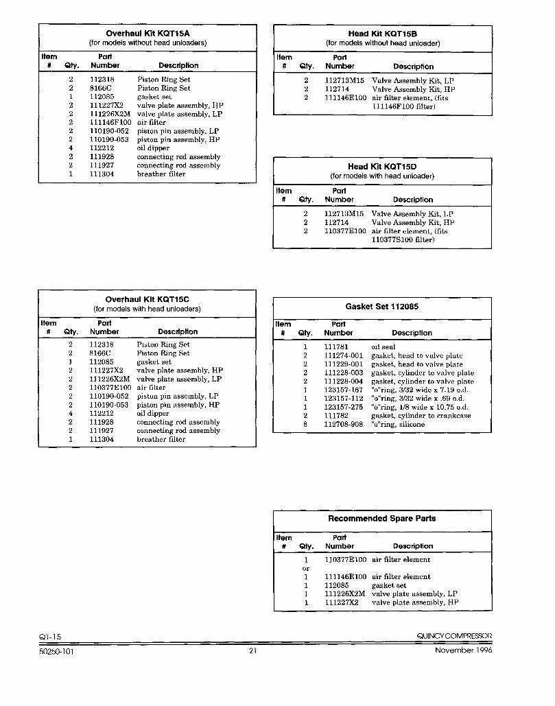
Overhaul Kit KQT15A(for models without head unloaders)
tern Part# Qty. Number Description
2 112318 Piston Ring Set2 8166C Piston Ring Set1 112085 gasket set2 111227X2 valve plate assembly, HP2 111226X2M valve plate assembly, LP2 111146F1OO air filter2 110190-052 piston pinassembly, LP2 110190-053 piston pinassembly, HP4 112212 oil dipper2 111928 connecting rod assembly2 111927 connecting rod assembly1 111304 breather filter
Overhaul Kit KQT15C(for models with head unloaders)
tern Part# Qty. Number Description
2 112318 Piston Ring Set2 8166C Piston Ring Set1 112085 gasket set2 111227X2 valve plate assembly, HP2 111226X2M valve plate assembly, LP2 110377E1OO air filter2 110190-052 piston pinassembly, LP2 110190-053 piston pinassembly, HP4 112212 oil dipper2 111928 connecting rod assembly2 111927 connecting rod assembly1 111304 breather filter
Head Kit KQT15B(tor models without head unloader)
Item Part# Qty. Number Description
2 112713M15 Valve Assembly Kit, LP2 112714 Valve Assembly Kit, HP2 111146E1OO air filter element, (fits
111146F1OO filter)
Head Kit KQT15D(for models with head unloader)
Item Pati# Qty. Number Description
2 112713M15 Valve Assembly Kit, LP2 112714 Valve Assembly Kit, HP2 110377E1OO air filter element, (fits
110377S100 filter)
Gasket Set 112085
Item Part# Qty. Number Description
1222211128
111781111274-001111229-001111228-003111228-004123157-167123157-112123157-275111782112708-908
oil sealgasket, head to valve plategasket, head to valve plategasket, cylinder to valve plategasket, cylinder to valve plate“o’’ring, 3/32 wide x 7.19 o.d.“o’’ring, 3132 wide x .69 o.d.“o’’ring, U8 wide x 10.75 o.d.gasket, cylinder to crankcase“o’’ring, silicone
1 110377E1OO air filter elementor1 111 146E1OO air filter element1 112085 gasket set1 111226X2M valve plate assembly, LP1 111227X2 valve plate assembly, HP
QT-15 QUINCYCOMPRESSOR
50250-101 21 November 1996
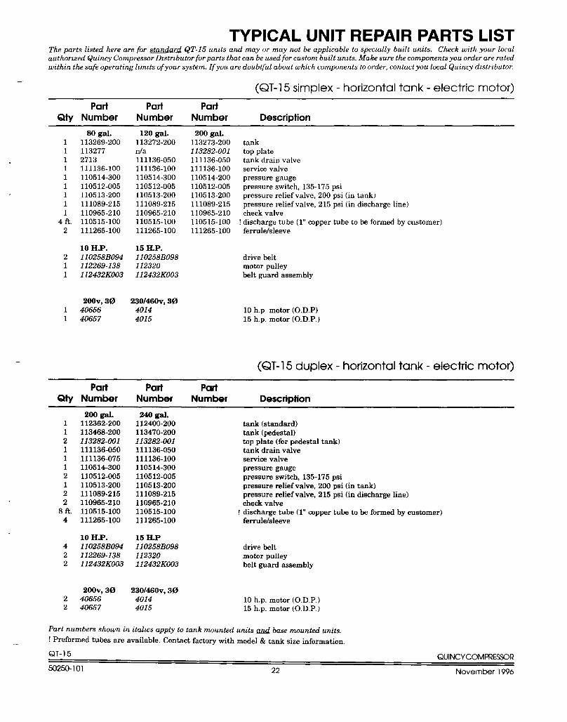
TYPICAL UNIT REPAIR PARTS LISTThe parts listed here are for standard QT-15 uruts and may m may not be applicable to specially built units. Check with your localauthorized Quimy Compressor Dwtrlbutor for parts that can be used for custom built uruts. Make sure the components you order are ratedwithin the safe operating hmlts of your system. If you are doubtful about which components to order, contact you local Quincy distributor.
(QT-15 simplex - horizontal tank - electric motor)
Part Part PartQty Number Number Number Description
-.
111111111
4 fi.2
211
11
80 gal.113269-2001132772713111136-100110514-300110512-005110513-200111089-215110965-210110515-100111265-100
10 H.P.110258BO94112269-138112432KO03
200v, 304065640657
120 gal.113272-200da111136-050111136-100110514-300110512-005110513-200111089-215110965-210110515-100111265-100
15 H.P.I10258BO98112320112432KO03
230AOOv,3040144015
200 gal.113273-200113282-001111136-050111136-100110514-200110512-005110513-200111089-215110965-210110515-100111265-100
tanktop platetank drain valveservice valvepressure gaugepressure switch, 135-175 psipressure relief valve, 200 psi (in tank)pressure relief valve, 215 psi (in discharge line)check valve
! discharge tube (l” capper tube to be formed by customer)ferrulekileeve
drive beltmotor pulleybelt guard assembly
10h.p motor (O.D.P)15 hp. motor (0. D. P.)
(QT-15 duplex - horizontal tank - electric motor)
Part Part PartQty Number Number Number Description
200 gal. 240 gal.1 112362-200 112400-200 tank (standard)1 113468-200 113470-200 tank (pedestal)2 113282-001 113282-001 top plate (for pedestal tank)1 111136-050 111136-050 tank drain valve1 111136-075 111136-100 service valve1 110514-300 110514-3002
pressure gauge110512-005 110512-005
1 110513-200pressure switch, 135-175 psi
110513-2002 111089-215
pressure relief valve, 200 psi (in tank)111089-215
2pressure relief valve, 215 psi (in discharge line)
110965-210 110965-210 check valve8tt. 110515-100 110515-100 ! discharge tube (l” copper tube to be formed bycust.omer)
4 111265-100 111265-100 ferrule/sleeve
10 H.P. 15 H.P4 110258BO94 110258BO98 drive belt2 112269-138 112320 motor pulley2 112432KO03 112432KO03 belt guard assembly
200v, 30 230/460v,302 40656 4014 10 hp. motor (0. D, P.)2 40657 4015 15 hp. motor (0. D. P.)
Part numbers shown in itahcs apply to tank mounted units & base mounted units.
! Preformed tubes are available. Contact factory with model & tank size information,—
QT-15 QUINCYCOMPRESSC)R
50250-101 22 November 1996
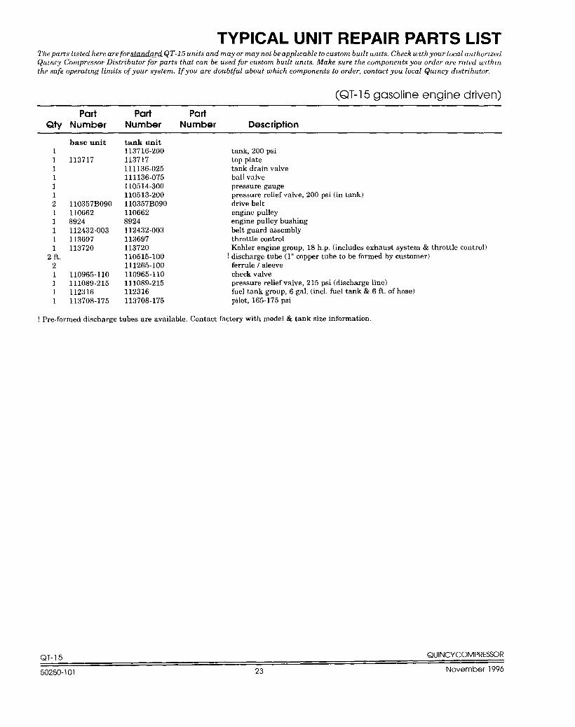
TYPICAL UNIT REPAIR PARTS LISTTheparts hsted here are forstandard QT-15 units and mayor may not be apphcable to custom budt uruts, Check wtthyour local authorizedQumcy Compressor Distributor for parts that can be used for custom budt umts. Make sure the components you order are rated u,lth,nthe safe operating limits of your system. If you are doubtful about which components to order, contact you local @mcy d~stributor.
(QT-15 gasoline engine driven)
Part Part PartQty Number Number Number Description
111111211111
2 ft.21111
base unit
113717
110357BO9O1106628924112432-003113697113720
110965-110111089-215112316113708-175
tank unit113716-200113717111136-025111136-075110514-300110513-200110357BO9O1106628924112432-003113697113720110515-100111265-100110965-110111089-215112316113708-175
tank, 200 psitop platetank drain valveball valvepressure gaugepressure relief valve, 200 psi (in tank)drive beltengine pulleyengine pulley bushingbelt guard assemblythrottle controlKohler engine group, 18 hp. (includes exhaust system & throttle control)
! discharge tube ( 1“ copper tube to be formed by customer)ferrule / sleevecheck valvepressure relief valve, 215 psi (discharge line)fuel tank group, 6 gal, (incl. fuel tank & 6 ft. of hose)pilot, 165-175 psi
! Pre-formed discharge tubes are available. Contact factory with model & tank size information.
QT- 15 QUINCYCOMPI?ES!XIR
50250-101 23 November 1996
NATIONWIDESALES & SERVICE
Quincy Service is always near.There are Authorized Quincy Distributors locatedthroughout the United States & Canada that stock
genuine Quincy parts& accessories for a widerange of Quincy products.
Quincy Service specialists are factory trained andwill help keep you in business. Call for Authorized
Quincy Service.
For reciprocating productsand natural gas engine driven
helical screw products:ca// 1-217-222-7700
or fax requests to 1-800-219-9126
For all other helical screw products:ca// 1-334-937-5900
or fax requests to 1-800-219-9131
Accept No Whtutes
QuincyCompressor Division
Coltec Industries
@