Embed Size (px)
Citation preview
User's GuideSLUUB24–June 2014
Quickstart Guide for Gauge Development Kit
The Gauge Development Kit (GDK) is a complete evaluation system for any single-cell fuel gaugedeveloped by Texas Instruments Incorporated. The GDK is a single printed circuit board (PCB) equippedwith a programmable load, programmable charger, and an integrated EV2400 for PC interaction viaBattery Management Studio. A USB PC cable and an external 6-V power supply capable of supplying atleast 2.5-A are not included with the GDK, but are necessary for full functionality. The 6-V power supplycan be provided through test points or a dc barrel jack on the PCB. The latest version of BatteryManagement Studio (bqStudio) should be downloaded from ti.com and installed to communicate with andcontrol the GDK. Once the GDK is powered and connected to a PC via USB cable, bqStudio allows theuser to do the following:• Read the connected fuel gauge data registers• Configure the connected fuel gauge• Discharge the connected battery• Charge the connected battery• Log cycling data for evaluation• Automated Learning Cycle(s)• Evaluate the overall functionality of the connected fuel gauge solution under different charge and
discharge conditions
Contents1 Overview ...................................................................................................................... 22 Software Setup............................................................................................................... 23 Hardware Setup.............................................................................................................. 34 Using the GDK ............................................................................................................... 45 GDK and DVC Fuel Gauge Configuration................................................................................ 66 Related Documentation from Texas Instruments........................................................................ 67 Revision History.............................................................................................................. 6
List of Figures
1 GDK Hardware Setup ....................................................................................................... 32 bqStudio Default GDK Perspective........................................................................................ 43 GDK Plug-in .................................................................................................................. 54 GDK and DVC Fuel Gauge Hardware Connections .................................................................... 6
1SLUUB24–June 2014 Quickstart Guide for Gauge Development KitSubmit Documentation Feedback
Copyright © 2014, Texas Instruments Incorporated
Overview www.ti.com
1 OverviewBy using the GDK, only a few simple steps are needed to begin fuel gauge evaluation. First, the BatteryManagement Studio (bqStudio) software suite should be downloaded to the PC connecting to the GDK.Second, the proper hardware connections need to be made between the GDK, a PC running bqStudio,and the EVM under evaluation. Finally, use bqStudio to configure the connected fuel gauge according toapplication specifications.
2 Software SetupThe PC connecting to the GDK is required to be running Battery Management Studio (bqStudio). Thelatest version of bqStudio can be found atwww.ti.com/tool/bq27gdk000evm.
Use the following steps to install bqStudio:1. Ensure that the GDK board is not connected to the PC via the USB cable before starting the
procedure.2. Open the archive containing the installation package, and copy its contents into a temporary directory.3. Open the software file that was downloaded from the TI website.4. Follow the instructions on the screen until the software installation is complete.5. Before starting bqStudio, connect the GDK to the PC with the USB cable.6. The EV2400 hardware will be detected and drivers will automatically be installed. No separate driver
installation is required.
2 Quickstart Guide for Gauge Development Kit SLUUB24–June 2014Submit Documentation Feedback
Copyright © 2014, Texas Instruments Incorporated
www.ti.com Hardware Setup
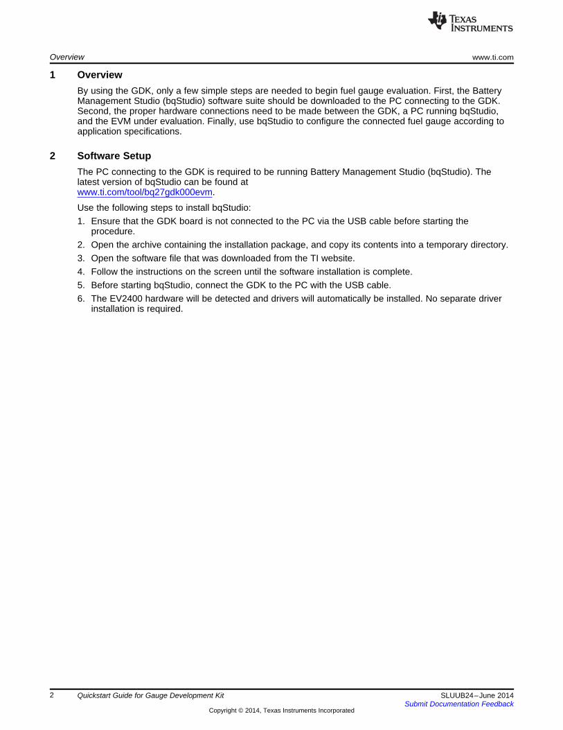
3 Hardware SetupThe GDK requires a few hardware connections before gauge evaluation can begin. All the connectionscan be seen in Figure 1.
Figure 1. GDK Hardware Setup
As seen in Figure 1, the GDK requires the following hardware setup:1. Connect external power to J3 or the corresponding test points (TP18: 6-V plug and TP39: PGND) on
the GDK. The external power should be able to supply 6 V at 2.5 A.2. Connect USB power/communication from the PC running bqStudio to J2 on the GDK.3. Connect the external load/charge connectors of the EVM to the External Load+/Charger+ (J4) and
External Load–/Charger– (J8) connectors of the GDK.
NOTE: If using a Dynamic Voltage Correlation (DVC) fuel gauge, the External Load+/Charger+ (J4)and External Load–/Charger– (J8) connectors of the GDK should be connected directly tothe battery. See Section 5, GDK and DVC Fuel Gauge Configuration, for more details.
4. Connect the external I2C bus of the EVM to the external I2C (J13) connector of the GDK.5. Connect the battery to the external EVM. The battery should be connected to the external EVM and
not the GDK board.
NOTE: See the GDK User’s Guide (SLUUAO1) for more details on the options of the GDKconfiguration.
3SLUUB24–June 2014 Quickstart Guide for Gauge Development KitSubmit Documentation Feedback
Copyright © 2014, Texas Instruments Incorporated
Using the GDK www.ti.com
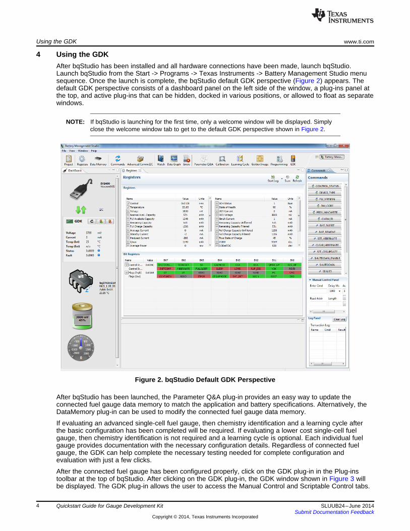
4 Using the GDKAfter bqStudio has been installed and all hardware connections have been made, launch bqStudio.Launch bqStudio from the Start -> Programs -> Texas Instruments -> Battery Management Studio menusequence. Once the launch is complete, the bqStudio default GDK perspective (Figure 2) appears. Thedefault GDK perspective consists of a dashboard panel on the left side of the window, a plug-ins panel atthe top, and active plug-ins that can be hidden, docked in various positions, or allowed to float as separatewindows.
NOTE: If bqStudio is launching for the first time, only a welcome window will be displayed. Simplyclose the welcome window tab to get to the default GDK perspective shown in Figure 2.
Figure 2. bqStudio Default GDK Perspective
After bqStudio has been launched, the Parameter Q&A plug-in provides an easy way to update theconnected fuel gauge data memory to match the application and battery specifications. Alternatively, theDataMemory plug-in can be used to modify the connected fuel gauge data memory.
If evaluating an advanced single-cell fuel gauge, then chemistry identification and a learning cycle afterthe basic configuration has been completed will be required. If evaluating a lower cost single-cell fuelgauge, then chemistry identification is not required and a learning cycle is optional. Each individual fuelgauge provides documentation with the necessary configuration details. Regardless of connected fuelgauge, the GDK can help complete the necessary testing needed for complete configuration andevaluation with just a few clicks.
After the connected fuel gauge has been configured properly, click on the GDK plug-in in the Plug-instoolbar at the top of bqStudio. After clicking on the GDK plug-in, the GDK window shown in Figure 3 willbe displayed. The GDK plug-in allows the user to access the Manual Control and Scriptable Control tabs.
4 Quickstart Guide for Gauge Development Kit SLUUB24–June 2014Submit Documentation Feedback
Copyright © 2014, Texas Instruments Incorporated

www.ti.com Using the GDK
Figure 3. GDK Plug-in
To begin a quick charge, complete the following under the Charge Control panel in the GDK Plug-inManual Control tab:1. Enter the Charge Voltage2. Enter the Charge Current3. Select a charge termination method4. Fill in the value for the corresponding charge termination method5. Click the Start button in the Charge Control panel
To begin a quick discharge, complete the following under the Discharge Control panel in the GDK Plug-inManual Control tab:1. Choose the discharge mode (constant current, constant power, or pulsed load)2. Fill in the corresponding information for the selected discharge mode3. Select the discharge termination method4. Fill in the value for the corresponding discharge termination method5. Click the Start button in the Discharge Control panel
For more details concerning the charge, discharge, and scriptable control offered in bqStudio when usingthe GDK, please see the GDK User’s Guide (SLUUAO1).
5SLUUB24–June 2014 Quickstart Guide for Gauge Development KitSubmit Documentation Feedback
Copyright © 2014, Texas Instruments Incorporated

GDK and DVC Fuel Gauge Configuration www.ti.com
5 GDK and DVC Fuel Gauge ConfigurationWhen using the GDK with a DVC fuel gauge there should be no current flowing on the lines connectingthe DVC fuel gauge to the battery. Therefore, the External Load+/Charger+ (J4) and ExternalLoad–/Charger– (J8) connectors of the GDK should be connected directly to the battery under test. Then,a Kelvin connection can be made from the battery terminals to the Pack+ and Pack– connectors on theDVC fuel gauge. See Figure 4 for DVC connection example.
Figure 4. GDK and DVC Fuel Gauge Hardware Connections
6 Related Documentation from Texas InstrumentsTo obtain a copy of any of the following TI documents, call the Texas Instruments Literature ResponseCenter at (800) 477-8924 or the Product Information Center (PIC) at (972) 644-5580. When ordering,identify this document by its title and literature number. Updated documents also can be obtained throughthe TI Web site at www.ti.com.1. Gauge Development Kit User's Guide (SLUUAO1)
7 Revision History
Version Change Date Description— June 2014 Initial Release
6 Quickstart Guide for Gauge Development Kit SLUUB24–June 2014Submit Documentation Feedback
Copyright © 2014, Texas Instruments Incorporated

IMPORTANT NOTICE
Texas Instruments Incorporated and its subsidiaries (TI) reserve the right to make corrections, enhancements, improvements and otherchanges to its semiconductor products and services per JESD46, latest issue, and to discontinue any product or service per JESD48, latestissue. Buyers should obtain the latest relevant information before placing orders and should verify that such information is current andcomplete. All semiconductor products (also referred to herein as “components”) are sold subject to TI’s terms and conditions of salesupplied at the time of order acknowledgment.TI warrants performance of its components to the specifications applicable at the time of sale, in accordance with the warranty in TI’s termsand conditions of sale of semiconductor products. Testing and other quality control techniques are used to the extent TI deems necessaryto support this warranty. Except where mandated by applicable law, testing of all parameters of each component is not necessarilyperformed.TI assumes no liability for applications assistance or the design of Buyers’ products. Buyers are responsible for their products andapplications using TI components. To minimize the risks associated with Buyers’ products and applications, Buyers should provideadequate design and operating safeguards.TI does not warrant or represent that any license, either express or implied, is granted under any patent right, copyright, mask work right, orother intellectual property right relating to any combination, machine, or process in which TI components or services are used. Informationpublished by TI regarding third-party products or services does not constitute a license to use such products or services or a warranty orendorsement thereof. Use of such information may require a license from a third party under the patents or other intellectual property of thethird party, or a license from TI under the patents or other intellectual property of TI.Reproduction of significant portions of TI information in TI data books or data sheets is permissible only if reproduction is without alterationand is accompanied by all associated warranties, conditions, limitations, and notices. TI is not responsible or liable for such altereddocumentation. Information of third parties may be subject to additional restrictions.Resale of TI components or services with statements different from or beyond the parameters stated by TI for that component or servicevoids all express and any implied warranties for the associated TI component or service and is an unfair and deceptive business practice.TI is not responsible or liable for any such statements.Buyer acknowledges and agrees that it is solely responsible for compliance with all legal, regulatory and safety-related requirementsconcerning its products, and any use of TI components in its applications, notwithstanding any applications-related information or supportthat may be provided by TI. Buyer represents and agrees that it has all the necessary expertise to create and implement safeguards whichanticipate dangerous consequences of failures, monitor failures and their consequences, lessen the likelihood of failures that might causeharm and take appropriate remedial actions. Buyer will fully indemnify TI and its representatives against any damages arising out of the useof any TI components in safety-critical applications.In some cases, TI components may be promoted specifically to facilitate safety-related applications. With such components, TI’s goal is tohelp enable customers to design and create their own end-product solutions that meet applicable functional safety standards andrequirements. Nonetheless, such components are subject to these terms.No TI components are authorized for use in FDA Class III (or similar life-critical medical equipment) unless authorized officers of the partieshave executed a special agreement specifically governing such use.Only those TI components which TI has specifically designated as military grade or “enhanced plastic” are designed and intended for use inmilitary/aerospace applications or environments. Buyer acknowledges and agrees that any military or aerospace use of TI componentswhich have not been so designated is solely at the Buyer's risk, and that Buyer is solely responsible for compliance with all legal andregulatory requirements in connection with such use.TI has specifically designated certain components as meeting ISO/TS16949 requirements, mainly for automotive use. In any case of use ofnon-designated products, TI will not be responsible for any failure to meet ISO/TS16949.
Products ApplicationsAudio www.ti.com/audio Automotive and Transportation www.ti.com/automotiveAmplifiers amplifier.ti.com Communications and Telecom www.ti.com/communicationsData Converters dataconverter.ti.com Computers and Peripherals www.ti.com/computersDLP® Products www.dlp.com Consumer Electronics www.ti.com/consumer-appsDSP dsp.ti.com Energy and Lighting www.ti.com/energyClocks and Timers www.ti.com/clocks Industrial www.ti.com/industrialInterface interface.ti.com Medical www.ti.com/medicalLogic logic.ti.com Security www.ti.com/securityPower Mgmt power.ti.com Space, Avionics and Defense www.ti.com/space-avionics-defenseMicrocontrollers microcontroller.ti.com Video and Imaging www.ti.com/videoRFID www.ti-rfid.comOMAP Applications Processors www.ti.com/omap TI E2E Community e2e.ti.comWireless Connectivity www.ti.com/wirelessconnectivity
Mailing Address: Texas Instruments, Post Office Box 655303, Dallas, Texas 75265Copyright © 2014, Texas Instruments Incorporated

![MAXPROLOGIC FPGA DEVELOPMENT SYSTEM Data Sheet€¦ · J4-6 XIO8_5 102 XIO8[5] J4-7 XIO8_6 105 XIO8[6] J4-8 XIO8_7 106 XIO8[7] J4-9 GND NC NC J4-10 GND NC NC Connector-Pin # Net Name](https://img.pdfslide.us/doc/110x75/609406a89a61bb3a6e6a0473/maxprologic-fpga-development-system-data-sheet-j4-6-xio85-102-xio85-j4-7-xio86.jpg)