Embed Size (px)
Citation preview
1
Bend-Tech Quick Start
Training Class 3 (SE Advanced)-----------------------------------------------------------------------------------------------------------------------------------
i. Things To Know
• This class worksheet is designed to walk the user through the Bend-Tech SE
product and specifics on our XYZ Designer, Multiple Dies per Part, Reverse
Design, Rotation Settings, Bend Order (in depth including flips), Pricing,
Importing .stp/.igs/.dxf, and Nesting. As you go through this class, later
procedures will assume that you understand all earlier procedures. Because of
this, it is very important that you carefully step through this guide, understanding
everything along the way.
---------------------------------------------------------------------------------------
ii. Getting Started
1) General Issues
• For some users, the setup process can be confusing. We are very aware that many
of our customers are better at fabricating in the shop or garage than they are at
operating computers. And that's OK!
WE'RE HERE TO HELP YOU!
• While this Class Guide has its own instructions to meet its own goals in teaching
you the basics to your Bend-Tech software, the over-the-phone training class is
2
subject to change according to the needs of the customer. With that being said, the
time spent on the phone for this class is set to a THIRTY MINUTE time slot, so we
might not be able to accommodate OUR whole agenda if we're taking a lot of time
on a certain question or concept. However, the manner in which this thirty
minutes is spent is entirely up to you!
---------------------------------------------------------------------------------------
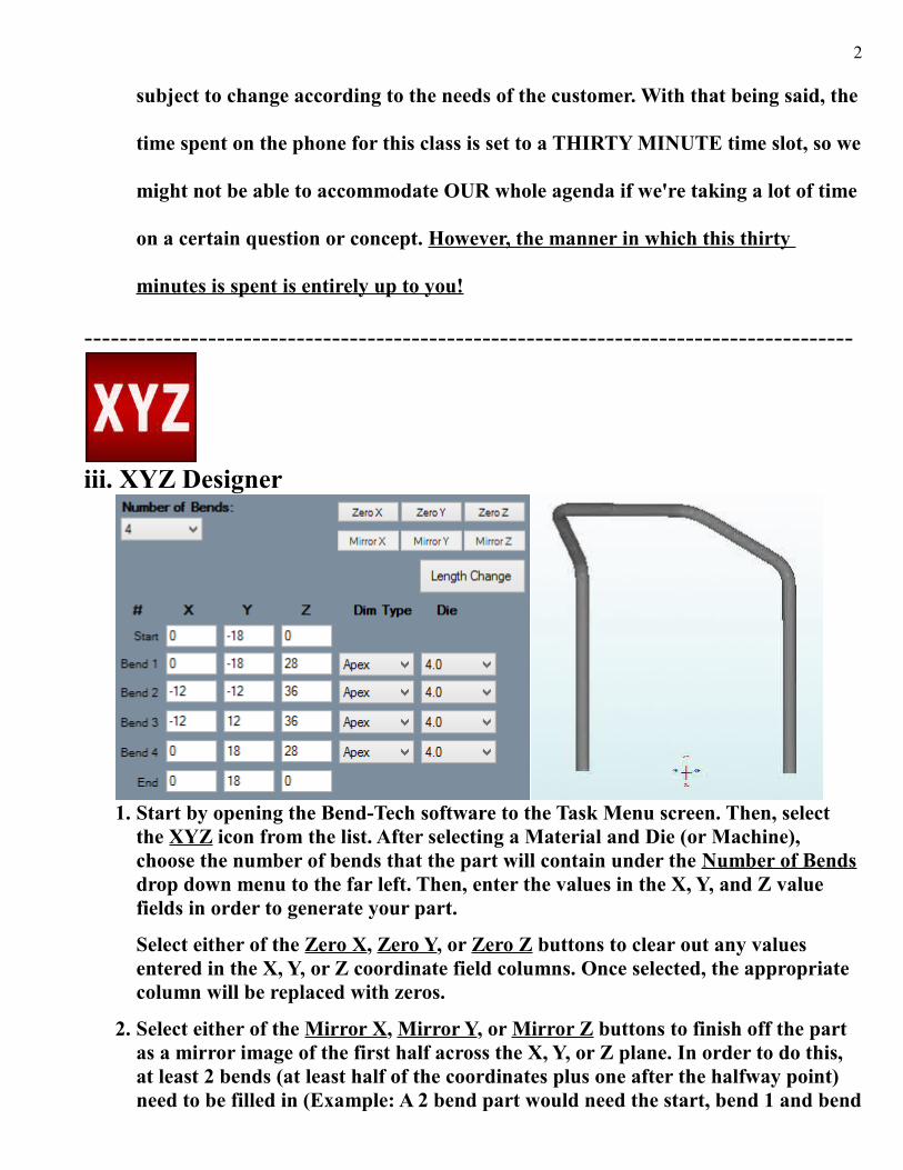
iii. XYZ Designer
1. Start by opening the Bend-Tech software to the Task Menu screen. Then, select the XYZ icon from the list. After selecting a Material and Die (or Machine), choose the number of bends that the part will contain under the Number of Bends drop down menu to the far left. Then, enter the values in the X, Y, and Z value fields in order to generate your part.
Select either of the Zero X, Zero Y, or Zero Z buttons to clear out any values entered in the X, Y, or Z coordinate field columns. Once selected, the appropriate column will be replaced with zeros.
2. Select either of the Mirror X, Mirror Y, or Mirror Z buttons to finish off the part as a mirror image of the first half across the X, Y, or Z plane. In order to do this, at least 2 bends (at least half of the coordinates plus one after the halfway point) need to be filled in (Example: A 2 bend part would need the start, bend 1 and bend
3
2 coordinates added).
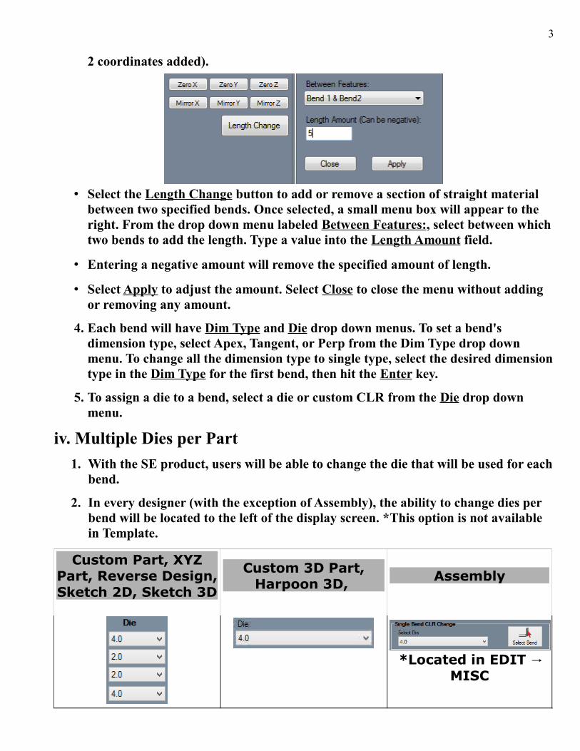
• Select the Length Change button to add or remove a section of straight material between two specified bends. Once selected, a small menu box will appear to the right. From the drop down menu labeled Between Features:, select between whichtwo bends to add the length. Type a value into the Length Amount field.
• Entering a negative amount will remove the specified amount of length.
• Select Apply to adjust the amount. Select Close to close the menu without adding or removing any amount.
4. Each bend will have Dim Type and Die drop down menus. To set a bend's dimension type, select Apex, Tangent, or Perp from the Dim Type drop down menu. To change all the dimension type to single type, select the desired dimensiontype in the Dim Type for the first bend, then hit the Enter key.
5. To assign a die to a bend, select a die or custom CLR from the Die drop down menu.
iv. Multiple Dies per Part
1. With the SE product, users will be able to change the die that will be used for eachbend.
2. In every designer (with the exception of Assembly), the ability to change dies per bend will be located to the left of the display screen. *This option is not available in Template.
Custom Part, XYZPart, Reverse Design,Sketch 2D, Sketch 3D
Custom 3D Part,Harpoon 3D,
Assembly
*Located in EDIT →MISC

4
v. Reverse Design
• The purpose the Reverse Design interface is to have a way to re-create a part by entering in lengths, rotations, and angles of the part's bends or by entering the information from a setup sheet.
1. From the Task Menu screen, select the Reverse Design icon from the list. After selecting a Material and Die (or Machine), choose the number of bends that the part will contain under the Number of Bends drop down menu to the far left.
2. To change the starting angle of the part, enter a value in the Start Angle: field.
3. To add a length, rotation, angle, or end value, just enter a number into any of the fields.
a.) Options
1. Under the TOOLS-->OPTIONS menu, you will beable to manipulate any of these settings in order toreverse engineer your part. These settings willdetermine how inputted part lengths are interpretedwhen creating a reverse design part. The definitions for each of these options are available on our 7x Wiki site.
www.bend-tech.com/wiki7/Reverse_Design

5
vi. Rotation Settings
1. The rotation settings control how rotation values are displayed in the results table.Rotation can be measured in incremental or absolute terms. Each rotation angle range can also be chosen.
2. Incremental: Select the Incremental: option and rotation angles will start from theend of the previous bend's rotation. *This option is most common for NC/CNC benders where the amount of rotation between bends is needed.
3. Absolute: Select the Absolute: option and rotation angles will always start from the very beginning of the angle scale. *This option is most common when using a plane of bend bracket or a rotary index table.
4. Rotation Scale: The rotation scale will determine what the rotation angles will range between. The rotation scale will show where the angle measurements begin and where they end. Choose a rotation scale by clicking on one of the scale options. The rotation scales available are 0 - 360, 360 - 0, (-180) - 180, and 180 - (-180).
• The 0 - 90 - 0 - 90 - 0 and 0 - 90 - 0 - 90 - 0 Reversed options will be available to you when the Absolute option is chosen. *These settings use a four-quadrant directional angle scale.
The definitions for each of these options are available on our 7x Wiki site.
www.bend-tech.com/wiki7/index.php?title=Options#Design_Settings
6
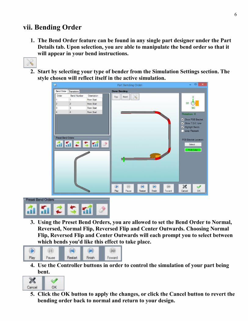
vii. Bending Order
1. The Bend Order feature can be found in any single part designer under the Part Details tab. Upon selection, you are able to manipulate the bend order so that it will appear in your bend instructions.
2. Start by selecting your type of bender from the Simulation Settings section. The style chosen will reflect itself in the active simulation.
3. Using the Preset Bend Orders, you are allowed to set the Bend Order to Normal, Reversed, Normal Flip, Reversed Flip and Center Outwards. Choosing Normal Flip, Reversed Flip and Center Outwards will each prompt you to select between which bends you'd like this effect to take place.
4. Use the Controller buttons in order to control the simulation of your part being bent.
5. Click the OK button to apply the changes, or click the Cancel button to revert the bending order back to normal and return to your design.

7
viii. Pricing
a. Pricing Setup
1. In order to set up your pricingdetails, go to TOOLS →PRICING SETTINGS.
2. The GENERAL tab is where youwill save your standard rate perhour, mark-up labor and mark-up material costs.
3. The DIE tab is where you willsave your time per bend andtime per setup between diechanges.
4. The MATERIAL tab is whereyou will save the material costper unit, time per straight cut, time per setup of a straight cut, time per notch cut,time per setup of a notched cut, time per welding node, and time to setup welding. *All units will be in inches and all time will be in minutes.
5. The PLATE tab (available forusers with our SM module) iswhere you will save the cost persquare unit (inch) of a specifiedsheet metal material.
b. Pricing Charts
1. Bend-Tech pricing charts areavailable in our Assemblyinterface under the details tab.
2. With the pricing chart windowopen you can adjust the numberof parts that will be produced tofind out the total cost. These canbe printed out from here to begiven to customers.
8
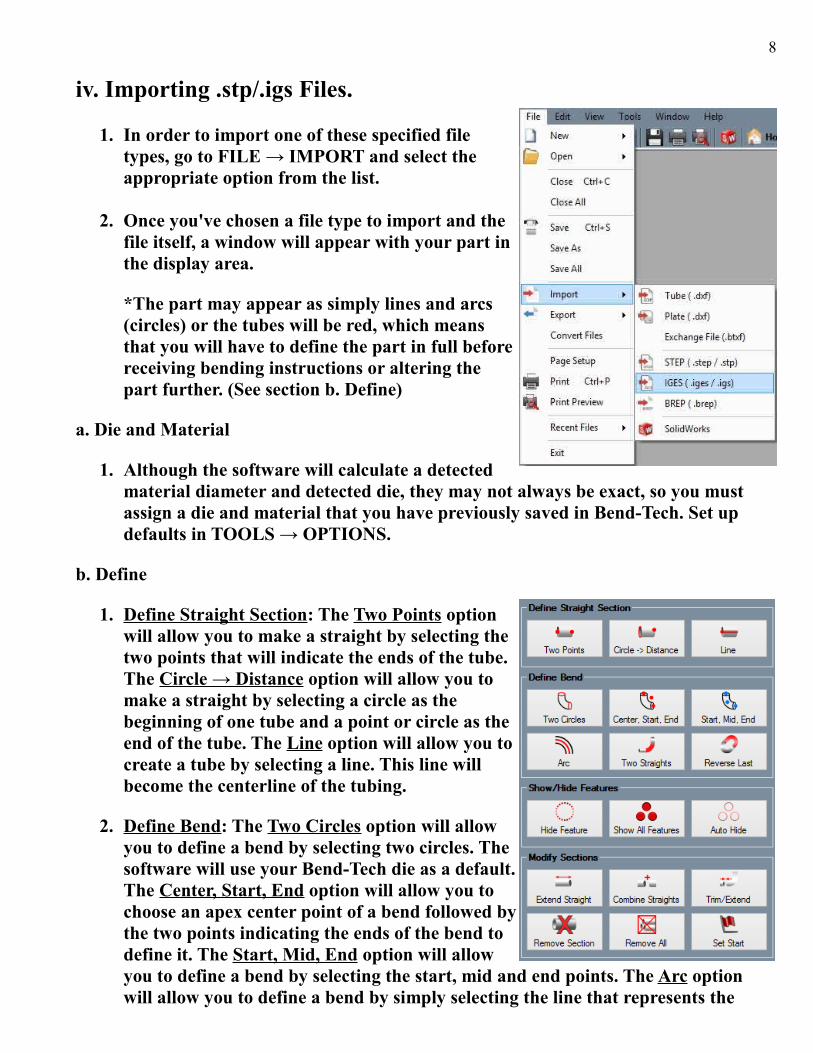
iv. Importing .stp/.igs Files.
1. In order to import one of these specified filetypes, go to FILE → IMPORT and select theappropriate option from the list.
2. Once you've chosen a file type to import and thefile itself, a window will appear with your part inthe display area.
*The part may appear as simply lines and arcs(circles) or the tubes will be red, which meansthat you will have to define the part in full beforereceiving bending instructions or altering thepart further. (See section b. Define)
a. Die and Material
1. Although the software will calculate a detectedmaterial diameter and detected die, they may not always be exact, so you must assign a die and material that you have previously saved in Bend-Tech. Set up defaults in TOOLS → OPTIONS.
b. Define
1. Define Straight Section: The Two Points optionwill allow you to make a straight by selecting thetwo points that will indicate the ends of the tube.The Circle → Distance option will allow you tomake a straight by selecting a circle as thebeginning of one tube and a point or circle as theend of the tube. The Line option will allow you tocreate a tube by selecting a line. This line willbecome the centerline of the tubing.
2. Define Bend: The Two Circles option will allowyou to define a bend by selecting two circles. Thesoftware will use your Bend-Tech die as a default.The Center, Start, End option will allow you tochoose an apex center point of a bend followed bythe two points indicating the ends of the bend todefine it. The Start, Mid, End option will allowyou to define a bend by selecting the start, mid and end points. The Arc option will allow you to define a bend by simply selecting the line that represents the

9
bend. The Two Straights option will allow you to define a bend by selecting the two straights that are meant to connect to it. The Reverse Last option allows you to reverse the last bend so that it's location will change 180 degrees.
3. Show/Hide Features: The Hide Feature option will allow you to hide the feature that you select. The Show All Features option will cause everything in the display window to re-appear. The Auto Hide option will hide all inside lines, arcs and circle features to show only the outer geometry.
4. Modify Sections: The Extend Straight option will allow you to add or remove a specified length on a straight by clicking on the part and entering the length change amount. A positive number will add that length, where a negative number will subtract that length (in inches). The Combine Straights option will allow you to fuse two straights together that are on the same plane. Simply click both tubes. The Trim/Extend option will allow you to trim a straight section back to line up with a bend or extend a straight in order to line up with a bend. Simply click the straight, then the bend to adjust the tube. The Remove Section option will allow you to remove any straight or bent section by clicking on it. The Remove All option will allow you to remove all the defined sections. The Set Start option is meant to set the starting point of the defined tubing. Click the start point and it will turn yellow to indicate the start.
c. Verify
1. Under the verify tab you will be able to select a feature in the display area and receive information like the length, start and end locations for straights, and radius, angle, start, center and end locationsfor bends.
d. Settings
1. The Import References section offers the Die References and Material Referencesoptions. The purpose of these references isto automatically assign a die and material toany bends in a part that have the samematerial and imported radius as thereference.
2. The Display options to the right include thechoices to Display TriStar, Display Features,Display Sections and Display Part. Thesewill be reflected to the left in the displayscreen.
10
3. The PickPoint Size drop down menu will give you the option to choose a PickPointsize that will reflect in the display screen.
4. The Scale option is also available for you to choose the part's Unit Type: Choices include Inches, Millimeters, Centimeters and Custom Scaling options. *All imported parts will import under the millimeters unit type by default.
• After the part is defined and up to your expectations you will have to transfer the part to Assembly to modify/add additional parts or a Single Part designer in orderto obtain the bending instructions.
x. Importing .dxf Files
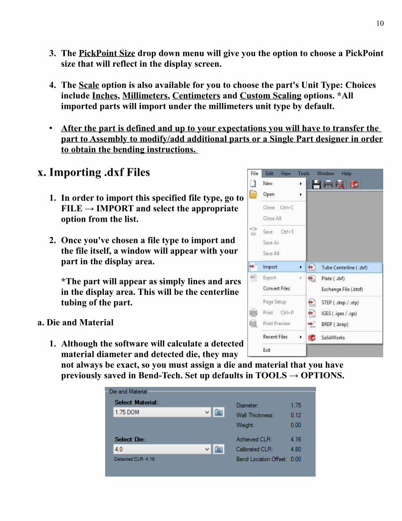
1. In order to import this specified file type, go toFILE → IMPORT and select the appropriateoption from the list.
2. Once you've chosen a file type to import andthe file itself, a window will appear with yourpart in the display area.
*The part will appear as simply lines and arcsin the display area. This will be the centerlinetubing of the part.
a. Die and Material
1. Although the software will calculate a detectedmaterial diameter and detected die, they maynot always be exact, so you must assign a die and material that you have previously saved in Bend-Tech. Set up defaults in TOOLS → OPTIONS.
11
b. Define
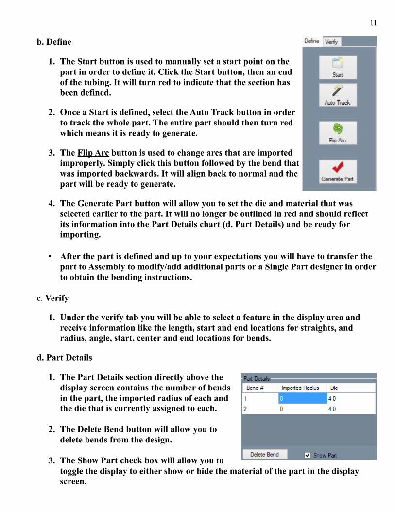
1. The Start button is used to manually set a start point on thepart in order to define it. Click the Start button, then an endof the tubing. It will turn red to indicate that the section hasbeen defined.
2. Once a Start is defined, select the Auto Track button in orderto track the whole part. The entire part should then turn redwhich means it is ready to generate.
3. The Flip Arc button is used to change arcs that are importedimproperly. Simply click this button followed by the bend thatwas imported backwards. It will align back to normal and thepart will be ready to generate.
4. The Generate Part button will allow you to set the die and material that was selected earlier to the part. It will no longer be outlined in red and should reflect its information into the Part Details chart (d. Part Details) and be ready for importing.
• After the part is defined and up to your expectations you will have to transfer the part to Assembly to modify/add additional parts or a Single Part designer in orderto obtain the bending instructions.
c. Verify
1. Under the verify tab you will be able to select a feature in the display area and receive information like the length, start and end locations for straights, and radius, angle, start, center and end locations for bends.
d. Part Details
1. The Part Details section directly above thedisplay screen contains the number of bends in the part, the imported radius of each andthe die that is currently assigned to each.
2. The Delete Bend button will allow you todelete bends from the design.
3. The Show Part check box will allow you totoggle the display to either show or hide the material of the part in the display screen.
12
xi. Nesting
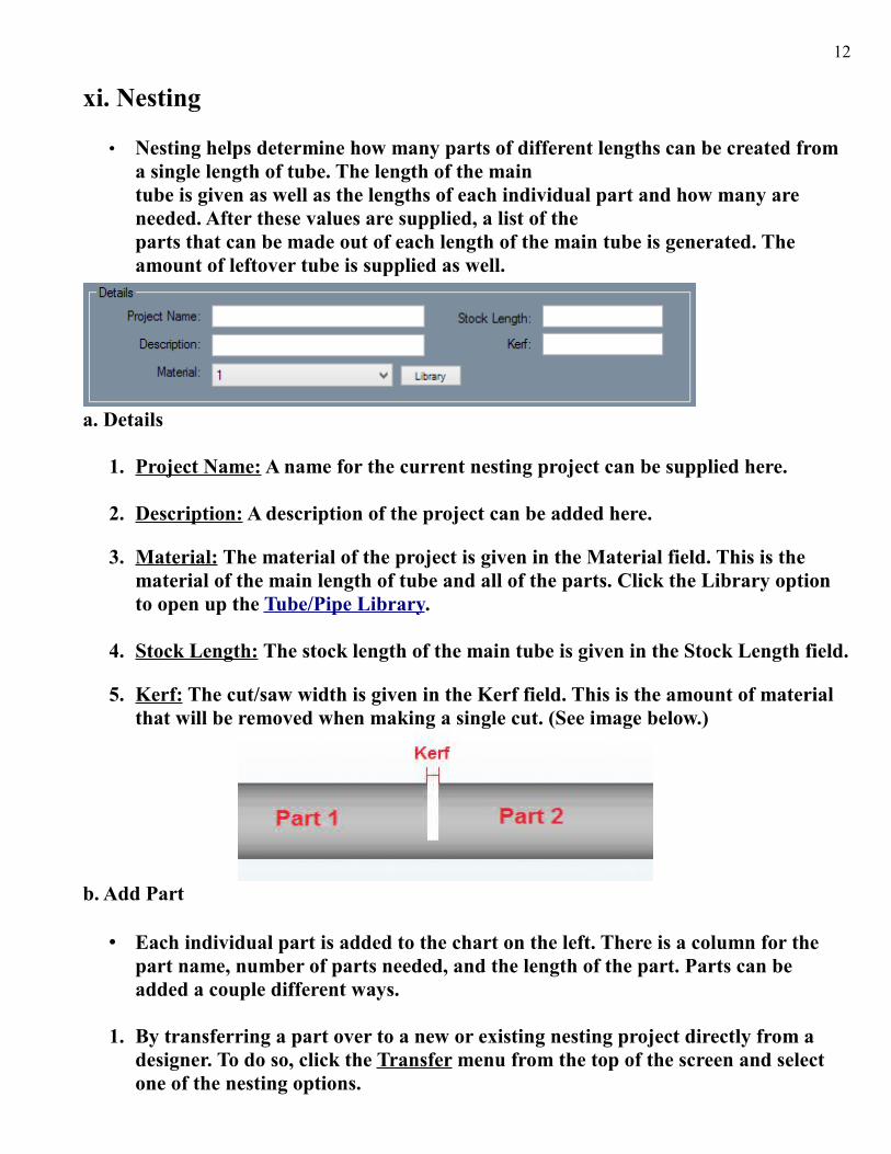
• Nesting helps determine how many parts of different lengths can be created from a single length of tube. The length of the main tube is given as well as the lengths of each individual part and how many are needed. After these values are supplied, a list of the parts that can be made out of each length of the main tube is generated. The amount of leftover tube is supplied as well.
a. Details
1. Project Name: A name for the current nesting project can be supplied here.
2. Description: A description of the project can be added here.
3. Material: The material of the project is given in the Material field. This is the material of the main length of tube and all of the parts. Click the Library option to open up the Tube/Pipe Library.
4. Stock Length: The stock length of the main tube is given in the Stock Length field.
5. Kerf: The cut/saw width is given in the Kerf field. This is the amount of material that will be removed when making a single cut. (See image below.)
b. Add Part
• Each individual part is added to the chart on the left. There is a column for the part name, number of parts needed, and the length of the part. Parts can be added a couple different ways.
1. By transferring a part over to a new or existing nesting project directly from a designer. To do so, click the Transfer menu from the top of the screen and select one of the nesting options.
13
2. By manually typing in a part name, number of parts needed, and the total length of the part. To do this, click in the Name field in next empty row. Type in the nameof the part. Click the tab key, or click in the next column to type in how many of this part is needed. Click the tab key, or click in the next column and enter the length of this part. Once these three values are supplied, a part has been successfully added to the nesting project.
c. Calculate Results
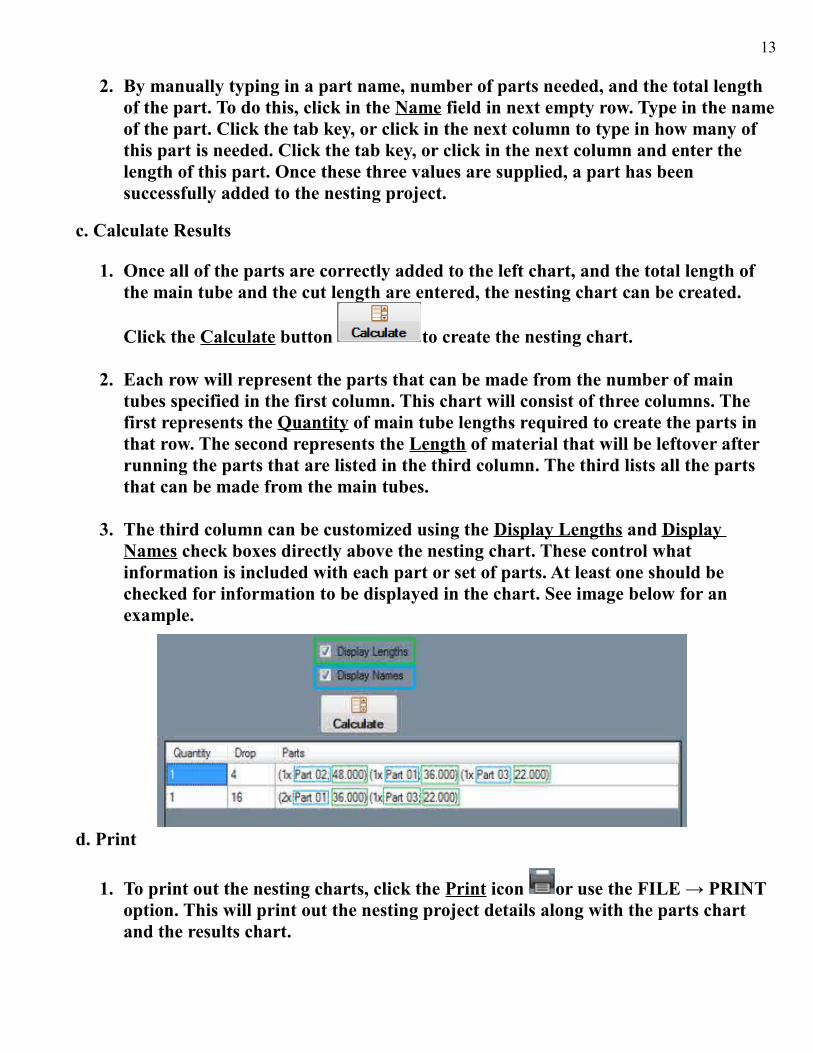
1. Once all of the parts are correctly added to the left chart, and the total length of the main tube and the cut length are entered, the nesting chart can be created.
Click the Calculate button to create the nesting chart.
2. Each row will represent the parts that can be made from the number of main tubes specified in the first column. This chart will consist of three columns. The first represents the Quantity of main tube lengths required to create the parts in that row. The second represents the Length of material that will be leftover after running the parts that are listed in the third column. The third lists all the parts that can be made from the main tubes.
3. The third column can be customized using the Display Lengths and Display Names check boxes directly above the nesting chart. These control what information is included with each part or set of parts. At least one should be checked for information to be displayed in the chart. See image below for an example.
d. Print
1. To print out the nesting charts, click the Print icon or use the FILE → PRINT option. This will print out the nesting project details along with the parts chart and the results chart.
14
Support Concerns or Questions:
Contact Our Support Team
Bend-Tech LLC.
Contact InfoPhone: 715-294-2000
Email: [email protected]: www.Bend-Tech.com
Address: 729 Prospect Ave. Osceola, WI,54020
****************************************************************************
The information transmitted is intended solely for the individual or entity to which it isaddressed and may contain confidential and/or privileged material. Any review,
retransmission, dissemination or other use of or taking action in reliance upon thisinformation by persons or entities other than the intended recipient is prohibited. Ifyou have received this email in error please contact the sender by reply e-mail and
destroy all copies of the original message.*********************************************************************
*******