Embed Size (px)
Citation preview
1
Bend-Tech Quick StartTraining Class
----------------------------------------------------------------------------------------------------------------------------
i. Things To Know• This class worksheet is designed to walk the user through setting up and
saving die, material and bender information, adjusting personal settings to
the user's specifications, and creating parts in the Template, Custom Part,
and Assembly design interfaces. As you go through this class, later
procedures will assume that you understand all earlier procedures. Because
of this, it is very important that you carefully step through this guide,
understanding everything along the way.
• A few key items need to be addressed before starting the step-by-step instructions of this tutorial. It is very important for Bend-Tech users to completely understand these items:
1) PickPoints PICKPOINTS ARE USED FOR EVERYTHING. The software is largely run in full 3D. Because a computer screen is only 2D, there is an unlimited amount of depth behind and in front of the cursor. A PickPoint is a point in 3D space that canbe used for creating, editing, and placing parts in a design. PickPoints can be placed in a 2D environment by having their depth manually entered in the appropriate value fields.
• There are 2 types of PickPoints; Those automatically created by the part by default (various colors) and user-defined points (green). In addition, the initial (0,0,0) point is an automatic point that resides at the center of the Tri-Star. The Tri-Star is our directional definition locator.
2) Center Line & Apex

2
• Center Line: In the Assembly design environment we are working exclusively with the center-line of a part, as compared to the inside or outside.
• Apex: Most bend locations are created in Assembly design with the Apex. Our definition of apex is the intersection of the straight tubes as if there wasn’t a radius.
This is demonstrated in the picture below.
3) Locational Orientation • Designing seems to work the best if users imagine they are standing behind the
vehicle at a 45 degree angle. This way left is left and right is right. Take a minute and examine the Tri-Star to get your orientation.
Notice how the truck in the picture is setup with the same orientation.
----------------------------------------------------------------------------------------------------------------------------
ii. Getting Started1) General Issues
• For some users, the setup process can be confusing. We are very aware that
many of our customers are better at fabricating in the shop or garage than
3
they are at operating computers. And that's OK!
WE'RE HERE TO HELP YOU!
• While this Class Guide has its own instructions to meet its own goals in
teaching you the basics to your Bend-Tech software, the over-the-phone
training class is subject to change according to the needs of the customer.
With that being said, the time spent on the phone for this class is set to a
THIRTY MINUTE time slot, so we might not be able to accommodate OUR
whole agenda if we're taking a lot of time on a certain question or concept.
However, the manner in which this thirty minutes is spent is entirely up to
you!
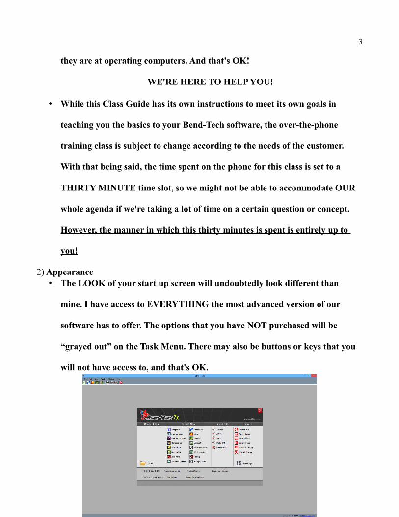
2) Appearance• The LOOK of your start up screen will undoubtedly look different than
mine. I have access to EVERYTHING the most advanced version of our
software has to offer. The options that you have NOT purchased will be
“grayed out” on the Task Menu. There may also be buttons or keys that you
will not have access to, and that's OK.
4
----------------------------------------------------------------------------------------------------------------------------
iii. Material (Tube)
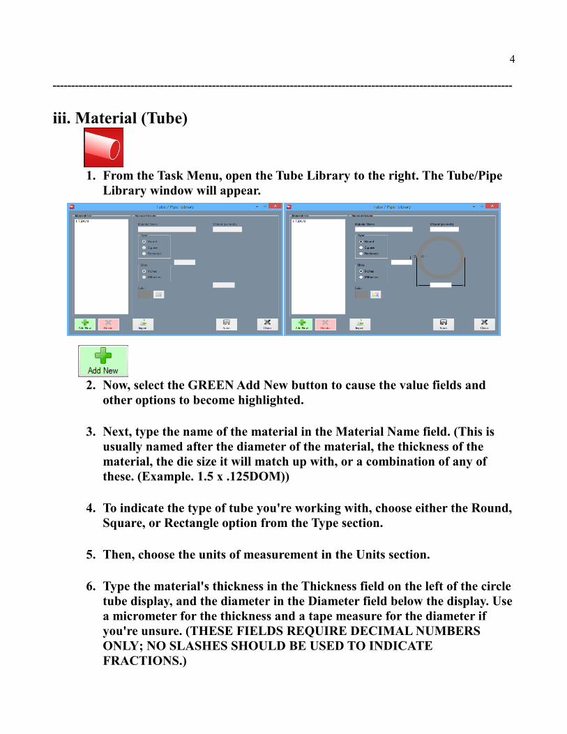
1. From the Task Menu, open the Tube Library to the right. The Tube/Pipe Library window will appear.
2. Now, select the GREEN Add New button to cause the value fields and other options to become highlighted.
3. Next, type the name of the material in the Material Name field. (This is usually named after the diameter of the material, the thickness of the material, the die size it will match up with, or a combination of any of these. (Example. 1.5 x .125DOM))
4. To indicate the type of tube you're working with, choose either the Round,Square, or Rectangle option from the Type section.
5. Then, choose the units of measurement in the Units section.
6. Type the material's thickness in the Thickness field on the left of the circle tube display, and the diameter in the Diameter field below the display. Usea micrometer for the thickness and a tape measure for the diameter if you're unsure. (THESE FIELDS REQUIRE DECIMAL NUMBERS ONLY; NO SLASHES SHOULD BE USED TO INDICATE FRACTIONS.)
5
7. Click the Save button when your material's specifications have been properly entered. The material will be saved to your Material list forever, or until you delete it.
8. You can either enter all the different materials you intend on using by repeating the steps we've just taken, or click the Close button if you're finished.
----------------------------------------------------------------------------------------------------------------------------
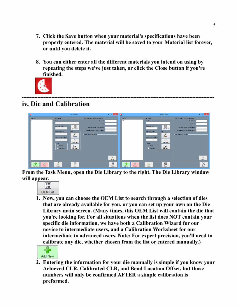
iv. Die and Calibration
From the Task Menu, open the Die Library to the right. The Die Library window will appear.
1. Now, you can choose the OEM List to search through a selection of dies that are already available for you, or you can set up your own on the Die Library main screen. (Many times, this OEM List will contain the die thatyou're looking for. For all situations when the list does NOT contain your specific die information, we have both a Calibration Wizard for our novice to intermediate users, and a Calibration Worksheet for our intermediate to advanced users. Note: For expert precision, you'll need to calibrate any die, whether chosen from the list or entered manually.)
2. Entering the information for your die manually is simple if you know yourAchieved CLR, Calibrated CLR, and Bend Location Offset, but those numbers will only be confirmed AFTER a simple calibration is preformed.
6
----------------------------------------------------------------------------------------------------------------------------
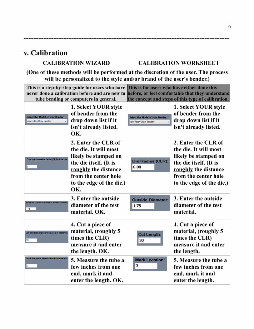
v. Calibration CALIBRATION WIZARD CALIBRATION WORKSHEET
(One of these methods will be performed at the discretion of the user. The processwill be personalized to the style and/or brand of the user's bender.)
This is a step-by-step guide for users who havenever done a calibration before and are new to
tube bending or computers in general.
This is for users who have either done this before, or feel comfortable that they understandthe concept and steps of this type of calibration.
1. Select YOUR style of bender from the drop down list if it isn't already listed. OK.
1. Select YOUR style of bender from the drop down list if it isn't already listed.
2. Enter the CLR of the die. It will most likely be stamped on the die itself. (It is roughly the distance from the center hole to the edge of the die.)OK.
2. Enter the CLR of the die. It will most likely be stamped on the die itself. (It is roughly the distance from the center hole to the edge of the die.)
3. Enter the outside diameter of the test material. OK.
3. Enter the outside diameter of the test material.
4. Cut a piece of material, (roughly 5 times the CLR) measure it and enter the length. OK.
4. Cut a piece of material, (roughly 5 times the CLR) measure it and enter the length.
5. Measure the tube a few inches from one end, mark it and enter the length. OK.
5. Measure the tube a few inches from one end, mark it and enter the length.
7
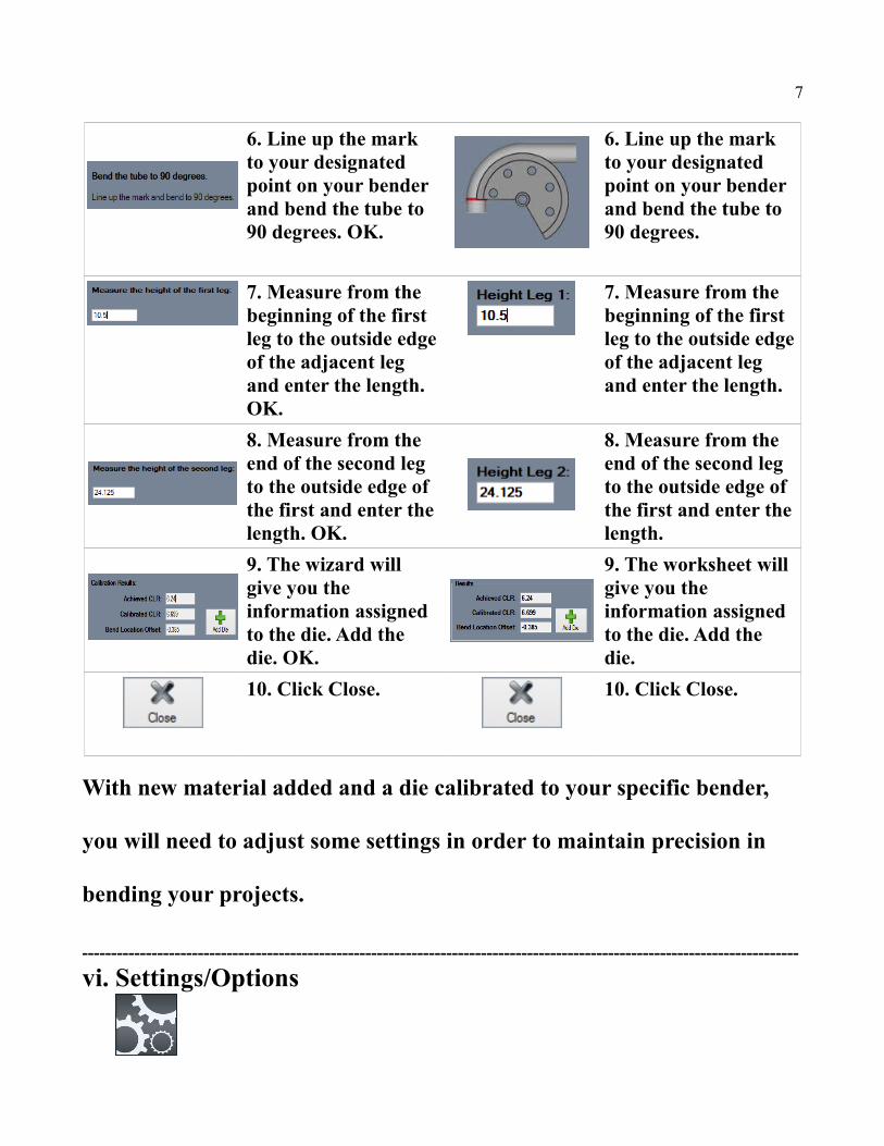
6. Line up the mark to your designated point on your bender and bend the tube to 90 degrees. OK.
6. Line up the mark to your designated point on your bender and bend the tube to 90 degrees.
7. Measure from the beginning of the first leg to the outside edgeof the adjacent leg and enter the length. OK.
7. Measure from the beginning of the first leg to the outside edgeof the adjacent leg and enter the length.
8. Measure from the end of the second leg to the outside edge of the first and enter the length. OK.
8. Measure from the end of the second leg to the outside edge of the first and enter the length.
9. The wizard will give you the information assigned to the die. Add the die. OK.
9. The worksheet will give you the information assigned to the die. Add the die.
10. Click Close. 10. Click Close.
With new material added and a die calibrated to your specific bender,
you will need to adjust some settings in order to maintain precision in
bending your projects.
----------------------------------------------------------------------------------------------------------------------------
vi. Settings/Options
8
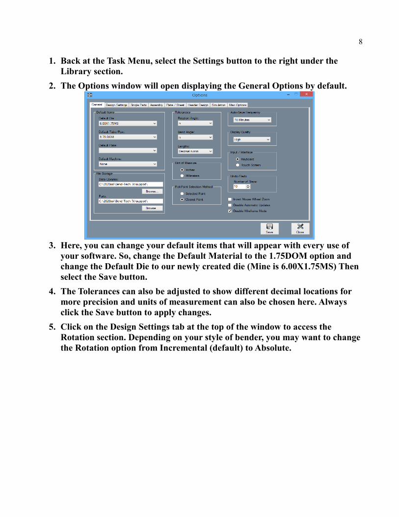
1. Back at the Task Menu, select the Settings button to the right under the Library section.
2. The Options window will open displaying the General Options by default.
3. Here, you can change your default items that will appear with every use of your software. So, change the Default Material to the 1.75DOM option and change the Default Die to our newly created die (Mine is 6.00X1.75MS) Then select the Save button.
4. The Tolerances can also be adjusted to show different decimal locations for more precision and units of measurement can also be chosen here. Always click the Save button to apply changes.
5. Click on the Design Settings tab at the top of the window to access the Rotation section. Depending on your style of bender, you may want to changethe Rotation option from Incremental (default) to Absolute.

9
6. Change the Dimension Location in the center to accommodate either a Rotary Draw, Rotary Compression, or Center Compression bender. Then, click Save to keep these settings. After saving, the adjustments will be appliedonly after RESTARTING the software.
7. Restart the software now to apply our changes.
----------------------------------------------------------------------------------------------------------------------------
vii. Template, Custom Part and Assembly Designers
1. Back in the Task Menu, start by selecting the Template designer icon. The New Part-Template window will appear with the 4 Bends option already selected by default.
2. From there, select the Double Bevel Hoop button on the top left to indicate the style of the part. The Center Line option will be selected by default.
3. A window will appear labeled Bend-Tech – [Template Part – 1]. Now,

10
maximize the screen and enter the numbers below into the corresponding fields to the left of your screen.
4. The part will appear to the right in the Display Area.
5. Now, we will transfer the part out into our Assembly Designer so that we can assemble it together with other parts. So, go up to the Transfer button at the top of the screen, select it and choose the New Assembly option. The Prepare for Assembly window will appear.
11
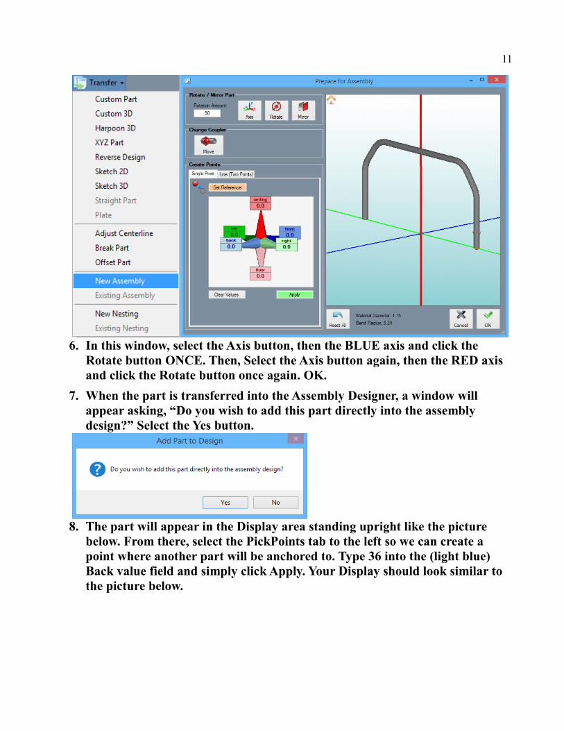
6. In this window, select the Axis button, then the BLUE axis and click the Rotate button ONCE. Then, Select the Axis button again, then the RED axis and click the Rotate button once again. OK.
7. When the part is transferred into the Assembly Designer, a window will appear asking, “Do you wish to add this part directly into the assembly design?” Select the Yes button.
8. The part will appear in the Display area standing upright like the picture below. From there, select the PickPoints tab to the left so we can create a point where another part will be anchored to. Type 36 into the (light blue) Back value field and simply click Apply. Your Display should look similar to the picture below.
12
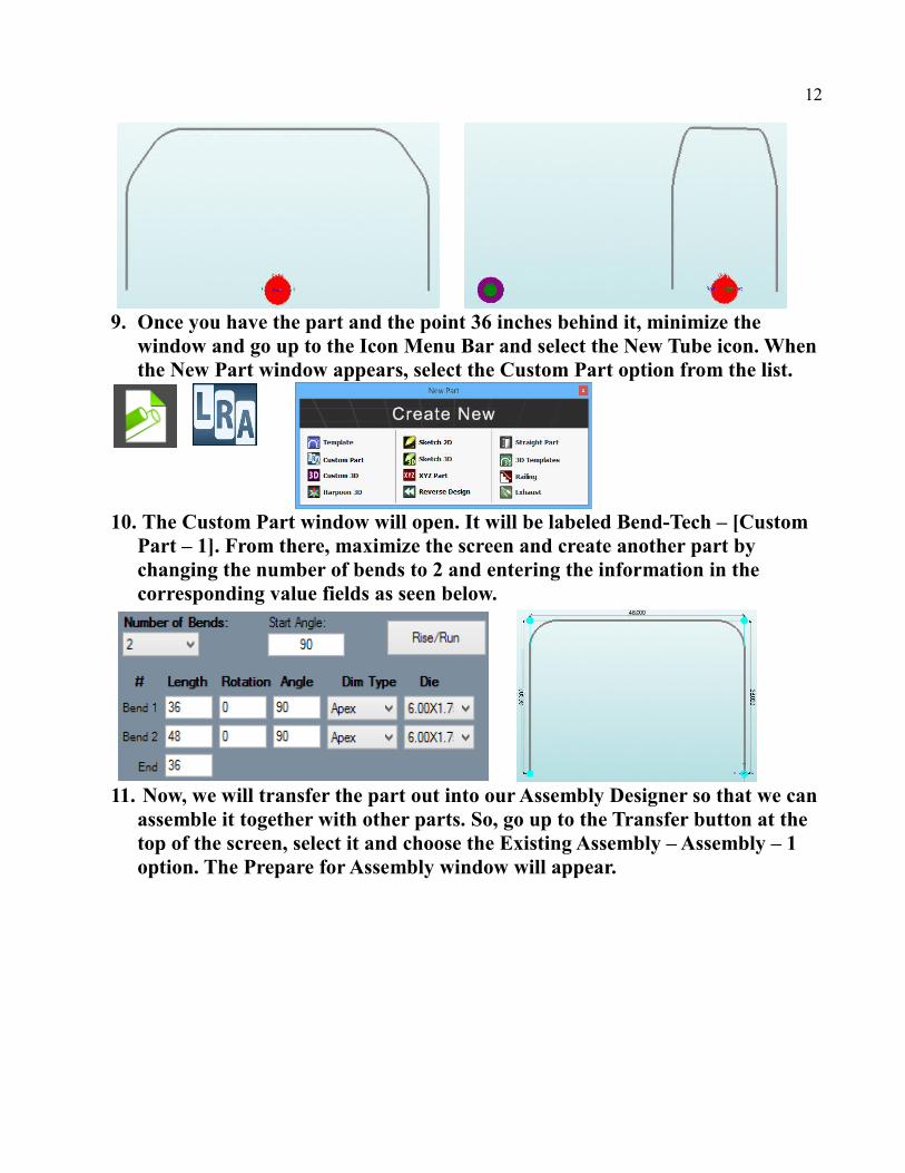
9. Once you have the part and the point 36 inches behind it, minimize the window and go up to the Icon Menu Bar and select the New Tube icon. Whenthe New Part window appears, select the Custom Part option from the list.
10. The Custom Part window will open. It will be labeled Bend-Tech – [Custom Part – 1]. From there, maximize the screen and create another part by changing the number of bends to 2 and entering the information in the corresponding value fields as seen below.
11. Now, we will transfer the part out into our Assembly Designer so that we canassemble it together with other parts. So, go up to the Transfer button at the top of the screen, select it and choose the Existing Assembly – Assembly – 1 option. The Prepare for Assembly window will appear.
13
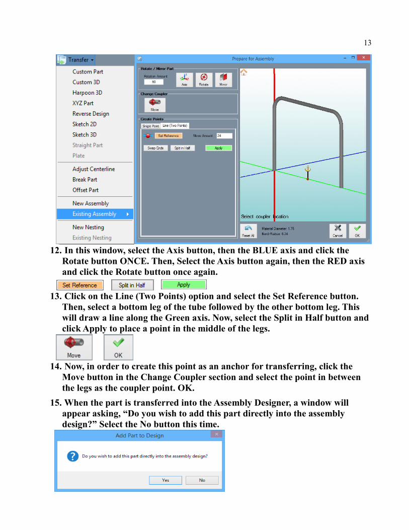
12. In this window, select the Axis button, then the BLUE axis and click the Rotate button ONCE. Then, Select the Axis button again, then the RED axis and click the Rotate button once again.
13. Click on the Line (Two Points) option and select the Set Reference button. Then, select a bottom leg of the tube followed by the other bottom leg. This will draw a line along the Green axis. Now, select the Split in Half button and click Apply to place a point in the middle of the legs.
14. Now, in order to create this point as an anchor for transferring, click the Move button in the Change Coupler section and select the point in between the legs as the coupler point. OK.
15. When the part is transferred into the Assembly Designer, a window will appear asking, “Do you wish to add this part directly into the assembly design?” Select the No button this time.
14
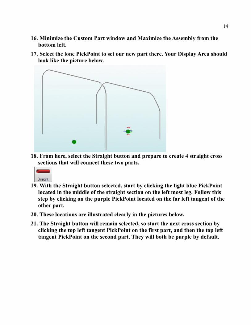
16. Minimize the Custom Part window and Maximize the Assembly from the bottom left.
17. Select the lone PickPoint to set our new part there. Your Display Area shouldlook like the picture below.
18. From here, select the Straight button and prepare to create 4 straight cross sections that will connect these two parts.
19. With the Straight button selected, start by clicking the light blue PickPoint located in the middle of the straight section on the left most leg. Follow this step by clicking on the purple PickPoint located on the far left tangent of the other part.
20. These locations are illustrated clearly in the pictures below.
21. The Straight button will remain selected, so start the next cross section by clicking the top left tangent PickPoint on the first part, and then the top left tangent PickPoint on the second part. They will both be purple by default.
15
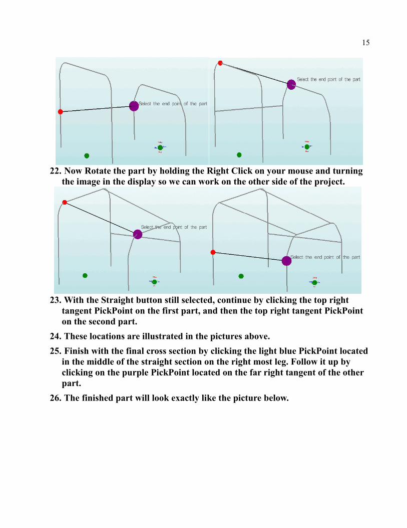
22. Now Rotate the part by holding the Right Click on your mouse and turning the image in the display so we can work on the other side of the project.
23. With the Straight button still selected, continue by clicking the top right tangent PickPoint on the first part, and then the top right tangent PickPoint on the second part.
24. These locations are illustrated in the pictures above.
25. Finish with the final cross section by clicking the light blue PickPoint locatedin the middle of the straight section on the right most leg. Follow it up by clicking on the purple PickPoint located on the far right tangent of the other part.
26. The finished part will look exactly like the picture below.

16
27. Next we will see how to make fishmouth cuts/notches for the intersections of tubes we've just made.
----------------------------------------------------------------------------------------------------------------------------
viii. Cutting
• Cutting may be performed using a variety of tools, (holesaw, plasma cutter,
torch, grinder, etc.). Bend-Tech PRO and SE products give the user
information on angles for cuts, and cutting wrappers which are meant to be
printed out and wrapped around the tube for cutting precision. Assuming the
user has all the proper equipment, the Bend-Tech software can accommodate
you with everything else.
1. Start by selecting the Cutting tab within the Assembly Designer. Then, click the Auto-Cut button.
17
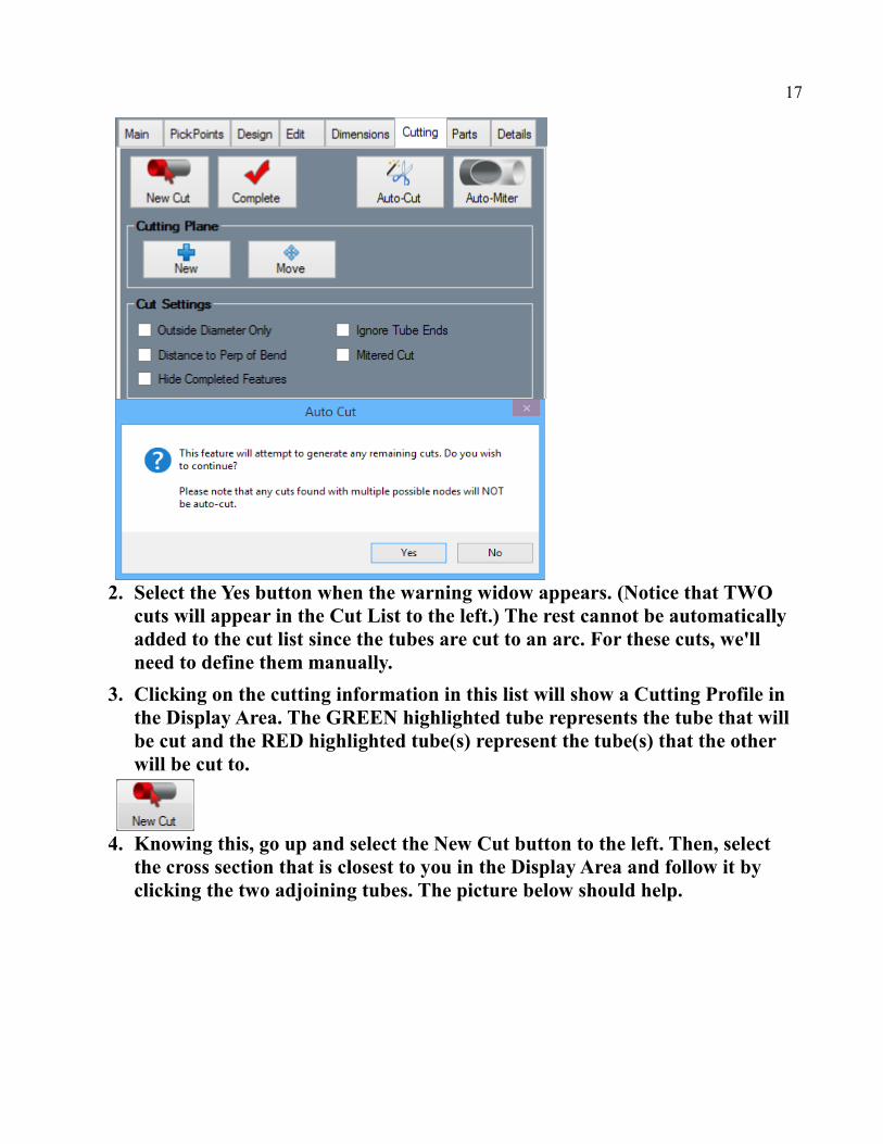
2. Select the Yes button when the warning widow appears. (Notice that TWO cuts will appear in the Cut List to the left.) The rest cannot be automatically added to the cut list since the tubes are cut to an arc. For these cuts, we'll need to define them manually.
3. Clicking on the cutting information in this list will show a Cutting Profile in the Display Area. The GREEN highlighted tube represents the tube that will be cut and the RED highlighted tube(s) represent the tube(s) that the other will be cut to.
4. Knowing this, go up and select the New Cut button to the left. Then, select the cross section that is closest to you in the Display Area and follow it by clicking the two adjoining tubes. The picture below should help.
18
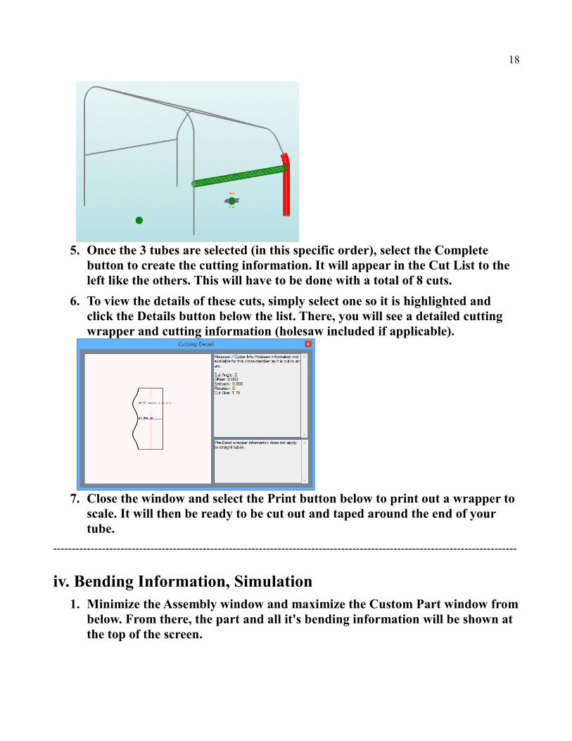
5. Once the 3 tubes are selected (in this specific order), select the Complete button to create the cutting information. It will appear in the Cut List to the left like the others. This will have to be done with a total of 8 cuts.
6. To view the details of these cuts, simply select one so it is highlighted and click the Details button below the list. There, you will see a detailed cutting wrapper and cutting information (holesaw included if applicable).
7. Close the window and select the Print button below to print out a wrapper to scale. It will then be ready to be cut out and taped around the end of your tube.
----------------------------------------------------------------------------------------------------------------------------
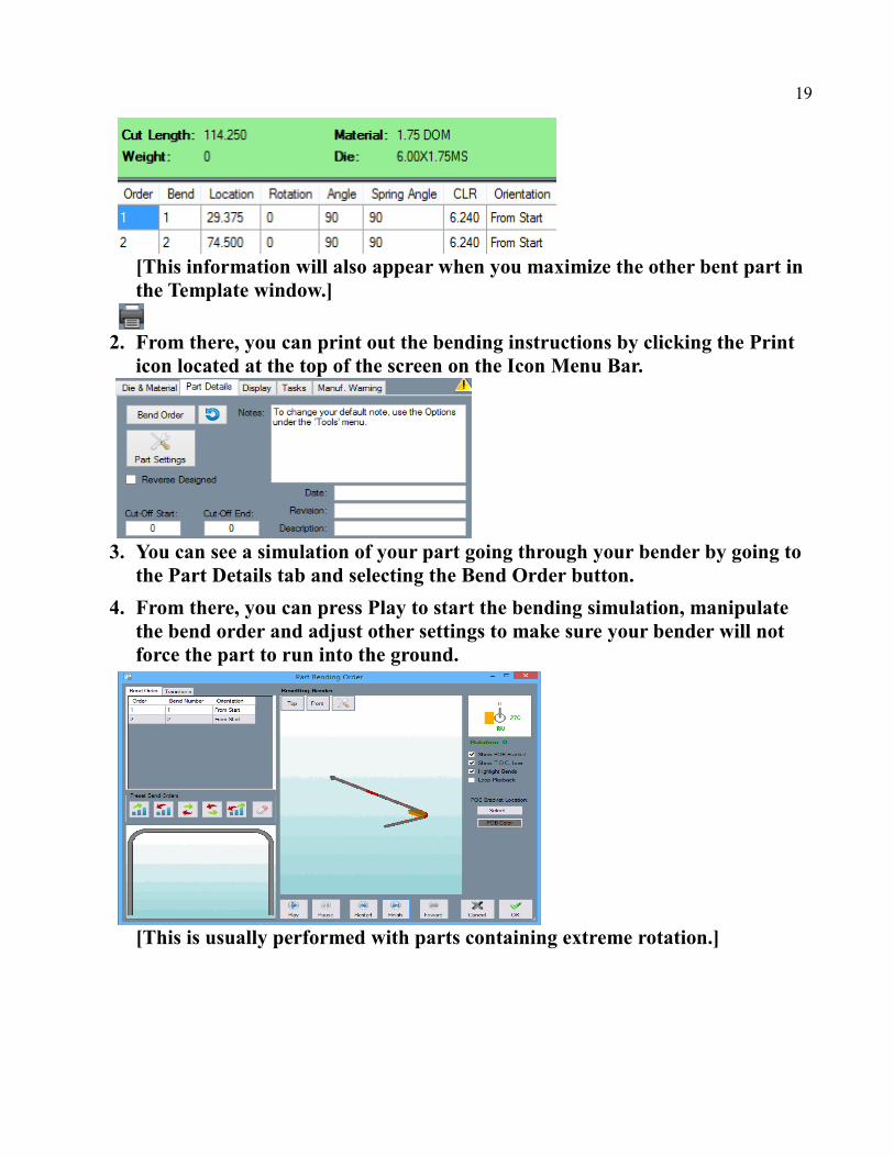
iv. Bending Information, Simulation1. Minimize the Assembly window and maximize the Custom Part window from
below. From there, the part and all it's bending information will be shown at the top of the screen.
19
[This information will also appear when you maximize the other bent part in the Template window.]
2. From there, you can print out the bending instructions by clicking the Print icon located at the top of the screen on the Icon Menu Bar.
3. You can see a simulation of your part going through your bender by going to the Part Details tab and selecting the Bend Order button.
4. From there, you can press Play to start the bending simulation, manipulate the bend order and adjust other settings to make sure your bender will not force the part to run into the ground.
[This is usually performed with parts containing extreme rotation.]

20
Support Concerns or Questions:
Michael
Support Team
2020 Software Solutions, Inc.
Contact InfoPhone: 651-257-8715Email: [email protected]: www.Bend-Tech.comAddress: 33510 Lincoln Rd, Lindstrom, MN 55045
****************************************************************************The information transmitted is intended solely for the individual or entity to which it is addressed and may contain confidential and/or privileged material. Any review, retransmission, dissemination or otheruse of or taking action in reliance upon this information by persons or entities other than the intended recipient is prohibited. If you have received this email in error please contact the sender by reply e-mailand destroy all copies of the original message.****************************************************************************