Embed Size (px)
Citation preview
Word doc. QSG-RY11841-ECU-DC v2 © H1 7/8/13 1
Quick Start Guide – RIVA/Athena Yamaha ECU
PART# - RY11841-ECU-DC
APPLICATION(S): Yamaha 1.8L Engine Models (SHO/HO)
RIVA/Athena ECU Manager Web Site: www.riva-athena.com
NOTE: YOU MUST PERFORM PHYSICAL INSTALLATION BEFORE PROCEEDING.
PLEASE REFER TO INSTALLATION INSTRUCTIONS SUPPLIED WITH YOUR ECU.
Table of Contents by Section
1. Required Performance Parts
2. Installation of Maya (PC Software)
3. Downloading & Saving Base Maps
4. Loading a Device File / Opening a Base Map
5. Setting Com Port
6. Programming ECU
7. Diagnostics & Fault Codes
8. Setting Throttle Position Sensor (TPS)
9. Overview of Maya User Interface
10. Glossary

Word doc. QSG-RY11841-ECU-DC v2 © H1 7/8/13 2
Section 1 – Required Performance Parts
RIVA/Athena ECU Maps are designed to function with specific RIVA parts kits. Please visit www.rivaracing.com/kits for more information.
RIVA Power Filter Kit: Stage 2, 3, & 4
Supercharger Upgrade
◦ RIVA B1 Impeller: Stage 3
◦ RIVA E1 Impeller: Stage 4
RIVA Intercooler Upgrade
◦ RIVA OEM Intercooler Upgrade Kit: Stage 2
◦ RIVA Pro-Series Power Cooler Kit: Stage 3 & Above
RIVA Intake Manifold Upgrade Kit: Stage 2, 3, & Above
RIVA Fuel Pressure Regulator: Stage 2, 3, & Above
RIVA 100lb Pro-Series Fuel Injectors: Stage 3 & Above
RIVA 3-Bar MAP Sensor: Stage 3+ & Above
RIVA Engine Cooling Upgrade
◦ OEM Intercooler: Stage 2
◦ RIVA Power Cooler: Stage 3 & Above
‘R’ Series Pump Impeller: Stage 2, 3, & 3+
Along with the above components we recommend many others that will complement the RIVA/Athena ECU providing improved performance in acceleration, handling and top speed. Please visit www.rivaracing.com/kits for more information.
Proceed to next section.
Word doc. QSG-RY11841-ECU-DC v2 © H1 7/8/13 3
Section 2 – Installation of Maya (PC Software)
SYSTEM REQUIREMENTS:
PC Intel x86 or AMD64 compatible
Intel Pentium III or superior processor
512 Mb RAM
1 Ethernet card 10/100 Mbps
One RS232 9-pin UART16550 compatible port or one USB 1.1 or 2.0 port for ECU connection. NOTE: Not compatible with USB 3.0
One USB 1.1 or 2.0 available port (for Advanced license hardware key)
DOWNLOAD MAYA (PC SOFTWARE):
1. Go to the RIVA ECU Manager web site at www.rivaecu.com.
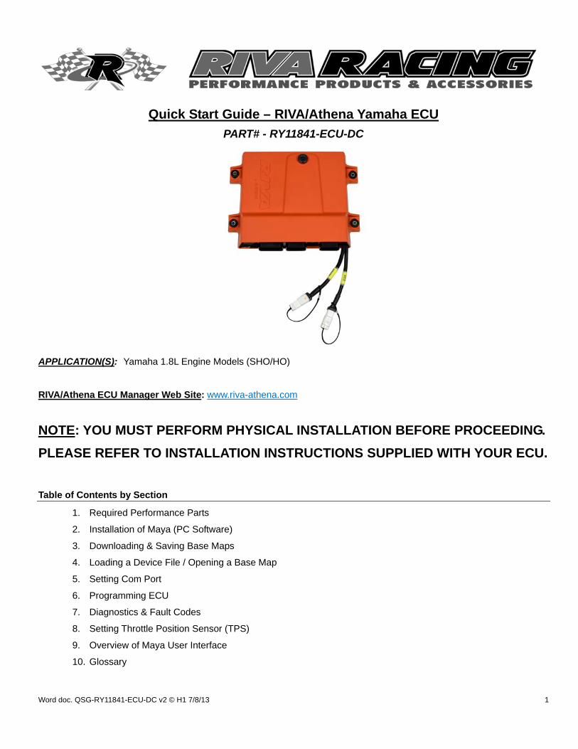
2. Select ‘Athena’.
3. Select ‘Yamaha’ model.
4. Select ‘Direct Connect’ model.
Proceed to next page.
Word doc. QSG-RY11841-ECU-DC v2 © H1 7/8/13 4
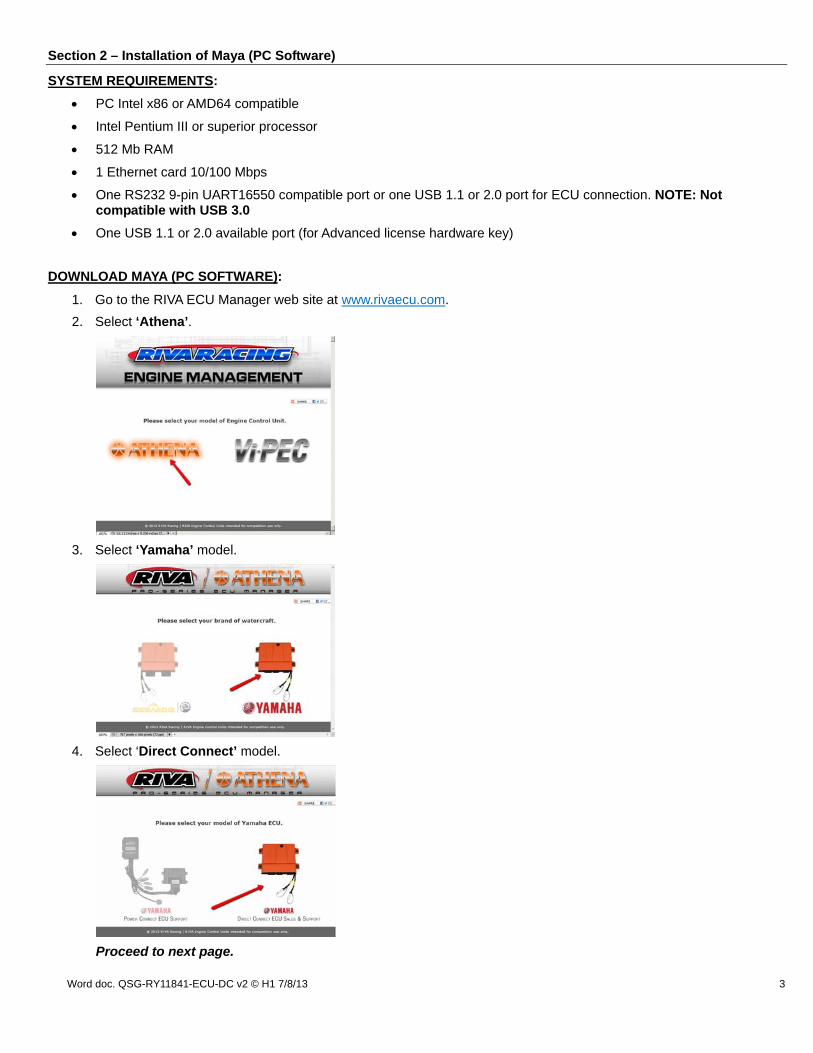
5. In the left navigation click ‘Downloads’.
6. On the Downloads page under ‘ECU’ click the icon to download Maya (PC Software).
NOTE: Maya is distributed as a single, self-installing executable, normally called ‘Maya_Install_<Version>.exe’.
Proceed to next section.
Word doc. QSG-RY11841-ECU-DC v2 © H1 7/8/13 5
INSTALL MAYA (PC SOFTWARE):
1. On your PC navigate to the downloaded file.
Windows 7 & 8: Downloads
Windows XP & Vista: Desktop
2. Open the zipped folder (or extract files) to access the installation file (Maya_Install_<Version>.exe).
3. Double-click the installation file. If you are presented with a warning window click ‘Ok’ or ‘Run’ to continue.
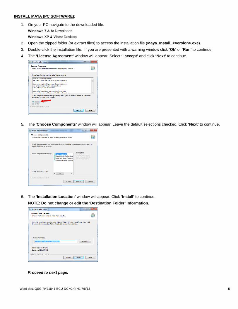
4. The ‘License Agreement’ window will appear. Select ‘I accept’ and click ‘Next’ to continue.
5. The ‘Choose Components’ window will appear. Leave the default selections checked. Click ‘Next’ to continue.
6. The ‘Installation Location’ window will appear. Click ‘Install’ to continue.
NOTE: Do not change or edit the ‘Destination Folder’ information.
Proceed to next page.
Word doc. QSG-RY11841-ECU-DC v2 © H1 7/8/13 6
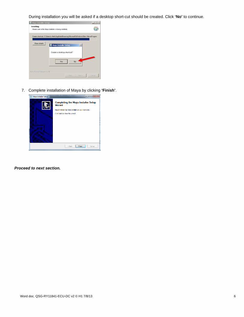
During installation you will be asked if a desktop short-cut should be created. Click ‘No’ to continue.
7. Complete installation of Maya by clicking ‘Finish’.
Proceed to next section.

Word doc. QSG-RY11841-ECU-DC v2 © H1 7/8/13 7
Section 3 – Downloading & Saving Base Maps (Configuration Files)
DOWNLOADING BASE MAPS:
1. Go to the RIVA ECU Manager web site at www.rivaecu.com.
2. Select ‘Athena’.
3. Select ‘Yamaha’.
4. Select ‘Direct Connect’ model.
5. In the left navigation click ‘Base Maps’.
Proceed to next page.

Word doc. QSG-RY11841-ECU-DC v2 © H1 7/8/13 8
6. Select the Base Map that best matches your modifications and click the stage number to go to the download page.
7. To download click the icon.
8. On your PC navigate to the downloaded file.
Windows 7 & 8: Downloads Windows XP & Vista: Desktop
Proceed to next page.
Word doc. QSG-RY11841-ECU-DC v2 © H1 7/8/13 9
9. Open the zipped folder (or extract files) to access the bundled files.
NOTE: Each download contains two (2) files. The selected Base Map (green icon) and the most current Device File (red icon). Always save both files to your PC to ensure you have the most current version of the Device File and corresponding Base Maps.
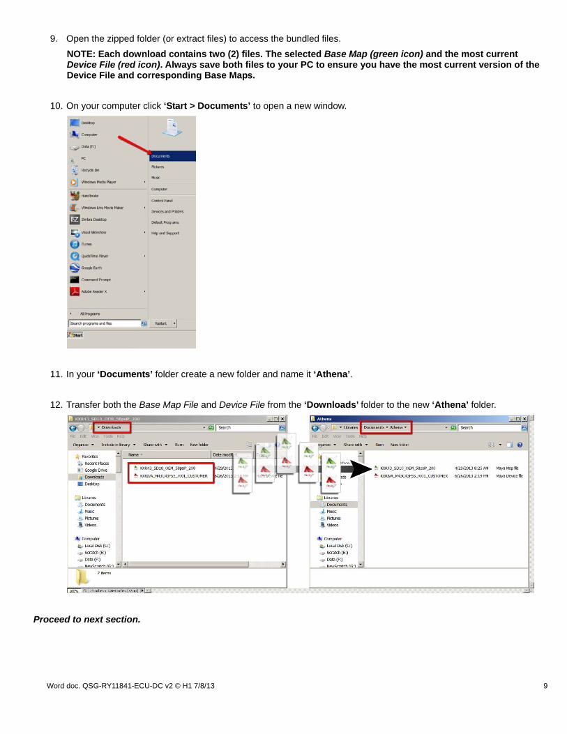
10. On your computer click ‘Start > Documents’ to open a new window.
11. In your ‘Documents’ folder create a new folder and name it ‘Athena’.
12. Transfer both the Base Map File and Device File from the ‘Downloads’ folder to the new ‘Athena’ folder.
Proceed to next section.
Word doc. QSG-RY11841-ECU-DC v2 © H1 7/8/13 10
Section 4 – Loading a Device File / Opening a Base Map
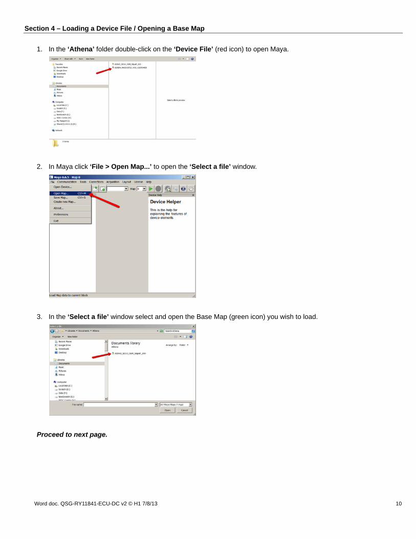
1. In the ‘Athena’ folder double-click on the ‘Device File’ (red icon) to open Maya.
2. In Maya click ‘File > Open Map...’ to open the ‘Select a file’ window.
3. In the ‘Select a file’ window select and open the Base Map (green icon) you wish to load.
Proceed to next page.
Word doc. QSG-RY11841-ECU-DC v2 © H1 7/8/13 11
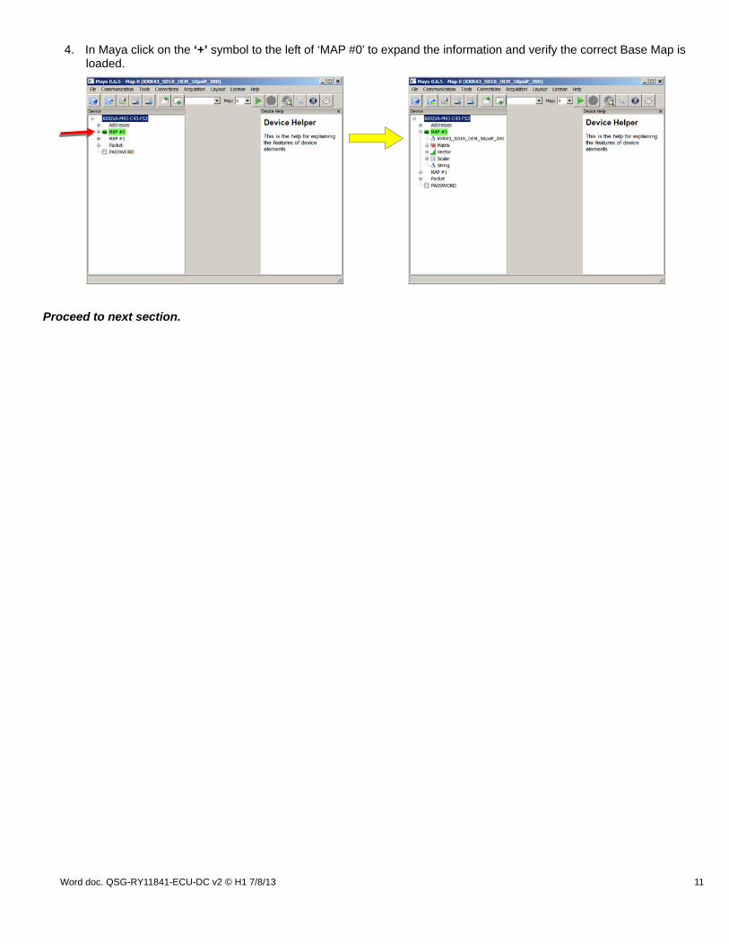
4. In Maya click on the ‘+’ symbol to the left of ‘MAP #0’ to expand the information and verify the correct Base Map is loaded.
Proceed to next section.
Word doc. QSG-RY11841-ECU-DC v2 © H1 7/8/13 12
Section 5 – Setting COM Port
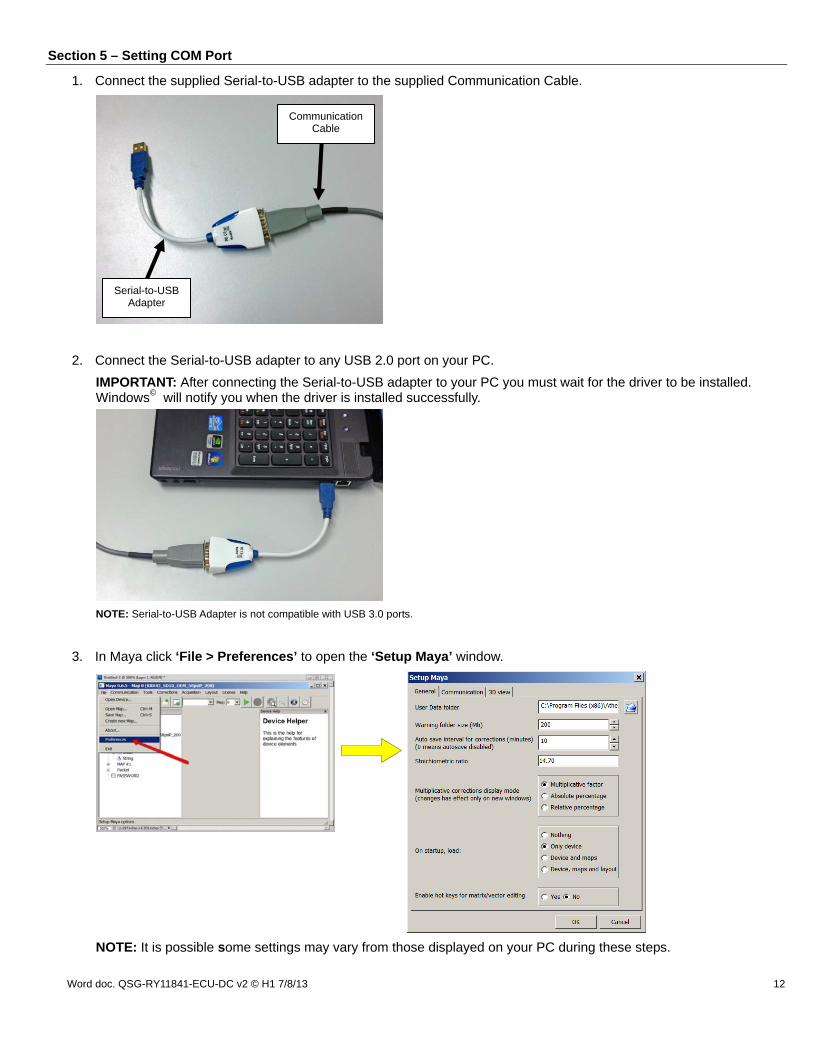
1. Connect the supplied Serial-to-USB adapter to the supplied Communication Cable.
2. Connect the Serial-to-USB adapter to any USB 2.0 port on your PC.
IMPORTANT: After connecting the Serial-to-USB adapter to your PC you must wait for the driver to be installed. Windows© will notify you when the driver is installed successfully.
NOTE: Serial-to-USB Adapter is not compatible with USB 3.0 ports.
3. In Maya click ‘File > Preferences’ to open the ‘Setup Maya’ window.
NOTE: It is possible some settings may vary from those displayed on your PC during these steps.
Serial-to-USB Adapter
Communication Cable

Word doc. QSG-RY11841-ECU-DC v2 © H1 7/8/13 13
4. In the ‘Setup Maya’ window select the ‘Communication’ tab to display the communication port preferences.
5. Click the drop down arrow for ‘Serial COM port’ to display the available COM ports. Typically there will be only one COM port to select (Below Example – ‘COM 3’). Select that option and click ‘Next’ to continue.
NOTE: COM1 is the default. Select the option displayed in the drop down menu to set your COM port.
If there are several COM port options please contact RIVA Technical Support at (954) 247-0705 or [email protected] for assistance.
Proceed to next section.

Word doc. QSG-RY11841-ECU-DC v2 © H1 7/8/13 14
Section 6 – Programming ECU
1. Install lanyard on Start/Stop switch.
2. Set Communication Cable to ‘Program Mode’.
3. Connect Communication Cable to ECU lead labeled ‘MAIN’.
4. In Maya click ‘Communication > Download to ECU’.
The ‘Programming procedure’ window will open. Wait 10 seconds and click ‘OK’ to continue.
NOTE: ECU will ‘Time Out’ after 30 seconds of inactivity. Press ‘STOP’ button, wait 10 seconds and repeat from Step 2 above.
Proceed to next page.
Program Mode: With wires CONNECTED.
Communications with the ECU are PROGRAM ONLY. Meaning the MAP file can be sent to the ECU. Live data cannot be monitored in this mode. In this mode the ECU will not allow the engine to start. Lanyard must be connected to use this mode.
NOTE: Never leave in Program Mode for extended periods of time. This will drain the battery.
Word doc. QSG-RY11841-ECU-DC v2 © H1 7/8/13 15
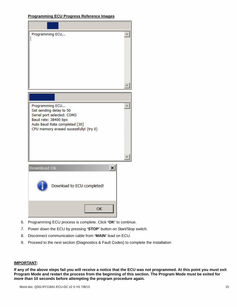
Programming ECU Progress Reference Images
6. Programming ECU process is complete. Click ‘OK’ to continue.
7. Power down the ECU by pressing ‘STOP’ button on Start/Stop switch.
8. Disconnect communication cable from ‘MAIN’ lead on ECU.
9. Proceed to the next section (Diagnostics & Fault Codes) to complete the installation
IMPORTANT:
If any of the above steps fail you will receive a notice that the ECU was not programmed. At this point you must exit Program Mode and restart the process from the beginning of this section. The Program Mode must be exited for more than 10 seconds before attempting the program procedure again.
Word doc. QSG-RY11841-ECU-DC v2 © H1 7/8/13 16
Section 7 – Diagnostics & Fault Codes
IMPORTANT:
During the installation process it is normal for fault codes to be displayed. Follow below process to clear. If faults still exist after clearing you may have a bad sensor or actuator component that requires replacing before continuing.
To display the diagnostics tool proceed as follows:
1. Install lanyard on Start/Stop switch.
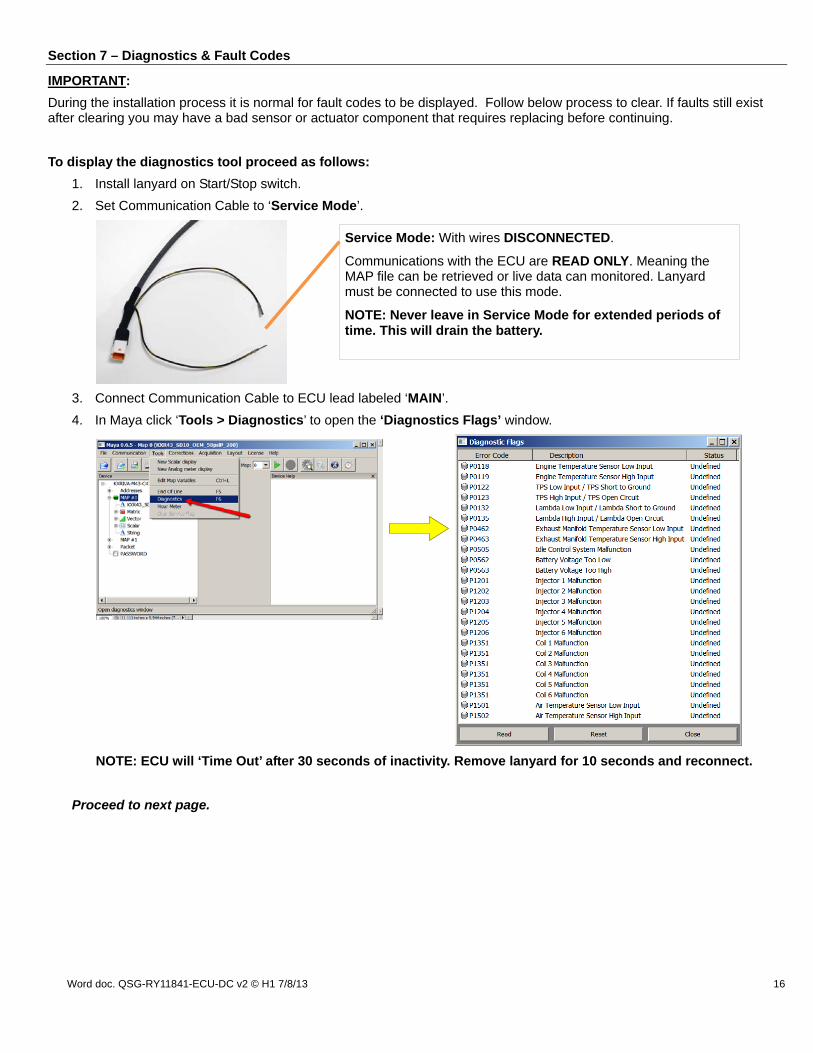
2. Set Communication Cable to ‘Service Mode’.
3. Connect Communication Cable to ECU lead labeled ‘MAIN’.
4. In Maya click ‘Tools > Diagnostics’ to open the ‘Diagnostics Flags’ window.
NOTE: ECU will ‘Time Out’ after 30 seconds of inactivity. Remove lanyard for 10 seconds and reconnect.
Proceed to next page.
Service Mode: With wires DISCONNECTED.
Communications with the ECU are READ ONLY. Meaning the MAP file can be retrieved or live data can monitored. Lanyard must be connected to use this mode.
NOTE: Never leave in Service Mode for extended periods of time. This will drain the battery.
Word doc. QSG-RY11841-ECU-DC v2 © H1 7/8/13 17
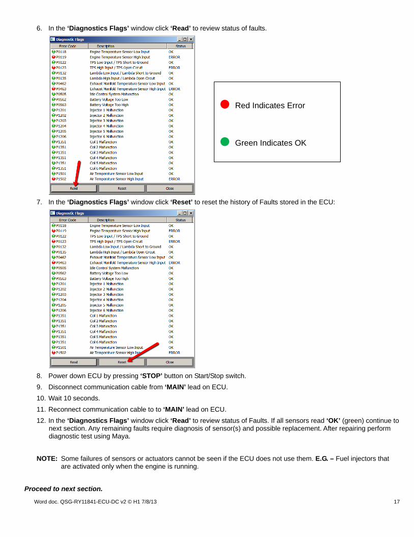
6. In the ‘Diagnostics Flags’ window click ‘Read’ to review status of faults.
7. In the ‘Diagnostics Flags’ window click ‘Reset’ to reset the history of Faults stored in the ECU:
8. Power down ECU by pressing ‘STOP’ button on Start/Stop switch.
9. Disconnect communication cable from ‘MAIN’ lead on ECU.
10. Wait 10 seconds.
11. Reconnect communication cable to to ‘MAIN’ lead on ECU.
12. In the ‘Diagnostics Flags’ window click ‘Read’ to review status of Faults. If all sensors read ‘OK’ (green) continue to next section. Any remaining faults require diagnosis of sensor(s) and possible replacement. After repairing perform diagnostic test using Maya.
NOTE: Some failures of sensors or actuators cannot be seen if the ECU does not use them. E.G. – Fuel injectors that are activated only when the engine is running.
Proceed to next section.
• Red Indicates Error
• Green Indicates OK

Word doc. QSG-RY11841-ECU-DC v2 © H1 7/8/13 18
Section 8 – Setting Throttle Position Sensor (TPS)
WARNING: The throttle calibration is automatic and requires the engine be off and hands clear of the throttle body. This process requires the ECU be powered off and on multiple times. This will be performed during the steps that follow.
1. Install lanyard on Start/Stop switch.
2. Set Communication Cable to ‘Service Mode’.
3. Connect Communication Cable to ECU lead labeled ‘MAIN’.
4. Power up the ECU by connecting the lanyard.
5. In Maya click ‘Tools > End Of Line’ to display ‘End of line parameters’ window.
NOTE: ECU will ‘Time Out’ after 30 seconds of inactivity. Remove lanyard for 10 seconds and reconnect.
Proceed to next page.
Service Mode: With wires DISCONNECTED.
Communications with the ECU are READ ONLY. Meaning the MAP file can be retrieved or live data can monitored. Lanyard must be connected to use this mode.
NOTE: Never leave in Service Mode for extended periods of time. This will drain the battery.
Word doc. QSG-RY11841-ECU-DC v2 © H1 7/8/13 19
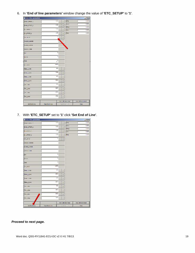
6. In ‘End of line parameters’ window change the value of 'ETC_SETUP' to '1'.
7. With 'ETC_SETUP' set to '1' click 'Set End of Line'.
Proceed to next page.

Word doc. QSG-RY11841-ECU-DC v2 © H1 7/8/13 20
8. Power down ECU by pressing ‘STOP’ button on Start/Stop switch.
9. Disconnect Communication Cable from ‘MAIN’ lead on ECU.
10. Wait 10 seconds.
11. Reconnect communication cable to ‘MAIN’ lead on ECU.
12. Throttle calibration will begin automatically. The entire process takes approximately 15 seconds. NOTE: DO NOT operate throttle during this time. Listen for throttle body activation sound when complete.
13. In ‘End of line parameters’ window click ‘Read End of Line’. Verify ‘ETC_SETUP’ value is ‘0’.
14. Power down ECU by disconnecting lanyard.
15. Return ECU to ‘Normal Mode’ by replacing terminal cap on ‘MAIN’ lead on ECU.
16. Your ECU is now ready for ‘Normal Operation’.
CONGRATULATIONS! You have completed the programming process of your
RIVA/Athena Pro-Series ECU!
Remember, the water belongs to everyone. Please ride responsibly and respect the environment!
Technical Support
For answers to questions regarding set up or trouble shooting please contact RIVA Technical Support directly at:
Phone: (954) 247-0705
Email: [email protected]

Word doc. QSG-RY11841-ECU-DC v2 © H1 7/8/13 21
Section 9 – Overview of Maya User Interface
Start Maya by double-clicking on the icon. This will be located on your Desktop or combined with Maps downloaded from the RIVA/Athena ECU Manager web site. The following is brief description of Maya's interface. Clicking’ File’ will open the following menu:
Open Device: Used to load the Device file in current Maya session. Open Map: Used to load the map in current Maya session. Save Map: Saves any changes made to current open map.
Create New Map:
Preferences: Modify Maya options and set COM port. Exit: Exit Maya.
Word doc. QSG-RY11841-ECU-DC v2 © H1 7/8/13 22
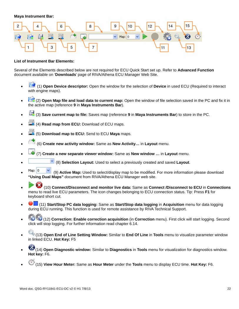
Maya Instrument Bar: List of Instrument Bar Elements: Several of the Elements described below are not required for ECU Quick Start set up. Refer to Advanced Function document available on ‘Downloads’ page of RIVA/Athena ECU Manager Web Site.
(1) Open Device descriptor: Open the window for the selection of Device in used ECU (Required to interact with engine maps).
(2) Open Map file and load data to current map: Open the window of file selection saved in the PC and fix it in the active map (reference 9 in Maya Instruments Bar).
(3) Save current map to file: Saves map (reference 9 in Maya Instruments Bar) to store in the PC.
(4) Read map from ECU: Download of ECU maps.
(5) Download map to ECU: Send to ECU Maya maps.
(6) Create new activity window: Same as New Activity… in Layout menu.
(7) Create a new separate viewer window: Same as New window … in Layout menu.
(8) Selection Layout: Used to select a previously created and saved Layout.
(9) Active Map: Used to select/display map to be modified. For more information please download “Using Dual Maps” document from RIVA/Athena ECU Manager web site.
(10) Connect/Disconnect and monitor live data: Same as Connect /Disconnect to ECU in Connections menu to read live ECU parameters. The icon changes belonging to ECU connection status. Tip: Press F1 for keyboard short cut.
(11) Start/Stop PC data logging: Same as Start/Stop data logging in Acquisition menu for data logging during ECU running. This function is used for remote assistance by RIVA Technical Support.
(12) Correction: Enable correction acquisition (in Correction menu). First click will start logging. Second click will stop logging. For further information read chapter 6.14.
(13) Open End of Line Setting Window: Similar to End Of Line in Tools menu to visualize parameter window in linked ECU. Hot Key: F5
(14) Open Diagnostic window: Similar to Diagnostics in Tools menu for visualization for diagnostics window. Hot key: F6.
(15) View Hour Meter: Same as Hour Meter under the Tools menu to display ECU time. Hot Key: F6.
1
2
3 5 7 13
94 6 8 12 15
11
10 14
Word doc. QSG-RY11841-ECU-DC v2 © H1 7/8/13 23
Section 10 – GLOSSARY
The following terms are used throughout this document.
Maya: The Athena software used to view and edit the values in the ECU.
Device file: Represents the firmware for the ECU. It is also how new 'Options are added to the ECU's functionality. This file is opened in Maya and is specific to the Make/Model of the water craft.
Map: This is your 'TUNE' or your configuration file. The 'Map' represents your fuel and ignition values. This file also holds all of the settings needed to run the engine.
EOL (End-Of-Line): Used to set specific values in the ECU for Throttle Calibration.
Normal Mode: This is the mode used for operating the ski under regular riding conditions.
Service Mode: This mode is used to allow the ECU to communicate with the PC while the Engine is 'OFF' and the ECU is 'ON'. This mode is most notably used for reading the base Map or setting the TPS.
Program Mode: This mode is used to send Maps to the ECU and change function parameters.
Advanced Functions: More detailed information for this function or feature can be found on the ‘Downloads’ page of our ECU Manager web site.


![OG 2017 - Athena Aftermarket Division · ENGINE CONTROL UNIT [ECU] • RX1 POWER • RX1 EVO BASIC ECU RACING KIT • RX1 EVO • PRO-FACTORY KIT ... Produttore leader di centraline](https://img.pdfslide.us/doc/110x75/5c5f5b0309d3f2581a8b458d/og-2017-athena-aftermarket-engine-control-unit-ecu-rx1-power-rx1.jpg)