Embed Size (px)
Citation preview

Quick Start Guide SABRE Platform for Smart Devices
Based on the i.MX 6 Series

2
Quick Start Guide
About the SABRE Platform for Smart Devices Based on the i.MX 6 Series
The Smart Application Blueprint for Rapid Engineering (SABRE) platform for smart devices is the latest in a series of high-performance, highly integrated development kits from Freescale that introduce designers to market-focused uses of the i.MX 6 series applications processor.
The SABRE platform for smart devices can be targeted towards any device requiring an intelligent display, connectivity, low power consumption and an amazing user experience, and comes equipped with either an i.MX 6Quad applications processor or an i.MX 6DualLite applications processor. Included with the design are links to the hardware design files, tools and board support packages (BSP) for Linux® and Android™ along with bootable Android image on an SD card to get you up and running quickly.

3
freescale.com
The following features are available with the SABRE platform for smart devices based on the i.MX 6 series:
• i.MX 6Quad applications processor 1 GHz or i.MX 6DualLite applications processor 1 GHz
• 1 GB DDR3 533 MHz
• 10" LVDS display panel with capacitive touch screen
• 8 GB eMMC iNAND
• Two SD card slots
• SATA 22-pin connector
• HDMI connector
• Secondary LVDS connector
• LCD expansion port connector
• EPDC expansion port connector
• Two five-megapixel cameras
• Two 3.5 mm audio ports (stereo HP and microphone)
• Two board-mounted digital microphones
• External stereo speakers
• 4 MB SPI NOR flash
• USB OTG connector
• Debug out via USB µAB device connector
• Gigabit Ethernet connector
• JTAG 20-pin connector
• mPCIe connector
• GPS module with antenna
• Sensor package including:
3-axis accelerometer
Digital compass
Ambient light sensor

4
Quick Start Guide
Get to Know SABRE Platform for Smart Devices Based on the i.MX 6 Series
External Speakers
U17–Ambient Light Sensor
GPS Antenna
U19–GPS Module
J11–MIPI Display Connector
CON2–DC Battery Connector
J5–MIPI Camera Connector
U14–SPI NOR Flash
No Manual SD Switch On SDP

5
freescale.com
P1–DC Power ConnectorCON1–SIM Card Connector
J1–Mini PCIe Connector
SW2–Board Reset Button
J7–Ethernet Connector
J9–DVP Camera Connector
U18–Accelerometer
U20–eCompass
J2–Headphone Output Jack
J4–Microphone Input Jack
SW1–Optional Power Button
SW4–Volume Up Button
SW5–Volume Down Button
J6–JTAG Connector
J8–HDMI Connector
SW6-Boot Mode Selector Switch
J13–Bluetooth® Cable Connector

6
Quick Start Guide
J504–LCD Expansion Port Connector
J506–22-Pin SATA Connector
J502–LVDS1 Connector
J503–LVDS0 Connector
BT500–Lithium Coin Cell Connector
CON500–External Speaker Connector
J509–Serial-To-USB Debug Port
J508–EPDC Expansion Port Connector
J507–SD3 Card Socket
J500–SD2 AUX SDIO Socket
J505–Micro USB Connector
7
freescale.com
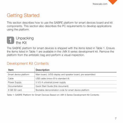
Getting Started This section describes how to use the SABRE platform for smart devices board and kit components. This section also describes the PC requirements to develop applications using the platform.
Item Description
Smart device platform Main board, LVDS display and speaker board, pre-assembled
Cable USB cable (micro-B to standard-A)
Power Supply 5 V/5 A universal power supply
Documentation Quick Start Guide (this document)
8 GB SD card Bootable demonstration code for smart device platform
Development Kit Contents
1 Unpacking the Kit
The SABRE platform for smart devices is shipped with the items listed in Table 1. Ensure the items listed in Table 1 are available in the i.MX 6 series development kit. Remove the platform from the antistatic bag and perform a visual inspection.
Table 1: SABRE Platform for Smart Devices Based on i.MX 6 Series Development Kit Contents

8
Quick Start Guide
“Jump Start Your Design” Contents
Download Software and ToolsDownload installation software and documentation under
“Jump Start Your Design” at freescale.com/SABRESDP. Table 2 lists the documents available on the kit website.
2
Item Description
SABRE platform for smart devices documentation
• Schematics, layout and Gerber files
• SABRE Platform for Smart Devices Based on the i.MX 6 Series Quick Start Guide (this document)
Software development tools Android and Linux BSPs
SABRE platform for smart devices demo images Copy of the Android image provided on the SD card
Table 2: “Jump Start Your Design” Contents
Getting Started

9
freescale.com
Setting Up the System
1 Insert SD Card
Insert the supplied SD card into socket SD3.
2 Connect USB Debug Cable (Optional)
Connect the micro-B end of the supplied USB cable into debug port J509. Connect the other end of the cable to a PC acting as a host terminal. If needed, the serial- to-USB drivers can be found at ftdichip.com/FTDrivers.htm.
Terminal window configuration: 115.2 kbaud, 8 data bits, 1 stop bit, no parity.
3 Connect Ethernet Cable (Optional)
Connect an Ethernet cable to the Ethernet jack J7.
4 Connect Power Supply
Connect the 5 V power supply cable to the 5 V DC power jack P1. When power is connected to the smart device, it will automatically begin the boot sequence.

10
Quick Start Guide
D1 D2 D3 D4 D5 D6 D7 D8
Off On Off Off Off Off On Off
Table 3: SABRE Platform for Smart Devices DIP Switch Configuration (SW6)
Boot Process for Android Image
1 Boot Process
Insert the supplied SD card into socket SD3.
• During the boot process, there will be operating system status information scrolling on the terminal window of the PC (if connected). The Linux penguin images will initially appear in the upper left corner of the display, one for each operating ARM® core.
• When the boot process is complete, the Android operating system will be displayed.
• To work from the terminal window on the host PC, press enter at the terminal window to get the command prompt.
DIP Switch Configuration (SW6)
11
freescale.com
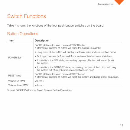
Switch Functions
Table 4 shows the functions of the four push button switches on the board.
Item Description
POWER SW1
SABRE platform for smart devices POWER button• Momentary depress of button will place the system in standby.
• Long press of the button will display a software drive shutdown option menu.
• Prolonged depress (> 5 sec.) will force an immediate hardware shutdown.
• If board is in the OFF state, momentary depress of button will restart (boot) the system.
• If board is in the STANDBY state, momentary depress of the button will bring the system out of standby (resume operations, no boot)
RESET SW2 SABRE platform for smart devices RESET button• Momentary depress of button will reset the system and begin a boot sequence.
Volume up SW4 Volume +
Volume down SW5 Volume -
Table 4: SABRE Platform for Smart Devices Button Operations
Button Operations

For more information, visit freescale.com/iMXSABRE
Freescale and the Freescale logo are trademarks of Freescale Semiconductor, Inc., Reg. U.S. Pat. & Tm. Off. All other product or service names are the property of their respective owners. ARM is a registered trademark of ARM Limited (or its subsidiaries) in the EU and/or elsewhere. All rights reserved. © 2012, 2014 Freescale Semiconductor, Inc.
Doc Number: IMX6QSDPQSG REV 1 Agile Number: 926-27392 REV B
SupportVisit the i.MX community at imxcommunity.org.
WarrantyVisit freescale.com/warranty for complete warranty information.
Get StartedDownload installation software and documentation under “Jump Start Your Design” at freescale.com/SABRESDP.