Embed Size (px)
Citation preview

Quick Start Guide
MT8870A Universal Wireless Test Set

1 MT8870A-E-T-1
Table of Contents
Table of Contents ................................................................................................................................... 1
1. Introduction ................................................................................................................................... 2
1.1. Checking Attachments ........................................................................................................ 2
1.2. Requirements for Setting-up MT8870A ............................................................................. 2
1.3. Terms .................................................................................................................................... 2
2. Initial Configuration ...................................................................................................................... 3
2.1. Hardware and Software Requirements ............................................................................. 3
2.2. Installing Run Time ............................................................................................................. 3
2.3. Installing MT8870A Configuration Software (Utility Tool) ............................................... 5
2.4. Changing PC Network Configuration ................................................................................ 5
2.5. Starting Instrument ............................................................................................................. 7
2.6. Starting Utility Tool .............................................................................................................. 7
2.7. Changing Network Settings ............................................................................................... 8
2.8. Changing GPIB settings ..................................................................................................... 9
2.9. Upgrading Firmware ......................................................................................................... 10
2.10. Installing Waveform File ................................................................................................... 12
2.11. Restoring PC Network Configuration .............................................................................. 12
3. Checking Operation ................................................................................................................... 13
3.1. Installing MT8870A Measurement Control Software (CombiView) .............................. 13
3.2. Checking Operation .......................................................................................................... 13
Starting CombiView ..................................................................................................... 13 3.2.1.
Checking Operation with Cellular Analysis License ................................................ 14 3.2.2.
Checking Operation with Short Range Wireless Analysis License ....................... 16 3.2.3.
4. Information about Product Registration .................................................................................. 18
4.1. If You Do Not Have Anritsu ID .......................................................................................... 18
4.2. Registering Product Information ..................................................................................... 20
4.3. Downloading ...................................................................................................................... 20

2 MT8870A-E-T-1
1. Introduction
This startup guide provides basic information on how to set up the MT8870A.
1.1. Checking Attachments
When unpacking, check that none of the products listed in the attached component list are missing.
1.2. Requirements for Setting-up MT8870A
Details
PC PC with Windows® XP or Windows
® 7 installed (details in section
2.1)
Ethernet cable Category 5, 5e, or 6 UTP cable
Both straight and cross cables supported
DVD MT8870A Universal
Wireless Test Set
Supplied accessory
Useful if you have
RF Cable RF cable with N-type connector (both ends)
Used in Chapter 3 Checking Operations.
1.3. Terms
The terms used in this guide are listed below.
Term Description
MT8870A Main unit
Up to four modules can be installed in the front of the unit.
This also refers to the whole unit including modules.
MU887000A Module installed in MT8870A.
This transmits and measures RF signals.
Chassis This refers to the MT8870A main frame and is used when it needs to be
distinguished from a module, such as on a menu screen.
3 MT8870A-E-T-1
2. Initial Configuration
Perform initial configuration for the MT8870A using the Utility Tool software.
The Utility Tool software is on the accessory DVD supplied with the MT8870A.
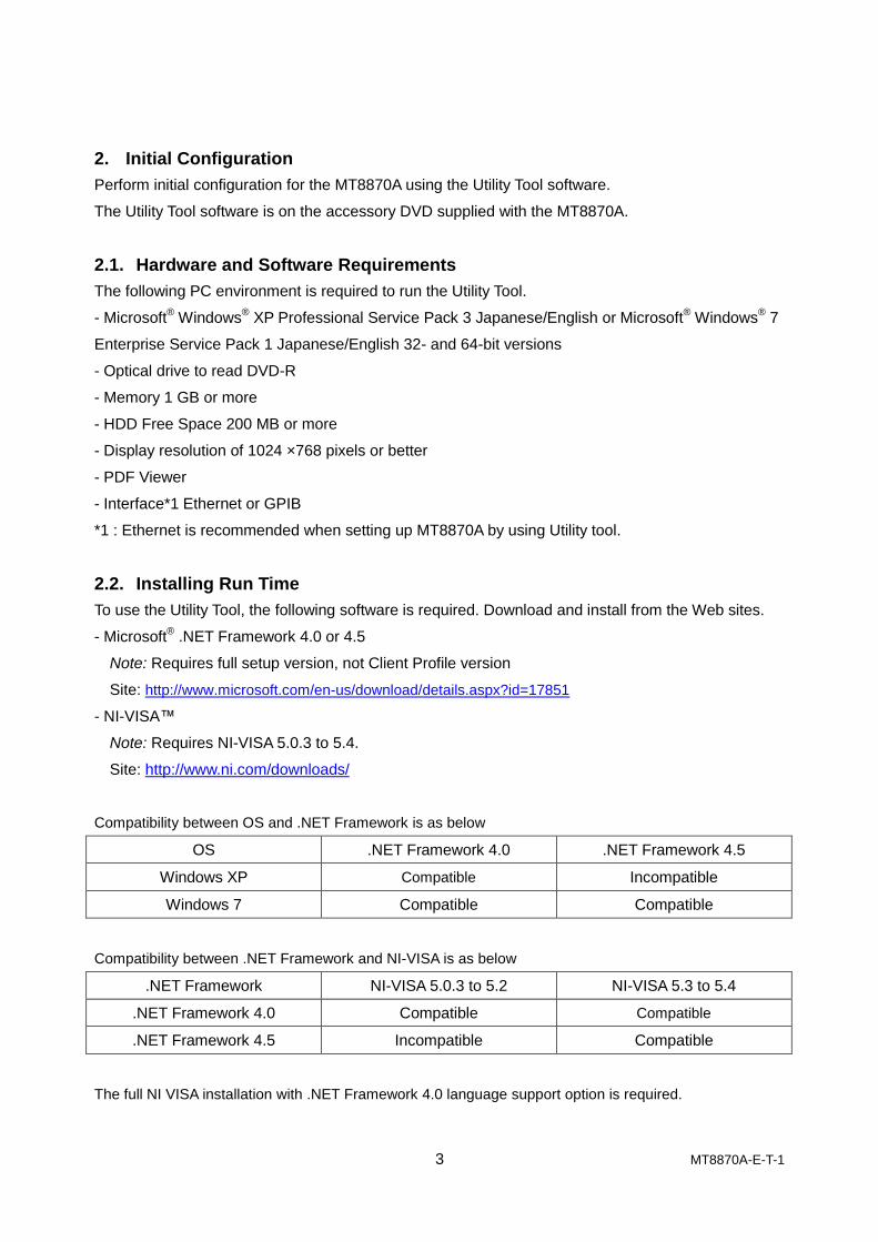
2.1. Hardware and Software Requirements
The following PC environment is required to run the Utility Tool.
- Microsoft® Windows
® XP Professional Service Pack 3 Japanese/English or Microsoft
® Windows
® 7
Enterprise Service Pack 1 Japanese/English 32- and 64-bit versions
- Optical drive to read DVD-R
- Memory 1 GB or more
- HDD Free Space 200 MB or more
- Display resolution of 1024 ×768 pixels or better
- PDF Viewer
- Interface*1 Ethernet or GPIB
*1 : Ethernet is recommended when setting up MT8870A by using Utility tool.
2.2. Installing Run Time
To use the Utility Tool, the following software is required. Download and install from the Web sites.
- Microsoft® .NET Framework 4.0 or 4.5
Note: Requires full setup version, not Client Profile version
Site: http://www.microsoft.com/en-us/download/details.aspx?id=17851
- NI-VISA™
Note: Requires NI-VISA 5.0.3 to 5.4.
Site: http://www.ni.com/downloads/
Compatibility between OS and .NET Framework is as below
OS .NET Framework 4.0 .NET Framework 4.5
Windows XP Compatible Incompatible
Windows 7 Compatible Compatible
Compatibility between .NET Framework and NI-VISA is as below
.NET Framework NI-VISA 5.0.3 to 5.2 NI-VISA 5.3 to 5.4
.NET Framework 4.0 Compatible Compatible
.NET Framework 4.5 Incompatible Compatible
The full NI VISA installation with .NET Framework 4.0 language support option is required.

4 MT8870A-E-T-1
Follow the procedure below when the NI software is already installed, but do not install the .NET 4.0
language support option.
Windows XP
1. Click Windows Control Panel > Add or Remove Programs.
2. Select the National Instruments Software and click Change/Remove.
3. Select NI-VISA 5.0.3 or newer version and click Modify to display the Window below.
Windows 7
1. Open the Windows Control Panel > Programs and Features.
2. Right-click National Instruments Software and click Uninstall/Change.
3. Select NI-VISA 5.0.3 or newer version and click Modify to display the following window.
Install .NET Framework 4.0 Language Support regardless of the version of the installed. NET
Framework.
5 MT8870A-E-T-1
2.3. Installing MT8870A Configuration Software (Utility Tool)
The Utility Tool installer and the operation manual are included on the DVD labeled MT8870A
Universal Wireless Test Set. Load this DVD into the optical drive of the PC.
Run setup.exe in the path /MT8870A/Installer/MT8870A Utility Tool/setup.exe on the DVD.
Follow the on-screen instructions to select the Utility Tool installation directory.
When installing NI-VISA 5.3, use Utility Tool v01.01.17 or newer.
Get the latest Utility Tool from the Anritsu Web site as described in Chapter 4.
2.4. Changing PC Network Configuration
The Utility Tool can control the MT8870A via both GPIB and Ethernet, but functions requiring file
transfer, such as updating firmware or installing waveform files can be used only with an Ethernet
connection. It is best to use an Ethernet connection when performing initial configuration even when
using GPIB control for system operation.
To control the MT8870A via Ethernet connection using the Utility Tool, the PC network configuration
must match the MT8870A network configuration.
If the PC is connected to a company network, disconnect the Ethernet cable from the PC.
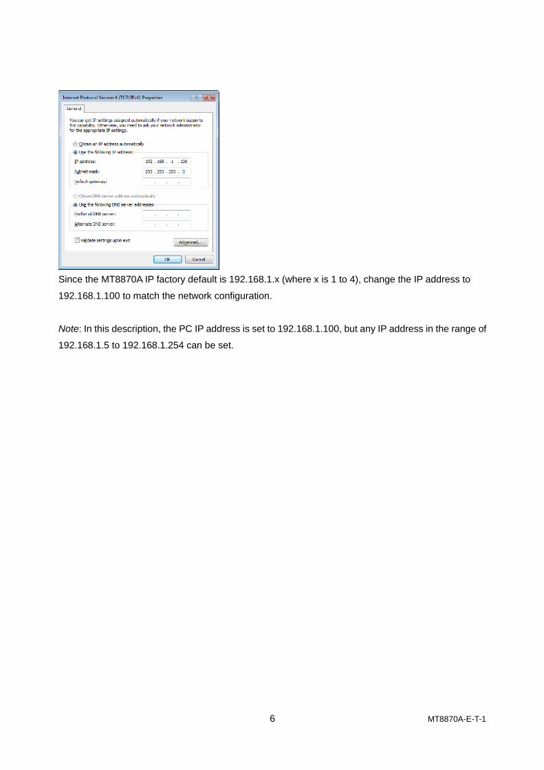
To set IP address:
Click Control Panel > Network and Sharing Center > Change adapter settings > Local Area
Connection > Properties > Internet Protocol Version 4(TCP/IPv4), and click Properties at the
Internet Protocol Version 4(TCP/IPv4) window.
6 MT8870A-E-T-1
Since the MT8870A IP factory default is 192.168.1.x (where x is 1 to 4), change the IP address to
192.168.1.100 to match the network configuration.
Note: In this description, the PC IP address is set to 192.168.1.100, but any IP address in the range of
192.168.1.5 to 192.168.1.254 can be set.

7 MT8870A-E-T-1
2.5. Starting Instrument
Connect the power cable to the MT8870A and press the Power button.
Connect the PC and MT8870A Ethernet connectors using an Ethernet cable.
The MT8870A has Ethernet connectors at front and back. Use either one.
2.6. Starting Utility Tool
Double-click the Utility Tool icon on the PC desktop.
Click IPv4 to display the Network interface selection screen showing the IP address configured in
section 2.4.
If the PC has two or more network interfaces, select the interface connected to the MT8870A.
8 MT8870A-E-T-1
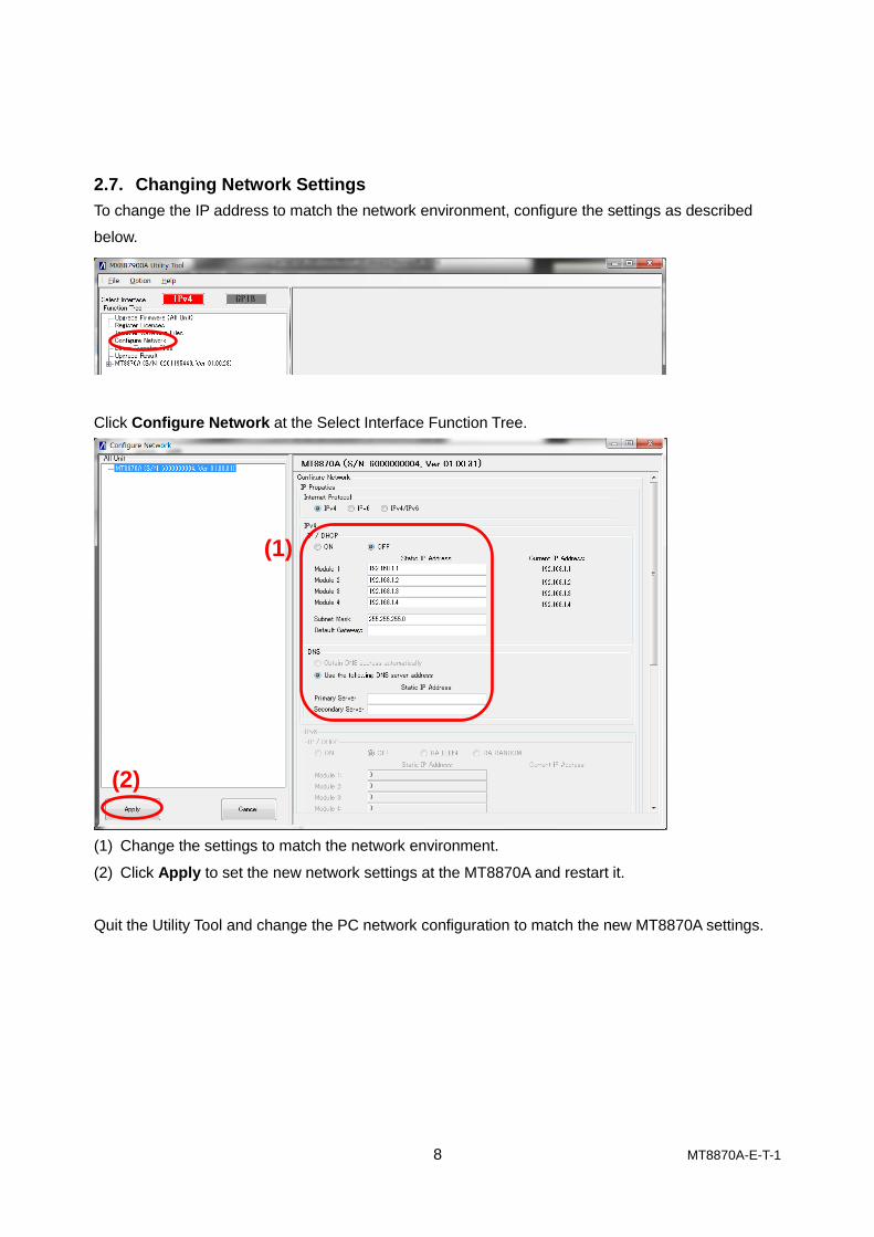
2.7. Changing Network Settings
To change the IP address to match the network environment, configure the settings as described
below.
Click Configure Network at the Select Interface Function Tree.
(1) Change the settings to match the network environment.
(2) Click Apply to set the new network settings at the MT8870A and restart it.
Quit the Utility Tool and change the PC network configuration to match the new MT8870A settings.
(1)
(2)
9 MT8870A-E-T-1
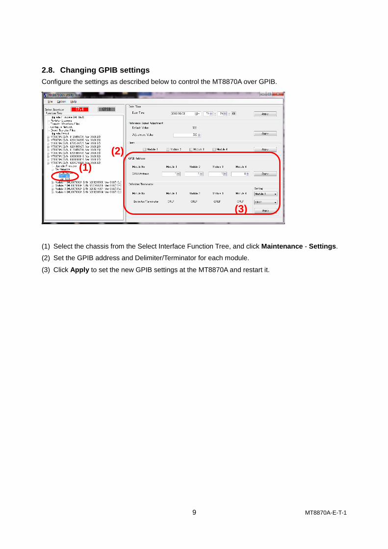
2.8. Changing GPIB settings
Configure the settings as described below to control the MT8870A over GPIB.
(1) Select the chassis from the Select Interface Function Tree, and click Maintenance - Settings.
(2) Set the GPIB address and Delimiter/Terminator for each module.
(3) Click Apply to set the new GPIB settings at the MT8870A and restart it.
(1)
(2)
(3)
10 MT8870A-E-T-1
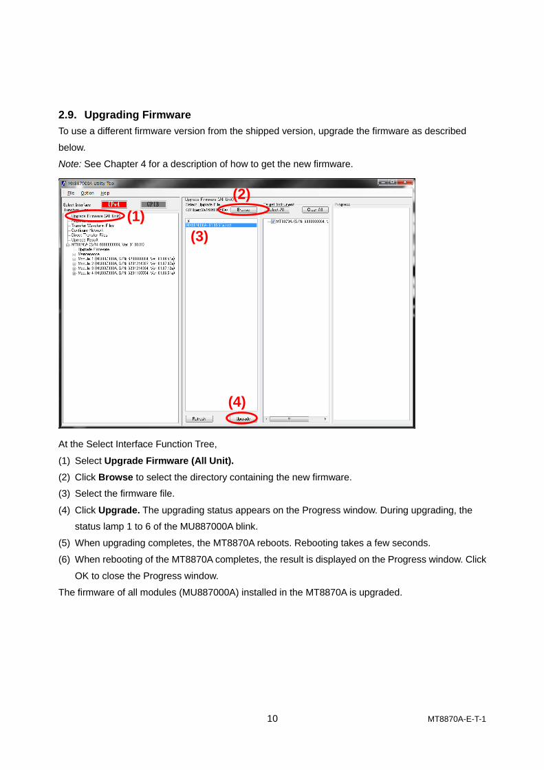
2.9. Upgrading Firmware
To use a different firmware version from the shipped version, upgrade the firmware as described
below.
Note: See Chapter 4 for a description of how to get the new firmware.
At the Select Interface Function Tree,
(1) Select Upgrade Firmware (All Unit).
(2) Click Browse to select the directory containing the new firmware.
(3) Select the firmware file.
(4) Click Upgrade. The upgrading status appears on the Progress window. During upgrading, the
status lamp 1 to 6 of the MU887000A blink.
(5) When upgrading completes, the MT8870A reboots. Rebooting takes a few seconds.
(6) When rebooting of the MT8870A completes, the result is displayed on the Progress window. Click
OK to close the Progress window.
The firmware of all modules (MU887000A) installed in the MT8870A is upgraded.
(1)
(2)
(3)
(4)

11 MT8870A-E-T-1
To upgrade the firmware for specific modules:
(1) Select the chassis and click Upgrade Firmware.
(2) Click Browse to select the directory containing the new firmware.
(3) Select the firmware file.
(4) Check/un-check the module(s) for firmware upgrading.
(5) Click Upgrade.
(1)
(2)
(3) (4)
(5)
12 MT8870A-E-T-1
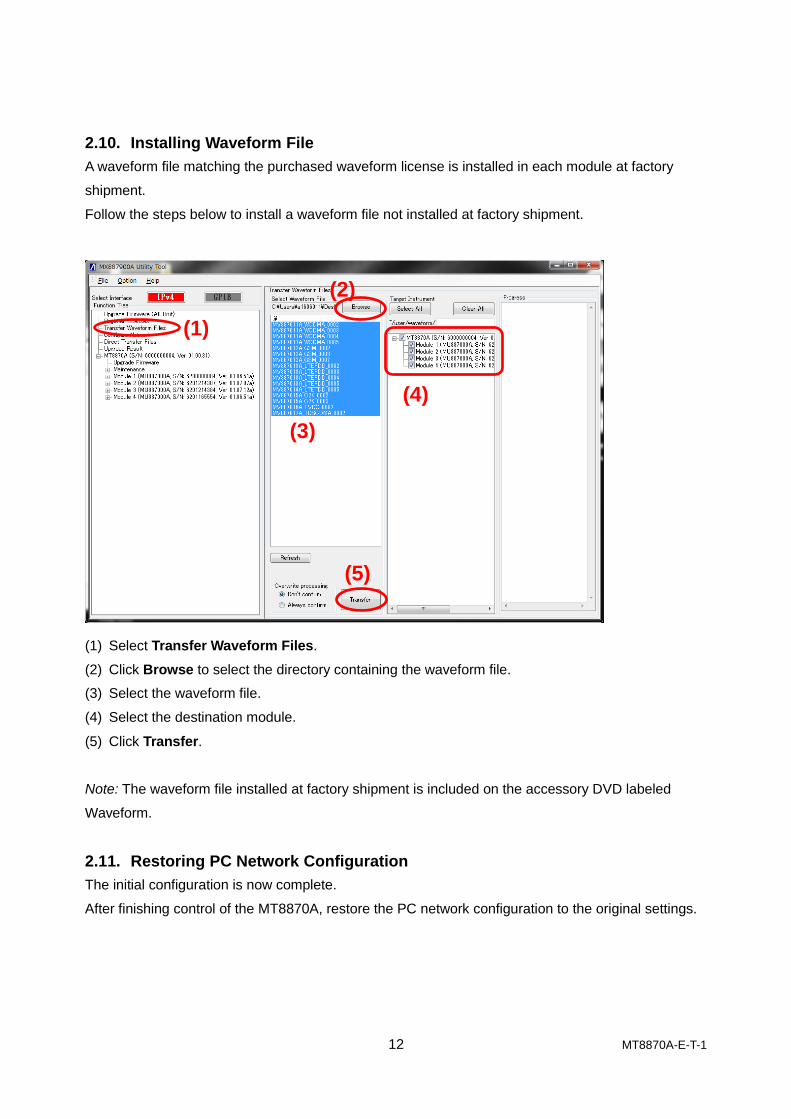
2.10. Installing Waveform File
A waveform file matching the purchased waveform license is installed in each module at factory
shipment.
Follow the steps below to install a waveform file not installed at factory shipment.
(1) Select Transfer Waveform Files.
(2) Click Browse to select the directory containing the waveform file.
(3) Select the waveform file.
(4) Select the destination module.
(5) Click Transfer.
Note: The waveform file installed at factory shipment is included on the accessory DVD labeled
Waveform.
2.11. Restoring PC Network Configuration
The initial configuration is now complete.
After finishing control of the MT8870A, restore the PC network configuration to the original settings.
(1)
(2)
(3)
(4)
(5)

13 MT8870A-E-T-1
3. Checking Operation
The MT8870A can be operated only by the remote commands described in the operation manual.
Remote commands related to analysis are described in each operation manual.
This section explains how to perform a simple operation check using the MT8870A control software
(CombiView) on the attached DVD.
3.1. Installing MT8870A Measurement Control Software (CombiView)
Run the installers in the folder MT8870A/Installer/CombiView/ on the accessory DVD. See Chapter 2
in the PDF document mx880052a_opm_e_xxx.pdf in the folder /MT8870A/Manual/English for the
installation instructions.
Install using this manual as a guide.
3.2. Checking Operation
Check the RF input and output by:
a) Outputting a CW signal using the Vector Signal Generator function.
b) Receiving the signal using the spectrum monitor function.
Connect an RF cable with N-type connector to Port3 and Port4 of the module.
Starting CombiView 3.2.1.
Double-click the CombiView icon on the PC desktop to start CombiView.

14 MT8870A-E-T-1
Checking Operation with Cellular Analysis License 3.2.2.
The procedure for checking the MT8870A when using the registered Cellular analysis software is
described below.
1) At the software selection screen, double-click Cellular - Common - Spectrum Monitor to display
the Spectrum Monitor screen.
2) Set the parameters shown below.
Next, configure the Vector Signal Generator.
Click Apply after configuring the Vector Signal Generator.
Spectrum monitor settings
Vector Signal Generator settings
Apply

15 MT8870A-E-T-1
3) Click the measurement execution button (triangle symbol) at the top of the screen to perform
measurement.
Check the displayed graph and confirm that the waveform has a peak.
This confirms RF signal output and measurement.
If the waveform does not have a peak, check the following:
- RF cables connected to correct port set at Input Port/Output Port at Spectrum Monitor screen
- Level and Frequency settings of Spectrum Monitor match settings of Vector Signal Generator
- Modulation of Vector Signal Generator set to Off
- Output of Vector Signal Generator set to On
The method for checking performance is described in Chapter 7 of the PDF document labeled
mu887000a_opm_e_xxx.pdf.
16 MT8870A-E-T-1
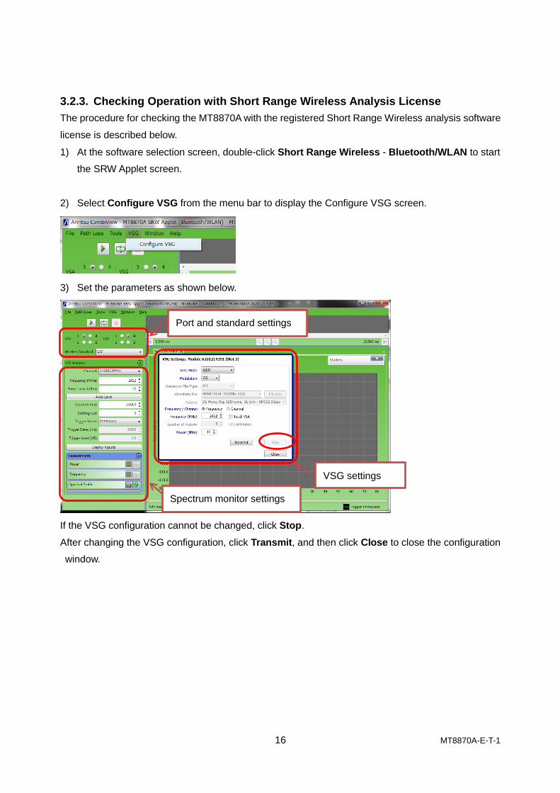
Checking Operation with Short Range Wireless Analysis License 3.2.3.
The procedure for checking the MT8870A with the registered Short Range Wireless analysis software
license is described below.
1) At the software selection screen, double-click Short Range Wireless - Bluetooth/WLAN to start
the SRW Applet screen.
2) Select Configure VSG from the menu bar to display the Configure VSG screen.
3) Set the parameters as shown below.
If the VSG configuration cannot be changed, click Stop.
After changing the VSG configuration, click Transmit, and then click Close to close the configuration
window.
Spectrum monitor settings
Port and standard settings
VSG settings

17 MT8870A-E-T-1
4) Click the measurement execution button (triangle symbol) at the top of the screen to perform
measurement.
Check the displayed graph and confirm that the waveform has a peak.
This confirms RF signal output and measurement.
If the waveform does not have a peak, check the following:
- RF cables connected to correct port set at VSA/VSG Port in SRW Applet screen
- Power and Frequency settings of CW Analysis match VSG settings
- Modulation of VSG set to CW
- RF signal output started (Click Transmit at the VSG screen to check this.)
The method for checking performance is described in Chapter 7 of the PDF document labeled
mu887000a_opm_e_xxx.pdf.
18 MT8870A-E-T-1
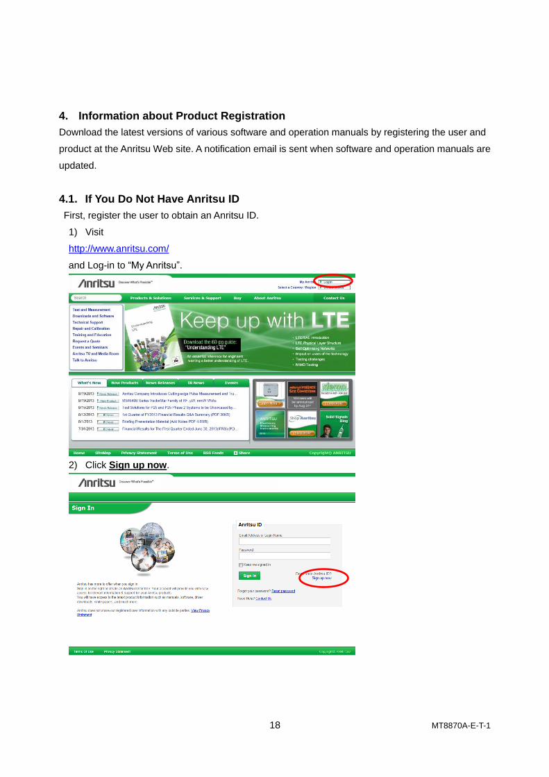
4. Information about Product Registration
Download the latest versions of various software and operation manuals by registering the user and
product at the Anritsu Web site. A notification email is sent when software and operation manuals are
updated.
4.1. If You Do Not Have Anritsu ID
First, register the user to obtain an Anritsu ID.
1) Visit
http://www.anritsu.com/
and Log-in to “My Anritsu”.
2) Click Sign up now.
19 MT8870A-E-T-1
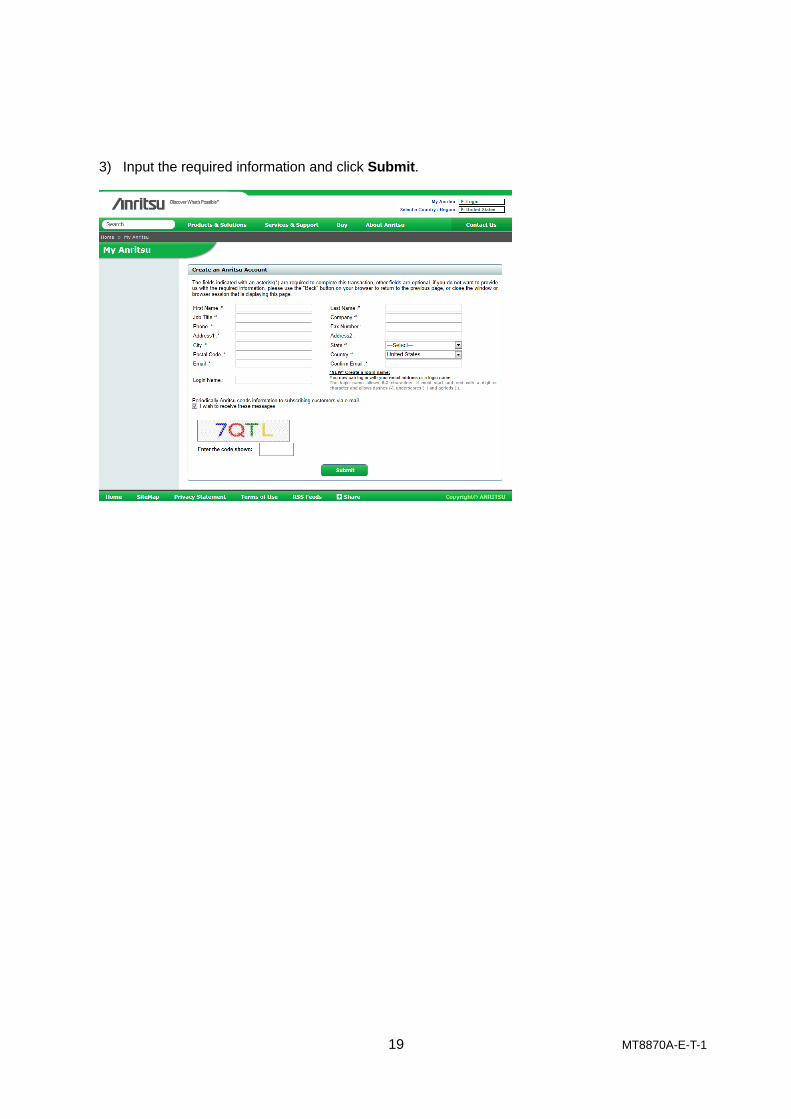
3) Input the required information and click Submit.

20 MT8870A-E-T-1
4.2. Registering Product Information
Log-in to the Anritsu Web site using the Anritsu ID and register the product information. If you do not
have an Anritsu ID, register for an Anritsu ID as described in section 4.1.
Go to http://www.anritsu.com/ and follow the steps listed below to register the purchased MT8870A.
Log-in to “My Anritsu” and Select Register My Product
Input the Model Number and Serial Number.
4.3. Downloading
The latest versions of software and operation manuals are available from the Anritsu Web site.
Navigate to the software download page shown below.
http://www.anritsu.com/
Log-in to “My Anritsu”.
Select My Registered Products.
> Click MT8870A - Software and Drivers View
> Click Software Download Service
> Download.

21 MT8870A-E-T-1
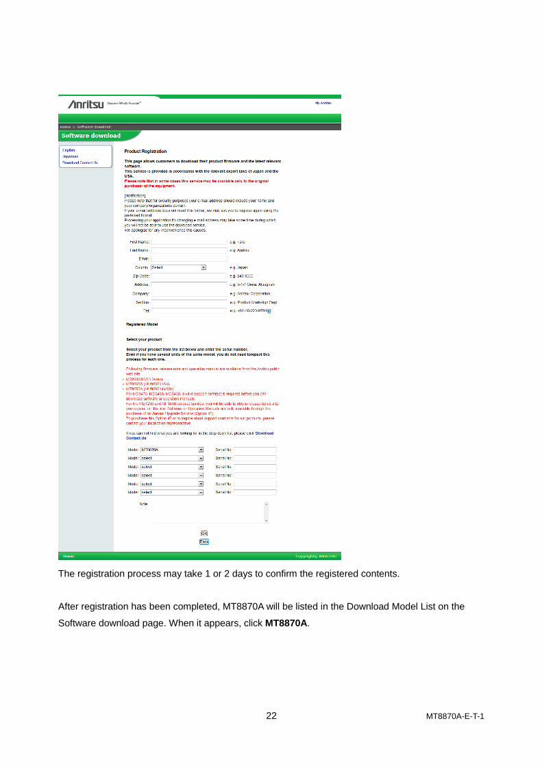
Register the Download Model at the first visit to the site.
Click Product Registration and input the information.
22 MT8870A-E-T-1
The registration process may take 1 or 2 days to confirm the registered contents.
After registration has been completed, MT8870A will be listed in the Download Model List on the
Software download page. When it appears, click MT8870A.

23 MT8870A-E-T-1
The latest versions of the operation manuals, firmware, and PC software are available for download
from here.

24 MT8870A-E-T-1
Trademarks and Registered Trademarks
Microsoft® and Windows
® are registered trademarks of Microsoft Corporation in the United States
and other countries.
NI-VISA™ is a trademark of National instruments Corporation.
• United StatesAnritsu Company1155 East Collins Blvd., Suite 100, Richardson, TX 75081, U.S.A.Toll Free: 1-800-267-4878Phone: +1-972-644-1777Fax: +1-972-671-1877
• CanadaAnritsu Electronics Ltd.700 Silver Seven Road, Suite 120, Kanata, Ontario K2V 1C3, CanadaPhone: +1-613-591-2003 Fax: +1-613-591-1006
• BrazilAnritsu Eletrônica Ltda.Praça Amadeu Amaral, 27 - 1 Andar01327-010 - Bela Vista - São Paulo - SP - BrazilPhone: +55-11-3283-2511Fax: +55-11-3288-6940
• MexicoAnritsu Company, S.A. de C.V.Av. Ejército Nacional No. 579 Piso 9, Col. Granada11520 México, D.F., MéxicoPhone: +52-55-1101-2370Fax: +52-55-5254-3147
• United KingdomAnritsu EMEA Ltd.200 Capability Green, Luton, Bedfordshire, LU1 3LU, U.K.Phone: +44-1582-433200 Fax: +44-1582-731303
• FranceAnritsu S.A.12 avenue du Québec, Bâtiment Iris 1- Silic 612,91140 VILLEBON SUR YVETTE, FrancePhone: +33-1-60-92-15-50Fax: +33-1-64-46-10-65
• GermanyAnritsu GmbHNemetschek Haus, Konrad-Zuse-Platz 1 81829 München, Germany Phone: +49-89-442308-0 Fax: +49-89-442308-55
• ItalyAnritsu S.r.l.Via Elio Vittorini 129, 00144 Roma, ItalyPhone: +39-6-509-9711 Fax: +39-6-502-2425
• SwedenAnritsu ABKistagången 20B, 164 40 KISTA, SwedenPhone: +46-8-534-707-00 Fax: +46-8-534-707-30
• FinlandAnritsu ABTeknobulevardi 3-5, FI-01530 VANTAA, FinlandPhone: +358-20-741-8100Fax: +358-20-741-8111
• DenmarkAnritsu A/SKay Fiskers Plads 9, 2300 Copenhagen S, DenmarkPhone: +45-7211-2200Fax: +45-7211-2210
• RussiaAnritsu EMEA Ltd. Representation Office in RussiaTverskaya str. 16/2, bld. 1, 7th floor.Russia, 125009, MoscowPhone: +7-495-363-1694Fax: +7-495-935-8962
• United Arab EmiratesAnritsu EMEA Ltd.Dubai Liaison OfficeP O Box 500413 - Dubai Internet CityAl Thuraya Building, Tower 1, Suit 701, 7th FloorDubai, United Arab EmiratesPhone: +971-4-3670352Fax: +971-4-3688460
• IndiaAnritsu India Private Limited2nd & 3rd Floor, #837/1, Binnamangla 1st Stage, Indiranagar, 100ft Road, Bangalore - 560038, IndiaPhone: +91-80-4058-1300Fax: +91-80-4058-1301
• SingaporeAnritsu Pte. Ltd.11 Chang Charn Road, #04-01, Shriro HouseSingapore 159640Phone: +65-6282-2400Fax: +65-6282-2533
• P.R. China (Shanghai)Anritsu (China) Co., Ltd.Room 2701-2705, Tower A, New Caohejing International Business CenterNo. 391 Gui Ping Road Shanghai, 200233, P.R. ChinaPhone: +86-21-6237-0898Fax: +86-21-6237-0899
• P.R. China (Hong Kong)Anritsu Company Ltd.Unit 1006-7, 10/F., Greenfield Tower, Concordia Plaza,No. 1 Science Museum Road, Tsim Sha Tsui East, Kowloon, Hong Kong, P.R. ChinaPhone: +852-2301-4980Fax: +852-2301-3545
• JapanAnritsu Corporation8-5, Tamura-cho, Atsugi-shi, Kanagawa, 243-0016 JapanPhone: +81-46-296-1221Fax: +81-46-296-1238
• KoreaAnritsu Corporation, Ltd.5FL, 235 Pangyoyeok-ro, Bundang-gu, Seongnam-si, Gyeonggi-do, 463-400 KoreaPhone: +82-31-696-7750Fax: +82-31-696-7751
• AustraliaAnritsu Pty. Ltd.Unit 21/270 Ferntree Gully Road, Notting Hill, Victoria 3168, AustraliaPhone: +61-3-9558-8177Fax: +61-3-9558-8255
• TaiwanAnritsu Company Inc.7F, No. 316, Sec. 1, NeiHu Rd., Taipei 114, TaiwanPhone: +886-2-8751-1816Fax: +886-2-8751-1817
Specifications are subject to change without notice.
1404
Printed on Recycled Paper
Please Contact:
Printed in Japan 2014-7 MG No.MT8870A-E-T-1-(2.00)