Embed Size (px)
Citation preview

33
Technical Design Guide issued by Forest and Wood Products Australia
Quick Connect Moment Connection

WoodSolutions is an industry initiative designed to provide independent, non-proprietary information about timber and wood products to professionals and companies involved in building design and construction.
WoodSolutions is resourced by Forest and Wood Products Australia (FWPA – www.fwpa.com.au). It is a collaborative effort between FWPA members and levy payers, supported by industry bodies and technical associations.
This work is supported by funding provided to FWPA by the Commonwealth Government.
ISBN 978-1-925213-31-7
Acknowledgments
Authors: Pierre Quenneville, Felix Scheibmair
The research and development forming the foundation of this Design Guide as well as its preparation and production was proudly made possible by the shareholders and financial partners of the Structural Timber Innovation Company Ltd.
First published: 2011 Revised: April 2016
WoodSolutions Technical Design Guides
A growing suite of information, technical and training resources, the Design Guides have been created to support the use of wood in the design and construction of the built environment.
Each title has been written by experts in the field and is the accumulated result of years of experience in working with wood and wood products.
Some of the popular topics covered by the Technical Design Guides include:
• Timber-framed construction• Building with timber in bushfire-prone areas• Designing for durability• Timber finishes• Stairs, balustrades and handrails• Timber flooring and decking• Timber windows and doors• Fire compliance• Acoustics• Thermal performance
More WoodSolutions Resources
The WoodSolutions website provides a comprehensive range of resources for architects, building designers, engineers and other design and construction professionals.
To discover more, please visit www.woodsolutions.com.au The website for wood.
01
Technical Design Guide issued by Forest and Wood Products Australia
Timber-framed Constructionfor Townhouse Buildings Class 1aDesign and construction guide for BCA compliant sound and fire-rated construction
04
Technical Design Guide issued by Forest and Wood Products Australia
Building with Timber in Bushfire-prone AreasBCA Compliant Design and Construction Guide
09
Technical Design Guide issued by Forest and Wood Products Australia
Timber FlooringDesign guide for installation
© 2016 Forest and Wood Products Australia Limited. All rights reserved.
These materials are published under the brand WoodSolutions by FWPA. This guide has been reviewed and updated for use in Australia by TDA NSW.
IMPORTANT NOTICE
While all care has been taken to ensure the accuracy of the information contained in this publication, Forest and Wood Products Australia Limited (FWPA) and WoodSolutions Australia and all persons associated with them as well as any other contributors make no representations or give any warranty regarding the use, suitability, validity, accuracy, completeness, currency or reliability of the information, including any opinion or advice, contained in this publication. To the maximum extent permitted by law, FWPA disclaims all warranties of any kind, whether express or implied, including but not limited to any warranty that the information is up-to-date, complete, true, legally compliant, accurate, non-misleading or suitable.
To the maximum extent permitted by law, FWPA excludes all liability in contract, tort (including negligence), or otherwise for any injury, loss or damage whatsoever (whether direct, indirect, special or consequential) arising out of or in connection with use or reliance on this publication (and any information, opinions or advice therein) and whether caused by any errors, defects, omissions or misrepresentations in this publication. Individual requirements may vary from those discussed in this publication and you are advised to check with State authorities to ensure building compliance as well as make your own professional assessment of the relevant applicable laws and Standards.
The work is copyright and protected under the terms of the Copyright Act 1968 (Cwth). All material may be reproduced in whole or in part, provided that it is not sold or used for commercial benefit and its source (Forest and Wood Products Australia Limited) is acknowledged and the above disclaimer is included. Reproduction or copying for other purposes, which is strictly reserved only for the owner or licensee of copyright under the Copyright Act, is prohibited without the prior written consent of FWPA.
WoodSolutions Australia is a registered business division of Forest and Wood Products Australia Limited.
Owing to copyright boundaries, this Guide must only be used in Australian States and Territories. Downloading or distributing this Guide or any of the materials therein in any other area is prohibited.
Cover image: Netball Central, Sydney Olympic Park, Architect: Scott Carver Photographer: Geoff Ambler
Page 3#33 • Quick Connect Moment Connection
Contents
1 Introduction 4
1.1 Quick-Connect Moment Connection ..............................................................................................4
1.2 Application ......................................................................................................................................6
2 Design of Quick-Connect Connection 7
2.1 Design Portal Frame Members Assuming the Joint is Rigid .........................................................7
2.2 Design of Connection Detail ...........................................................................................................7
2.2.1 Tension and Compression Forces in Joint ......................................................................................7
2.2.2 Design of Sleeves ...........................................................................................................................8
2.2.3 Design of Screws ............................................................................................................................9
2.2.4 Check Block Tear-Out Resistance in Main Portal Member ...........................................................12
2.2.5 Bearing Plate Design ....................................................................................................................13
2.2.6 Rod Design ...................................................................................................................................14
2.3 Evaluation of Rotational Stiffness ..................................................................................................14
2.4 Return to Step 1 ............................................................................................................................15
2.5 Adjust Member Sizes and Connection Design Accordingly .........................................................16
3 Quick-Connect Moment Connect Flow Chart 17
4 Design Example 18
4.1 Design Actions ..............................................................................................................................18
4.2 Sleeve Design ...............................................................................................................................18
4.3 Screw Design ................................................................................................................................19
4.4 Check Block Tear-Out Resistance in Portal Frame Members .......................................................20
4.5 Bearing Plate Design ....................................................................................................................21
4.6 Rod Design ...................................................................................................................................22
4.7 Joint Rotation ................................................................................................................................22
4.8 Apply Rotational Stiffness and Re-Check Member Sizes and Connection Strength ...................23
References 25
Appendix A – Notation 26
Page 4#33 • Quick Connect Moment Connection
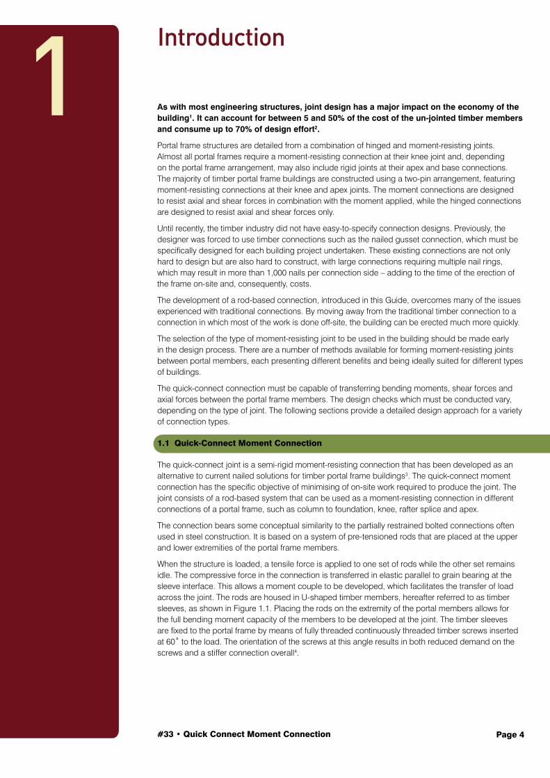
As with most engineering structures, joint design has a major impact on the economy of the building1. It can account for between 5 and 50% of the cost of the un-jointed timber members and consume up to 70% of design effort2.
Portal frame structures are detailed from a combination of hinged and moment-resisting joints. Almost all portal frames require a moment-resisting connection at their knee joint and, depending on the portal frame arrangement, may also include rigid joints at their apex and base connections. The majority of timber portal frame buildings are constructed using a two-pin arrangement, featuring moment-resisting connections at their knee and apex joints. The moment connections are designed to resist axial and shear forces in combination with the moment applied, while the hinged connections are designed to resist axial and shear forces only.
Until recently, the timber industry did not have easy-to-specify connection designs. Previously, the designer was forced to use timber connections such as the nailed gusset connection, which must be specifically designed for each building project undertaken. These existing connections are not only hard to design but are also hard to construct, with large connections requiring multiple nail rings, which may result in more than 1,000 nails per connection side – adding to the time of the erection of the frame on-site and, consequently, costs.
The development of a rod-based connection, introduced in this Guide, overcomes many of the issues experienced with traditional connections. By moving away from the traditional timber connection to a connection in which most of the work is done off-site, the building can be erected much more quickly.
The selection of the type of moment-resisting joint to be used in the building should be made early in the design process. There are a number of methods available for forming moment-resisting joints between portal members, each presenting different benefits and being ideally suited for different types of buildings.
The quick-connect connection must be capable of transferring bending moments, shear forces and axial forces between the portal frame members. The design checks which must be conducted vary, depending on the type of joint. The following sections provide a detailed design approach for a variety of connection types.
1.1 Quick-Connect Moment Connection
The quick-connect joint is a semi-rigid moment-resisting connection that has been developed as an alternative to current nailed solutions for timber portal frame buildings3. The quick-connect moment connection has the specific objective of minimising of on-site work required to produce the joint. The joint consists of a rod-based system that can be used as a moment-resisting connection in different connections of a portal frame, such as column to foundation, knee, rafter splice and apex.
The connection bears some conceptual similarity to the partially restrained bolted connections often used in steel construction. It is based on a system of pre-tensioned rods that are placed at the upper and lower extremities of the portal frame members.
When the structure is loaded, a tensile force is applied to one set of rods while the other set remains idle. The compressive force in the connection is transferred in elastic parallel to grain bearing at the sleeve interface. This allows a moment couple to be developed, which facilitates the transfer of load across the joint. The rods are housed in U-shaped timber members, hereafter referred to as timber sleeves, as shown in Figure 1.1. Placing the rods on the extremity of the portal members allows for the full bending moment capacity of the members to be developed at the joint. The timber sleeves are fixed to the portal frame by means of fully threaded continuously threaded timber screws inserted at 60˚ to the load. The orientation of the screws at this angle results in both reduced demand on the screws and a stiffer connection overall4.
Introduction
1
#33 • Quick Connect Moment Connection Page 5
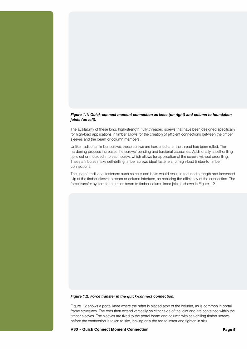
Figure 1.1: Quick-connect moment connection as knee (on right) and column to foundation joints (on left).
The availability of these long, high-strength, fully threaded screws that have been designed specifically for high-load applications in timber allows for the creation of efficient connections between the timber sleeves and the beam or column members.
Unlike traditional timber screws, these screws are hardened after the thread has been rolled. The hardening process increases the screws’ bending and torsional capacities. Additionally, a self-drilling tip is cut or moulded into each screw, which allows for application of the screws without predrilling. These attributes make self-drilling timber screws ideal fasteners for high-load timber-to-timber connections.
The use of traditional fasteners such as nails and bolts would result in reduced strength and increased slip at the timber sleeve to beam or column interface, so reducing the efficiency of the connection. The force transfer system for a timber beam to timber column knee joint is shown in Figure 1.2.
Figure 1.2: Force transfer in the quick-connect connection.
Figure 1.2 shows a portal knee where the rafter is placed atop of the column, as is common in portal frame structures. The rods then extend vertically on either side of the joint and are contained within the timber sleeves. The sleeves are fixed to the portal beam and column with self-drilling timber screws before the connection is taken to site, leaving only the rod to insert and tighten in situ.
#33 • Quick Connect Moment Connection Page 6
Because of the limited components that are required to form the connection, it is easily adapted for use in all parts of the structure. The basic connection configuration always remains the same.
Forces are transferred between the steel rods and the timber sleeves through a steel plate that bears laterally onto the end grain of the timber sleeve. It is also possible to transfer shear forces across the joint in this way; however, for ease of construction, the simplest method for transferring shear is to include dowels between the underside of the portal rafter and the top of the column.
The tolerances for the shear connection must be tighter than those for the long tension rods to ensure that the tension rods are not subjected to shear loading. In practical terms, the connection can be designed and manufactured without special training.
The timber sleeves and bearing block can all be pre-fastened to the portal frame member in a factory environment away from the construction site. This leaves only the rods and steel end bearing plates to be added on site and fastened with nuts. The onsite time required to produce the connection is minimal, saving labour and cranage time during erection and therefore construction costs.
1.2 Application
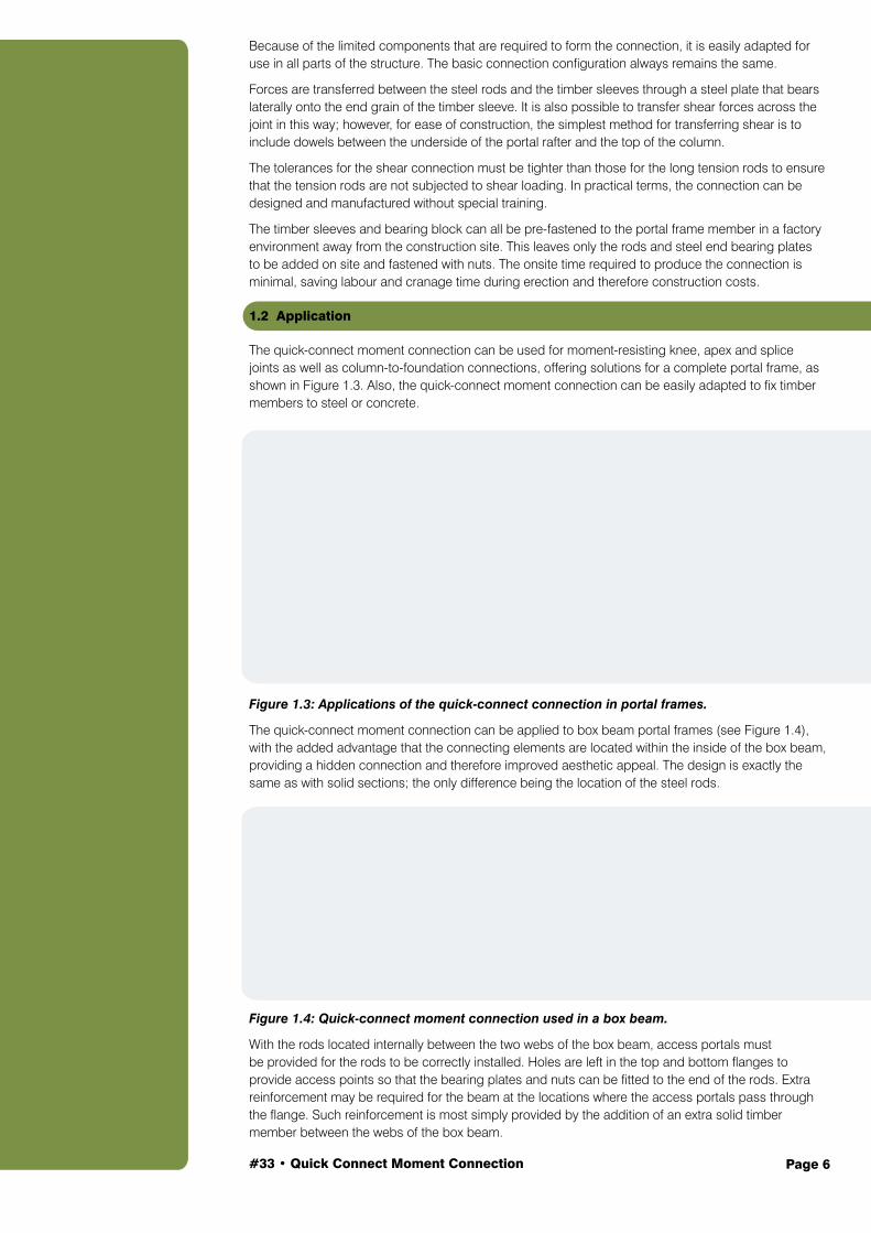
The quick-connect moment connection can be used for moment-resisting knee, apex and splice joints as well as column-to-foundation connections, offering solutions for a complete portal frame, as shown in Figure 1.3. Also, the quick-connect moment connection can be easily adapted to fix timber members to steel or concrete.
Figure 1.3: Applications of the quick-connect connection in portal frames.
The quick-connect moment connection can be applied to box beam portal frames (see Figure 1.4), with the added advantage that the connecting elements are located within the inside of the box beam, providing a hidden connection and therefore improved aesthetic appeal. The design is exactly the same as with solid sections; the only difference being the location of the steel rods.
Figure 1.4: Quick-connect moment connection used in a box beam.
With the rods located internally between the two webs of the box beam, access portals must be provided for the rods to be correctly installed. Holes are left in the top and bottom flanges to provide access points so that the bearing plates and nuts can be fitted to the end of the rods. Extra reinforcement may be required for the beam at the locations where the access portals pass through the flange. Such reinforcement is most simply provided by the addition of an extra solid timber member between the webs of the box beam.
#33 • Quick Connect Moment Connection Page 7
Design of Quick-Connect Connection
The quick-connect design procedure consists of an iterative process that is used to determine the required characteristics for the sleeves, main tension rods, screws and bearing plates. The connection is designed to resist a given moment; after the components have been specified, joint rotation can be determined.
The design method only relates to the timber-to-timber portal knee connection. The process can easily be adapted for other connection areas such as the column base, beam splice and apex connection.
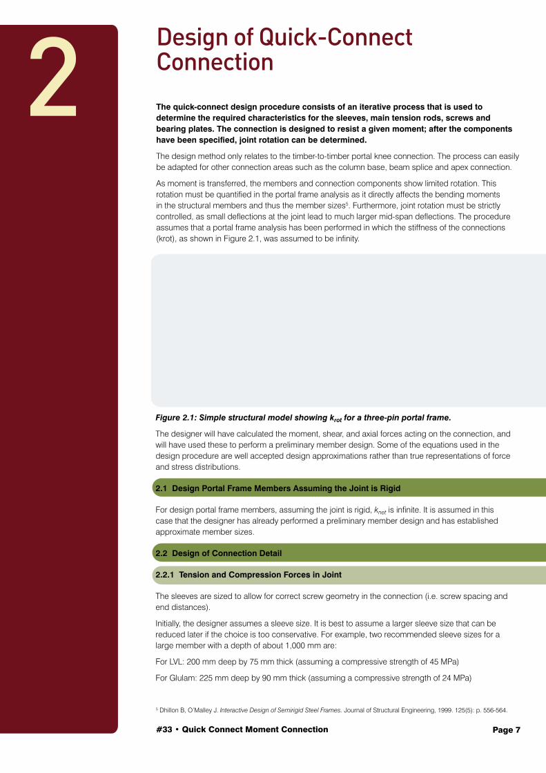
As moment is transferred, the members and connection components show limited rotation. This rotation must be quantified in the portal frame analysis as it directly affects the bending moments in the structural members and thus the member sizes5. Furthermore, joint rotation must be strictly controlled, as small deflections at the joint lead to much larger mid-span deflections. The procedure assumes that a portal frame analysis has been performed in which the stiffness of the connections (krot), as shown in Figure 2.1, was assumed to be infinity.
2
Figure 2.1: Simple structural model showing krot for a three-pin portal frame.
The designer will have calculated the moment, shear, and axial forces acting on the connection, and will have used these to perform a preliminary member design. Some of the equations used in the design procedure are well accepted design approximations rather than true representations of force and stress distributions.
2.1 Design Portal Frame Members Assuming the Joint is Rigid
For design portal frame members, assuming the joint is rigid, knet is infinite. It is assumed in this case that the designer has already performed a preliminary member design and has established approximate member sizes.
2.2 Design of Connection Detail
2.2.1 Tension and Compression Forces in Joint
The sleeves are sized to allow for correct screw geometry in the connection (i.e. screw spacing and end distances).
Initially, the designer assumes a sleeve size. It is best to assume a larger sleeve size that can be reduced later if the choice is too conservative. For example, two recommended sleeve sizes for a large member with a depth of about 1,000 mm are:
For LVL: 200 mm deep by 75 mm thick (assuming a compressive strength of 45 MPa)
For Glulam: 225 mm deep by 90 mm thick (assuming a compressive strength of 24 MPa)
5 Dhillon B, O’Malley J. Interactive Design of Semirigid Steel Frames. Journal of Structural Engineering, 1999. 125(5): p. 556-564.
#33 • Quick Connect Moment Connection Page 8
Design the sleeves to resist the compression force applied to their end grain. To determine the applied compression force, the moment arm, jd of the rods needs to be calculated as follows:
(2-1)
where
jd moment arm between the steel rods, as shown in Figure 1.2
d depth of member
e distance from the extreme fibre to the centre of the rod, as shown in Figure 1.2.
Equation (2-2) allows preliminary tension and compression forces to be calculated for each set of rods. One set of the rods will act in tension, whilst the other set will not have any load applied. This loading is reversed when the applied force direction is reversed. The sleeves are sized for axial compression loads resulting from the applied moment as well as the tension force in the member. The force per rod is then calculated from:
(2-2)
2.2.2 Design of Sleeves
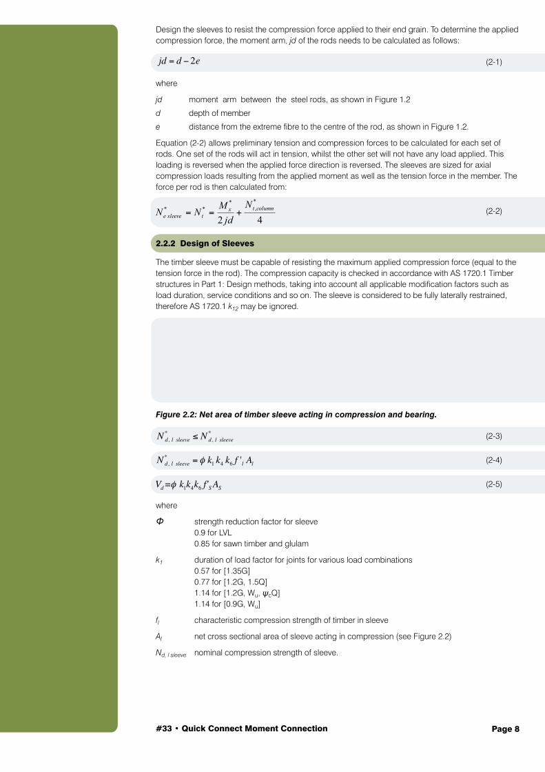
The timber sleeve must be capable of resisting the maximum applied compression force (equal to the tension force in the rod). The compression capacity is checked in accordance with AS 1720.1 Timber structures in Part 1: Design methods, taking into account all applicable modification factors such as load duration, service conditions and so on. The sleeve is considered to be fully laterally restrained, therefore AS 1720.1 k12 may be ignored.
Figure 2.2: Net area of timber sleeve acting in compression and bearing.
(2-3)
(2-4)
(2-5)
where
Φ strength reduction factor for sleeve 0.9 for LVL 0.85 for sawn timber and glulam
k1 duration of load factor for joints for various load combinations 0.57 for [1.35G] 0.77 for [1.2G, 1.5Q] 1.14 for [1.2G, Wu, ψcQ] 1.14 for [0.9G, Wu]
fl characteristic compression strength of timber in sleeve
Al net cross sectional area of sleeve acting in compression (see Figure 2.2)
Nd, l sleeve nominal compression strength of sleeve.
jd = d − 2e
N *d, l sleeve ≤ N *
d, l sleeve
N *d, l sleeve = φ k1 k4 k6 f 'l Al
Vd =φ k1k4k6 f'S AS
42
*,
*** columntxtsleevee
Njd
MNN
#33 • Quick Connect Moment Connection Page 9
2.2.3 Design of Screws
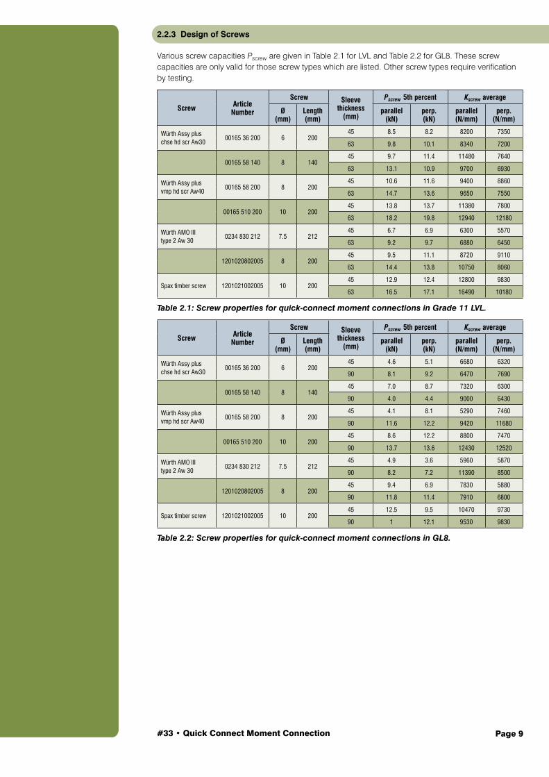
Various screw capacities Pscrew are given in Table 2.1 for LVL and Table 2.2 for GL8. These screw capacities are only valid for those screw types which are listed. Other screw types require verification by testing.
Screw Article Number
Screw Sleeve thickness
(mm)
Pscrew 5th percent Kscrew average
Ø (mm)
Length (mm)
parallel (kN)
perp. (kN)
parallel (N/mm)
perp. (N/mm)
Würth Assy plus chse hd scr Aw30
00165 36 200 6 20045 8.5 8.2 8200 7350
63 9.8 10.1 8340 7200
00165 58 140 8 14045 9.7 11.4 11480 7640
63 13.1 10.9 9700 6930
Würth Assy plus vmp hd scr Aw40
00165 58 200 8 20045 10.6 11.6 9400 8860
63 14.7 13.6 9650 7550
00165 510 200 10 20045 13.8 13.7 11380 7800
63 18.2 19.8 12940 12180
Würth AMO III type 2 Aw 30
0234 830 212 7.5 21245 6.7 6.9 6300 5570
63 9.2 9.7 6880 6450
1201020802005 8 20045 9.5 11.1 8720 9110
63 14.4 13.8 10750 8060
Spax timber screw 1201021002005 10 20045 12.9 12.4 12800 9830
63 16.5 17.1 16490 10180
Table 2.1: Screw properties for quick-connect moment connections in Grade 11 LVL.
Screw Article Number
Screw Sleeve thickness
(mm)
Pscrew 5th percent Kscrew average
Ø (mm)
Length (mm)
parallel (kN)
perp. (kN)
parallel (N/mm)
perp. (N/mm)
Würth Assy plus chse hd scr Aw30
00165 36 200 6 20045 4.6 5.1 6680 6320
90 8.1 9.2 6470 7690
00165 58 140 8 14045 7.0 8.7 7320 6300
90 4.0 4.4 9000 6430
Würth Assy plus vmp hd scr Aw40
00165 58 200 8 20045 4.1 8.1 5290 7460
90 11.6 12.2 9420 11680
00165 510 200 10 20045 8.6 12.2 8800 7470
90 13.7 13.6 12430 12520
Würth AMO III type 2 Aw 30
0234 830 212 7.5 21245 4.9 3.6 5960 5870
90 8.2 7.2 11390 8500
1201020802005 8 20045 9.4 6.9 7830 5880
90 11.8 11.4 7910 6800
Spax timber screw 1201021002005 10 20045 12.5 9.5 10470 9730
90 1 12.1 9530 9830
Table 2.2: Screw properties for quick-connect moment connections in GL8.
#33 • Quick Connect Moment Connection Page 10
To obtain the number of screws required to resist the tension and compression forces at each timber sleeve, the following equation is used:
ns = (2-6)
where
Φ strength reduction factor for sleeve 0.9 for LVL 0.85 for sawn timber and glulam
k1 duration of load factor for joints for various load combinations 0.57 for [1.35G] 0.77 for [1.2G, 1.5Q] 1.14 for [1.2G, Wu, ψcQ] 1.14 for [0.9G, Wu]
ns number of screws per sleeve required to resist tension forces in the connection
N*t,rod tension force carried by each steel rod
Pscrew 5th percentile strength of a single screw as given in the Table 2.1 for LVL and Table 2.2 for GL8.
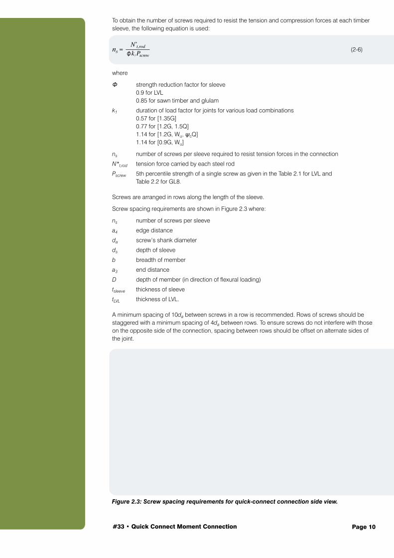
Screws are arranged in rows along the length of the sleeve.
Screw spacing requirements are shown in Figure 2.3 where:
ns number of screws per sleeve
a4 edge distance
da screw’s shank diameter
ds depth of sleeve
b breadth of member
a3 end distance
D depth of member (in direction of flexural loading)
tsleeve thickness of sleeve
tLVL thickness of LVL.
A minimum spacing of 10da between screws in a row is recommended. Rows of screws should be staggered with a minimum spacing of 4da between rows. To ensure screws do not interfere with those on the opposite side of the connection, spacing between rows should be offset on alternate sides of the joint.
Figure 2.3: Screw spacing requirements for quick-connect connection side view.
N*t,rod
Φ k1 Pscrew
#33 • Quick Connect Moment Connection Page 11
Figure 2.4: End distance.
The characteristic load capacity of the screws varies, depending on whether they are installed parallel or perpendicular to the grain. This is particularly important in knee joints, as different numbers of screws may be required in the portal rafter and column members.
Possible knee joint configurations are shown in Figure 2.5. The extent of the difference in parallel- and perpendicular-to-grain screw strengths also depends on the type of screws used.
Figure 2.5: Quick-connect moment connection knee joint configurations.
Figure 2.6: Combined shear and tearing in portal frame rafter.
#33 • Quick Connect Moment Connection Page 12
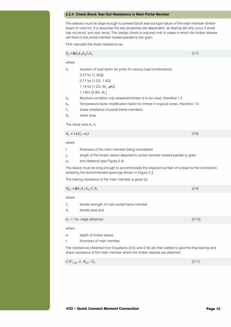
2.2.4 Check Block Tear-Out Resistance in Main Portal Member
The sleeves must be large enough to prevent block tear-out type failure of the main member (timber beam or column). It is assumed the two properties are dependent, as tearing will only occur if shear has occurred, and vice versa. This design check is required only in cases in which the timber sleeves are fixed to the portal member loaded parallel to the grain.
First calculate the shear resistance as:
Vd =Φ k1k4k6 f'sAs (2-7)
where
k1 duration of load factor for joints for various load combinations
0.57 for [1.35G]
0.77 for [1.2G, 1.5Q]
1.14 for [1.2G, Wu, ψQ]
1.14for [0.9G, Wu]
k4 Moisture condition only seasoned timber is to be used, therefore 1.0
k6 Temperature factor modification factor for timber in tropical zones, therefore 1.0
f’s shear resistance of portal frame members
As shear area.
The shear area As is:
As = t x (ls– a3) (2-8)
where
t thickness of the main member being considered
Is length of the timber sleeve attached to portal member loaded parallel to grain
a3 end distance (see Figure 2.4).
The sleeve must be long enough to accommodate the required number of screws for the connection, adopting the recommended spacings shown in Figure 2.3.
The tearing resistance of the main member is given by:
Nd,t =Φ k1 k4 k6 f 't At (2-9)
where
f’t tensile strength of main portal frame member
At tensile area and
At = t (w- edge distance) (2-10)
where
w depth of timber sleeve
t thickness of main member.
The resistances obtained from Equations (2-6) and (2-8) are then added to give the final tearing and shear resistance of the main member where the timber sleeves are attached:
2 N*t rod ≤ Nd,t + Vd (2-11)
#33 • Quick Connect Moment Connection Page 13
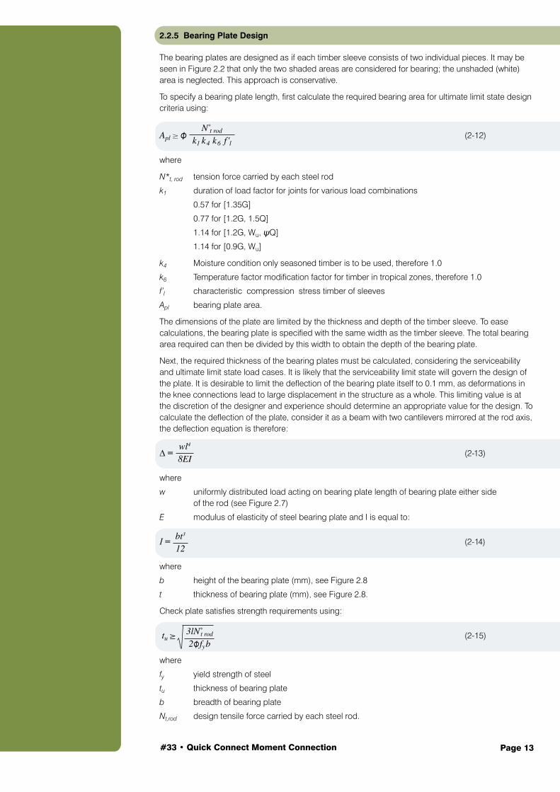
2.2.5 Bearing Plate Design
The bearing plates are designed as if each timber sleeve consists of two individual pieces. It may be seen in Figure 2.2 that only the two shaded areas are considered for bearing; the unshaded (white) area is neglected. This approach is conservative.
To specify a bearing plate length, first calculate the required bearing area for ultimate limit state design criteria using:
Apl ≥ Φ (2-12)
where
N*t, rod tension force carried by each steel rod
k1 duration of load factor for joints for various load combinations
0.57 for [1.35G]
0.77 for [1.2G, 1.5Q]
1.14 for [1.2G, Wu, ψQ]
1.14 for [0.9G, Wu]
k4 Moisture condition only seasoned timber is to be used, therefore 1.0
k6 Temperature factor modification factor for timber in tropical zones, therefore 1.0
f’l characteristic compression stress timber of sleeves
Apl bearing plate area.
The dimensions of the plate are limited by the thickness and depth of the timber sleeve. To ease calculations, the bearing plate is specified with the same width as the timber sleeve. The total bearing area required can then be divided by this width to obtain the depth of the bearing plate.
Next, the required thickness of the bearing plates must be calculated, considering the serviceability and ultimate limit state load cases. It is likely that the serviceability limit state will govern the design of the plate. It is desirable to limit the deflection of the bearing plate itself to 0.1 mm, as deformations in the knee connections lead to large displacement in the structure as a whole. This limiting value is at the discretion of the designer and experience should determine an appropriate value for the design. To calculate the deflection of the plate, consider it as a beam with two cantilevers mirrored at the rod axis, the deflection equation is therefore:
∆ = (2 -13)
where
w uniformly distributed load acting on bearing plate length of bearing plate either side of the rod (see Figure 2.7)
E modulus of elasticity of steel bearing plate and I is equal to:
I = (2-14)
where
b height of the bearing plate (mm), see Figure 2.8
t thickness of bearing plate (mm), see Figure 2.8.
Check plate satisfies strength requirements using:
tu ≥ (2-15)
where
fy yield strength of steel
tu thickness of bearing plate
b breadth of bearing plate
Nt,rod design tensile force carried by each steel rod.
N*t rod
k1 k4 k6 f 'l
wl4
8EI
bt3
12
3lN*t rod
2Φ fyb
#33 • Quick Connect Moment Connection Page 14
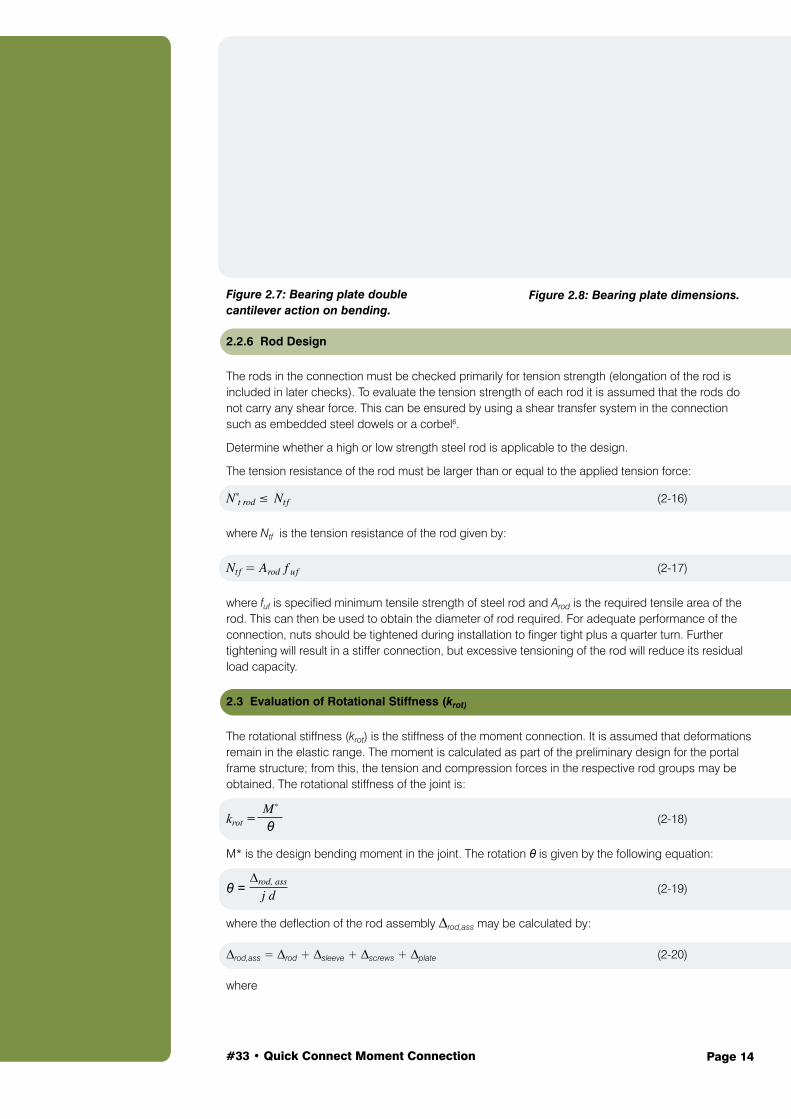
Figure 2.7: Bearing plate double cantilever action on bending.
2.2.6 Rod Design
The rods in the connection must be checked primarily for tension strength (elongation of the rod is included in later checks). To evaluate the tension strength of each rod it is assumed that the rods do not carry any shear force. This can be ensured by using a shear transfer system in the connection such as embedded steel dowels or a corbel6.
Determine whether a high or low strength steel rod is applicable to the design.
The tension resistance of the rod must be larger than or equal to the applied tension force:
N*t rod ≤ Ntf (2-16)
where Ntf is the tension resistance of the rod given by:
Ntf = Arod f uf (2-17)
where fuf is specified minimum tensile strength of steel rod and Arod is the required tensile area of the rod. This can then be used to obtain the diameter of rod required. For adequate performance of the connection, nuts should be tightened during installation to finger tight plus a quarter turn. Further tightening will result in a stiffer connection, but excessive tensioning of the rod will reduce its residual load capacity.
2.3 Evaluation of Rotational Stiffness (krot)
The rotational stiffness (krot) is the stiffness of the moment connection. It is assumed that deformations remain in the elastic range. The moment is calculated as part of the preliminary design for the portal frame structure; from this, the tension and compression forces in the respective rod groups may be obtained. The rotational stiffness of the joint is:
krot = (2-18)
M* is the design bending moment in the joint. The rotation θ is given by the following equation:
θ = (2-19)
where the deflection of the rod assembly ∆rod,ass may be calculated by:
∆rod,ass = ∆rod + ∆sleeve + ∆screws + ∆plate (2-20)
where
∆rod, ass
j d
M*
θ
Figure 2.8: Bearing plate dimensions.
#33 • Quick Connect Moment Connection Page 15
∆rod = (2-21)
∆sleeve = (2-22)
∆screws = (2-23)
∆plate = set bearing plate deformation (2-24)
where
N*t rod design tensile force carried by each steel rod
ks, para screw connection stiffness factor parallel to the grain
ks, perp screw connection stiffness factor perpendicular to the grain
Ls, total total sleeve length. For a timber to timber connection, add the sleeve length on both sides of the connection.
Lrod length of the rod
ns, para number of screws per sleeve parallel to the grain
N, perp number of screws per sleeve perpendicular to the grain
Apl bearing plate area
Erod modulus of elasticity of rod
Esleeve modulus of elasticity of timber sleeve
j14 factor for duration of load on shear connections.
Equations (2-20) and (2-21) are both based on the elastic deformation of a member under axial load. This is derived from the standard deflection formula:
∆ = (2-25)
For the deformation of a single rod or timber sleeve, the coefficient P may be substituted for the tension force calculated using Equation (2-2):
P = N*t rod (2-26)
The deflection due to crushing of the timber sleeve is a function of the total sleeve length over both the rafter and the column as given by Equation (2-21). The compression load acting in the timber sleeve decreases from a maximum value (taken as N*t rod) at the first screw nearest to the steel bearing block to zero at the interface between the rafter and column.
The screw connection movement is calculated using the kscrew coefficient. This coefficient has been determined from connection tests performed on the screw types listed in Table 2.1 for LVL and Table 2.2 for GL8.
2.4 Return to Step 1
Returning to Step 1, it needs to be determined if the bending moment obtained using the given level of rotation is different to the moment obtained from the original assumption of krot equal to infinite.
Having completed the initial estimates above, determine if there is a difference between the moment calculated, assuming that krot is equal to infinite, and the moment obtained using the k value using Equation (2-18); done with the help of a structural analysis program. If there is a difference between those moment values, the designer should use an iterative approach to determine a connection size that gives comparative moment values.
N*t rod Lrod
Erod Arod
j14 N*t rod Ls,total
2Esleeve Apl
j14 N*t rod
ks,perp ns,perp + ks,para ns,para
PLEA

#33 • Quick Connect Moment Connection Page 16
2.5 Adjust Member Sizes and Connection Design Accordingly
If an abnormality has been found in the calculation for Step 4, then the designer should use an iterative approach to determine a connection size (Sections 3 and 4).
Figure 2.9: Dimensions used in determining the deflection of the rod assembly.
#33 • Quick Connect Moment Connection Page 17
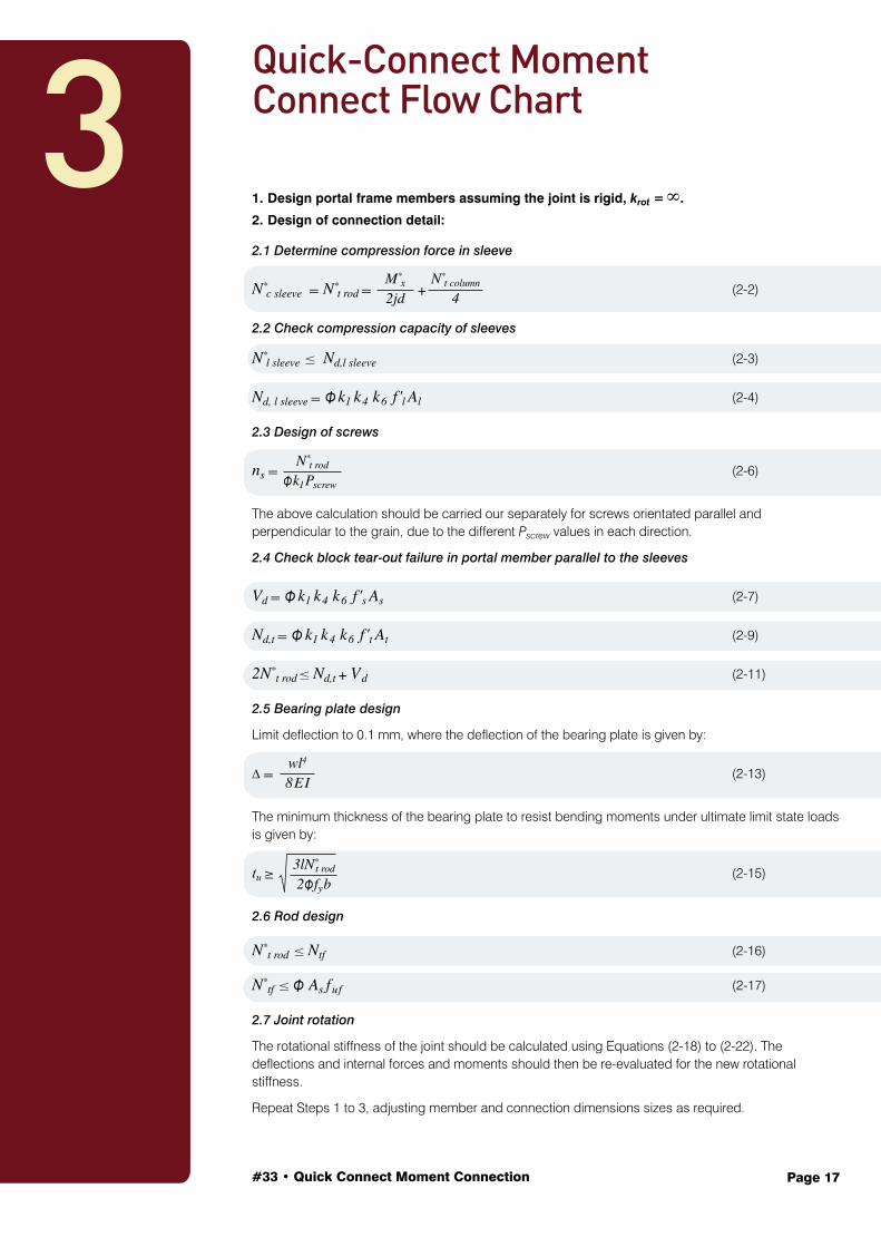
1. Design portal frame members assuming the joint is rigid, krot = ∞.
2. Design of connection detail:
2.1 Determine compression force in sleeve
N*c sleeve = N*
t rod = + (2-2)
2.2 Check compression capacity of sleeves
N*l sleeve ≤ Nd,l sleeve (2-3)
Nd, l sleeve = Φ k1 k4 k6 f 'l Al (2-4)
2.3 Design of screws
ns = (2-6)
The above calculation should be carried our separately for screws orientated parallel and perpendicular to the grain, due to the different Pscrew values in each direction.
2.4 Check block tear-out failure in portal member parallel to the sleeves
Vd = Φ k1 k4 k6 f 's As (2-7)
Nd,t = Φ k1 k4 k6 f 't At (2-9)
2N*t rod ≤ Nd,t + Vd (2-11)
2.5 Bearing plate design
Limit deflection to 0.1 mm, where the deflection of the bearing plate is given by:
∆ = (2-13)
The minimum thickness of the bearing plate to resist bending moments under ultimate limit state loads is given by:
tu ≥ (2-15)
2.6 Rod design
N*t rod ≤ Ntf (2-16)
N*tf ≤ Φ As fuf (2-17)
2.7 Joint rotation
The rotational stiffness of the joint should be calculated using Equations (2-18) to (2-22). The deflections and internal forces and moments should then be re-evaluated for the new rotational stiffness.
Repeat Steps 1 to 3, adjusting member and connection dimensions sizes as required.
3Quick-Connect Moment Connect Flow Chart
M*x
2jdN*
t column
4
N*t rod
Φk1Pscrew
wl4
8EI
3lN*t rod
2Φ fyb
#33 • Quick Connect Moment Connection Page 18
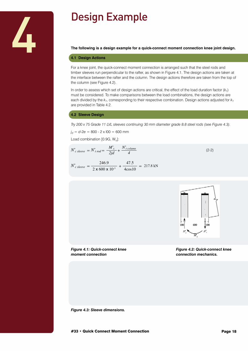
The following is a design example for a quick-connect moment connection knee joint design.
4.1 Design Actions
For a knee joint, the quick-connect moment connection is arranged such that the steel rods and timber sleeves run perpendicular to the rafter, as shown in Figure 4.1. The design actions are taken at the interface between the rafter and the column. The design actions therefore are taken from the top of the column (see Figure 4.2).
In order to assess which set of design actions are critical, the effect of the load duration factor (k1) must be considered. To make comparisons between the load combinations, the design actions are each divided by the k1, corresponding to their respective combination. Design actions adjusted for k1 are provided in Table 4.2.
4.2 Sleeve Design
Try 200 x 75 Grade 11 LVL sleeves continuing 30 mm diameter grade 8.8 steel rods (see Figure 4.3).
jd = d-2e = 800 - 2 x l00 = 600 mm
Load combination [0.9G, Wu]:
N*c sleeve = N*
t rod = + (2-2)
N*c sleeve = + = 217.8 kN
Figure 4.1: Quick-connect knee Figure 4.2: Quick-connect knee moment connection connection mechanics.
Figure 4.3: Sleeve dimensions.
4Design Example
M*x
2jd
246.92 x 600 x 10-3
47.54cos10
N*t column
4
#33 • Quick Connect Moment Connection Page 19
N*t rod
Φk1Pscrew
217.80.8 x 1.14 x 13.6
Note that for this configuration, the tension in the rod is resulting from shear in the rafter. The sleeves are sized for axial compression loads when the rods are in tension. Negative axial forces N*column are not considered as they do not affect N*t,rod.
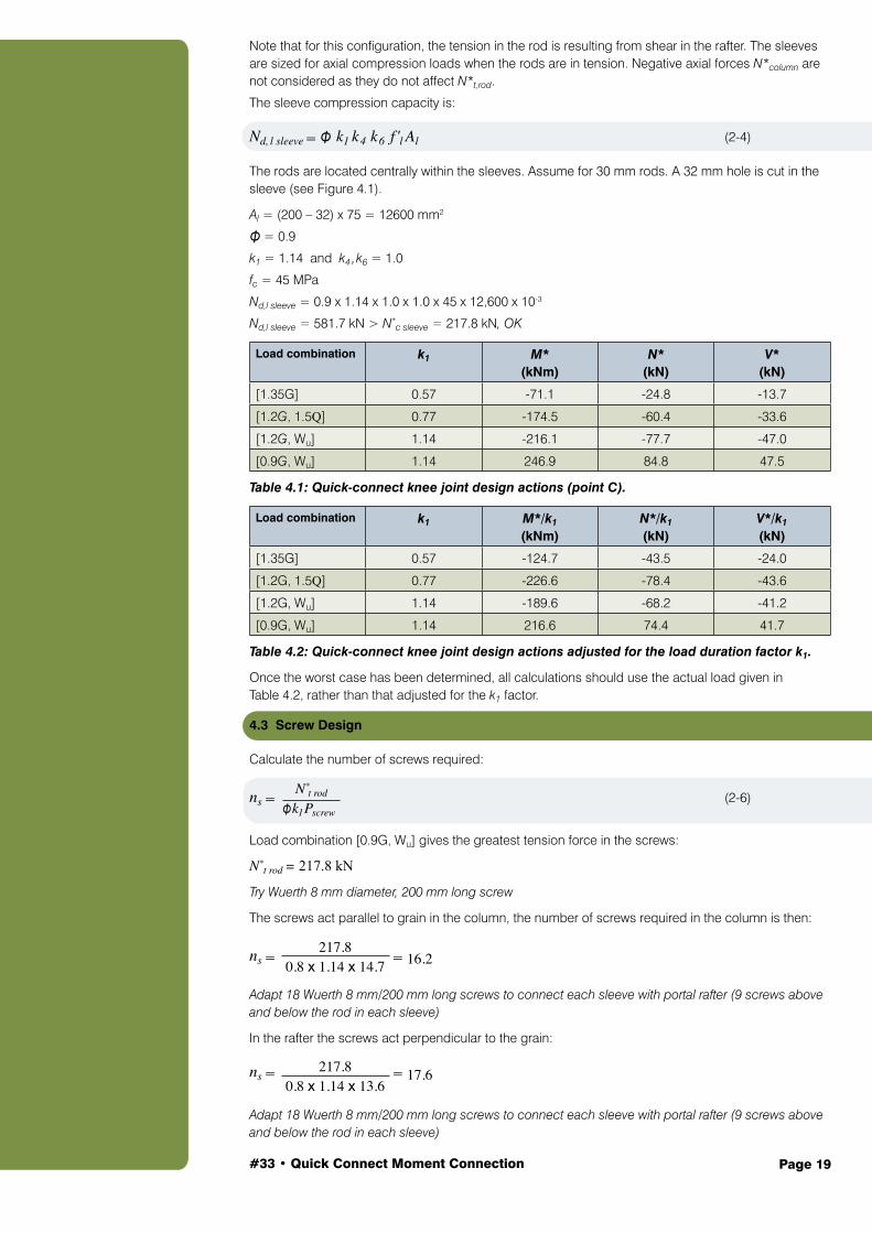
The sleeve compression capacity is:
Nd, l sleeve = Φ k1 k4 k6 f 'l Al (2-4)
The rods are located centrally within the sleeves. Assume for 30 mm rods. A 32 mm hole is cut in the sleeve (see Figure 4.1).
Al = (200 – 32) x 75 = 12600 mm2
Φ = 0.9
k1 = 1.14 and k4 ,k6 = 1.0
fc = 45 MPa
Nd,l sleeve = 0.9 x 1.14 x 1.0 x 1.0 x 45 x 12,600 x 10-3
Nd,l sleeve = 581.7 kN > N*c sleeve = 217.8 kN, OK
Load combination k1 M* (kNm)
N* (kN)
V* (kN)
[1.35G] 0.57 -71.1 -24.8 -13.7
[1.2G, 1.5Q] 0.77 -174.5 -60.4 -33.6
[1.2G, Wu] 1.14 -216.1 -77.7 -47.0
[0.9G, Wu] 1.14 246.9 84.8 47.5
Table 4.1: Quick-connect knee joint design actions (point C).
Load combination k1 M*/k1 (kNm)
N*/k1 (kN)
V*/k1 (kN)
[1.35G] 0.57 -124.7 -43.5 -24.0
[1.2G, 1.5Q] 0.77 -226.6 -78.4 -43.6
[1.2G, Wu] 1.14 -189.6 -68.2 -41.2
[0.9G, Wu] 1.14 216.6 74.4 41.7
Table 4.2: Quick-connect knee joint design actions adjusted for the load duration factor k1.
Once the worst case has been determined, all calculations should use the actual load given in Table 4.2, rather than that adjusted for the k1 factor.
4.3 Screw Design
Calculate the number of screws required:
ns = (2-6)
Load combination [0.9G, Wu] gives the greatest tension force in the screws:
N*t rod = 217.8 kN
Try Wuerth 8 mm diameter, 200 mm long screw
The screws act parallel to grain in the column, the number of screws required in the column is then:
ns = = 16.2
Adapt 18 Wuerth 8 mm/200 mm long screws to connect each sleeve with portal rafter (9 screws above and below the rod in each sleeve)
In the rafter the screws act perpendicular to the grain:
ns = = 17.6
Adapt 18 Wuerth 8 mm/200 mm long screws to connect each sleeve with portal rafter (9 screws above and below the rod in each sleeve)
217.80.8 x 1.14 x 14.7
#33 • Quick Connect Moment Connection Page 20
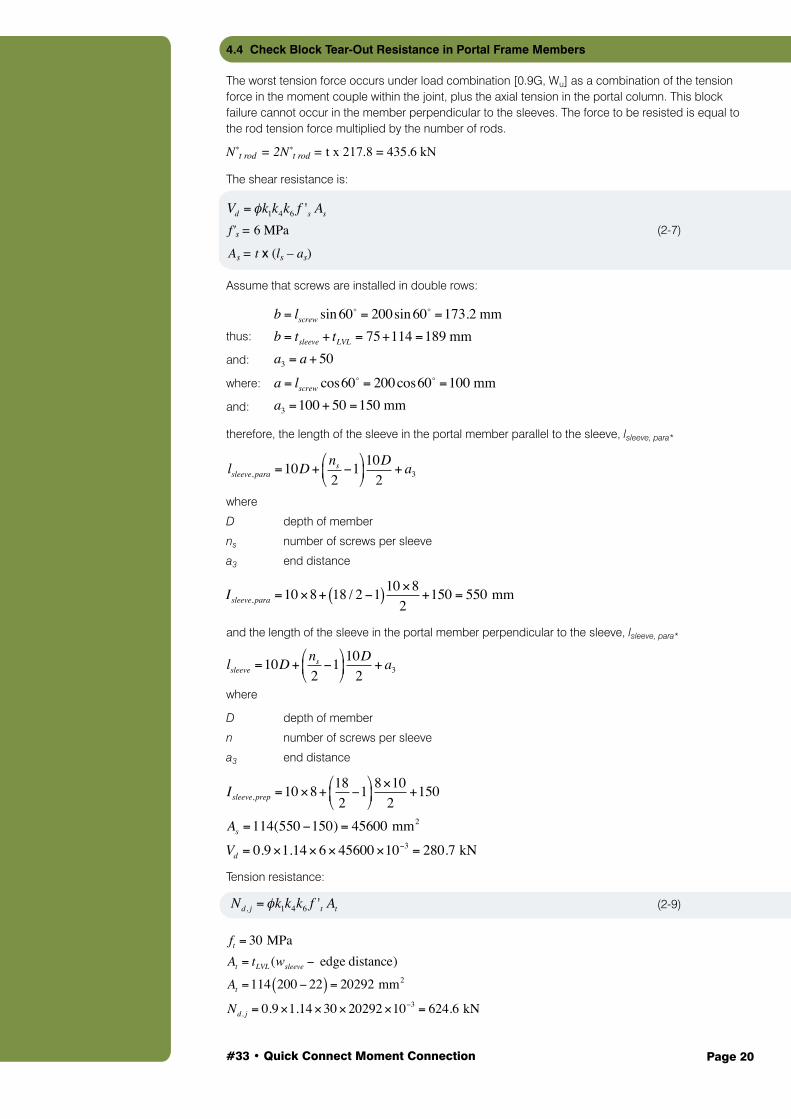
4.4 Check Block Tear-Out Resistance in Portal Frame Members
The worst tension force occurs under load combination [0.9G, Wu] as a combination of the tension force in the moment couple within the joint, plus the axial tension in the portal column. This block failure cannot occur in the member perpendicular to the sleeves. The force to be resisted is equal to the rod tension force multiplied by the number of rods.
N*t rod = 2N*
t rod = t x 217.8 = 435.6 kN
The shear resistance is:
(2-7)
Assume that screws are installed in double rows:
thus:
and:
where:
and:
therefore, the length of the sleeve in the portal member parallel to the sleeve, lsleeve, para*
where
D depth of member
ns number of screws per sleeve
a3 end distance
lsleeve,para =10D+ns
2−1
⎛
⎝⎜
⎞
⎠⎟10D
2+ a3
Vd = φk1k4k6 f 's As
f 's = 6MPa
As = t •(ls − as )
and the length of the sleeve in the portal member perpendicular to the sleeve, lsleeve, para*
where
D depth of member
n number of screws per sleeve
a3 end distance
Tension resistance:
(2-9) Nd, j = φk1k4k6 f 't At
lsleeve =10D+ns
2−1
⎛
⎝⎜
⎞
⎠⎟10D
2+ a3
As = t x (ls – as)
f's = 6 MPa
Isleeve,para =10×8+ 18 / 2−1( )10×82
+150 = 550 mm
b = lscrew sin60 = 200sin60 =173.2 mm
b = tsleeve + tLVL = 75+114 =189 mma3 = a+ 50a = lscrew cos60
= 200cos60 =100 mma3 =100+ 50 =150 mm
Isleeve,prep =10×8+ 182−1
⎛
⎝⎜
⎞
⎠⎟8×10
2+150
As =114(550−150) = 45600 mm2
Vd = 0.9×1.14×6× 45600×10−3 = 280.7 kN
ft = 30 MPaAt = tLVL (wsleeve − edge distance)At =114 200− 22( ) = 20292 mm2
Nd, j = 0.9×1.14×30×20292×10−3 = 624.6 kN
#33 • Quick Connect Moment Connection Page 21
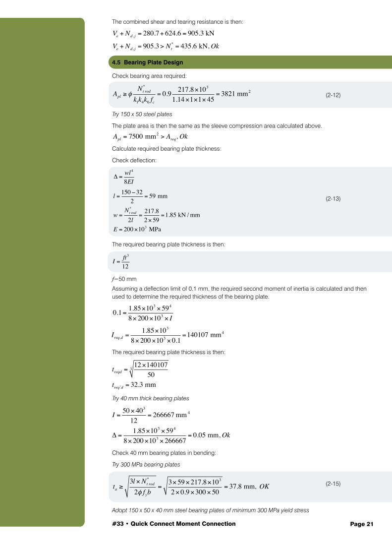
The combined shear and tearing resistance is then:
4.5 Bearing Plate Design
Check bearing area required:
(2-12)
Try 150 x 50 steel plates
The plate area is then the same as the sleeve compression area calculated above.
Calculate required bearing plate thickness:
Check deflection:
(2-13)
The required bearing plate thickness is then:
(2-14)
f=50 mm
Assuming a deflection limit of 0.1 mm, the required second moment of inertia is calculated and then used to determine the required thickness of the bearing plate.
The required bearing plate thickness is then:
Try 40 mm thick bearing plates
Check 40 mm bearing plates in bending:
Try 300 MPa bearing plates
(2-15)
Adopt 150 x 50 x 40 mm steel bearing plates of minimum 300 MPa yield stress
Δ =wl4
8EI
I =ft3
12
0.1= 1.85×103 ×594
8×200×103 × I
Ireqd =1.85×10³
8×200×103 ×0.1=140107mm4
Apl ≥ φNt rod
*
k1k4k6 fc
= 0.9 217.8×10³
1.14×1×1× 45= 3821 mm2
Ve + Nd, j = 280.7+ 624.6 = 905.3 kN
Ve + Nd, j = 905.3> Nt* = 435.6 kN, Ok
Apl = 7500 mm2 > Areq, Ok
l =150−32
2= 59 mm
w =Nt rod
*
2l=
217.82×59
=1.85 kN / mm
E = 200×103 MPa
Ireq,d =1.85×10³
8×200×103 ×0.1=140107 mm4
treqd =12×140107
503
treq’d = 32.3 mm
I =50× 403
12= 266667 mm 4
Δ =1.85×103 ×594
8×200×103 ×266667= 0.05 mm, Ok
ta ≥3l ×Nt rod
*
2φ fyb=
3×59×217.8×103
2×0.9×300×50= 37.8 mm, OK
#33 • Quick Connect Moment Connection Page 22
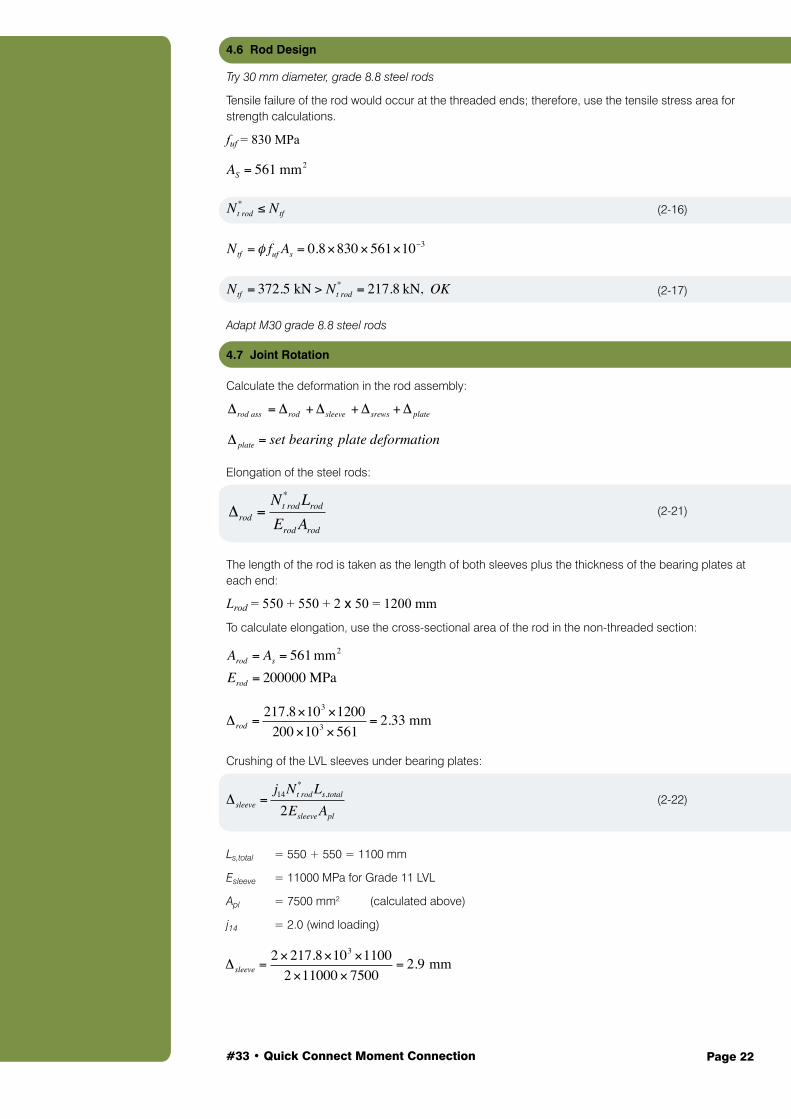
4.6 Rod Design
Try 30 mm diameter, grade 8.8 steel rods
Tensile failure of the rod would occur at the threaded ends; therefore, use the tensile stress area for strength calculations.
fuf = 830 MPa
(2-16)
(2-17)
Adapt M30 grade 8.8 steel rods
4.7 Joint Rotation
Calculate the deformation in the rod assembly:
Elongation of the steel rods:
(2-21)
The length of the rod is taken as the length of both sleeves plus the thickness of the bearing plates at each end:
Lrod = 550 + 550 + 2 x 50 = 1200 mm
To calculate elongation, use the cross-sectional area of the rod in the non-threaded section:
Crushing of the LVL sleeves under bearing plates:
(2-22)
Ls,total = 550 + 550 = 1100 mm
Esleeve = 11000 MPa for Grade 11 LVL
Apl = 7500 mm2 (calculated above)
j14 = 2.0 (wind loading)
Δrod =Nt rod* Lrod
Erod Arod
Δsleeve =j14Nt rod
* Ls,total
2Esleeve Apl
AS = 561 mm2
Nt rod* ≤ Ntf
Ntf = φ fuf As = 0.8×830×561×10−3
Ntf = 372.5 kN > Nt rod* = 217.8 kN, OK
Δrod ass = Δrod +Δsleeve +Δsrews +Δ plate
Δ plate = set bearing plate deformation
Arod = As = 561mm2
Erod = 200000 MPa
Δrod =217.8×103 ×1200
200×103 ×561= 2.33 mm
Δsleeve =2×217.8×103 ×1100
2×11000× 7500= 2.9 mm
#33 • Quick Connect Moment Connection Page 23
Δrod ass = 2.33+ 2.9+1.41+ 0.05= 6.69 mm
θ =Δrod ass
jd
θ =6.69600
=11.2×10⁻³ radians
krot =M *θ
krot =246.9×10³
11.2×10−3= 22×106Nm / radians
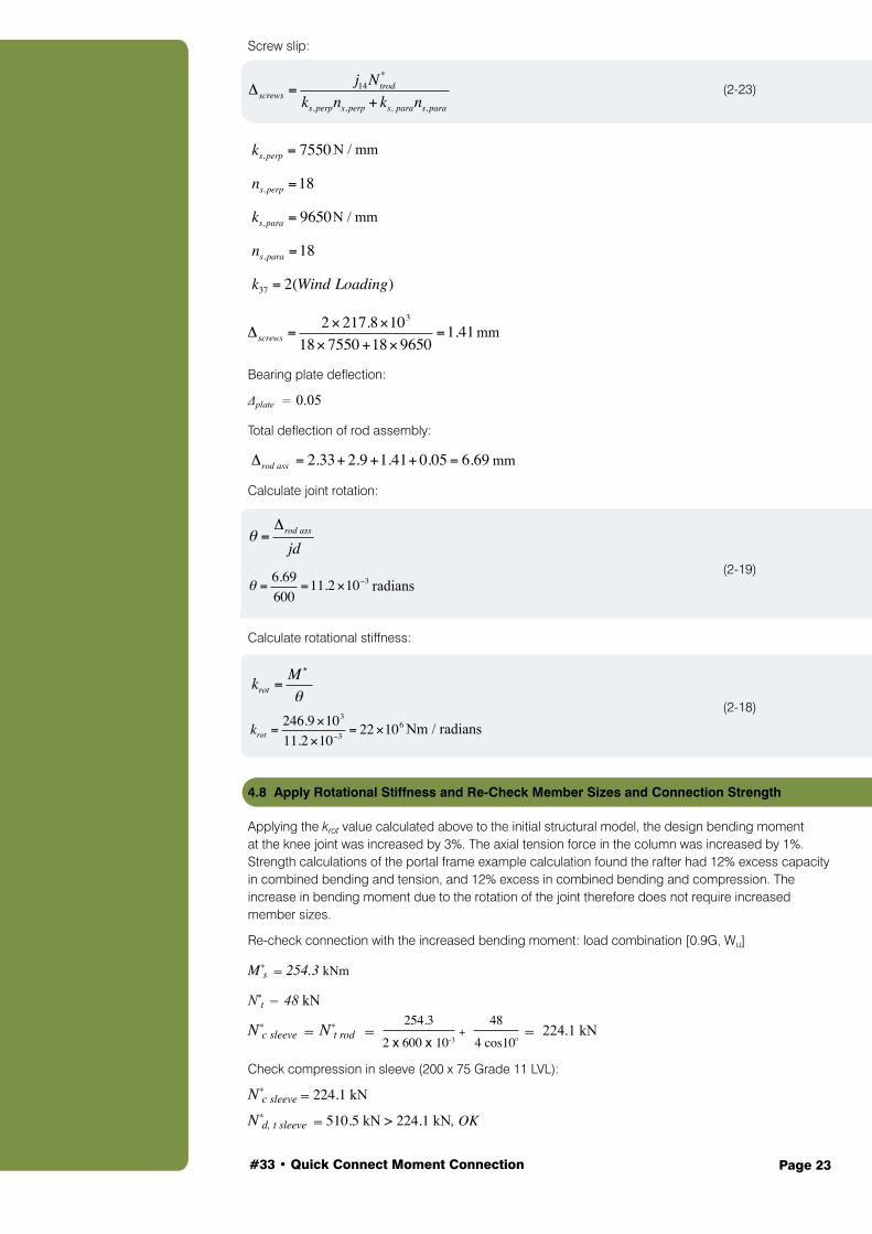
Screw slip:
(2-23)
Bearing plate deflection:
Δplate = 0.05
Total deflection of rod assembly:
Calculate joint rotation:
(2-19)
Calculate rotational stiffness:
(2-18)
4.8 Apply Rotational Stiffness and Re-Check Member Sizes and Connection Strength
Applying the krot value calculated above to the initial structural model, the design bending moment at the knee joint was increased by 3%. The axial tension force in the column was increased by 1%. Strength calculations of the portal frame example calculation found the rafter had 12% excess capacity in combined bending and tension, and 12% excess in combined bending and compression. The increase in bending moment due to the rotation of the joint therefore does not require increased member sizes.
Re-check connection with the increased bending moment: load combination [0.9G, Wu]
M*s = 254.3 kNm
N*t = 48 kN
N*c sleeve = N*
t rod = + = 224.1 kN
Check compression in sleeve (200 x 75 Grade 11 LVL):
N*c sleeve = 224.1 kN
N*d, t sleeve = 510.5 kN > 224.1 kN, OK
Δscrews =j14Ntrod
*
ks,perpns,perp + ks, parans,para
ks,perp = 7550N /mm
ns,perp =18
ks,para = 9650N /mm
ns,para =18
k37 = 2(Wind Loading)
Δscrews =2×217.8×103
18× 7550+18×9650=1.41mm
254.3
2 x 600 x 10-3
48
4 cos100
N / mm
N / mm
mm
Nm / radians
radians
mm
*
#33 • Quick Connect Moment Connection Page 24
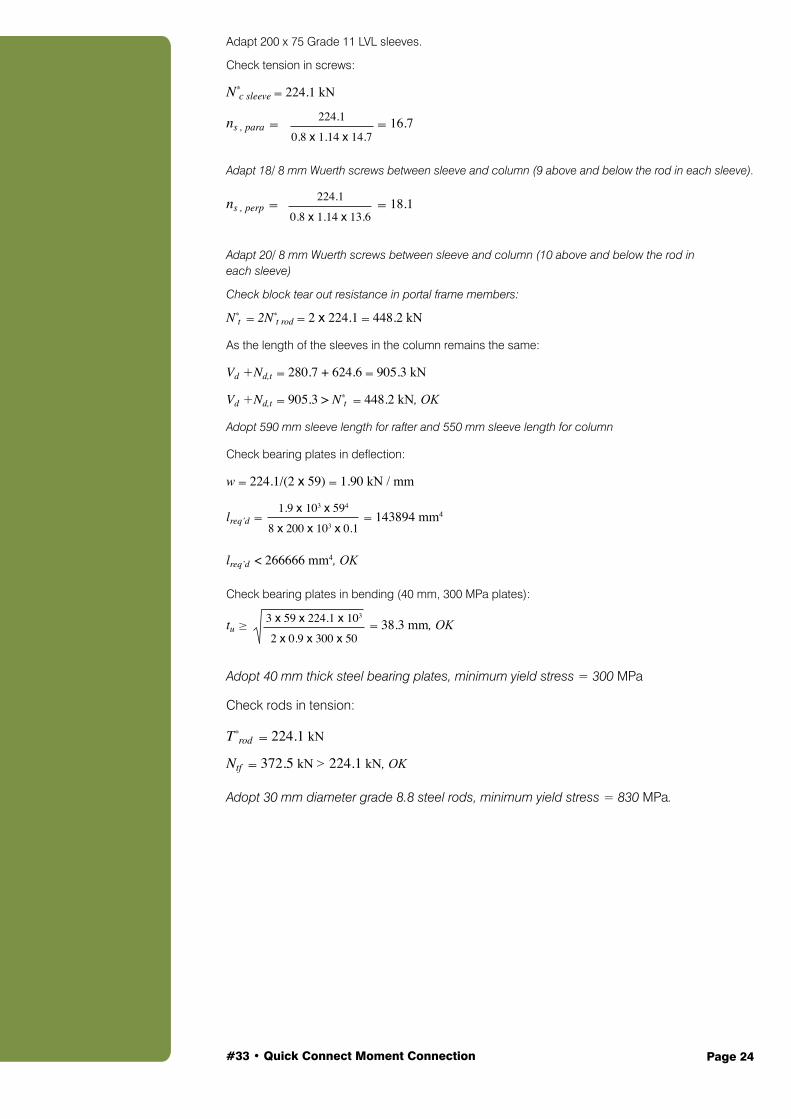
Adapt 200 x 75 Grade 11 LVL sleeves.
Check tension in screws:
N*c sleeve = 224.1 kN
ns , para = = 16.7
Adapt 18/ 8 mm Wuerth screws between sleeve and column (9 above and below the rod in each sleeve).
ns , perp = = 18.1
Adapt 20/ 8 mm Wuerth screws between sleeve and column (10 above and below the rod in each sleeve)
Check block tear out resistance in portal frame members:
N*t = 2N*
t rod = 2 x 224.1 = 448.2 kN
As the length of the sleeves in the column remains the same:
Vd +Nd,t = 280.7 + 624.6 = 905.3 kN
Vd +Nd,t = 905.3 > N*t = 448.2 kN, OK
Adopt 590 mm sleeve length for rafter and 550 mm sleeve length for column
Check bearing plates in deflection:
w = 224.1/(2 x 59) = 1.90 kN / mm
lreq’d = = 143894 mm4
lreq’d < 266666 mm4, OK
Check bearing plates in bending (40 mm, 300 MPa plates):
tu ≥ = 38.3 mm, OK
Adopt 40 mm thick steel bearing plates, minimum yield stress = 300 MPa
Check rods in tension:
T*rod = 224.1 kN
Ntf = 372.5 kN > 224.1 kN, OK
Adopt 30 mm diameter grade 8.8 steel rods, minimum yield stress = 830 MPa.
224.1
0.8 x 1.14 x 14.7
224.1
0.8 x 1.14 x 13.6
3 x 59 x 224.1 x 103
2 x 0.9 x 300 x 50
1.9 x 103 x 594
8 x 200 x 103 x 0.1
#33 • Quick Connect Moment Connection Page 25
1. Milner, H.R. and D. Crozier, Structural Design of Timber Portal Frame Buildings. 2000: Engineers Australia.
2. Batchelar, M. and K. Mcintosh. Structural joints in glulam. in Proceedings of the 5th World conference in Timber Engineering, Montreux. 1998.
3. Scheibmair, F. and P. Quenneville, Moment Connection for Quick Assembly of Timber Portal Frame Buildings: Theory and Validation. Journal of Structural Engineering, 2014. 140(1): p. 04013022.
4. Blass, H.J. and I. Bejtka, Screws with continuous threads in timber connections. Joints in Timber Structures: Stuttgart, Germany, 12-14 September 2001, 2001: p. 193.
5. Dhillon, B. and J. O'Malley Interactive Design of Semirigid Steel Frames. Journal of Structural Engineering, 1999. 125(5): p. 556-564.
Australian Standards
AS 1720.1, Timber structures, in Part 1: Design methods. 2010, Standards Australia: Australia.
References

#33 • Quick Connect Moment Connection Page 26
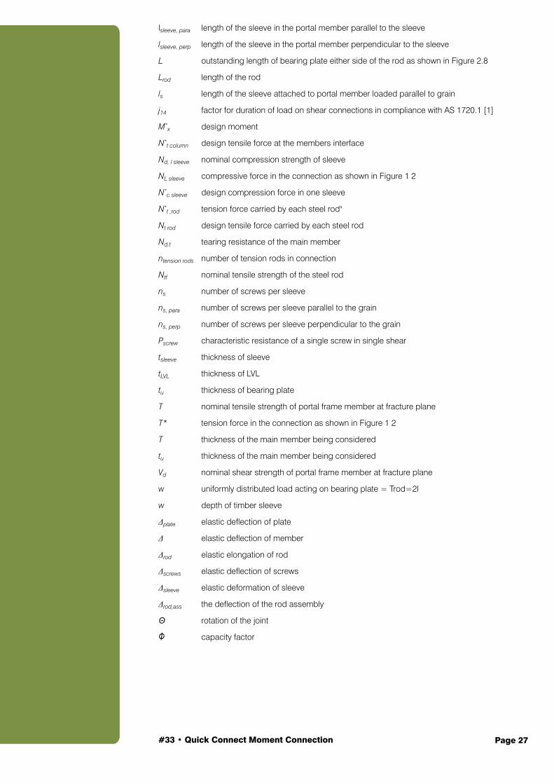
The symbols and letters used in the Guide are listed below:
Al net cross-sectional area of sleeve acting in compression
Apl bearing plate area
Arod area of steel rod
As shear plane area of fracture plane in timber member
At tensile plane area of fracture plane in timber member
a3 end distance, as shown in Figure 2 3
a4 edge distance, as shown in Figure 2 3
B breadth of member as shown in Figure 2 3
bp breadth of bearing plate as shown in Figure 2 8
D depth of member (in direction of flexural loading) as shown in Figure 1 2
da diameter of screw
dp depth of bearing plate as shown in Figure 2 8
ds depth of sleeve as shown in Figure 2 3
Esleeve modulus of elasticity of timber sleeve
Etimber modulus of elasticity of timber member
Erod modulus of elasticity of rod
E modulus of elasticity of member
E distance from the extreme fibre to the centre of the rod as shown in Figure 1 2
f’c characteristic strength in compression parallel to the grain of timber
f’l characteristic compression stress timber of sleeves
f’s characteristic shear strength of timber
f’t characteristic strength in tension parallel to the grain of timber
fuf specified minimum tensile strength of steel rod
fy yield strength of steel
I moment of inertia
jd moment arm between the steel rods, as shown in Figure 1 2
krot rotational stiffness of the joint as shown in Figure 2 1
ks screw connection stiffness factor
k1 duration of load (timber)
k4 moisture condition (timber)
k6 temperature (timber)
k12 stability factor (timber)
ks, perp screw connection stiffness factor perpendicular to the grain
ks, para screw connection stiffness factor parallel to the grain
Ls, total total sleeve length. For a timber to timber connection, add the sleeve length on both sides of the connection
AAppendix A - Notations
#33 • Quick Connect Moment Connection Page 27
lsleeve, para length of the sleeve in the portal member parallel to the sleeve
lsleeve, perp length of the sleeve in the portal member perpendicular to the sleeve
L outstanding length of bearing plate either side of the rod as shown in Figure 2.8
Lrod length of the rod
ls length of the sleeve attached to portal member loaded parallel to grain
j14 factor for duration of load on shear connections in compliance with AS 1720.1 [1]
M*x design moment
N*t column design tensile force at the members interface
Nd, l sleeve nominal compression strength of sleeve
NL sleeve compressive force in the connection as shown in Figure 1 2
N*c sleeve design compression force in one sleeve
N*t ,rod tension force carried by each steel rod"
Nt rod design tensile force carried by each steel rod
Nd,t tearing resistance of the main member
ntension rods number of tension rods in connection
Ntf nominal tensile strength of the steel rod
ns number of screws per sleeve
ns, para number of screws per sleeve parallel to the grain
ns, perp number of screws per sleeve perpendicular to the grain
Pscrew characteristic resistance of a single screw in single shear
tsleeve thickness of sleeve
tLVL thickness of LVL
tu thickness of bearing plate
T nominal tensile strength of portal frame member at fracture plane
T* tension force in the connection as shown in Figure 1 2
T thickness of the main member being considered
tu thickness of the main member being considered
Vd nominal shear strength of portal frame member at fracture plane
w uniformly distributed load acting on bearing plate = Trod=2l
w depth of timber sleeve
Δplate elastic deflection of plate
Δ elastic deflection of member
Δrod elastic elongation of rod
Δscrews elastic deflection of screws
Δsleeve elastic deformation of sleeve
Δrod,ass the deflection of the rod assembly
Θ rotation of the joint
Φ capacity factor

Discover more ways to build your knowledge of wood If you need technical information or inspiration on designing and building with wood, you’ll find WoodSolutions has the answers. From technical design and engineering advice to inspiring projects and CPD linked activities, WoodSolutions has a wide range of resources and professional seminars.
www.woodsolutions.com.auYour central resource for news about all WoodSolutions activities and access to more than three thousand pages of online information and downloadable publications.
Technical PublicationsA suite of informative, technical and training guides and handbooks that support the use of wood in residential and commercial buildings.
WoodSolutions TutorialsA range of practical and inspirational topics to educate and inform design and construction professionals. These free, CPD related, presentations can be delivered at your workplace at a time that suits you.
Seminars and EventsFrom one day seminars featuring presentations from leading international and Australian speakers to international tours of landmark wood projects, WoodSolutions offer a range of professional development activities.
What is WoodSolutions?Developed by the Australian forest and wood products industry for design and building professionals, WoodSolutions is a non-proprietary source of information from industry bodies, manufacturers and suppliers.