Embed Size (px)
Citation preview
www.egger.com/osbrace
os’braceThe environmenTally susTainable bracing panel
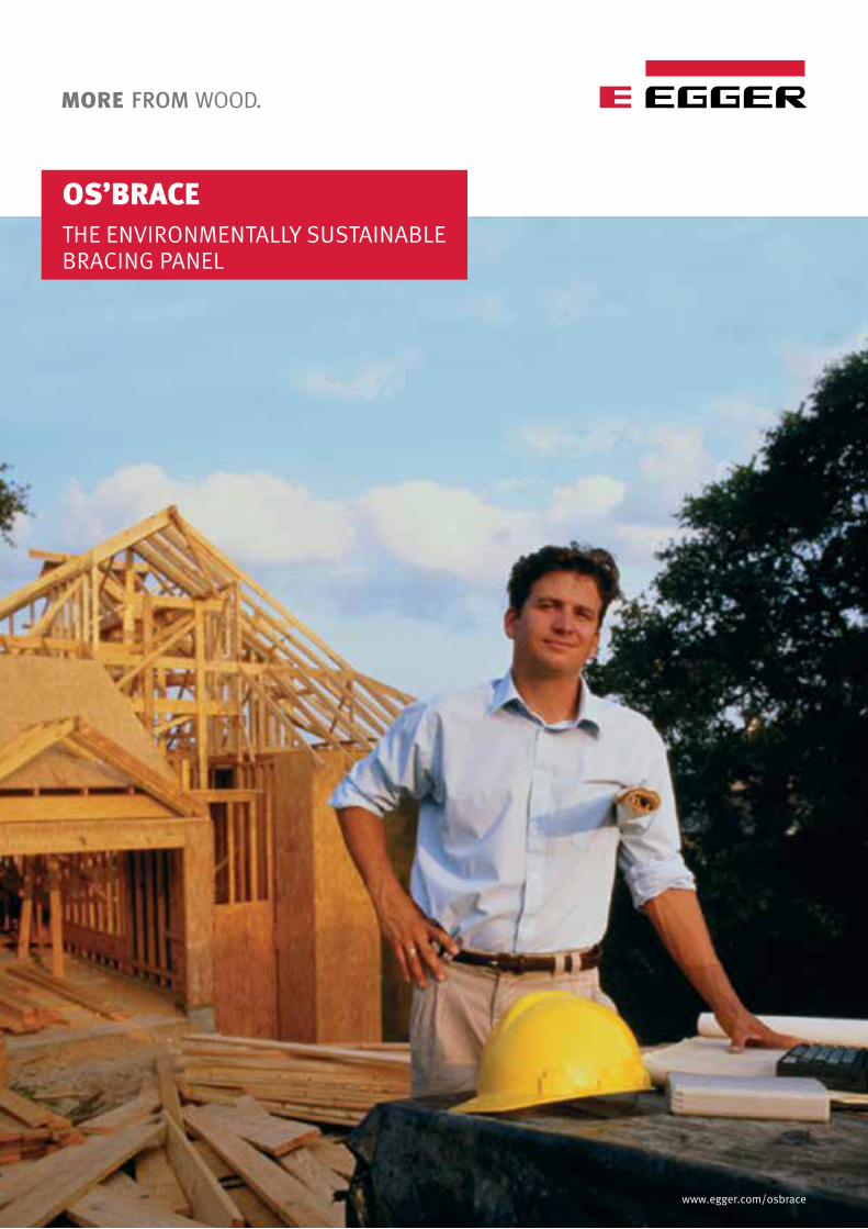
Architects, carpenters and home owners appreciate the beauty, flexibility and advantages of using wood as a building material. Designed to perform OS’Brace made by EGGER fulfills these expectations.
THe eNVIroNMeNTaLLY sUsTaINabLe bracING PaNeL WHAT IS OS’Brace?
os’brace is a high quality, moisture resistant, innovative and environmentally sustainable, structural bracing panel designed and manufactured specifically for the australian building and construction industry.
WHAT IS OS’Brace H2 Blue?
os’brace h2 blue is a termite-treated os’brace panel to h2 level complementing your fully termite-treated timber framing package. The h2 blue treatment is effective against termite species throughout australia (north and south of the Tropic of capricorn).
os’brace is a three-layered, flat-pressed egger eurosTranD osb panel of oriented strands (micro-veneers) bonded with synthetic resin in accordance with en 300:2006 osb. The panel is principally made of debarked round wood from sustainable managed forests. separate strand processing for the core and surface layers, special strand geometry and a high level of orientation of the surface strands in the direction of the fibre optimises os’brace’s structural performance and physical appearance.
MaDe IN eUroPe
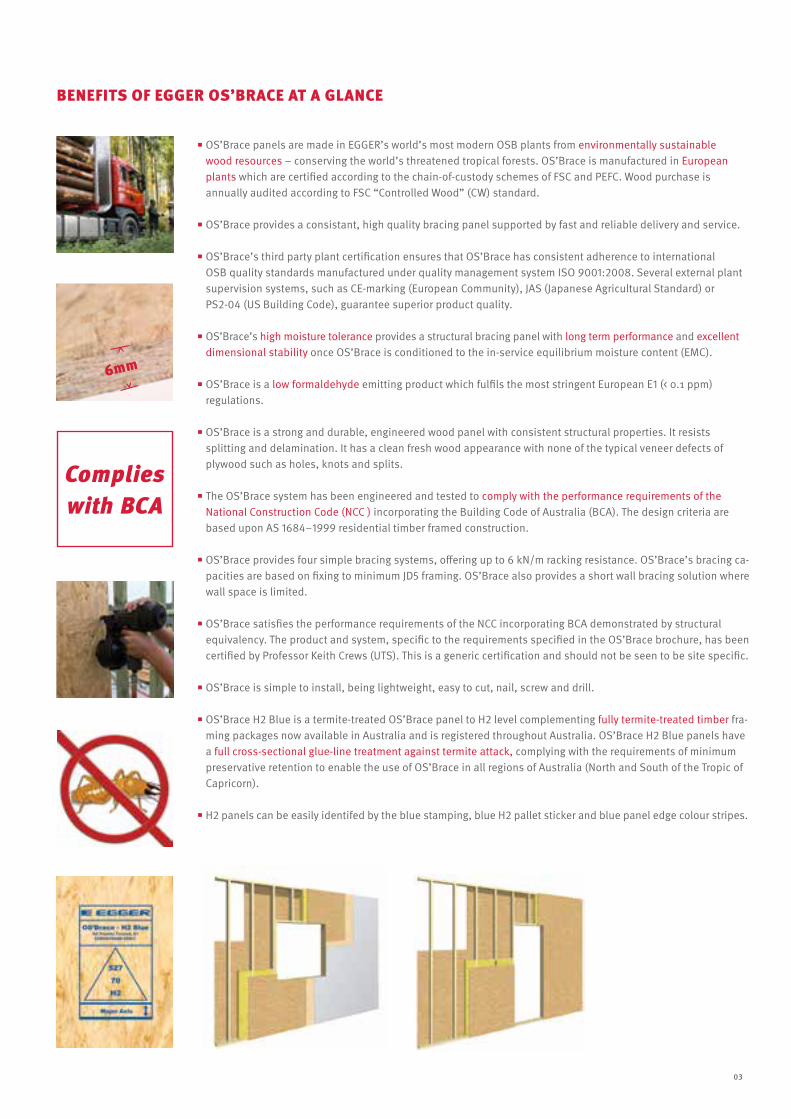
os’brace panels are made in egger’s world’s most modern osb plants from environmentally sustainable wood resources − conserving the world’s threatened tropical forests. os’brace is manufactured in european plants which are certified according to the chain-of-custody schemes of Fsc and peFc. Wood purchase is annually audited according to Fsc “controlled Wood” (cW) standard.
os’brace provides a consistant, high quality bracing panel supported by fast and reliable delivery and service.
os’brace’s third party plant certification ensures that os’brace has consistent adherence to international osb quality standards manufactured under quality management system iso 9001:2008. several external plant supervision systems, such as ce-marking (european community), Jas (Japanese agricultural standard) or ps2-04 (us building code), guarantee superior product quality.
os’brace’s high moisture tolerance provides a structural bracing panel with long term performance and excellent dimensional stability once os’brace is conditioned to the in-service equilibrium moisture content (emc).
os’brace is a low formaldehyde emitting product which fulfils the most stringent european e1 (< 0.1 ppm) regulations.
os’brace is a strong and durable, engineered wood panel with consistent structural properties. it resists splitting and delamination. it has a clean fresh wood appearance with none of the typical veneer defects of plywood such as holes, knots and splits.
The os’brace system has been engineered and tested to comply with the performance requirements of the national construction code (ncc ) incorporating the building code of australia (bca). The design criteria are based upon as 1684–1999 residential timber framed construction.
os’brace provides four simple bracing systems, offering up to 6 kn/m racking resistance. os’brace’s bracing ca-pacities are based on fixing to minimum JD5 framing. os’brace also provides a short wall bracing solution where wall space is limited.
os’brace satisfies the performance requirements of the ncc incorporating bca demonstrated by structural equivalency. The product and system, specific to the requirements specified in the os’brace brochure, has been certified by professor Keith crews (uTs). This is a generic certification and should not be seen to be site specific. os’brace is simple to install, being lightweight, easy to cut, nail, screw and drill.
os’brace h2 blue is a termite-treated os’brace panel to h2 level complementing fully termite-treated timber fra-ming packages now available in australia and is registered throughout australia. os’brace h2 blue panels have a full cross-sectional glue-line treatment against termite attack, complying with the requirements of minimum preservative retention to enable the use of os’brace in all regions of australia (north and south of the Tropic of capricorn).
h2 panels can be easily identifed by the blue stamping, blue h2 pallet sticker and blue panel edge colour stripes.
6mm
Complies with BCA
beNeFITs oF eGGer os’brace aT a GLaNce
03
InSTAllATIOnos’brace should be installed in accordance with standard building design and construction methods. prolonged exposure to moisture and excessive condensation must not occur.
os’brace is suitable for use in humid conditions where the panel in-service moisture content does not exceed 20 %. This is defined in en 13986:2004 as service class 2. This service class is appropriate for the installation of os’brace within the cavity of a brick veneer building or under cladding throughout australia. as is the case with all wood-based products, os’brace is hygro-scopic, meaning that the panel’s final resting moisture content will adjust to the equilibrium moisture content (emc) of the site. correct installation procedure must be observed to allow for the small dimensional movement in the os’brace panel in response to changes in emc.
os’brace should be allowed to acclimatise (pick up moisture) for at least a 48 hour period prior to installation.
Do noT butt joint os’brace panels tightly. To allow for hygro-scopic movement, a minimum 2 mm expansion gap must be allowed around the full perimeter of the panel and at any butt joint between os’brace panels.
os’brace sYsTeM DesIGN aND INsTaLLaTIoN
HOlES THROuGH OS’BRAcE BRAcInG as os’brace possesses similar shear carrying capacity to other sheet bracing materials, allowable holes through os’brace in size and distribution would be similar to these materials.
a hole 100 × 100 mm maximum within an envelope of 100 mm from top and vertical edges and 200 mm of the bottom of the bracing panel will not signifcantly affect the bracing capacity. multiple holes of this size are permitted provided the centre lines of the holes are not closer than 600 mm.
SAWInG, DRIllInG, SHApInG
os’brace can be sawn and shaped in the same way as solid wood with standard stationary tools and (electrical) hand-held tools. carbide tipped cutters are recommended. if panels are to be installed in a visible location, ensure clean-cut edges with sharp tools.
The feed rate should be somewhat slower than for solid wood.if hand-held equipment without suction removal is used, a protective face mask should be worn. os’brace may be drilled with all electrical and hand-held tools suitable for solid wood.
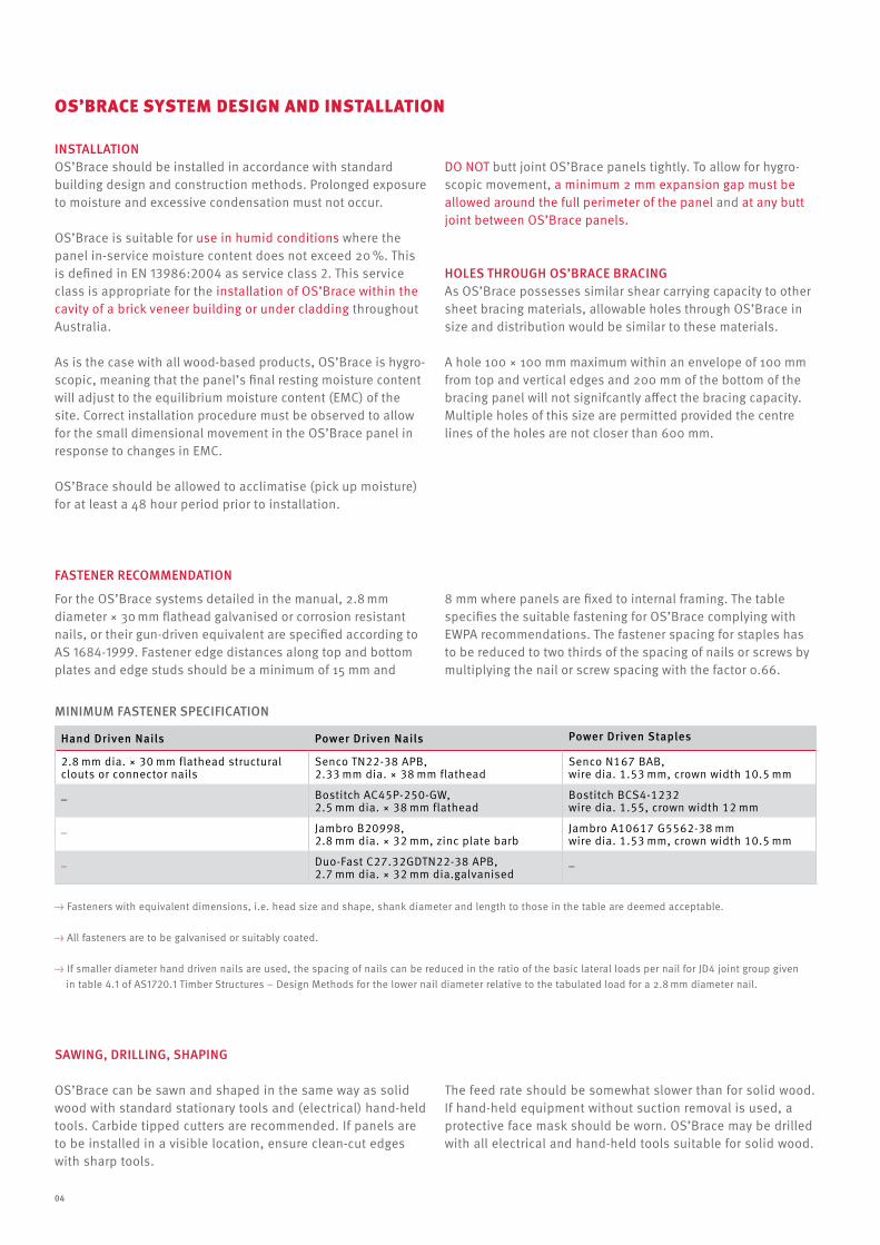
FASTEnER REcOMMEnDATIOn
For the os’brace systems detailed in the manual, 2.8 mm diameter × 30 mm flathead galvanised or corrosion resistant nails, or their gun-driven equivalent are specified according to as 1684-1999. Fastener edge distances along top and bottom plates and edge studs should be a minimum of 15 mm and
8 mm where panels are fixed to internal framing. The table specifies the suitable fastening for os’brace complying with eWpa recommendations. The fastener spacing for staples has to be reduced to two thirds of the spacing of nails or screws by multiplying the nail or screw spacing with the factor 0.66.
Hand Driven nails power Driven nails power Driven Staples
2.8 mm dia. × 30 mm flathead structural clouts or connector nails
senco Tn22-38 apb, 2.33 mm dia. × 38 mm flathead
senco n167 bab, wire dia. 1.53 mm, crown width 10.5 mm
_ bostitch ac45p-250-gW, 2.5 mm dia. × 38 mm flathead
bostitch bcs4-1232wire dia. 1.55, crown width 12 mm
_ Jambro b20998, 2.8 mm dia. × 32 mm, zinc plate barb
Jambro a10617 g5562-38 mmwire dia. 1.53 mm, crown width 10.5 mm
_ Duo-Fast c27.32gDTn22-38 apb,2.7 mm dia. × 32 mm dia.galvanised
_
→ Fasteners with equivalent dimensions, i.e. head size and shape, shank diameter and length to those in the table are deemed acceptable.
→ all fasteners are to be galvanised or suitably coated.
→ if smaller diameter hand driven nails are used, the spacing of nails can be reduced in the ratio of the basic lateral loads per nail for JD4 joint group given in table 4.1 of as1720.1 Timber structures – Design methods for the lower nail diameter relative to the tabulated load for a 2.8 mm diameter nail.
MInIMuM FASTEnER SpEcIFIcATIOn
04
OS’BRAcE BRAcInG cApAcITY The racking resistance values for os’brace have been derived from independent testing of full scale prototype panels at the Faculty of engineering and physical systems, central Queens-land university. The testing methods used have been developed over three decades by the cQu and have been calibrated to over 30 years of actual performance in buildings around australia subjected to real wind forces. Therefore the os’brace racking values published in the manual can be used with great confi-dence and have been independently certifed by the university of Technology sydney as complying with the requirements of the building code of australia. bracing capacities for os’brace systems are given in the diagrams on the next pages for various fixing methods applicable for wall heights of up to 2.7 m. For wall heights exceeding 2.7 m, bracing resistances detailed must be reduced proportionally, e.g. for a wall height of 3.3 m, racking resistance reduction factor 2.7/3.3 = 0.82. minimum section (length of bracing) for system types 1, 2 and 3 is 900 mm. AncHORInG BOTTOM plATES anchoring of bottom plates shall be in accordance with as 1684-1999 or designed in accordance with as 1720.1-1997. hold down provided in the os’brace bracing system provides bracing resis-tance. additional fixings (cyclone rods) may be required to resist uplift forces and must be appropriately designed and installed.
BRIck TIES
When used in the cavity of a brick veneer, brick wall ties must be of the face-fixed type complying with as 2699. The ties should be nailed through the os’brace to the face of the stud. DESIGn ScOpE Where the building design or design wind speed parameters are outside the scope of as 1684-1999, a professional engineer should be consulted to determine the wind forces generated from as 4055-1992 or directly from as 1170.2-1989. TIMBER FRAMInG os’brace racking resistances detailed in the manual were gene-rated using framing timbers with nail holding resistance of JD5 and a maximum stud spacing of 600 mm centres. Therefore, no reduction factors are applicable for fixing to JD5, unlike plywood which requires a 12.5 % reduction factor, and hardboard, a 16 % reduction factor, when material reduces in joint strength group from JD4 to JD5. Where timber framing is of joint strength group JD4, independent testing has confirmed that the racking resis-tances given in this literature for os’brace system types 1, 2, 3 and 4 can be increased by a maximum of 10 %.
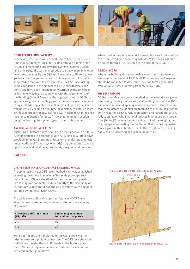
uplIFT RESISTAncE OF OS’BRAcE SHEATHED WAllSThe uplift resistance of os’brace sheathed walls was established by testing the failure in tension of full scale prototype sec-tions of the os’brace sheathed, timber-framed wall panels. The testing was conducted independently at the university of Technology sydney (uTs) and the design values were engineer-certified by professor Keith crews.
The table shows allowable uplift resistances of os’brace sheathed wall systems with minimum rafter or truss spacing of 900 mm.
Allowable uplift resistance [kn/rafter]
Fastener spacing (mm) top and bottom plates
7.5 80
8.5 40
Top plate to rafter or truss connection as per AS 1684
min. 900 mm
Tension
Bottom plate to floor or sub floor connection as per AS 1684
05
Wind uplift loads are transferred to the wall panels via the rafter or truss to top plate connection. The os’brace sheathed wall frames transfer these uplift loads to the bottom plates, the os’brace acting in tension as a continuous cycle rod as depicted in the figure above.
05
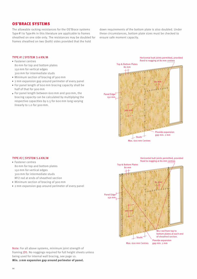
TYpE #1 | SYSTEM 3.4 kn/M Fastener centres
80 mm for top and bottom plates 150 mm for vertical edges 300 mm for intermediate studs minimum section of bracing of 900 mm 2 mm expansion gap around perimeter of every panel For panel length of 600 mm bracing capacity shall be
half of that for 900 mm For panel length between 600 mm and 900 mm, the
bracing capacity can be calculated by multiplying the respective capacities by 0.5 for 600 mm long varying linearly to 1.0 for 900 mm.
TYpE #2 | SYSTEM 5.6 kn/M Fastener centres
80 mm for top and bottom plates 150 mm for vertical edges 300 mm for intermediate studs m12 rod at ends of sheathed section minimum section of bracing of 900 mm 2 mm expansion gap around perimeter of every panel
os’brace sYsTeMs
Panel Edge150 mm
300 mm
80 mm
Top & Bottom Plates80 mm
Horizontal butt joints permitted, providedfixed to nogging at 80 mm centres
Max. 600 mm Centres
M12 rod from top to bottom plates at each end of sheathed section.Studs
Provide expansiongap min. 2 mm
note: For all above systems, minimum joint strength of framing JD5. no noggings required for full height sheets unless being used for internal wall bracing, see page 10.Min. 2 mm expansion gap around perimeter of panel.
Panel Edge150 mm
300 mm
80 mm
Top & Bottom Plates80 mm
Horizontal butt joints permitted, providedfixed to nogging at 80 mm centres
Max. 600 mm Centres
Provide expansiongap min. 2 mm
Studs
The allowable racking resistances for the os’brace systems Type #1 to Type #4 in this literature are applicable to frames sheathed on one side only. The resistances may be doubled for frames sheathed on two (both) sides provided that the hold
down requirements of the bottom plate is also doubled. under these circumstances, bottom plate sizes must be checked to ensure safe moment capacity.
06
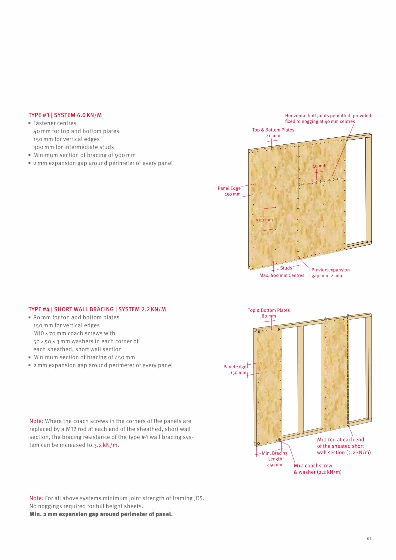
TYpE #3 | SYSTEM 6.0 kn/M
TYpE #4 | SHORT WAll BRAcInG | SYSTEM 2.2 kn/M
Fastener centres 40 mm for top and bottom plates 150 mm for vertical edges 300 mm for intermediate studs minimum section of bracing of 900 mm 2 mm expansion gap around perimeter of every panel
80 mm for top and bottom plates 150 mm for vertical edges m10 × 70 mm coach screws with 50 × 50 × 3 mm washers in each corner of each sheathed, short wall section minimum section of bracing of 450 mm 2 mm expansion gap around perimeter of every panel
Top & Bottom Plates40 mm
Horizontal butt joints permitted, providedfixed to nogging at 40 mm centres
Provide expansion gap min. 2 mm
Panel Edge150 mm
300 mm
Max. 600 mm CentresStuds
40 mm
Min. Bracing Length
450 mm M10 coachscrew & washer (2.2 kN/m)
M12 rod at each end of the sheated short wall section (3.2 kN/m)
Panel Edge150 mm
Top & Bottom Plates80 mm
note: For all above systems minimum joint strength of framing JD5. no noggings required for full height sheets.Min. 2 mm expansion gap around perimeter of panel.
note: Where the coach screws in the corners of the panels are replaced by a m12 rod at each end of the sheathed, short wall section, the bracing resistance of the Type #4 wall bracing sys-tem can be increased to 3.2 kn/m.
07
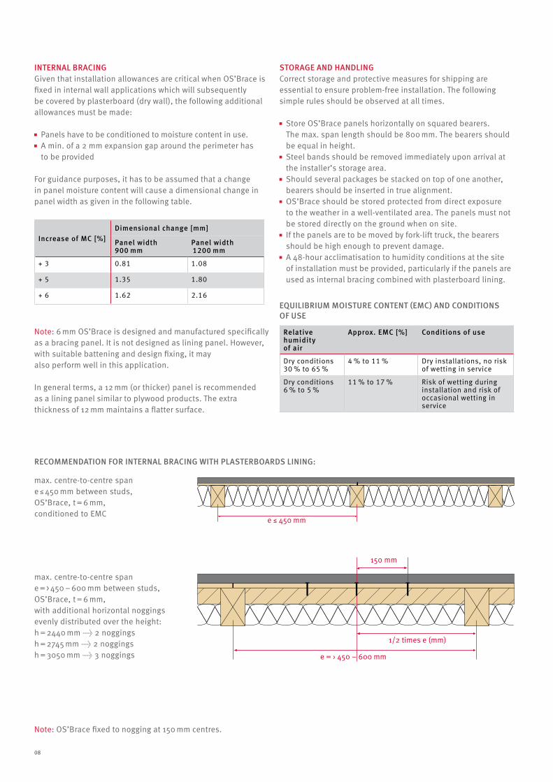
InTERnAl BRAcInGgiven that installation allowances are critical when os’brace is fixed in internal wall applications which will subsequently be covered by plasterboard (dry wall), the following additional allowances must be made:
panels have to be conditioned to moisture content in use. a min. of a 2 mm expansion gap around the perimeter has
to be provided
For guidance purposes, it has to be assumed that a change in panel moisture content will cause a dimensional change in panel width as given in the following table.
note: 6 mm os’brace is designed and manufactured specifically as a bracing panel. it is not designed as lining panel. however, with suitable battening and design fixing, it may also perform well in this application.
in general terms, a 12 mm (or thicker) panel is recommended as a lining panel similar to plywood products. The extra thickness of 12 mm maintains a flatter surface.
Increase of Mc [%]Dimensional change [mm]
panel width 900 mm
panel width 1200 mm
+ 3 0.81 1.08
+ 5 1.35 1.80
+ 6 1.62 2.16
REcOMMEnDATIOn FOR InTERnAl BRAcInG WITH plASTERBOARDS lInInG:
max. centre-to-centre span e ≤ 450 mm between studs, os’brace, t = 6 mm, conditioned to emc
max. centre-to-centre span e = > 450 – 600 mm between studs, os’brace, t = 6 mm, with additional horizontal noggings evenly distributed over the height:h = 2440 mm → 2 noggingsh = 2745 mm → 2 noggingsh = 3050 mm → 3 noggings
note: os’brace fixed to nogging at 150 mm centres.
STORAGE AnD HAnDlInGcorrect storage and protective measures for shipping are essential to ensure problem-free installation. The following simple rules should be observed at all times.
store os’brace panels horizontally on squared bearers. The max. span length should be 800 mm. The bearers should be equal in height. steel bands should be removed immediately upon arrival at
the installer’s storage area. should several packages be stacked on top of one another,
bearers should be inserted in true alignment. os’brace should be stored protected from direct exposure
to the weather in a well-ventilated area. The panels must not be stored directly on the ground when on site. if the panels are to be moved by fork-lift truck, the bearers
should be high enough to prevent damage. a 48-hour acclimatisation to humidity conditions at the site
of installation must be provided, particularly if the panels are used as internal bracing combined with plasterboard lining.
Relative humidity of air
Approx. EMc [%]
conditions of use
Dry conditions 30 % to 65 %
4 % to 11 % Dry installations, no risk of wetting in service
Dry conditions 6 % to 5 %
11 % to 17 % risk of wetting during installation and risk of occasional wetting in service
EquIlIBRIuM MOISTuRE cOnTEnT (EMc) AnD cOnDITIOnS OF uSE
e ≤ 450 mm
150 mm
e = › 450 – 600 mm
1/2 times e (mm)
e ≤ 450 mm
150 mm
e = › 450 – 600 mm
1/2 times e (mm)
08
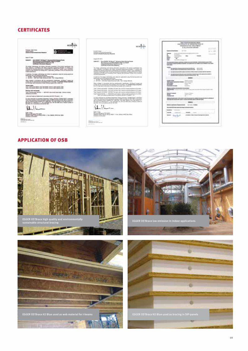
aPPLIcaTIoN oF osb
EGGER OS’Brace H2 Blue used as web material for I-beams EGGER OS’Brace H2 Blue used as bracing in SIp-panels
cerTIFIcaTes
EGGER OS’Brace high quality and environmentally sustainable structural bracing EGGER OS’Brace low emission in indoor applications
09
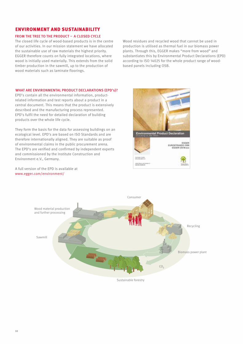
FROM THE TREE TO THE pRODucT – A clOSED cYclE
WHAT ARE EnvIROnMEnTAl pRODucT DEclARATIOnS (EpD’s)?
The closed life cycle of wood-based products is in the centre of our activities. in our mission statement we have allocated the sustainable use of raw materials the highest priority. egger therefore counts on fully integrated locations, where wood is initially used materially. This extends from the solid timber production in the sawmill, up to the production of wood materials such as laminate floorings.
epD’s contain all the environmental information, product- related information and test reports about a product in a central document. This means that the product is extensively described and the manufacturing process represented. epD’s fulfil the need for detailed declaration of building products over the whole life cycle.
They form the basis for the data for assessing buildings on an ecological level. epD’s are based on iso standards and are therefore internationally aligned. They are suitable as proof of environmental claims in the public procurement arena. The epD’s are verified and confirmed by independent experts and commissioned by the institute construction and environment e.v., germany.
a full version of the epD is available at www.egger.com/environment/
Wood residues and recycled wood that cannot be used in production is utilised as thermal fuel in our biomass power plants. Through this, egger makes “more from wood” and substantiates this by environmental product Declarations (epD) according to iso 14025 for the whole product range of wood-based panels including osb.
eNVIroNMeNT aND sUsTaINabILITY
10
DeLIVerY ProGraMMe
eGGer – THe eUroPeaN osb PLaNTs
The egger group is a 100 % family-owned business. since its inception in 1961 in st. Johann i.T., austria, egger has become a leading manufacturer of wood-based products on the european market. Today, egger has 17 plants in 7 european countries, about 7,200 employees, sales offices in all major industrial nations of the world and a global sales and distribution network serving over 85 countries worldwide.
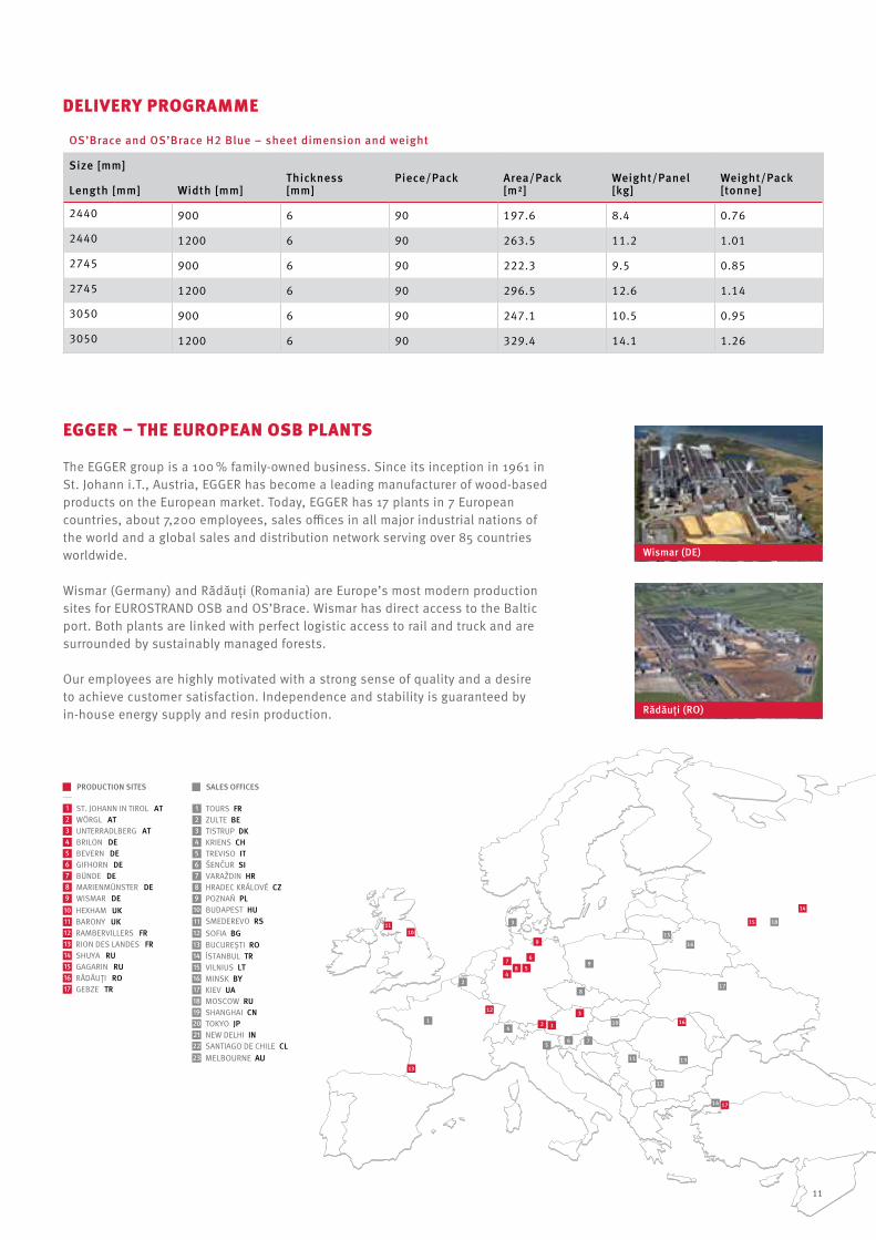
Wismar (germany) and rădăuţi (romania) are europe’s most modern production sites for eurosTranD osb and os’brace. Wismar has direct access to the baltic port. both plants are linked with perfect logistic access to rail and truck and are surrounded by sustainably managed forests.
our employees are highly motivated with a strong sense of quality and a desire to achieve customer satisfaction. independence and stability is guaranteed by in-house energy supply and resin production.
OS’Brace and OS’Brace H2 Blue – sheet dimension and weight
Size [mm] Thickness [mm]
piece/pack
Area/pack [m2]
Weight/panel [kg]
Weight/pack [tonne]length [mm] Width [mm]
2440 900 6 90 197.6 8.4 0.76
2440 1200 6 90 263.5 11.2 1.01
2745 900 6 90 222.3 9.5 0.85
2745 1200 6 90 296.5 12.6 1.14
3050 900 6 90 247.1 10.5 0.95
3050 1200 6 90 329.4 14.1 1.26
pRODucTIOn SITES SAlES OFFIcES
Wismar (DE)
Rădăuţi (RO)
melbourne Au
11
EGGER Holzwerkstoffe Wismar GmbH & co. kG am haffeld 1 23970 Wismar germany t +49 3841 301-0 f +49 3841 301-20222 [email protected]
en_
os’
brac
e_03
/14
subj
ect t
o te
chni
cal m
odifi
catio
ns a
nd a
men
dmen
ts. e
gg
er re
serv
e th
e rig
ht to
with
draw
or a
men
d th
e in
form
atio
n at
any
tim
e.
available from:
Sc EGGER România SRlstr. austriei 2po box 38725400 rădăuţi, jud. suceavaromaniat +40 372 438000f +40 372 [email protected]
www.egger.com/osbrace
EGGER AuSTRAlASIA pTY lTD po box 697 carlton south 3053 victoria australia t +61 448 200 013 [email protected]