Embed Size (px)
Citation preview

Quebec Overpass CollapseQuebec Overpass CollapseJuxtaposed to DeterioratingJuxtaposed to DeterioratingJuxtaposed to DeterioratingJuxtaposed to Deteriorating
Infrastructure in CanadaInfrastructure in Canada
Nemy BanthiaNemy Banthiayy((with assistance from Prof. Jacques Marchand)with assistance from Prof. Jacques Marchand)
The University of British ColumbiaThe University of British ColumbiaVancouver, CanadaVancouver, Canada
1 2
NE
N
S
W
3
Chronology:Chronology:
• September 30 2006 - Collapse of the south-September 30, 2006 Collapse of the southeast side of the overpass;
• October 1, 2006 – Beginning of the policeinvestigation;investigation;
• October 6 2006 – Appointment of theOctober 6, 2006 Appointment of thecommissioners (Johnson, Nicolet & Couture);
4
• October 18, 2007 – Publication of the report.
Main characteristics of the structure
Central span – 90 feetCentral span 90 feet
West abutment East abutmentWest abutment East abutment
5
Main Characteristics of the Structure
6
C til 13 f tCharacteristics of the Structure
BeamDisturbed
Cantilever – 13 feet
Beamzone
Disturbedregion
Neoprenepadspads
Beam seat
7
Characteristics of the Structure
8
Characteristics of the Structure
9Extrait du feuillet 29, Plans de Desjardins Sauriol et AssociésViaduc de la Concorde
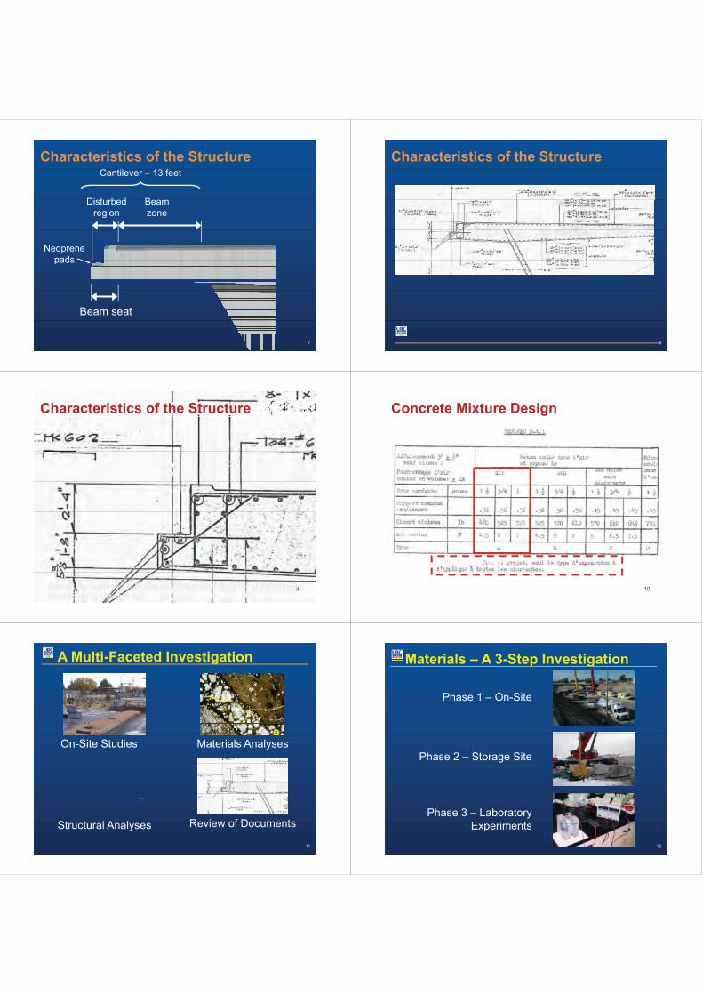
Concrete Mixture Design
10
A Multi-Faceted Investigation
Materials AnalysesOn-Site Studies
Structural Analyses Review of Documents
11
Structural Analyses Review of Documents
Materials – A 3-Step Investigation
Phase 1 – On-Site
Phase 2 – Storage Site
Phase 3 – LaboratoryExperiments
12
Experiments
Phase 1I it tiIn-situ operations
13 14
15
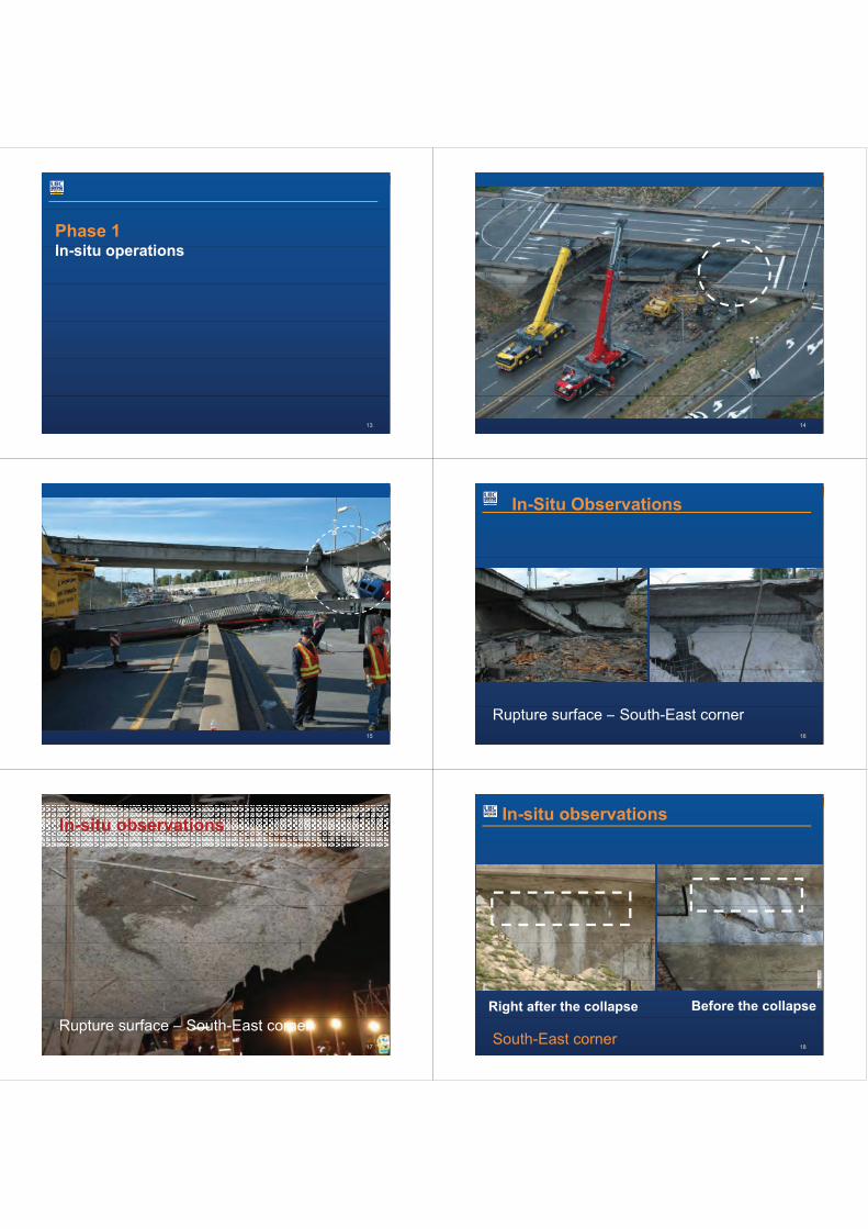
In-Situ Observations
16
Rupture surface – South-East corner
In-situ observations
17
Rupture surface – South-East corner
In-situ observations
Right after the collapse Before the collapse
18South-East corner

In-situ observations
19North-East corner
Coring Operations
19 N
North-West North-East8
5 4 7
19-N
9A 10
8
1212
3
19-S
9B
6
132
20South-West South-East
6111
Coring operations
T h t i t• To characterize concrete
T d t t th f ki l21
• To detect the presence of a cracking plane
Coring operationsm
m19
0
Core hole A
2222Core A – Site 8
Core hole ASite 8
Extraction of Large Pieces
S th E t N th E t23
South-East corner North-East corner
NDT Measurements using Radar
• Both abutmentsBoth abutments• Top surface
24
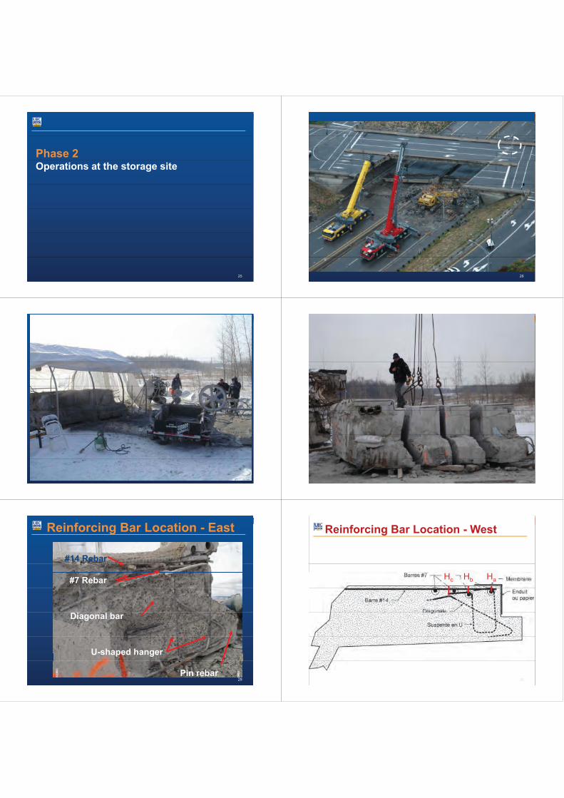
Phase 2Operations at the storage site
25 26
27 28
Reinforcing Bar Location - East
#14 Rebar
#7 Rebar
Diagonal bar
U-shaped hanger
29Pin rebar
Reinforcing Bar Location - West
HaHbHc
30

The 3 Main Causes of the Collapse:
1. Improper rebars installation during construction
The incorrect placement of the U-shaped hangersd di l b t d f kand diagonal bars created a zone of weakness
that extended deep inside the thick slab.
31
Concrete Degradation – South-EastCornerCorner
32
Phase 3Material Characterization
33
Concrete Characterization
Main objectivesMain objectives
• To characterize the properties of concrete• To characterize the properties of concrete(on cores extracted from « sound » areas)
• To identify the cause(s) of the concretedegradation along the rupture planedegradation along the rupture plane
34
Compressive Strength Determination(CSA A23 2 9C)(CSA A23.2-9C)
Site Cores Orientation Results
1 3 Horizontal 28 7 MPa1 3 Horizontal 28,7 MPa2 2 Vertical 28,2 MPa3 3 Vertical 31,3 MPa4 3 Horizontal 40,5 MPa5 3 Horizontal 31,3 MPa7 3 Horizontal 27 3 MPa7 3 Horizontal 27,3 MPa
9A 3 Vertical 27,7 MPa9B 3 Vertical 30,7 MPa10 3 Vertical 35,1 MPa11 3 Horizontal 29,4 MPa13 2 V ti l 31 6 MP
CompressionMean: 31 1 MPa
35
13 2 Vertical 31,6 MPaGirders 6 Variable 51,4 MPa
Mean: 31,1 MPaSpec. = 27,8 MPaat 28 days
Petrographic Examination
• Porous concrete (W/C 0,55)W ll h d t d t• Well hydrated concrete
• Very few microcracksN i f ASR• No signs of ASR
Frost attack was identified asthe main cause of concretedegradation at the vicinity of therupture plane.
36

Air-Void Characteristics
Site Air Spec.f (
Spacing
CNO CNE
9A 108
5 4 7
Cont.(%)
surface(mm-1)
factor(µm)
1 3,8 14,6 368 CSO CSE
9B6132
111
3
Air content (%)Mean: 5,2
, ,2 4,7 10,1 5133 6,3 12,8 351
CSO CSE111
Standard dev.: 1,8
Specific surface (mm-1)
4 2,0 11,0 6835 5,6 11,2 4117 4 4 13 4 377 Mean: 12,9
Standard dev.: 2,2
S i f t ( )
7 4,4 13,4 3779A 5,1 16,0 29410 5,2 16,1 295
Spacing factor (µm)Mean: 397 230Standard dev.: 119 37
11 9,1 10,7 31713 5,8 12,8 356
Scaling Resistance
38
Permissible limit0.5 kg/m2 after 56 cycles
Results7 kg/m2 after 21 cycles
The 3 Main Causes of the Collapse:
2. Low quality of concrete
The concrete used for the construction of theabutments did not have the necessaryabutments did not have the necessarycharacteristics to resist freezing and thawingcycles in presence of de icing chemicalscycles in presence of de-icing chemicals.
39
The 3 Main Causes of the Collapse:
3. Improper rebar detailing during design
In the structure as designed, thet ti f b thconcentration of numerous rebars on the
same plane in the upper part of the abutmentt d l f k hcreated a plane of weakness where
horizontal cracking could occur.
40
The 3 Main Causes of the Collapse
1. Improper rebars installation duringconstruction
2. Low quality of concrete
3. Improper rebar detailing during design
41
Influence of the Collapse:
All structures built at that time using
Influence of the Collapse:
All structures built at that time usingthe same structural system were alltaken out of servicetaken out of service….
42

Trial of the CollapseAlthough it was a police
Trial of the Collapseg p
investigation, no one was foundcriminally responsiblecriminally responsible..
43
Compensation for the VictimsCompensation for the VictimsCompensation was paid to thep pvictims of the collapse. Totalcompensation for the survivorscompensation for the survivorsof the 5 deceased was about$1 5 million$1.5 million.
44
Responsibility of Road administratorsp y
Significant new funding is nowavailable for periodic conditionavailable for periodic conditionassessment, health monitoring andresearchresearch.
45
Required Future ResearchRequired Future Research
Development of advanced tools forDevelopment of advanced tools forhealth monitoring and conditionassessment of structure.
Creation of a strategic network on thistopic.topic.
46
Infrastructure Crisis inInfrastructure Crisis inCanada
Civil InfrastructureCivil InfrastructureAviationBridgesDamsDrinking WaterH d W tHazardous WastesRoadsEnergySchoolsSchoolsNavigation WaterwaysPublic Parks and RecreationSecuritySecuritySolid WasteTransitWaste Water

Infrastructure DeficitInfrastructure Deficit Hypothesis: Ayp
decline in the public capital formation(i.e. infrastructure) lowers privatesector productivity and thereforesector productivity and, therefore,lowers a nation’s real income andweaken its competitiveness.p
Infrastructure in CanadaInfrastructure in Canada
59% of Canada’sinfrastructure is morethan 40 years oldthan 40 years old
As per StatisticsCanada, 37 years is, ythe expected averagelife of a structure inCanada.
Infrastructure in CanadaInfrastructure in Canada
There are approximatelyThere are approximately10,000 deficient bridges witha total repair /strengtheningcost of $44 billion.
Th 4000 kiThere are 4000 parkinggarages needing immediateattentionattention.
Infrastructure in Canada
Canada’s current Infrastructure Backlog$Canada s current
infrastructure deficit is$125 billion (and
0.0
($ Billions)
(growing annually by$2 billion), which is 6-10 f
-150.0
-75.0
Prediction 2002
10 times the level ofall annual governmentinfrastructure budget
-225.01985 2002 2009 2027
Actual 2009
infrastructure budgetcombined.
Prediction in 2002 which has
Estimate Actual
Poly. (Estimate) Poly. (Actual)
Prediction in 2002 which hasalready proven to be an
underestimation
Why are we in such dire straits?
Deterioration and aging of structural systemsdue to weather, fatigue, pollution, structuraldue to weather, fatigue, pollution, structuralsettlement and now global warming;Construction mistakes;Code changes (structural dynamics, seismicdesign, etc.);Loading changes; andFunctional Obsolesce.
Influence of Global Warming onConcrete StructuresConcrete StructuresIncrease in atmospheric CO2 levels from 370 ppm to1000 ppm
Increased Corrosion RatesIncreased Carbonation
Increase in temperature by over 50CIncreased ShrinkageIncreased ShrinkagePorous Microstructure and High PermeabilityIncreased Corrosion Rates
Increased Water LevelsIncreased SaturationGreater Scour

Scour Detection and Measurement Needs
DamageI t
DeteriorationC i• Impact
• Cracking• Fatigue
O l d
• Corrosion• Water absorption• Loss of prestress• Unintended structural behavior• Overload
• Scour• Seismic
Unintended structural behavior• Soil stiffness
• Settlement• Foundation• Inoperative bearings• Movement/Lack of
movement
NDT for Detection of Damage andDeteriorationDeterioration
Damage Deterioration• Cracking• Fatigue• Excessive
Di l t /
• Rebar Corrosion• Water absorption• AAR/Freeze-Thaw/Scaling
Displacements/Settlement
• Scour• Foundation Issues
• Overall integrity
• Foundation Issues
Limitations of Current Inspections
• Condition states still based solely upon visualinspection
• Invisible deterioration damage or distress not detected• Invisible deterioration, damage or distress not detectedor measured
• Operational performance not measuredOperational performance not measured• Vulnerability and reliability not adequately addressed
Canadian Research ObjectivesCanadian Research Objectives
To improve safety (and security) of concrete bridgesthrough an accurate assessment of bridge conditionand performance.p
Develop advanced health monitoring tools based onremote/onsite measurements that areperiodic/continuousperiodic/continuous.
Relate health monitoring findings to structuralcondition.
Use advanced modeling tools to reliably forecastbridge performance, maintenance needs, etc. esp. inthe light of impending global warmingthe light of impending global warming.
Safety, Security and Sustainability ofBridges: 2 Themes
Structural Health Monitoring(Global)
Materials Health Monitoring(Local)
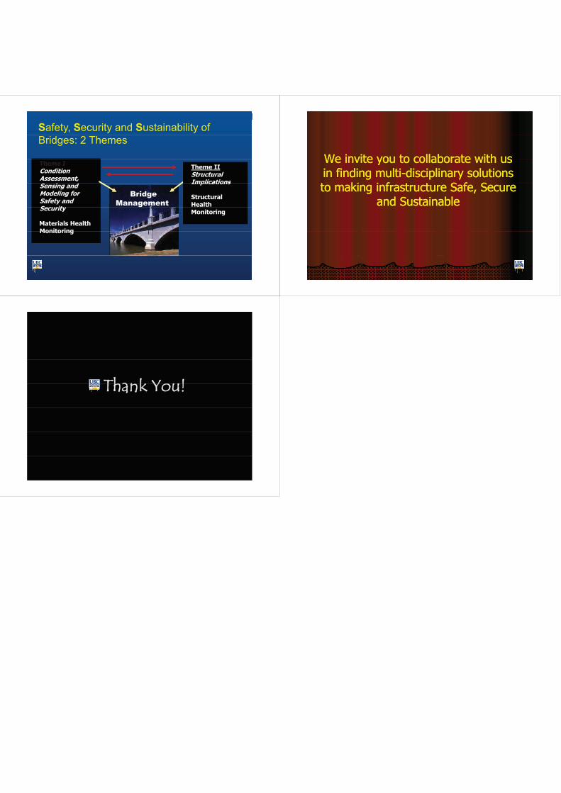
Safety, Security and Sustainability ofBridges: 2 Themes
Theme IConditionAssessment,
i d
Theme IIStructuralImplicationsSensing and
Modeling forSafety andSecurity
BridgeManagement
Implications
StructuralHealthSecurity
Materials HealthMonitoring
Monitoring
Monitoring
We invite you to collaborate with usWe invite you to collaborate with usWe invite you to collaborate with usWe invite you to collaborate with usin finding multiin finding multi--disciplinary solutionsdisciplinary solutionst ki i f t t S f St ki i f t t S f Sto making infrastructure Safe, Secureto making infrastructure Safe, Secure
and Sustainableand Sustainable
TThhaannkk YYoouu!!TThhaannkk YYoouu!!