Embed Size (px)
Citation preview
Daishsat Geodetic Surveyors – 09030 Quasar Resources – Curtin Springs Gravity Survey
QUASAR RESOURCES CURTIN SPRINGS GRAVITY SURVEY
July 2009 Report Number 09030
A. McCarthy
CLIENT
QUASAR RESOURCES
CLIENT CONTACT John Caon
Senior Geophysicist Suite 2 Level 4/25 Grenfell Street
Adelaide SA 5000 Phone (08) 8110 0570
SURVEY CONTRACTORDAISHSAT PTY. LTD
P.O. Box 766 MURRAY BRIDGE S.A. 5253
Tel: (08) 8531 0349 Fax: (08) 8531 0684
CONTRACTOR CONTACT Mr. David Daish
Mob: 0418 800 122 Email: [email protected]
CONFIDENTIAL
Daishsat Geodetic Surveyors – 09030 Quasar Resources – Curtin Springs Gravity Survey
TABLE OF CONTENTS
1. INTRODUCTION ................................................................................... 1
2. SURVEY OVERVIEW ........................................................................... 1
3. PERSONNEL AND EQUIPMENT ......................................................... 3
3.1 Personnel ................................................................................................................... 3
3.2 Survey equipment ..................................................................................................... 3
3.3 Support vehicles ....................................................................................................... 3
3.4 Helicopter ................................................................................................................... 4
3.5 Accommodation ........................................................................................................ 4
3.6 Communications ....................................................................................................... 4
4. GPS SURVEYING AND PROCESSING ............................................... 5
4.1 Set out of the grid ...................................................................................................... 5
4.2 Survey datum and control ........................................................................................ 5
4.3 Processing of the position and level data .............................................................. 5
4.4 GPS Performance ...................................................................................................... 7
5. GRAVITY SURVEYING AND PROCESSING ....................................... 8
5.1 Gravity data acquisition ........................................................................................... 8
5.2 Gravity base station .................................................................................................. 8
5.3 Gravity data processing ........................................................................................... 8
5.4 Gravity meter calibration and scale factors ........................................................... 9
6. RESULTS ............................................................................................ 10
6.1 Stations Surveyed and Survey Progress .............................................................. 10
6.2 Data Repeatability ................................................................................................... 10
APPENDIX A – PLOTS AND IMAGES .................................................... 11
APPENDIX B – REPEAT TABULATION AND ANALYSIS ...................... 16
APPENDIX C – SURVEY SPECIFICATIONS ........................................... 17
APPENDIX D – BASE STATION INFORMATION .................................... 18
APPENDIX E – DATA CD ......................................................................... 20

Daishsat Geodetic Surveyors – 09030 Quasar Resources – Curtin Springs Gravity Survey 1
1. INTRODUCTION
A precision GPS-Gravity survey was carried out by Daishsat Geodetic Surveyors between the 3rd and 8th of July on behalf of Quasar Resources Pty Ltd. A total of 1,234 stations were surveyed to the North of Curtin Springs Station in the Northern Territory. Gravity data were acquired using Scintrex CG-5 gravity meters. Position and level data were obtained using Leica 1230GG geodetic grade GPS receivers collecting GPS and GLONASS positional information. All receivers were operating in post-processed kinematic mode. Data was acquired using Daishsat helicopter-borne survey methods. Gravity data were reduced using standard reductions on the ISOGAL84 gravity network. Post processed GPS data was exported as MGA coordinates with levels expressed as metres above the Australian Height Datum.
2. SURVEY OVERVIEW
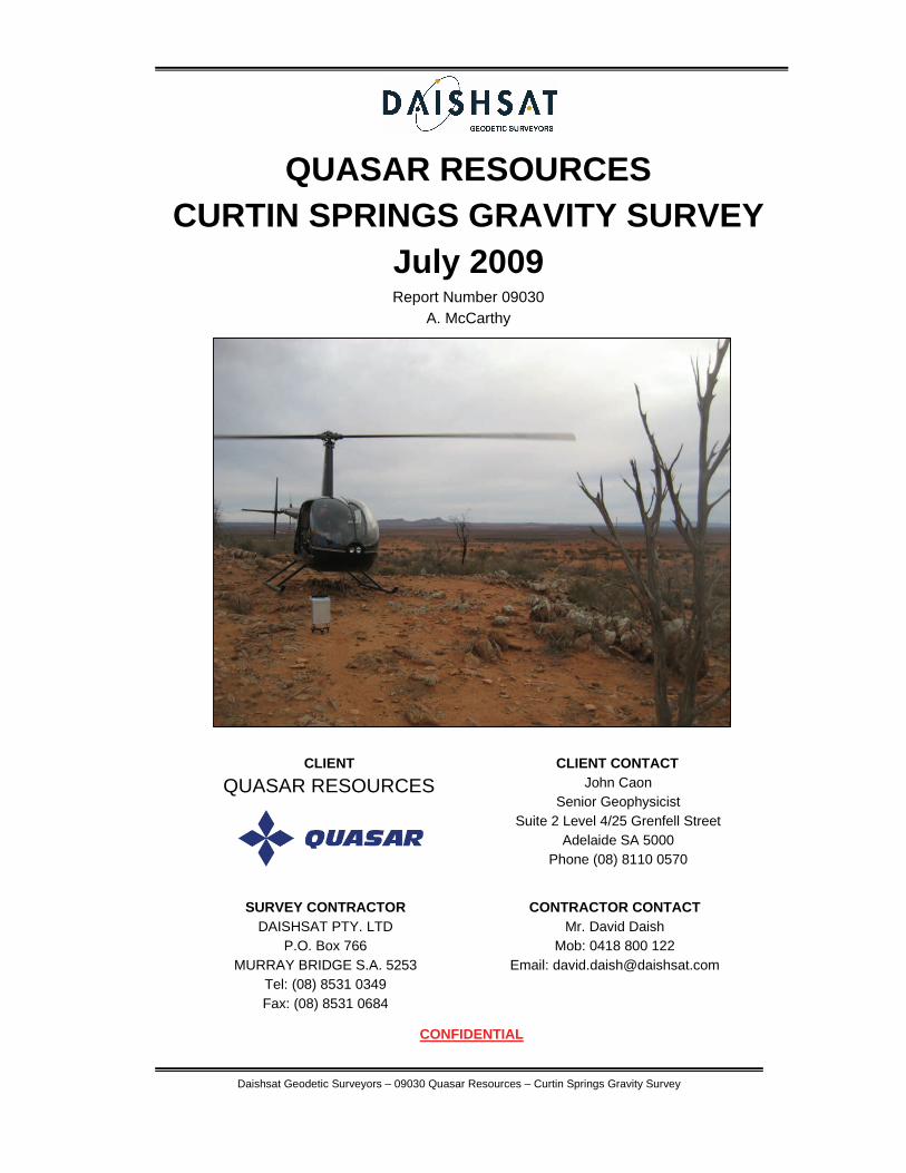
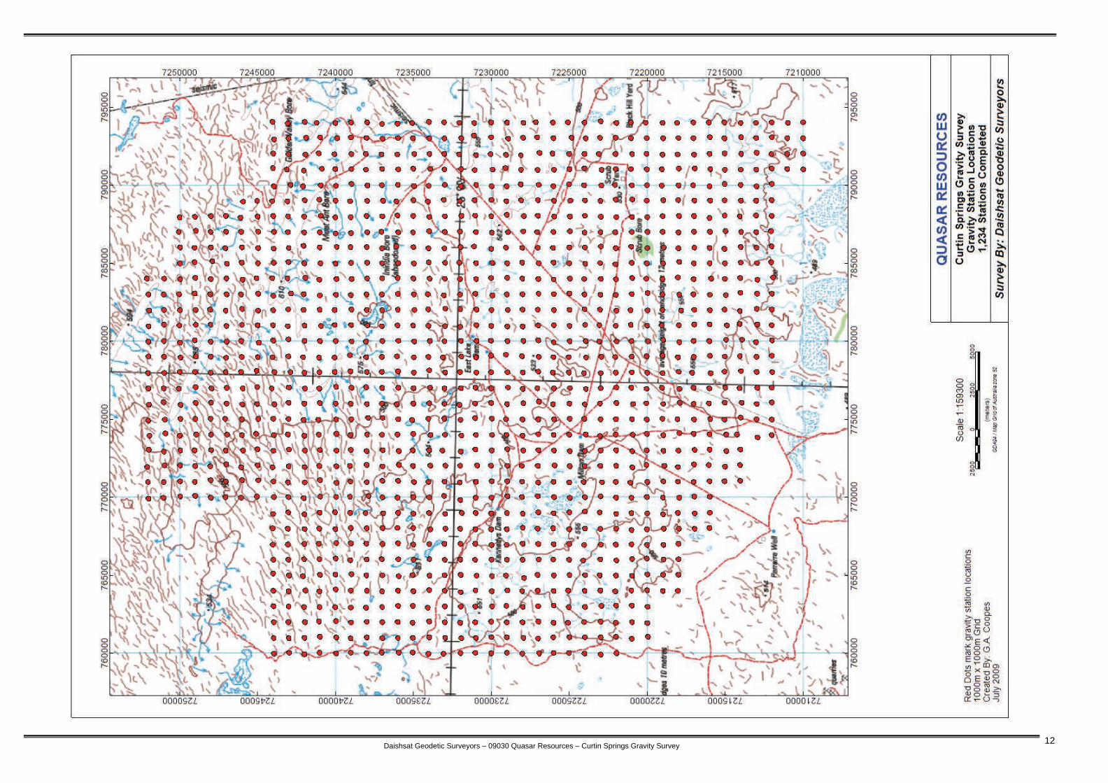
The Quasar Curtin Springs gravity survey covered an area of approximately 1200 km2 in the central area of the Northern Territory. The survey was centered 50km north of Curtin Springs roadhouse located on the Lasseter Highway 100km east of Yulara. The location of the survey is shown in Figure 1. Appendix A contains a plot of the final station locations and Appendix C contains the specifications for the survey.
Photo 1: Typical terrain in the survey area.

Daishsat Geodetic Surveyors – 09030 Quasar Resources – Curtin Springs Gravity Survey 2
Daishsat Geodetic Surveyors – 09030 Quasar Resources – Curtin Springs Gravity Survey 3
3. PERSONNEL AND EQUIPMENT
3.1 Personnel The supervisor in charge of the project was Mark Rosewall. Mark was responsible for daily management of the job and for nightly data processing to ensure quality and integrity. Gravity and GPS measurements were carried out by: Jon Nankivell Mark Rosewall The Helicopter pilots used for the project were: Lee Mitchell Chris Hall Final data reduction, inspection and reporting were performed by the company Geophysicist, Grant Coopes.
3.2 Survey equipment The following survey equipment was utilised on the gravity survey: - Scintrex CG-5 digital gravity meters (A and N meters) - Leica 1230GG dual frequency GPS receivers with GLONASS capability - Notebook computers for data processing and backup - Garmin 296 GPS receivers for helicopter navigation - Garmin Handheld GPS receivers for vehicle navigation - Various chargers, solar cells and batteries
3.3 Support vehicles Due to the type of terrain and remote locations, 4WD Landcruiser and 4WD Isuzu Trucks were utilized as support vehicles for the surveys. To maintain the high Daishsat safety record, vehicles were fitted with a range of safety equipment including: - One 20l jerry can of water - Dual fuel tanks - Two spare tyres - UHF radio and satellite phone with car kit - Self-recovery equipment including winches, snatch straps chains etc. - Tyre pliers to effect tyre repairs in the field - Tools and spares to enable field repairs as necessary - Survival kits with EPIRB emergency locator beacons - Trans track satellite vehicle monitoring and reporting systems
Daishsat Geodetic Surveyors – 09030 Quasar Resources – Curtin Springs Gravity Survey 4
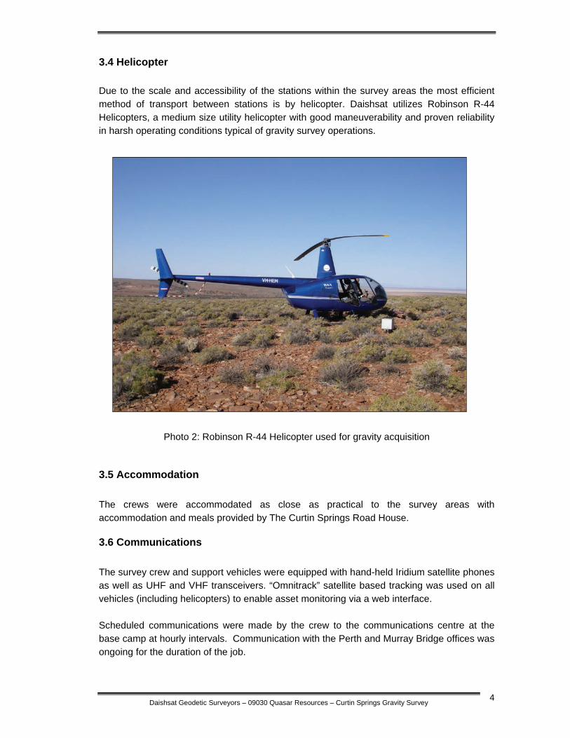
3.4 Helicopter Due to the scale and accessibility of the stations within the survey areas the most efficient method of transport between stations is by helicopter. Daishsat utilizes Robinson R-44 Helicopters, a medium size utility helicopter with good maneuverability and proven reliability in harsh operating conditions typical of gravity survey operations.
Photo 2: Robinson R-44 Helicopter used for gravity acquisition
3.5 Accommodation The crews were accommodated as close as practical to the survey areas with accommodation and meals provided by The Curtin Springs Road House.
3.6 Communications The survey crew and support vehicles were equipped with hand-held Iridium satellite phones as well as UHF and VHF transceivers. “Omnitrack” satellite based tracking was used on all vehicles (including helicopters) to enable asset monitoring via a web interface. Scheduled communications were made by the crew to the communications centre at the base camp at hourly intervals. Communication with the Perth and Murray Bridge offices was ongoing for the duration of the job.

Daishsat Geodetic Surveyors – 09030 Quasar Resources – Curtin Springs Gravity Survey 5
4. GPS SURVEYING AND PROCESSING
4.1 Set out of the grid This was done concurrently with the gravity data acquisition using navigation grade receivers operating in autonomous mode. Where possible, the readings were taken as close to the ideal coordinates as possible. As the receivers were operating in autonomous mode, set out accuracy was usually better than 10m. Raw kinematic GPS data were logged by twin dual-frequency Leica 1230GG receivers inside the helicopter cabin, with the GPS antennas mounted on the tail boom. Static GPS data was logged at the base station using two Leica System 1230GG GPS receivers for later post-processing. The Leica 1230GG is a new generation GPS receiver making use of both the traditional US GPS satellite constellation and the newly available GLONASS satellite constellations for higher positional accuracy and reduced periods of poor satellite coverage. Repeat stations were placed throughout the surveys to monitor any variations in positional accuracy. Repeats are placed with a washer tied with flagging and marked with the station number was used for future identification. At each station, the station number, position and RL were recorded digitally by the crew.
4.2 Survey datum and control The gravity surveying, and hence any gravity reductions, used the Australian Height Datum (AHD) as the reference datum. New GPS/Gravity base stations were established at each of the three bases using three days worth of static data and connections to ITRF stations using Geoscience Australia’s online GPS processing system, AUSPOS. For more information on this system, please visit the Geoscience Australia website at http://www.ga.gov.au/geodesy/sgc/wwwgps/. Final deviations of better than 5mm were obtained for x, y and z, for all occupations. Appendix D contains the GPS base station information.
4.3 Processing of the position and level data The raw GPS data was recorded onto the internal RAM of the GPS receivers. The data was downloaded nightly onto a laptop computer for post-processing using Waypoint’s premier processing software package – Grafnav V7.80. Waypoint combines the processing components, GrafNav and GrafNet, in a complete package. GrafNav processes data for one baseline (e.g. one base and one remote). GrafNav is normally used for kinematic data which it is extremely well suited for. It can also process single static baselines. Receiver types can be mixed and matched via the use of a common format. This component of Waypoint was used for processing the kinematic data acquired each day.
Daishsat Geodetic Surveyors – 09030 Quasar Resources – Curtin Springs Gravity Survey 6
GrafNav and GrafNet share the same processing engine that has been under continuous development since its original inception by Waypoint in 1992. The core of this robust engine is its carrier phase kinematic (CPK) Kalman filter. Some of the major advantages of Waypoint's kernel are:
Fast processing - The GrafNav kernel is one of the fastest on the market. It will process ~0.8 epochs per MHz per second on a Pentium II.
Robust Kalman filter - From experience with processing GPS data from fast jets and NASA sounding rockets, the processing kernel has become extremely robust. Efforts have been made to account for all of the various data error possibilities given the different types of GPS receivers that GrafNav/GrafNet can handle.
Reliable OTF - Waypoint's on-the-fly (OTF) algorithm, called Kinematic Ambiguity Resolution (KAR), has had years of development and stresses reliability. Variations are implemented for both single and dual frequencies, and numerous options are available to control this powerful feature
Accurate Static Processing - Three modes of static processing are implemented in the processing kernel. Fixed static is the most accurate. A quick static solution is also available as an alternative, while the float and iono-free float solution is useful for long baselines.
Dual Frequency - Full dual frequency support comes with GrafNav/GrafNet. For ambiguity resolution, this entails wide/narrow lane solutions for KAR, fixed static and quick static. Ionospheric processing is very important with the peak of the ionosphere's cycle occurring in 2000. The GrafNav kernel implements two ionospheric processing modes including the iono-free and relative models. The relative model is especially useful for airborne applications where initialization is near the base station, and this method is much less susceptible to L2 phase cycle slips.
Forward and Reverse - Processing can be performed in both the forward and reverse directions. Both GrafNav and GrafNet also have the ability to combine these two solutions to obtain a globally optimum one.
Velocity Determination - Since the GrafNav kernel includes the L1 Doppler measurement in its Kalman filter, velocity determination is very accurate. In addition to this, a considerable about of code has been added specifically for the detection and removal of Doppler errors. Long Baseline - Because precise ephemeris and dual frequency processing is supported; long baselines accuracies can be as good as 0.1 PPM.
For more information about Waypoint processing software, and in particular, GrafNav, please visit the Waypoint http://www.waypnt.com/grafnav_d.html. MGA94 coordinates were obtained by simply projecting the GPS-derived WGS84 coordinates using a UTM projection with zone 52S. For all practicable purposes, the WGS84 geodetic coordinates are equivalent to GDA94 geodetic coordinates, so no transformation is necessary. For more information about GDA94 and MGA94, please visit http://www.ga.gov.au/geodesy/datums/gda.jsp.
Daishsat Geodetic Surveyors – 09030 Quasar Resources – Curtin Springs Gravity Survey 7
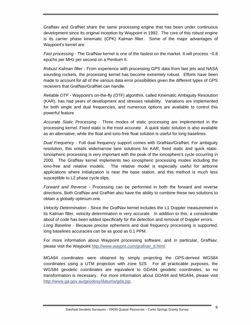
AHD heights were calculated via Waypoint software using the latest geoid model for Australia, AUSGEOID98. Information about the geoid and the modeling process used to extract separations (N values) can be found at http://www.ga.gov.au/geodesy/ausgeoid/. To obtain AHD heights, the modeled N value is subtracted from the GPS derived WGS84 ellipsoidal height (Figure 2).
HAHD=hWGS84-N
Figure: 2: Geoid-Ellipsoid separation
4.4 GPS Performance Performance from the 1230GG receivers was excellent. There were no stations that required repeating due to GPS failure or poor coordinate quality.
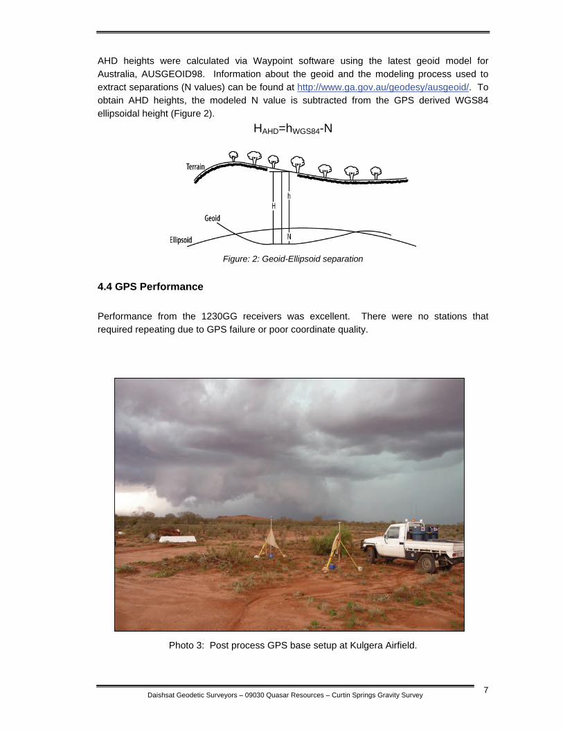
Photo 3: Post process GPS base setup at Kulgera Airfield.
Daishsat Geodetic Surveyors – 09030 Quasar Resources – Curtin Springs Gravity Survey 8
5. GRAVITY SURVEYING AND PROCESSING
5.1 Gravity data acquisition Gravity observations were made concurrently with the GPS measurements. Two observations were made for each station, with each observation consisting of a 20-second or greater stacking time. Multiple observations were made at each station so that any seismic or instrumental noise could be immediately detected. The tolerance between readings was set at 0.05 of a dial reading (0.05 mGals). Vertical and horizontal levels were restricted to 5 arc seconds at all times. At each station, the station number, time and two gravity readings (in dial units) were recorded in DAISHSAT carbon-copy gravity field books. The Scintrex meters also automatically record the station, time and readings digitally to allow for downloading to computer.
5.2 Gravity base station
Gravity base stations were used for calculation of absolute gravity and drift determination. A new gravity base station – Base 0308 – was established at the Kulgera Airstrip. The observed gravity value for this base was calculated through completing multiple B-A-B gravity loops to AFGN stations located at the Yulara Airport Terminal. The expected accuracy of the tie control surveys is better than 0.01 mGals. Details of the gravity bases established for the survey are contained in Appendix D.
When in the field, base station readings were taken in the morning before the first observation and at evening after the last observation. When taking a base station reading, the observed gravity values were stacked over 60 seconds to ensure accuracy. Observations were repeated until the readings repeated to 0.010 of a dial reading or less.
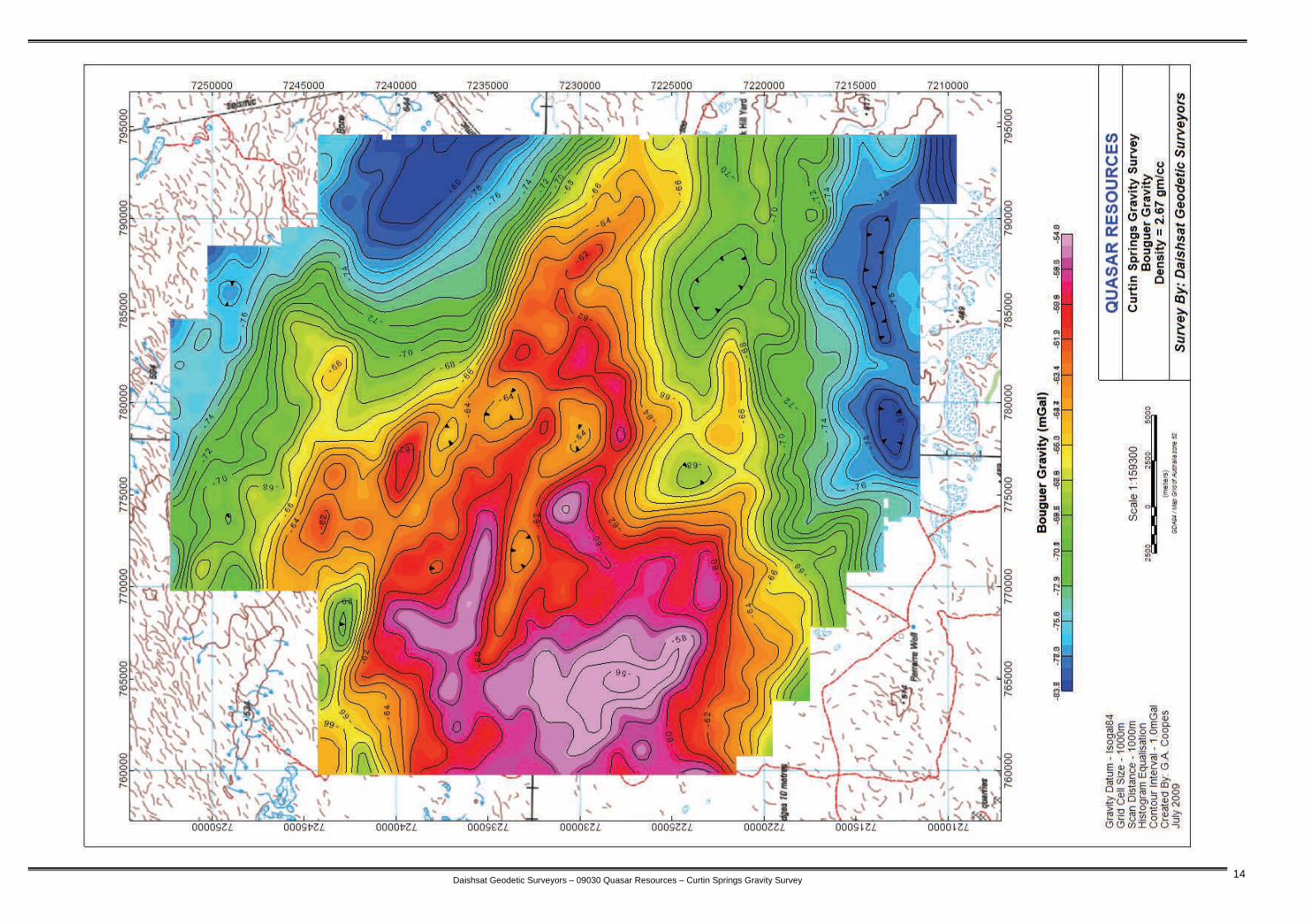
5.3 Gravity data processing Raw gravity data were processed on a daily basis to check for quality and integrity. This interim process produced a set of Bouguer Gravity values, which were contoured and imaged to provide a check for any anomalous readings that would need repeating. Geosoft GRAVRED software was used for the gravity reduction in the field. Other software used on this project includes ArcView, ChrisDBF, and Oasis Montaj. The formulae used in the gravity reduction are listed below: Instrument scale factor: This correction was used to correct a gravity reading (in dial units) to a relative milliGal value based on the meter calibration. Tidal correction: This correction was used to correct for background variations due to changes in the relative position of the moon and sun. The Scintrex calculated ETC was removed and a new ETC calculated using Geosoft Formulae and the surveyed GPS latitude. The formula is too complex to list here.
Daishsat Geodetic Surveyors – 09030 Quasar Resources – Curtin Springs Gravity Survey 9
Instrument Drift: Since gravity meters are mechanical, they are prone to drift (extension of the spring with heat, obeying Hooke’s law). If two base readings are taken one can assume that the drift between the two readings is linear and can therefore be calculated. The drift and tidal corrected value is referred to as the observed gravity. Theoretical Gravity: The theoretical value of gravity was calculated using the 1967 variant of the International Gravity Formula and used to latitude correct the observed gravity.
Gt=978031.856 *(1+0.005 278 895*sin²φ+0.000 023 462*sin4φ)
where φ represents degrees of latitude
Free-Air Correction: Since gravity varies inversely with the square of distance, it is necessary to correct for changes in elevation between stations to reduce field readings to a datum surface (in this case, AHD).
AHDhFA ×= 308596.0 Bouguer Correction: This correction accounts for the attraction of material between the station and datum plane that is ignored in the free-air calculation. A value of 2.67 gm/cc was used in the correction.
AHDhBC ××= ρ0419088.0 where ρ = density (2.67 gm/cc)
Free Air Gravity: This is obtained by applying the free air correction (FAC) to the observed gravity reading.
FAG=GOBSG84-Gt+FAC Bouguer Gravity: This is obtained when all the preceding reductions or corrections have been applied to the observed gravity reading.
BG267=GOBSG84-Gt+FAC-BC
5.4 Gravity meter calibration and scale factors The gravity meter used had previously been calibrated on either the South Australian or Western Australian gravity calibration ranges. A derived scale factor from these calibrations is shown below: Meter Serial No. Scale Factor (A) 24921 1.000314 (N) 40373 1.000241

Daishsat Geodetic Surveyors – 09030 Quasar Resources – Curtin Springs Gravity Survey 10
6. RESULTS
Raw and processed GPS and gravity data are contained on CDROM as Appendix E. Hardcopy plots of station location and coloured images are contained in Appendix A.
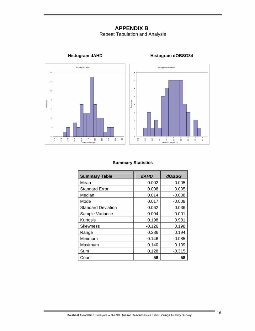
6.1 Stations Surveyed and Survey Progress In total 1292 stations were acquired across the survey area consisting. Of these stations at total of 58 were revisited to ensure data accuracy and quality. A brief production summary for the survey is show in Table 1 below. Production was excellent with the helicopter crew averaging over 245 stations per day. Due to CASA regulations restricting duty hours for pilots, some time was lost from direct production although the crews used this downtime to conduct helicopter and equipment maintenance and review the acquired data. There was no downtime due to geophysical or GPS equipment failure.
Curtin Springs Gravity Survey 2009 Gravity stations acquired (including repeats) 1292stations Gravity station repeats 584.7% New gravity stations acquired 1234stations Total accidents 0accidents Total hours lost from accidents 0hours
Table 1: Gravity Production Summary
6.2 Data Repeatability Analysis of the repeat data shows that measurement repeatability is very good for both GPS and gravity observations. Appendix B contains histograms and summary statistics from the analysis. Based on the repeat data, one can assume the following typical accuracies for the observables:
Z position observation: < 0.062m Gravity observation: < 0.036mGals

Daishsat Geodetic Surveyors – 09030 Quasar Resources – Curtin Springs Gravity Survey 11
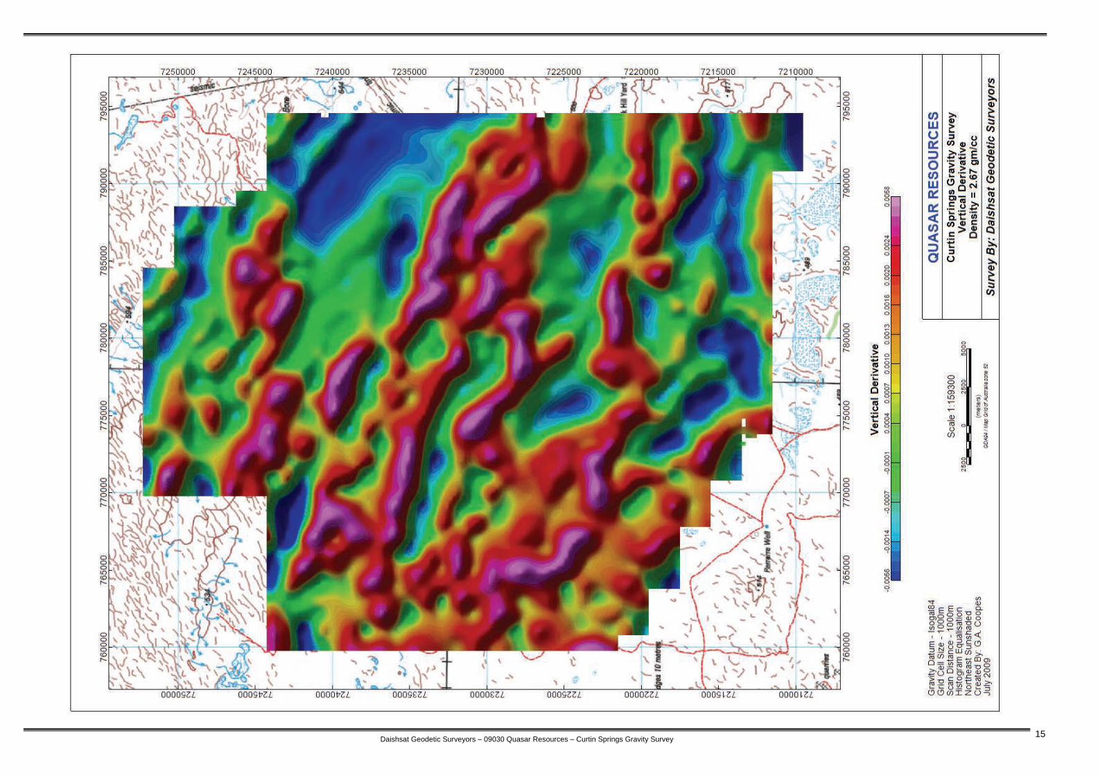
APPENDIX A Plots of station location / Images
Daishsat Geodetic Surveyors – 09030 Quasar Resources – Curtin Springs Gravity Survey 12

Daishsat Geodetic Surveyors – 09030 Quasar Resources – Curtin Springs Gravity Survey 13
Daishsat Geodetic Surveyors – 09030 Quasar Resources – Curtin Springs Gravity Survey 14
Daishsat Geodetic Surveyors – 09030 Quasar Resources – Curtin Springs Gravity Survey 15
Daishsat Geodetic Surveyors – 09030 Quasar Resources – Curtin Springs Gravity Survey 16
APPENDIX B Repeat Tabulation and Analysis
Histogram dAHD Histogram dOBSG84
Histogram dAHD
0
2
4
6
8
10
12
14
‐0.2
‐0.16
‐0.12
‐0.08
‐0.04
0 0.04
0.08
0.12
0.16
0.2
Difference Bin (m)
Freq
uency
Histogram dOBSG84
0
1
2
3
4
5
6
7
8
‐0.10
‐0.08
‐0.06
‐0.04
‐0.02
0.00
0.02
0.04
0.06
0.08
Difference Bin (mGal)
Freq
uency
Summary Statistics
Summary Table dAHD dOBSG Mean 0.002 -0.005 Standard Error 0.008 0.005 Median 0.014 -0.008 Mode 0.017 -0.008 Standard Deviation 0.062 0.036 Sample Variance 0.004 0.001 Kurtosis 0.198 0.981 Skewness -0.126 0.198 Range 0.286 0.194 Minimum -0.146 -0.085 Maximum 0.140 0.109 Sum 0.128 -0.315 Count 58 58
Daishsat Geodetic Surveyors – 09030 Quasar Resources – Curtin Springs Gravity Survey 17
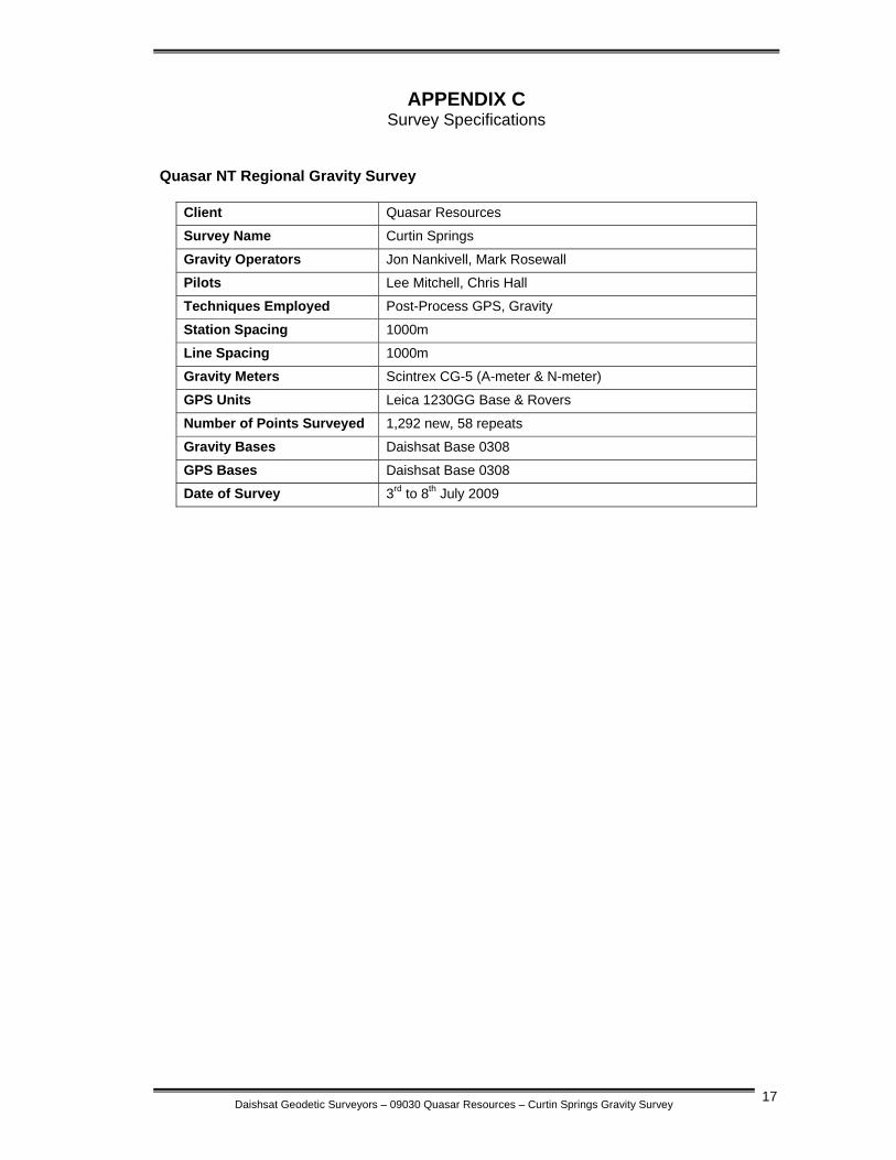
APPENDIX C Survey Specifications
Quasar NT Regional Gravity Survey
Client Quasar Resources
Survey Name Curtin Springs
Gravity Operators Jon Nankivell, Mark Rosewall
Pilots Lee Mitchell, Chris Hall
Techniques Employed Post-Process GPS, Gravity
Station Spacing 1000m
Line Spacing 1000m
Gravity Meters Scintrex CG-5 (A-meter & N-meter)
GPS Units Leica 1230GG Base & Rovers
Number of Points Surveyed 1,292 new, 58 repeats
Gravity Bases Daishsat Base 0308
GPS Bases Daishsat Base 0308
Date of Survey 3rd to 8th July 2009

Daishsat Geodetic Surveyors – 09030 Quasar Resources – Curtin Springs Gravity Survey 18
APPENDIX D Base Station Information
Daishsat Geodetic Surveyors – 09030 Quasar Resources – Curtin Springs Gravity Survey 19
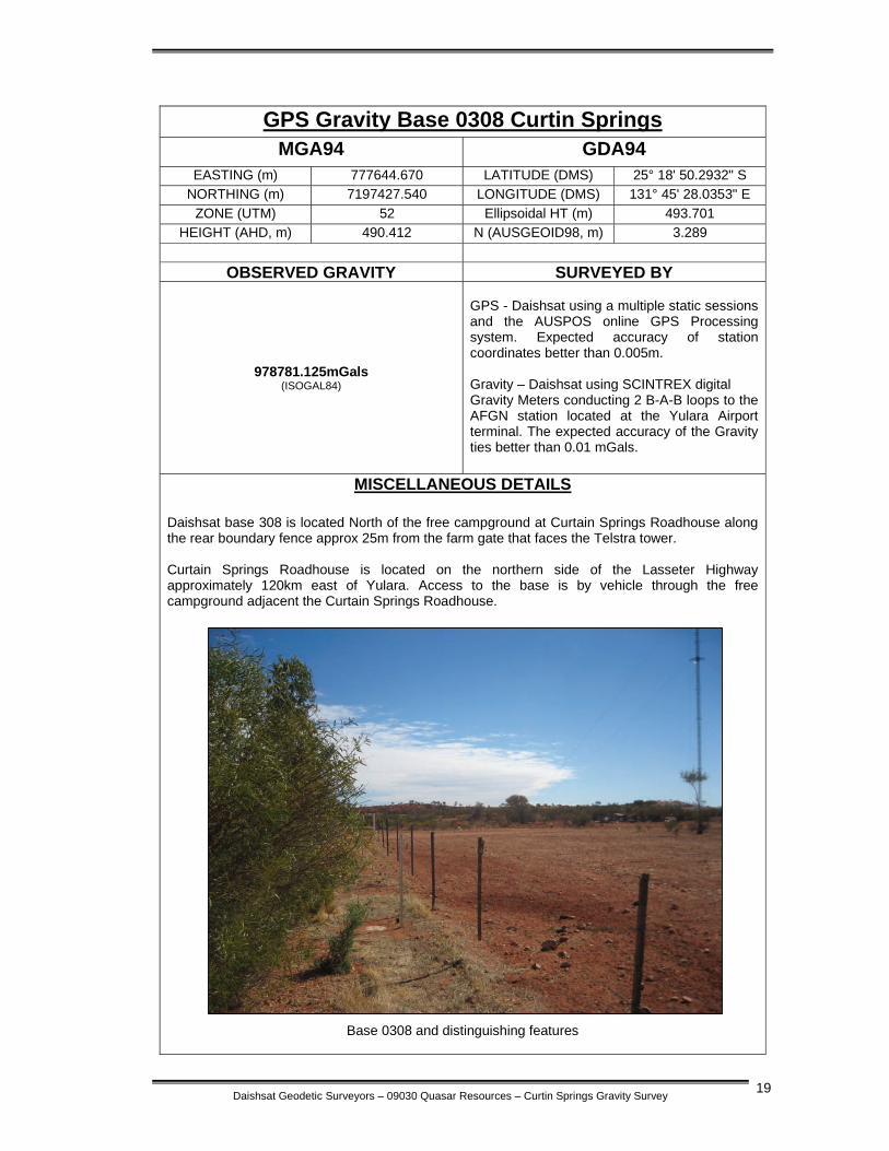
GPS Gravity Base 0308 Curtin Springs
MGA94 GDA94 EASTING (m) 777644.670 LATITUDE (DMS) 25° 18' 50.2932" S
NORTHING (m) 7197427.540 LONGITUDE (DMS) 131° 45' 28.0353" E ZONE (UTM) 52 Ellipsoidal HT (m) 493.701
HEIGHT (AHD, m) 490.412 N (AUSGEOID98, m) 3.289
OBSERVED GRAVITY SURVEYED BY
978781.125mGals (ISOGAL84)
GPS - Daishsat using a multiple static sessions and the AUSPOS online GPS Processing system. Expected accuracy of station coordinates better than 0.005m. Gravity – Daishsat using SCINTREX digital Gravity Meters conducting 2 B-A-B loops to the AFGN station located at the Yulara Airport terminal. The expected accuracy of the Gravity ties better than 0.01 mGals.
MISCELLANEOUS DETAILS Daishsat base 308 is located North of the free campground at Curtain Springs Roadhouse along the rear boundary fence approx 25m from the farm gate that faces the Telstra tower. Curtain Springs Roadhouse is located on the northern side of the Lasseter Highway approximately 120km east of Yulara. Access to the base is by vehicle through the free campground adjacent the Curtain Springs Roadhouse.
Base 0308 and distinguishing features

Daishsat Geodetic Surveyors – 09030 Quasar Resources – Curtin Springs Gravity Survey 20
APPENDIX E Data CD
(Attached To Back Cover)