Embed Size (px)
Citation preview

Quartus Counter Example
Common - last updated 9/6/18

2 © tjCommon
Quartus Counter Example
• Create a logic design from start to a DE10 implementation
• This example uses “best design practices”
• This example is not about creating HDL• The HDL code will be provided without explanation

3 © tjCommon
Quartus Counter Example
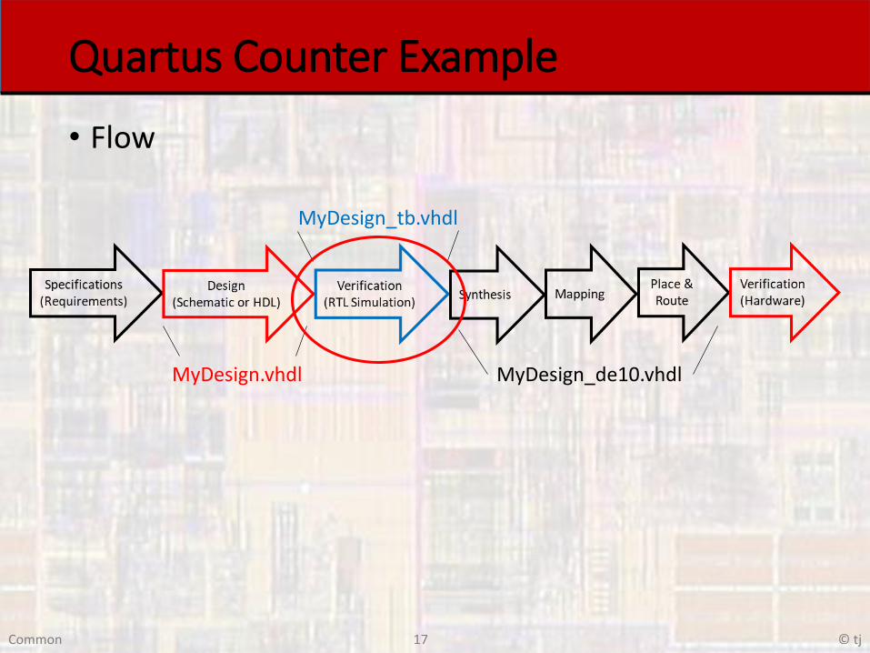
• Flow
MyDesign.vhdl
MyDesign_tb.vhdl
MyDesign_de10.vhdl

4 © tjCommon
Quartus Counter Example
• Flow
• Create project
• Create HDL code
• Verify RTL visually
• Create testbench
• Verify operation
• Create DE10 implementation HDL
• Compile
• Verify RTL visually
• Program DE10 board
• Verify operation manually

5 © tjCommon
Quartus Counter Example
• Flow
MyDesign.vhdl
MyDesign_tb.vhdl
MyDesign_de10.vhdl

6 © tjCommon
Quartus Counter Example
• Create a counter• Binary wrapping count
• N bits
• Up/down
• Test the design using ModelSim
• Implement an 8 bit version on the DE10• Reset and direction → switches
• Count value → LEDs
• Clock divider → 3Hz operation

7 © tjCommon
Quartus Counter Example
• Flow
MyDesign.vhdl
MyDesign_tb.vhdl
MyDesign_de10.vhdl

8 © tjCommon
Quartus Counter Example
• Create a new Project• Use the Quartus Project Setup notes as a guide• Switch to Files view mode
Note: the correctly namedSDC file is visible

9 © tjCommon
Quartus Counter Example
• Create a new HDL file• File → New → VHDL File

10 © tjCommon
Quartus Counter Example
• Create a new HDL file• Note – the default file name is Vhdl.vhd
• File → Save As and give it an informational file name
• Change the file extension to vhdl (for VHDL files)
• Make sure “Add file to current project” is checked
Note: New file is visible

11 © tjCommon
Quartus Counter Example
• Set the Top Level Entity• Right click on the design file in the Files window
• Select Set as Top Level Entity

12 © tjCommon
Quartus Counter Example
• Enter your design

13 © tjCommon
Quartus Counter Example
• Enter your design
------------------------------------------ Counter_updn_n_bit.vhdl---- created 6/22/18-- tj---- rev 0-------------------------------------------- n bit up/down counter example-- for showing a project from start to finish---------------------------------------------- Inputs: rstb, clk, dir-- Outputs: cnt---------------------------------------------- counts up when dir = 0-- counts down when dir = 1------------------------------------------
library ieee;use ieee.std_logic_1164.all;use ieee.numeric_std.all;
entity Counter_updn_n_bit isgeneric(
n: natural := 8);port (
i_clk: in std_logic; i_rstb: in std_logic;i_dir: in std_logic;
o_cnt : out std_logic_vector(n-1 downto 0));
end entity;
architecture behavioral of Counter_updn_n_bit is
---- internal signals--signal cnt_sig:unsigned(n-1 downto 0);
begin
process(i_clk, i_rstb)begin
---- reset--if (i_rstb = '0') then
cnt_sig <= (others => '0');---- rising clk edge--elsif (rising_edge(i_clk)) then
if(i_dir = '0') thencnt_sig <= cnt_sig + 1;
elsecnt_sig <= cnt_sig - 1;
end if;end if;
end process;
---- Output logic--o_cnt <= std_logic_vector(cnt_sig);
end behavioral;

14 © tjCommon
Quartus Counter Example
• Enter your design• Create a component template for your design (DUT)• Select File → Create/Update → Create VHDL Component
Declaration Files from Current File
Copyright (C) 2017 Intel Corporation. All rights reserved.-- Your use of Intel Corporation's design tools, logic functions -- and other software and tools, and its AMPP partner logic -- functions, and any output files from any of the foregoing -- (including device programming or simulation files), and any -- associated documentation or information are expressly subject -- to the terms and conditions of the Intel Program License -- Subscription Agreement, the Intel Quartus Prime License Agreement,-- the Intel FPGA IP License Agreement, or other applicable license-- agreement, including, without limitation, that your use is for-- the sole purpose of programming logic devices manufactured by-- Intel and sold by Intel or its authorized distributors. Please-- refer to the applicable agreement for further details.
-- Generated by Quartus Prime Version 17.1 (Build Build 590 10/25/2017)-- Created on Fri Feb 23 09:52:29 2018
COMPONENT Counter_updn_n_bitPORT(
i_rstb : IN STD_LOGIC;i_clk : IN STD_LOGIC;i_dir : IN STD_LOGIC;o_cnt : OUT STD_LOGIC_VECTOR(7 DOWNTO 0)
);END COMPONENT;

15 © tjCommon
Quartus Counter Example
• Elaborate• Check the design syntax and create RTL
• Processing → Start → Start Analysis and Elaboration
Fix all Errors
Review all Warnings
These warnings are due to the fact thatwe included the QSF file even thoughwe are not using this file for the DE10
16 © tjCommon
Quartus Counter Example
• Verify the RTL• Tools → Netlist Viewers → RTL Viewer
Counter Register
Up / Down SelectorUp - Adder
Down - Subtractor
b7 b6 b5 b4 b3 b2 b1 b0 ‘1’+ 1 1 1 1 1 1 1 0 1--------------------------------------Keep top 8 bitsEffectively adds -1
17 © tjCommon
Quartus Counter Example
• Flow
MyDesign.vhdl
MyDesign_tb.vhdl
MyDesign_de10.vhdl

18 © tjCommon
Quartus Counter Example
• Create Testbench• File → New → VHDL File
• File → Save As and give it an informational file name
Note: New file is visible

19 © tjCommon
Quartus Counter Example
• Enter your design

20 © tjCommon
Quartus Counter Example
• Enter your design---------------------------------- counter_updn_n_bit_tb.vhdl---- created: 3/17/18-- by: johnsontimoj-- rev: 0---- testbench for up down counter-- of counter_updn_n_bit.vhdl---------------------------------library ieee;use ieee.std_logic_1164.all;
entity counter_updn_n_bit_tb isgeneric(
N: natural := 8);-- no port entry - testbench
end entity;
architecture testbench of counter_updn_n_bit_tb issignal CLK: std_logic;signal RSTB: std_logic;signal DIR: std_logic;
signal CNT: std_logic_vector((N - 1) downto 0);
constant PER: time := 20 ns;
---------------------------------- Component prototype---------------------------------component counter_updn_n_bit
generic ( n : NATURAL := 8 );port(
i_rstb : IN STD_LOGIC;i_clk : IN STD_LOGIC;i_dir : IN STD_LOGIC;o_cnt : OUT STD_LOGIC_VECTOR((n - 1) downto
0));
end component;-----------------------------------
begin
-------------------------------------- Device under test (DUT)------------------------------------DUT: counter_updn_n_bit
generic map(n => N)
port map(i_clk => CLK,i_rstb => RSTB,i_dir => DIR,o_cnt => CNT);
--------------------------------------- Test processes-------------------------------------
-- Clock processclock: processbegin
CLK <= '0';wait for PER/2;infinite: loop
CLK <= not CLK; wait for PER/2;end loop;
end process;
-- Reset processreset: processbegin
RSTB <= '0'; wait for 2*PER;RSTB <= '1'; wait;
end process reset;
-- Run Processrun: processbegin
-- initialize inputsDIR <= '0';
-- wait for resetwait for 2*PER;
-- run codewait for (2**N)*PER;DIR <= '1';wait;
end process run;-------------------------------------------- End test processes------------------------------------------
end architecture;

21 © tjCommon
Quartus Counter Example
• Enter your design• Elaborate the design • With the original vhdl design set as the top level entity (not the
xxxx_tb.vhdl design)
• Select Processing → Start → Start Analysis and Elaboration
• This causes Quartus to check the Test Bench code along with the original vhdl design

22 © tjCommon
Quartus Counter Example
• Setup your simulation• Use the ModelSim Testbench Setup notes as a guide
23 © tjCommon
Quartus Counter Example
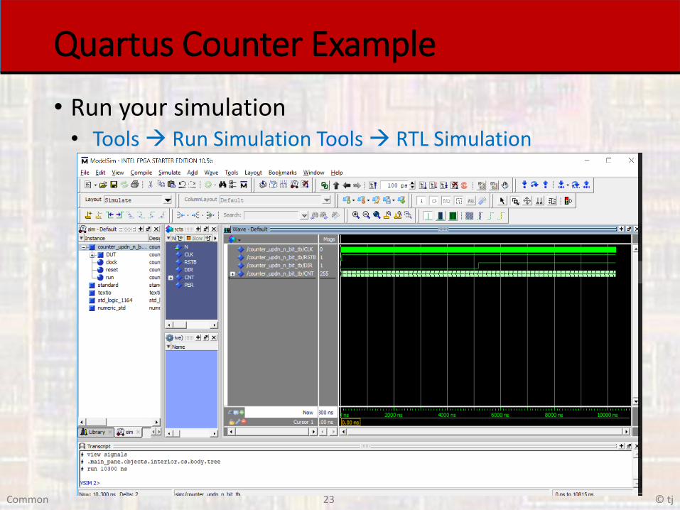
• Run your simulation• Tools → Run Simulation Tools → RTL Simulation

24 © tjCommon
Quartus Counter Example
• Verify your design
Reset &Count up
Wrap up &Count down
Wrap down

25 © tjCommon
Quartus Counter Example
• Flow
MyDesign.vhdl
MyDesign_tb.vhdl
MyDesign_de10.vhdl
26 © tjCommon
Quartus Counter Example
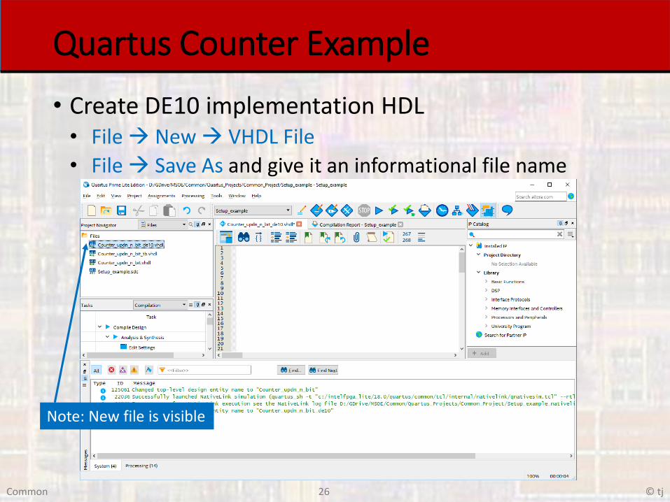
• Create DE10 implementation HDL• File → New → VHDL File
• File → Save As and give it an informational file name
Note: New file is visible

27 © tjCommon
Quartus Counter Example
• Set the Top Level Entity• Right click on the design file in the Files window
• Select Set as Top Level Entity

28 © tjCommon
Quartus Counter Example
• Enter your design

29 © tjCommon
Quartus Counter Example
• Enter your design---------------------------------- counter_updn_n_bit_de10.vhdl---- created: 3/17/18-- by: johnsontimoj-- rev: 0---- DE10 implementation for up down counter-- of counter_updn_n_bit.vhdl---- Uses a 3 Hz clock divider, sw0 for reset-- sw1 for the dir input-- and LEDs for the count output-------------------------------library ieee;use ieee.std_logic_1164.all;
entity counter_updn_n_bit_de10 isport(
CLOCK_50: in std_logic;SW: in std_logic_vector(1 downto 0);
LEDR: out std_logic_vector(7 downto 0));
end entity;
architecture hardware of counter_updn_n_bit_de10 is
signal CLK_SIG: std_logic; -- Intermediate clk signal
---------------------------------- Component prototypes---------------------------------component clk_3Hz
port(i_clk_50MHz : IN STD_LOGIC;i_rstb : IN STD_LOGIC;o_clk_3Hz : OUT STD_LOGIC
);end component;
component counter_updn_n_bitgeneric ( n : NATURAL := 8 );port(
i_rstb : IN STD_LOGIC;i_clk : IN STD_LOGIC;i_dir : IN STD_LOGIC;o_cnt : OUT STD_LOGIC_VECTOR((n - 1) downto 0)
);end component;
begin
-- Device under test (DUT)------------------------------------CK: clk_3Hz
port map(i_clk_50MHz => CLOCK_50,i_rstb => SW(0),o_clk_3Hz => CLK_SIG
);
DUT: counter_updn_n_bitport map(
i_clk => CLK_SIG,i_rstb => SW(0),i_dir => SW(1),o_cnt => LEDR(7 downto 0)
);
end architecture;

30 © tjCommon
Quartus Counter Example
• Create a clock divider• File → New → VHDL File
• File → Save As and give it an informational file name
Note: New file is visible

31 © tjCommon
Quartus Counter Example
• Enter your design

32 © tjCommon
Quartus Counter Example
• Enter your design------------------------------------------ clk_3Hz.vhdl---- created 2/29/17-- tj---- rev 0-------------------------------------------- 50MHz -> 3Hz clock divider HDL---------------------------------------------- Inputs: rstb, clk_50MHz-- Outputs: clk_3Hz---------------------------------------------- Notes:---- Typically this will be instantiated in a top level HDL for -- implementation on the DE10 board---- The 50 MHz clock input would be tied to CLOCK_50-- the output clock would be tied to the clock inputs of the-- remainder of the design--library ieee;use ieee.std_logic_1164.all;use ieee.numeric_std.all;
entity clk_3Hz isport (
i_clk_50MHz : in std_logic; i_rstb : in std_logic;
o_clk_3Hz : out std_logic);
end entity;
architecture behavioral of clk_3Hz is--
-- constants and parameters --constant Tover2: signed(24 downto 0) := to_signed(8_333_332, 25);
---- internal signals--signal cnt: signed(24 downto 0);signal clk_out: std_logic;
begin process(i_clk_50MHz, i_rstb)begin
---- reset--if (i_rstb = '0') then
cnt <= Tover2;clk_out <= '0';
---- rising clk edge--elsif (rising_edge(i_clk_50MHz)) then
cnt <= cnt - 1;--
-- check if half way--if (cnt < 0) then
cnt <= Tover2;clk_out <= not clk_out;
end if;end if;
end process;
---- Output logic--o_clk_3Hz <= clk_out;
end behavioral;

33 © tjCommon
Quartus Counter Example
• Compile• Check the design syntax, create RTL, Place and Route
• Processing → Start Compilation
Fix all Errors
Review all Warnings
Check for timing issues

34 © tjCommon
Quartus Counter Example
• Compile• Check the Flow Summary
Check to make sureutilization makes sense
Check success
Correct Top Level Design
Correct Part Number

35 © tjCommon
Quartus Counter Example
• Verify the RTL• Tools → Netlist Viewers → RTL Viewer
Counter
Correct I/O
Clock divider

36 © tjCommon
Quartus Counter Example
• Flow
MyDesign.vhdl
MyDesign_tb.vhdl
MyDesign_de10.vhdl

37 © tjCommon
Quartus Counter Example
• Program the board• Connect the DE10 board to computer
• Tools → Programmer• Point to the compiled output file xxxx.sof
• Start
38 © tjCommon
Quartus Counter Example
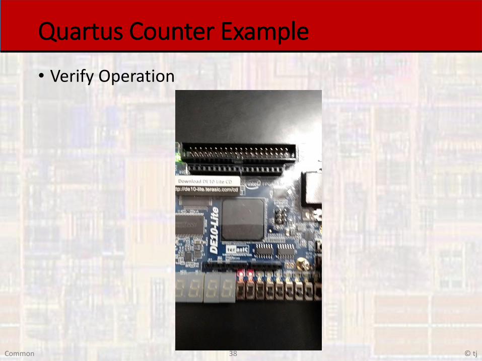
• Verify Operation