Embed Size (px)
Citation preview
COE-758 Quartus II Beginner Tutorial
1. Start Quartus II by typing >quartus in your terminal window.
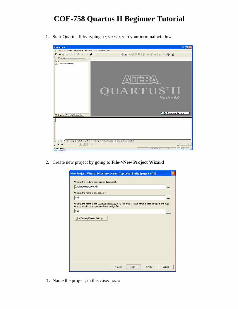
2. Create new project by going to File->New Project Wizard
3. Name the project, in this case: mux
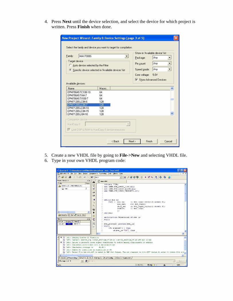
4. Press Next until the device selection, and select the device for which project is
written. Press Finish when done.
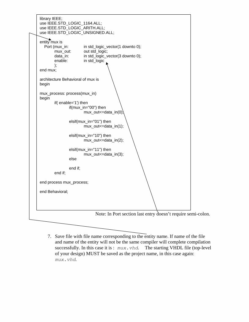
5. Create a new VHDL file by going to File->New and selecting VHDL file. 6. Type in your own VHDL program code:
Note: In Port section last entry doesn’t require semi-colon.
7. Save file with file name corresponding to the entity name. If name of the file and name of the entity will not be the same compiler will complete compilation successfully. In this case it is : mux.vhd. The starting VHDL file (top-level of your design) MUST be saved as the project name, in this case again: mux.vhd.
library IEEE; use IEEE.STD_LOGIC_1164.ALL; use IEEE.STD_LOGIC_ARITH.ALL; use IEEE.STD_LOGIC_UNSIGNED.ALL; entity mux is Port (mux_in: in std_logic_vector(1 downto 0); mux_out: out std_logic; data_in: in std_logic_vector(3 downto 0); enable: in std_logic ); end mux; architecture Behavioral of mux is begin mux_process: process(mux_in) begin if( enable='1') then if(mux_in="00") then mux_out<=data_in(0); elsif(mux_in="01") then mux_out<=data_in(1); elsif(mux_in="10") then mux_out<=data_in(2); elsif(mux_in="11") then mux_out<=data_in(3); else end if; end if; end process mux_process; end Behavioral;
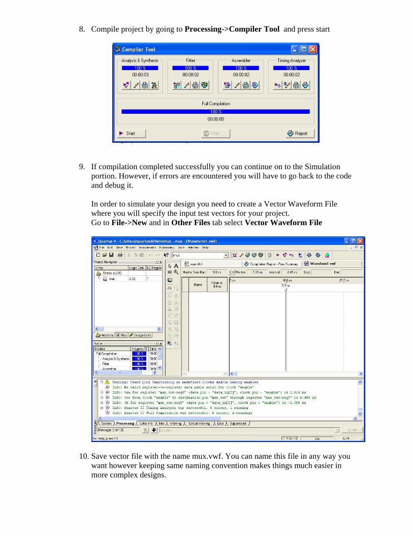
8. Compile project by going to Processing->Compiler Tool and press start
9. If compilation completed successfully you can continue on to the Simulation portion. However, if errors are encountered you will have to go back to the code and debug it. In order to simulate your design you need to create a Vector Waveform File where you will specify the input test vectors for your project. Go to File->New and in Other Files tab select Vector Waveform File
10. Save vector file with the name mux.vwf. You can name this file in any way you want however keeping same naming convention makes things much easier in more complex designs.
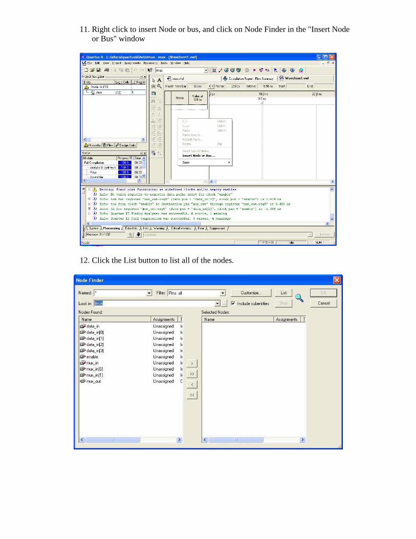
11. Right click to insert Node or bus, and click on Node Finder in the "Insert Node or Bus" window
12. Click the List button to list all of the nodes.
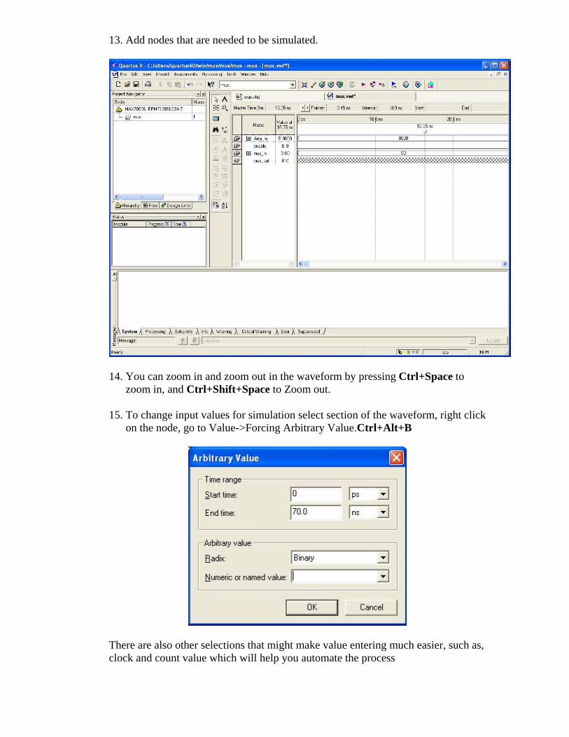
13. Add nodes that are needed to be simulated.
14. You can zoom in and zoom out in the waveform by pressing Ctrl+Space to
zoom in, and Ctrl+Shift+Space to Zoom out.
15. To change input values for simulation select section of the waveform, right click on the node, go to Value->Forcing Arbitrary Value.Ctrl+Alt+B
There are also other selections that might make value entering much easier, such as, clock and count value which will help you automate the process
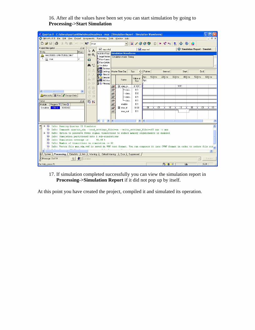
16. After all the values have been set you can start simulation by going to Processing->Start Simulation
17. If simulation completed successfully you can view the simulation report in
Processing->Simulation Report if it did not pop up by itself. At this point you have created the project, compiled it and simulated its operation.