Embed Size (px)
Citation preview
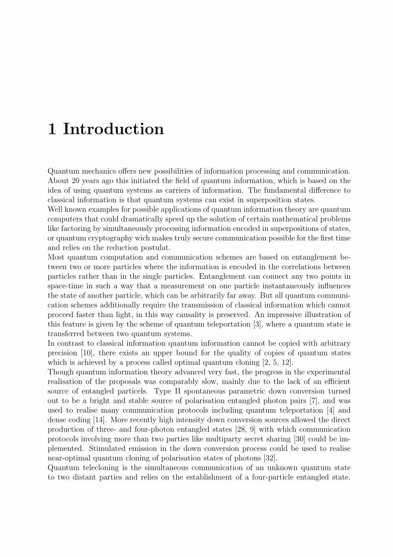
Quantum Telecloning
Diplomarbeit an der Fakultat fur Physik
der
Ludwig-Maximilians-Universitat Munchen
Arbeitsgruppe Prof. Dr. Harald Weinfurter
Julia Lau
16. Februar 2004
Erstgutachter: Prof. Dr. Harald Weinfurter
Zweitgutachter: Prof. Dr. Hans J. Briegel


Contents
1 Introduction 3
2 Theory 52.1 Polarised light . . . . . . . . . . . . . . . . . . . . . . . . . . . . . . . . . . 52.2 Qubits . . . . . . . . . . . . . . . . . . . . . . . . . . . . . . . . . . . . . . 62.3 Entanglement . . . . . . . . . . . . . . . . . . . . . . . . . . . . . . . . . . 72.4 Quantum teleportation . . . . . . . . . . . . . . . . . . . . . . . . . . . . . 82.5 Quantum cloning . . . . . . . . . . . . . . . . . . . . . . . . . . . . . . . . 10
2.5.1 No-cloning theorem . . . . . . . . . . . . . . . . . . . . . . . . . . . 102.5.2 Optimal quantum cloning . . . . . . . . . . . . . . . . . . . . . . . 112.5.3 The ’classical’ limit . . . . . . . . . . . . . . . . . . . . . . . . . . . 12
2.6 Quantum telecloning . . . . . . . . . . . . . . . . . . . . . . . . . . . . . . 13
3 Implementation 193.1 Parametric down conversion . . . . . . . . . . . . . . . . . . . . . . . . . . 193.2 Bell state analysis . . . . . . . . . . . . . . . . . . . . . . . . . . . . . . . . 22
3.2.1 Influences of beam splitter parameters on the Bell state analysis . . 243.2.2 Hong Ou Mandel dip . . . . . . . . . . . . . . . . . . . . . . . . . . 28
3.3 Measurement of density matrices . . . . . . . . . . . . . . . . . . . . . . . 32
4 Experiment 354.1 The setup . . . . . . . . . . . . . . . . . . . . . . . . . . . . . . . . . . . . 35
4.1.1 The source of entangled photons . . . . . . . . . . . . . . . . . . . . 364.1.2 Weak coherent state preparation . . . . . . . . . . . . . . . . . . . . 424.1.3 The analysers . . . . . . . . . . . . . . . . . . . . . . . . . . . . . . 43
4.2 The overlap . . . . . . . . . . . . . . . . . . . . . . . . . . . . . . . . . . . 454.2.1 Classical interference . . . . . . . . . . . . . . . . . . . . . . . . . . 454.2.2 Interference between two down conversion photons . . . . . . . . . 464.2.3 Interference between a down conversion photon and a weak coherent
state . . . . . . . . . . . . . . . . . . . . . . . . . . . . . . . . . . . 494.3 Quantum teleportation . . . . . . . . . . . . . . . . . . . . . . . . . . . . . 534.4 Quantum telecloning . . . . . . . . . . . . . . . . . . . . . . . . . . . . . . 55
4.4.1 Telecloning of three different input states . . . . . . . . . . . . . . . 56

CONTENTS
4.4.2 Measurement of the density matrices of the clones . . . . . . . . . . 59
5 Summary 63
A Appendix 65A.1 Determination of beam splitter parameters . . . . . . . . . . . . . . . . . . 65A.2 Representations of photon states . . . . . . . . . . . . . . . . . . . . . . . . 67
2
1 Introduction
Quantum mechanics offers new possibilities of information processing and communication.About 20 years ago this initiated the field of quantum information, which is based on theidea of using quantum systems as carriers of information. The fundamental difference toclassical information is that quantum systems can exist in superposition states.Well known examples for possible applications of quantum information theory are quantumcomputers that could dramatically speed up the solution of certain mathematical problemslike factoring by simultaneously processing information encoded in superpositions of states,or quantum cryptography wich makes truly secure communication possible for the first timeand relies on the reduction postulat.Most quantum computation and communication schemes are based on entanglement be-tween two or more particles where the information is encoded in the correlations betweenparticles rather than in the single particles. Entanglement can connect any two points inspace-time in such a way that a measurement on one particle instantaneously influencesthe state of another particle, which can be arbitrarily far away. But all quantum communi-cation schemes additionally require the transmission of classical information which cannotproceed faster than light, in this way causality is preserved. An impressive illustration ofthis feature is given by the scheme of quantum teleportation [3], where a quantum state istransferred between two quantum systems.In contrast to classical information quantum information cannot be copied with arbitraryprecision [10], there exists an upper bound for the quality of copies of quantum stateswhich is achieved by a process called optimal quantum cloning [2, 5, 12].Though quantum information theory advanced very fast, the progress in the experimentalrealisation of the proposals was comparably slow, mainly due to the lack of an efficientsource of entangled particels. Type II spontaneous parametric down conversion turnedout to be a bright and stable source of polarisation entangled photon pairs [7], and wasused to realise many communication protocols including quantum teleportation [4] anddense coding [14]. More recently high intensity down conversion sources allowed the directproduction of three- and four-photon entangled states [28, 9] with which communicationprotocols involving more than two parties like multiparty secret sharing [30] could be im-plemented. Stimulated emission in the down conversion process could be used to realisenear-optimal quantum cloning of polarisation states of photons [32].Quantum telecloning is the simultaneous communication of an unknown quantum stateto two distant parties and relies on the establishment of a four-particle entangled state.
1 Introduction
It represents a combination of quantum teleportation and optimal quantum cloning, sincequantum information is copied and transmitted in a single step.The goal of this diploma thesis was the experimental implementation of quantum tele-cloning using a four-photon polarisation entangled state, which is obtained directly fromparametric down conversion. The state to be telecloned was encoded in the polarisation ofa strongly attenuated laser beam approximating single photons.The experiment posed a challenge in two different respects. On the one hand the detectionof a five-photon state was required, which was at the border of feasibilty due to extremelylow countrates and high background contributions and therefore had no example. On theother hand two photons from independent sources (one from the weak coherent beam andone from down conversion) had to be projected onto the Bell state basis. The establish-ment and optimisation of the necessary quantum interference was one of the main tasks ofmy work during this year.As a preliminary study a teleportation experiment was planned which required the sameexperimental setup but shorter measurement times.The experiment has been performed together with two PhD students, Sascha Gaertner,who had also planned and prepared the experiment, and Nikolai Kiesel, who joined us lateron and is now taking over the experimental work.The thesis is organised as follows. Chapter 2 provides the theoretical basis for the exper-iment. It is shown how qubits, the basic unit of quantum information, can be encodedin polarisation states of photons, and a definition of entanglement is given. It follows thetheory of quantum teleportation, optimal quantum cloning and quantum telecloning. Inchapter 3 different techniques necessary for the implementation of the scheme are pre-sented: the process of parametric down conversion with which polarisation entangled two-and four-photon states were generated, interferometric Bell state analysis, and a methodfor the measurement of density matrices of qubits, which was used for an analysis of theoutput states. Finally in chapter 4 the experimental procedures and results are presented.
4

2 Theory
In this chapter the theoretical basis for the experiment is provided. It starts with a de-scription of the different forms of polarisation of light in section 2.1. The polarisation of alight wave is oriented perpendicular to the propagation direction and therefore can alwaysbe decomposed in two orthogonal polarisation components. Hence the polarisation stateof a single photon is a two level quantum system which can be used to encode qubits, thebasic unit of quantum information, as described in section 2.2.Like many quantum communication schemes quantum telecloning relies on entanglementbetween qubits, which is introduced in section 2.3. Since quantum telecloning representsa combination of quantum teleportation and optimal quantum cloning [1], chapters 2.4and 2.5 deal with those two subjects. Quantum teleportation is the transmission and re-construction of an unknown quantum state over arbitrary distances [3, 4], and optimalquantum cloning is the most faithful way to copy quantum information [11, 5, 2], sinceperfect copying is forbidden by the no-cloning theorem [10]. In the process of quantumtelecloning two optimal clones of an unknown quantum state are transferred to two distantreceivers. The scheme is presented in section 2.6.
2.1 Polarised light
A light wave can be described as an oszillating electromagnetic field. It is called polarisedif the field directions are periodic functions of time and space as opposed to unpolarisedlight where these directions vary randomly [25]. Because the magnetic field is alwaysoriented perpendicularly to the electric field one usually consideres only the electric field.For polarised light propagating along the z axis the electric field can always be decomposedin a field in x direction and a field in y direction:
~Ex(z, t) = Ex~ex sin(ωt− kz + φ1)
~Ey(z, t) = Ey~ey sin(ωt− kz + φ2)
If both components are in phase the light is called linearly polarised:
~E(z, t) = (Ex~ex + Ey~ey) sin(ωt− kz + φ0)
If they have the same magnitude but a relative phase shift of π/2 the light is called left orright circularly polarised:
2 Theory
Right circular polarisation (rcp):
~Ercp(z, t) = E(sin(ωt− kz + φ0)~ex + cos(ωt− kz + φ0)~ey)
Left circular polarisation (lcp):
~Elcp(z, t) = E(sin(ωt− kz + φ0)~ex − cos(ωt− kz + φ0)~ey)
For all other combinations of ~Ex and ~Ey the light is called elliptically polarised. Instead
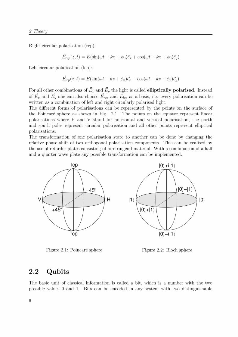
of ~Ex and ~Ey one can also choose ~Ercp and ~Elcp as a basis, i.e. every polarisation can bewritten as a combination of left and right circularly polarised light.The different forms of polarisations can be represented by the points on the surface ofthe Poincare sphere as shown in Fig. 2.1. The points on the equator represent linearpolarisations where H and V stand for horizontal and vertical polarisation, the northand south poles represent circular polarisation and all other points represent ellipticalpolarisations.The transformation of one polarisation state to another can be done by changing therelative phase shift of two orthogonal polarisation components. This can be realised bythe use of retarder plates consisting of birefringend material. With a combination of a halfand a quarter wave plate any possible transformation can be implemented.
V H
lcp
−45
rcp
0+45
0
Figure 2.1: Poincare sphere
/\|0
\ −|0 / \/
\/
/\
\/
\/|1
|1
\|0 / + |1
|0 /\ +i |1
|0 /\ −i |1
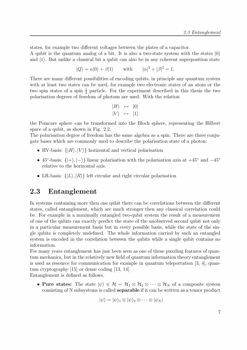
Figure 2.2: Bloch sphere
2.2 Qubits
The basic unit of classical information is called a bit, which is a number with the twopossible values 0 and 1. Bits can be encoded in any system with two distinguishable
6
2.3 Entanglement
states, for example two different voltages between the plates of a capacitor.A qubit is the quantum analog of a bit. It is also a two-state system with the states |0〉and |1〉. But unlike a classical bit a qubit can also be in any coherent superposition state
|Q〉 = α|0〉+ β|1〉 with |α|2 + |β|2 = 1.
There are many different possibilities of encoding qubits, in principle any quantum systemwith at least two states can be used, for example two electronic states of an atom or thetwo spin states of a spin 1
2particle. For the experiment described in this thesis the two
polarisation degrees of freedom of photons are used. With the relation
|H〉 ↔ |0〉|V 〉 ↔ |1〉
the Poincare sphere can be transformed into the Bloch sphere, representing the Hilbertspace of a qubit, as shown in Fig. 2.2.The polarisation degree of freedom has the same algebra as a spin. There are three conju-gate bases which are commonly used to describe the polarisation state of a photon:
• HV-basis: {|H〉, |V 〉} horizontal and vertical polarisation
• 45◦-basis: {|+〉, |−〉} linear polarisation with the polarisation axis at +45◦ and −45◦
relative to the horizontal axis.
• LR-basis: {|L〉, |R〉} left circular and right circular polarisation
2.3 Entanglement
In systems containing more then one qubit there can be correlations between the differentstates, called entanglement, which are much stronger then any classical correlation couldbe. For example in a maximally entangled two-qubit system the result of a measurementof one of the qubits can exactly predict the state of the unobserved second qubit not onlyin a particular measurement basis but in every possible basis, while the state of the sin-gle qubits is completely undefined. The whole information carried by such an entangledsystem is encoded in the correlation between the qubits while a single qubit contains noinformation.For many years entanglement has just been seen as one of those puzzling features of quan-tum mechanics, but in the relatively new field of quantum information theory entanglementis used as resource for communication for example in quantum teleportation [3, 4], quan-tum cryptography [15] or dense coding [13, 14].Entanglement is defined as follows.
• Pure states: The state |ψ〉 ∈ H = H1 ⊗ H2 ⊗ · · · ⊗ HN of a composite systemconsisting of N subsystems is called separable if it can be written as a tensor product
|ψ〉 = |ψ〉1 ⊗ |ψ〉2 ⊗ · · · ⊗ |ψN〉
7
2 Theory
with |ψ〉1 ∈ H1, |ψ〉2 ∈ H2, · · · , |ψ〉N ∈ HN .
If this is not possible the state is called entangled.
• Mixed states: The state ρ ∈ B(H) = B(H1) ⊗ B(H2) ⊗ · · · ⊗ B(HN) is calledseparable if it can be written in the form
ρ =∑
k
pk|1k〉〈1k| ⊗ |2k〉〈2k| ⊗ · · · ⊗ |Nk〉〈Nk|
with |1k〉 ∈ H1, |2k〉 ∈ HB, . . . , |Nk〉 ∈ HN
and where B(H) is the space of bounded operators acting on H.Otherwise the state is called entangled.
The best known example for entangled states in the case of two qubit systems are the Bellstates:
|φ+〉 =1√2
(|HH〉+ |V V 〉)
|φ−〉 =1√2
(|HH〉 − |V V 〉)
|ψ+〉 =1√2
(|HV 〉+ |V H〉)
|ψ−〉 =1√2
(|HV 〉 − |V H〉)
They form an orthonormal basis of the two qubit Hilbertspace and they are maximallyentangled, which means that the reduced density matrices of the single qubit states (whichare obtained by tracing over the state of the second qubit) are maximally mixed.
2.4 Quantum teleportation
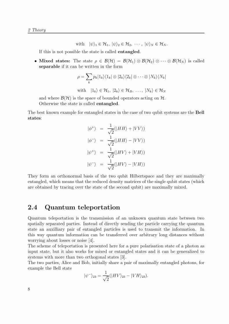
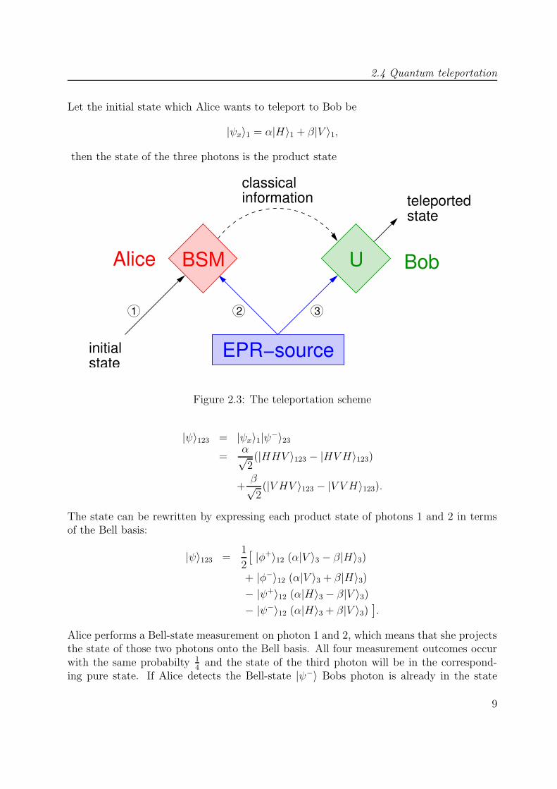
Quantum teleportation is the transmission of an unknown quantum state between twospatially separated parties. Instead of directly sending the particle carrying the quantumstate an auxilliary pair of entangled particles is used to transmit the information. Inthis way quantum information can be transferred over arbitrary long distances withoutworrying about losses or noise [4].The scheme of teleportation is presented here for a pure polarisation state of a photon asinput state, but it also works for mixed or entangled states and it can be generalized tosystems with more than two orthogonal states [3].The two parties, Alice and Bob, initially share a pair of maximally entangled photons, forexample the Bell state
|ψ−〉23 =1√2
(|HV 〉23 − |V H〉23).
8
2.4 Quantum teleportation
Let the initial state which Alice wants to teleport to Bob be
|ψx〉1 = α|H〉1 + β|V 〉1,
then the state of the three photons is the product state
teleportedstate
initialstate
classicalinformation
BSM U
321
EPR−source
BobAlice
Figure 2.3: The teleportation scheme
|ψ〉123 = |ψx〉1|ψ−〉23
=α√2
(|HHV 〉123 − |HVH〉123)
+β√2
(|V HV 〉123 − |V V H〉123).
The state can be rewritten by expressing each product state of photons 1 and 2 in termsof the Bell basis:
|ψ〉123 =1
2
[|φ+〉12 (α|V 〉3 − β|H〉3)
+ |φ−〉12 (α|V 〉3 + β|H〉3)− |ψ+〉12 (α|H〉3 − β|V 〉3)
− |ψ−〉12 (α|H〉3 + β|V 〉3)].
Alice performs a Bell-state measurement on photon 1 and 2, which means that she projectsthe state of those two photons onto the Bell basis. All four measurement outcomes occurwith the same probabilty 1
4and the state of the third photon will be in the correspond-
ing pure state. If Alice detects the Bell-state |ψ−〉 Bobs photon is already in the state
9
2 Theory
|ψx〉 which Alice sought to teleport. In all other cases the state of Bobs photon can betransformed unitarily into the initial state:
−σzσx(α|V 〉3 − β|H〉3) = |ψx〉σx(α|V 〉3 + β|H〉3) = |ψx〉σz(α|H〉3 − β|V 〉3) = |ψx〉
with the Pauli matrices
σx =
(0 11 0
)and σz =
(1 00 −1
).
If Alice sends the result of her Bell-state measurement to Bob by means of classical commu-nication, Bob can apply the corresponding unitary transformation in order to convert thestate of his photon into Alice’s original state. Whereas photon 1, which was initially in thetransferred state, has been projected together with photon 2 onto a maximally entangledstate and is therefore in a completely mixed state which doesn’t contain any informationabout the original state.It is interesting to mention that the teleported quantum information has been split intotwo parts during the transmission: a purely nonclassical part which is transferred instan-taneously via the entanglement between photon 2 and 3, and a purely classical part, theoutcome of the Bell-state measurement which is simply a number between 0 and 3 andtherefore equals two bit of classical information. The quantum information alone wouldbe of no use, because without the correct unitary transformation the state of photon 3is in a mixed state which has no correlations with the initial state. Thus the completeteleportation cannot proceed faster than light as required by the principle of causality.
2.5 Quantum cloning
Unlike classical information quantum information cannot be copied with arbitrary preci-sion, this is the message of the no-cloning theorem [10]. There exists an upper bound forthe quality of the copies of an arbitrary unknown quantum state which can be reached by aprocess called optimal quantum cloning [2]. Even if these quantum clones are not perfect,it is imposible to achieve the same quality by just doing a measurement on the input state,which is the usual method to copy classical information.
2.5.1 No-cloning theorem
The no-cloning theorem states that it is impossible to create a perfect copy of an arbitraryunknown quantum state while preserving the original quantum state. For example inquantum teleportation the input state can be recreated perfectly, but just at the expenseof the complete destruction of the original state.The assumption of the existence of such a perfect cloning machine leads to a contradiction
10
2.5 Quantum cloning
with the linearity of quantum mechanics: Such a machine should produce perfect copiesof every quantum state |ψ〉:
|ψ〉|0〉 CM−→ |ψ〉|ψ〉,for example |H〉 and |V 〉
|H〉|0〉 CM−→ |H〉|H〉|V 〉|0〉 CM−→ |V 〉|V 〉.
The linearity of quantum mechanics implies then:
(|H〉+ |V 〉)|0〉 QM−→ |H〉|H〉+ |V 〉|V 〉,which is not equivalent to the output of an ideal cloning machine:
(|H〉+ |V 〉)|0〉 CM−→ (|H〉+ |V 〉)(|H〉+ |V 〉)= |H〉|H〉+ |H〉|V 〉+ |V 〉|H〉+ |V 〉|V 〉.
The no-cloning theorem is one of the most fundamental differences between quantum andclassical information theory. For example for a quantum computer it would be impossibleto copy data, which is quite a basic task for a classical computer. On the other hand thistheorem is the reason for the security of quantum cryptography. Quantum cryptographyis based on the fact that it is impossible for an eavesdropper to read the transferred datawithout disturbing it. If perfect cloning would be possible, an eavesdropper could justcreate two copies of each qubit, keep one of them and send the other one to the receiverwho would have no possibility to find out about the eavesdropping.
2.5.2 Optimal quantum cloning
Perfect cloning is impossible according to the no-cloning theorem, but it is interesting toask how accurately such copies can be made. As a measurement for the quality of thecopies the fidelity F is used. It is defined as the mean overlap beween a copy and theinput state:
F := 〈ψx|ρc|ψx〉where |ψx〉 is the input state and ρc is the density matrix of one of the copies. The fidelityis a number between 0 and 1, 1 for a perfect copy ρc = |ψx〉〈ψx| and 0 if the output stateis orthogonal to the input state.The process of cloning quantum states can be described by a quantum cloning machine[2] which transforms N identical qubits into M > N identical copies. The initial state,consisting of N input qubits, M − N so called blank paper qubits and an ancilla, istransformed unitarily into the state of M clones and the ancilla. It can be shown [2] thatthe maximal fidelity of the clones achievable in such a process is
FN,M =M(N + 1) +N
M(N + 2). (2.1)
11

2 Theory
>| Φ Φ| >’
>0|
Ψ >|Ψ| >’
Transformation
Unitary
......
......
......
M−N
......
......
...
N
M
Figure 2.4: Quantum cloning machine
If the quality of the copies is dependent on the input state it is possible to reach higherfidelities for some particular input states. For example the copying machine considered inthe proof of the no-cloning theorem works perfectly for the input states |H〉 and |V 〉 butcreates poor copies of some superpositions of |H〉 and |V 〉. If this maximal fidelity (Eq.(2.1)) is reached for all kinds of input states then the process is called optimal universalquantum cloning.The more input states there are the more information is given about them, in the case ofa quasiclassical input state with N →∞ and M = N + 1 the fidelity tends towards 1. Onthe other hand the fidelity of the copies decreases if their number M grows, correspondingto the fact that the information is spread among a bigger number of parties.For the telecloning experiment described in this thesis two copies of a single qubit havebeen made, so the optimal fidelity in this case would be
F1,2 =5
6≈ 83, 3%.
2.5.3 The ’classical’ limit
The quantum cloning machine can be compared with a simpler copying process which iscalled the classical copying machine. It consists in a measurement on the N identical
Ψ| >’
Ψ >|
Ψ >|
Ψ| >’
Ψ| >’
with outcomeMeasurement
N
......
......
......
....
......
......
......
....
M
Figure 2.5: Classical copying machine
input states and the result of the measurement is used to make an arbitrary number M ofcopies. It can be shown [18] that in this case the maximal (average) fidelity, which is often
12
2.6 Quantum telecloning
refered to as the classical limit, is
FN =N + 1
N + 2.
It is of course independent of the number of copies which are made, and it also tendstowards 1 for a quasiclassical input state with N →∞.This maximum fidelity can be reached by so called optimal measurements where the inputqubits are not measured separately but as a single composite system [18]. In the case ofa single qubit an optimal measurement is just a projection onto two (randomly chosen)orthogonal states.For example the polarisation state of a photon could be projected onto the HV-basis.Suppose the photon is in the polarisation state |H〉, then the outcome of the measurementwould always be |H〉 and therefore the fidelity would be 1. But if the measurement is donein the 45-basis the outcome would be |+〉 or |−〉 with equal probability which both givea fidelity of 1
2and the same is true for a measurement in the LR-basis. Thus the average
fidelity achieved by such a projection measurement is
F =2
3≈ 66, 7%,
which is the classical limit in the case of N = 1.Apparently the fidelity achievable with an optimal cloning process is always higher thenthe classical limit for the same number of input states. Just in the limit of infinitely manycopy states the two fidelities get equal, meaning that the quantum cloning machine tendstowards the classical copying machine.
2.6 Quantum telecloning
Quantum telecloning combines quantum teleportation and optimal quantum cloning insuch a way that M > 1 optimal clones of an unknown quantum state are created anddistributed among distant parties . In principle this could be done by first creating optimalclones of the input state and teleporting these copies to the recipients. But the amount ofentanglement needed for the telecloning protocol is much lower as shown in [1]. By usinga multiparticle entangled state all copies can be transmitted simultaneously by means ofa single measurement.In the experiment presented in this thesis M = 2 copy states have been created, thereforeonly this case will be considered here (for the general case see [1]).The situation is as follows. Alice holds the original quantum state |ψx〉 which she wishesto teleclone to two distant associates, Charlie and Claire.
|ψx〉1 = α|H〉1 + β|V 〉1
13
2 Theory
As a starting resource the three parties have to share a four-photon entangled state, theso called telecloning state |ψTC〉.
|ψTC〉2345 =1√3
[|HHHH〉+ |V V V V 〉
+1
2
(|HVHV 〉+ |V HVH〉
+ |HV V H〉+ |V HHV 〉)]
2345
Photon 2 is on Alice’s side, photon 3 serves as an ancilla and photons 4 and 5 are distributedto Charly and Claire. Due to the high symmetry of the telecloning state the roles of photons2 and 3 or 4 and 5 can be exchanged. Also 2 and 3 together can be exchanged with 4 and5. This implies that any of the four locations can be used as the sending port and thatboth receivers will obtain exactly the same information.The state of all five photons is the product state
|ψ〉12345 = |ψx〉1|ψTC〉2345
=α√3
[|HHHHH〉+ |HV V V V 〉
+1
2
(|HHVHV 〉+ |HVHVH〉+ |HHV VH〉+ |HVHHV 〉
)]
+β√3
[|V HHHH〉+ |V V V V V 〉
+1
2
(|V HVHV 〉+ |V V HVH〉+ |V HV VH〉+ |V V HHV 〉
)]12345
.
As for the teleportation (see section 2.4) this can be rewritten by expressing all productstates of photon 1 and 2 in terms of the Bell basis:
|ψ〉12345 =1
2
[|φ+〉12|χ〉345
+ |φ−〉12σz ⊗ σz ⊗ σz|χ〉345
+ |ψ+〉12σx ⊗ σx ⊗ σx|χ〉345
+ |ψ−〉12σzσx ⊗ σzσx ⊗ σzσx|χ〉345
]
with
|χ〉345 =
√2
3
[a(|HHH〉+
1
2(|V V H〉+ |V HV 〉)
)
+ b(|V V V 〉+
1
2(|HHV 〉+ |HVH〉)
) ]345.
Alice performs a Bell state measurement on photons 1 and 2 after which the state of theremaining 3 photons is either |χ〉 or some unitary transformation of |χ〉. This state is a
14
2.6 Quantum telecloning
initialstate
classicalinformation
1
Charly
Claireancilla
U
U
BSM
4
5
2
3
clone 2
clone 1
Ψ| TC>
Alice
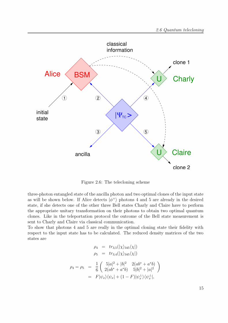
Figure 2.6: The telecloning scheme
three-photon entangled state of the ancilla photon and two optimal clones of the input stateas will be shown below. If Alice detects |φ+〉 photons 4 and 5 are already in the desiredstate, if she detects one of the other three Bell states Charly and Claire have to performthe appropriate unitary transformation on their photons to obtain two optimal quantumclones. Like in the teleportation protocol the outcome of the Bell state measurement issent to Charly and Claire via classical communication.To show that photons 4 and 5 are really in the optimal cloning state their fidelity withrespect to the input state has to be calculated. The reduced density matrices of the twostates are
ρ4 = tr3,5(|χ〉345〈χ|)ρ5 = tr3,4(|χ〉345〈χ|)
ρ4 = ρ5 =1
6
(5|a|2 + |b|2 2(ab∗ + a∗b)
2(ab∗ + a∗b) 5|b|2 + |a|2)
= F |ψx〉〈ψx|+ (1− F )|ψ⊥x 〉〈ψ⊥x |,
15
2 Theory
where F is the fidelity to the input state |ψx〉 given by
F = 〈ψx|ρ4,5|ψx〉
=(a∗ b∗
) 1
6
(5|a|2 + |b|2 2(ab∗ + a∗b)
2(ab∗ + a∗b) 5|b|2 + |a|2)(
ab
)
=5
6,
which is the maximum for a N = 1→M = 2 cloning process as shown in Eq. (2.1).
Entanglement structure during the telecloning process
Before the Bell state measurement the state is a direct product of the input state |ψx〉 andthe four-photon entangled telecloning state |ψTC〉. The telecloning state is a superpositionof a four-photon GHZ state and a product of two Bell states [8, 9]
|ψTC〉 =
√2
3|GHZ〉2345 +
√1
3|ψ+〉23|ψ+〉45
with the GHZ-term
|GHZ〉 =1√2
(|HHHH〉+ |V V V V 〉)
and the Bell state
|ψ+〉 =1√2
(|HV 〉+ |V H〉).
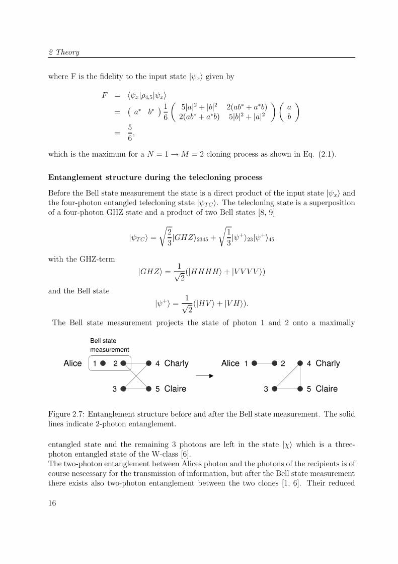
The Bell state measurement projects the state of photon 1 and 2 onto a maximally
Bell statemeasurement
4 Charly
5 Claire
2
3
1 Alice 2
3
1
5 Claire
4 CharlyAlice
Figure 2.7: Entanglement structure before and after the Bell state measurement. The solidlines indicate 2-photon entanglement.
entangled state and the remaining 3 photons are left in the state |χ〉 which is a three-photon entangled state of the W-class [6].The two-photon entanglement between Alices photon and the photons of the recipients is ofcourse nescessary for the transmission of information, but after the Bell state measurementthere exists also two-photon entanglement between the two clones [1, 6]. Their reduced
16

2.6 Quantum telecloning
two photon density matrix is
ρ45 = tr3(|χ〉345〈χ|) =2
3
|a|2 ab∗2
ab∗2
0a∗b2
14
14
ab∗2
a∗b2
14
14
ab∗2
0 a∗b2
a∗b2|b|2
. (2.2)
Because the telecloning process is universal it is sufficient to examine one input state, forexample |ψ〉x = |+〉. For a = b = 1√
2(2.2) becomes
ρ45 =2
3
12
14
14
014
14
14
14
14
14
14
14
0 14
14
12
. (2.3)
According to the Peres-Horodecki theorem [19, 20] the two-photon state is entangled if thepartial transpose of the states density matrix has at least one negative eigenvalue. Thepartial transpose of Eq. (2.3) is
ρT245 =
2
3
12
14
14
14
14
14
0 14
14
0 14
14
14
14
14
12
,
with the eigenvalues 14, 1
4, 1
4(2 −
√5) and 1
4(2 +
√5), where the third one is negative,
indicating two-photon entanglement between the two clones.
17

2 Theory
18
3 Implementation
In this chapter the building blocks for the realisation of the experiment are presented. Twobasic techniques of experimental quantum information are introduced, namely the use ofparametric down conversion as source of entangled photons in section 3.1, and interfero-metric Bell state analysis in section 3.2.The chapter starts with the description of the type-II spontaneous parametric down con-version process which was used for the generation of two- and four-photon entangled states[7, 9]. Two-photon states are obtained from first order emissions and were used to performquantum teleportation, while the four-photon states used for the implementation of quan-tum telecloning originate from second order emissions. In the latter case a postselection ofevents is necessary.Both teleportation and telecloning required the projetion of a weak coherent state and oneof the down conversion photons onto the Bell state basis. An interferometric method wasapplied with which two of the four Bell states can be identified [21]. The necessary overlapat a beam splitter was aligned by utilizing a two-photon interference effect, the so calledHong Ou Mandel dip [16]. The visibility of this dip provides a measure of quality for theBell state analysis. Furthermore the influence of beam splitter parameters, like transmis-sivity and reflectivity of different polarisations as well as phase shifts, on the Bell stateanalysis have been studied. For the case of phase shifts the possibilities of compensationare discussed.In section 3.3 it is explained how density matrices of photon states can be measured. Thistechnique was used for the analysis of the output states of the telecloning process.
3.1 Parametric down conversion
Type-II noncollinear phase matching in spontanous parametric down conversion (SPDC)allows the direct production of polarisation entangled photons out of a nonlinear crystal[7]. In the process of down conversion a pump photon decays into two daughter photons.Due to dispersion the momentum conservation can only be fulfilled in birefringent crystals,in our setup we used BBO (beta-barium borate). In type-II SPDC the pump beam hasordinary polarisation and the two emerging photons, called signal and idler photon, haveextraordinary and ordinary polarisation respectively. Due to the conservation of energy
3 Implementation
and momentum, i. e.
hωpump = hωsignal + hωidler
h~kpump = h~ksignal + h~kidler
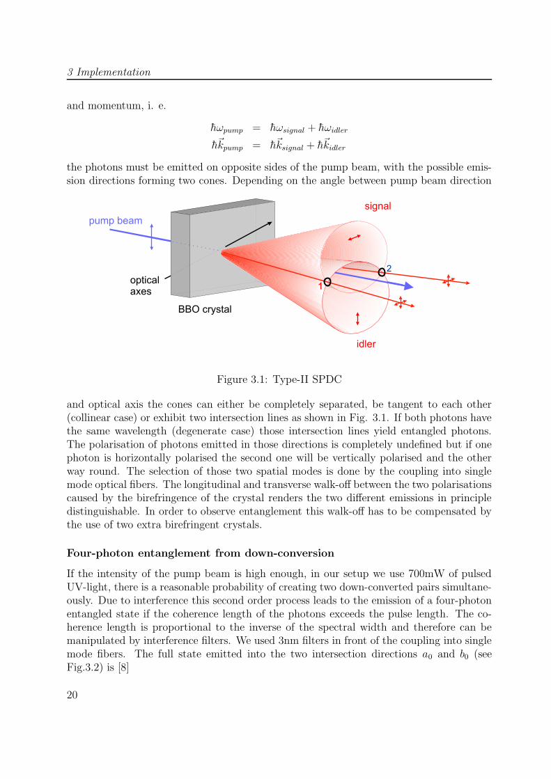
the photons must be emitted on opposite sides of the pump beam, with the possible emis-sion directions forming two cones. Depending on the angle between pump beam direction
Figure 3.1: Type-II SPDC
and optical axis the cones can either be completely separated, be tangent to each other(collinear case) or exhibit two intersection lines as shown in Fig. 3.1. If both photons havethe same wavelength (degenerate case) those intersection lines yield entangled photons.The polarisation of photons emitted in those directions is completely undefined but if onephoton is horizontally polarised the second one will be vertically polarised and the otherway round. The selection of those two spatial modes is done by the coupling into singlemode optical fibers. The longitudinal and transverse walk-off between the two polarisationscaused by the birefringence of the crystal renders the two different emissions in principledistinguishable. In order to observe entanglement this walk-off has to be compensated bythe use of two extra birefringent crystals.
Four-photon entanglement from down-conversion
If the intensity of the pump beam is high enough, in our setup we use 700mW of pulsedUV-light, there is a reasonable probability of creating two down-converted pairs simultane-ously. Due to interference this second order process leads to the emission of a four-photonentangled state if the coherence length of the photons exceeds the pulse length. The co-herence length is proportional to the inverse of the spectral width and therefore can bemanipulated by interference filters. We used 3nm filters in front of the coupling into singlemode fibers. The full state emitted into the two intersection directions a0 and b0 (seeFig.3.2) is [8]
20
3.1 Parametric down conversion
b0
a0
/2λ
BS
BS
PBS
PBS
PBS
PBS
BBO
multi coincidence counter
a
b
c
d
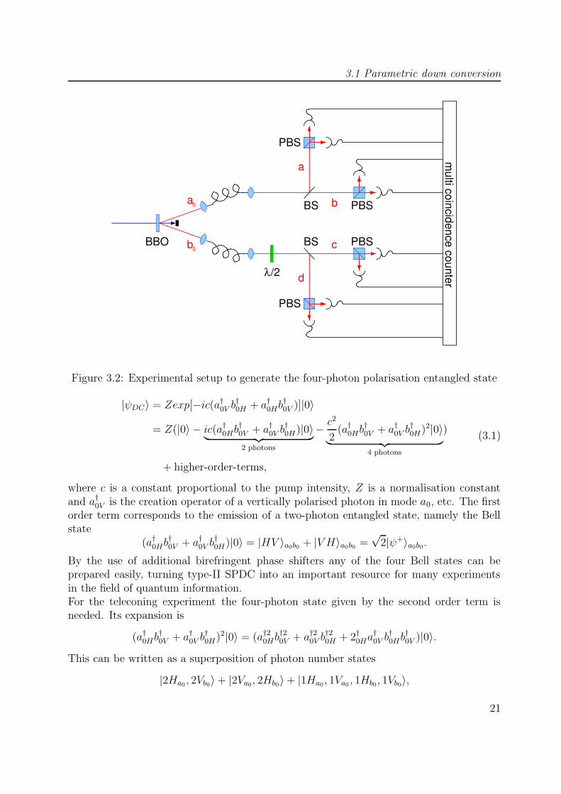
Figure 3.2: Experimental setup to generate the four-photon polarisation entangled state
|ψDC〉 = Zexp[−ic(a†0V b†0H + a†0Hb†0V )]|0〉
= Z(|0〉 − ic(a†0Hb†0V + a†0V b†0H)|0〉︸ ︷︷ ︸
2 photons
− c2
2(a†0Hb
†0V + a†0V b
†0H)2|0〉
︸ ︷︷ ︸4 photons
)
+ higher-order-terms,
(3.1)
where c is a constant proportional to the pump intensity, Z is a normalisation constantand a†0V is the creation operator of a vertically polarised photon in mode a0, etc. The firstorder term corresponds to the emission of a two-photon entangled state, namely the Bellstate
(a†0Hb†0V + a†0V b
†0H)|0〉 = |HV 〉a0b0 + |V H〉a0b0 =
√2|ψ+〉a0b0 .
By the use of additional birefringent phase shifters any of the four Bell states can beprepared easily, turning type-II SPDC into an important resource for many experimentsin the field of quantum information.For the teleconing experiment the four-photon state given by the second order term isneeded. Its expansion is
(a†0Hb†0V + a†0V b
†0H)2|0〉 = (a†20Hb
†20V + a†20V b
†20H + 2†0Ha
†0V b†0Hb
†0V )|0〉.
This can be written as a superposition of photon number states
|2Ha0 , 2Vb0〉+ |2Va0, 2Hb0〉+ |1Ha0 , 1Va0 , 1Hb0, 1Vb0〉,
21
3 Implementation
where for example 2Ha0 means two horizontally polarised photons in mode a0 (the dif-ferent representations of photon states are explained in the appendix). To separate thefour photons, the two output modes are split up at beam splitters and only those eventsare selected where one photon is detected in each output mode. The transformation ofsymmetric 50:50 beam splitter, which will be studied in detail in the next section, is givenby
a†0 →1√2
(b† + ia†) and b†0 →1√2
(c† + id†).
The selection of events leads to the following four photon state.
|ψ4〉abcd =1√3
[|HHV V 〉+ |V V HH〉
+1
2
(|HV V H〉+ |V HHV 〉
+ |HVHV 〉+ |V HVH〉)]abcd
To obtain the telecloning state the polarisation in one arm is rotated either by a half waveplate or by means of the polarisation controllers of the optical fiber.
|ψTC〉abcd =1√3
[|HHHH〉+ |V V V V 〉
+1
2
(|HVHV 〉+ |V HVH〉
+ |HV V H〉+ |V HHV 〉)]abcd
3.2 Bell state analysis
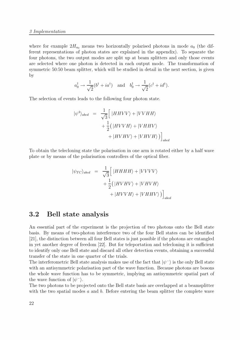
An essential part of the experiment is the projection of two photons onto the Bell statebasis. By means of two-photon interference two of the four Bell states can be identified[21], the distinction between all four Bell states is just possible if the photons are entangledin yet another degree of freedom [22]. But for teleportation and telecloning it is sufficientto identify only one Bell state and discard all other detection events, obtaining a successfultransfer of the state in one quarter of the trials.The interferometric Bell state analysis makes use of the fact that |ψ−〉 is the only Bell statewith an antisymmetric polarisation part of the wave function. Because photons are bosonsthe whole wave function has to be symmetric, implying an antisymmetric spatial part ofthe wave function of |ψ−〉.The two photons to be projected onto the Bell state basis are overlapped at a beamsplitterwith the two spatial modes a and b. Before entering the beam splitter the complete wave
22
3.2 Bell state analysis
a
b
functions of the four Bell states are:
|φ+〉 =1
2(|HH〉+ |V V 〉)(|ab〉+ |ba〉)
|φ−〉 =1
2(|HH〉 − |V V 〉)(|ab〉+ |ba〉)
|ψ+〉 =1
2(|HV 〉+ |V H〉)(|ab〉+ |ba〉)
|ψ−〉 =1
2(|HV 〉 − |V H〉)(|ab〉 − |ba〉).
The transformation matrix of a symmetric beam splitter with reflectivity r2 and transmis-sivity t2 in the {|a〉, |b〉} - basis is
B =
(t irir t
)
For a 50:50 splitting ratio with t = r = 1√2
the basis states transform like
|a〉 → 1√2
(|a〉+ i|b〉) and |b〉 → 1√2
(|b〉+ i|a〉)
Thus the transformations of the spatial parts of the wave functions are
1√2
(|ab〉+ |ba〉) → 1√2
(|aa〉+ |bb〉)1√2
(|ab〉 − |ba〉) → 1√2
(|ab〉 − |ba〉)
meaning that for |ψ−〉 both photons always leave the beam splitter in different outputmodes while for the other three Bell states both photons leave the beam splitter in thesame output mode, either both in mode a or both in mode b. Therefore the state |ψ−〉 canbe distinguished from the other Bell states. It is the only one that leads to coincidencesbetween two detectors in the output modes of the beamsplitter.
23

3 Implementation
We can further discriminate between the state |ψ+〉 and the states |φ±〉 by analysing thepolarisation of the photons in the output modes in the HV-basis. If the two photons arein the state |ψ+〉 they have different polarisation while in the other two cases they havethe same polarisation. The scheme is depicted in Fig. 3.3 where the blue lines mark
a
b
|Ψ +
|Ψ −>>
Figure 3.3: Bell state analyser for detecting the states |ψ−〉 and |ψ+〉
detection coincidences corresponding to the detection of |ψ−〉 and the red lines mark thosecorresponding to |ψ+〉.With setups similar to the one described here any two of the four Bell states can beidentified, for example if a PBS is used instead of a BS, it is possible to detect the states|φ+〉 and |φ−〉 [23].
3.2.1 Influences of beam splitter parameters on the Bell stateanalysis
In the preceding calculations an ideal beamsplitter with a 50:50 splitting ratio for all kindsof polarisations and without any effect on the polarisation has been assumed. But realbeamsplitters can have different splitting ratios, maybe even varying with different polari-sations or they can introduce phase shifts between two orthogonal polarisation components.In this section the effect of such divergences from the ideal beamsplitter transformation onthe Bell state analysis is investigated and it is shown how phase shifts can be compensated.How the beam splitter parameters have been determined is explained in the appendix.The most general transformation matrix of a beamsplitter in the {|Ha〉, |Hb〉, |V a〉, |V b〉}-basis, where for example |Ha〉 means horizontal polarisation in mode a, is given by
B =
tHaeiβHa rHbe
iαHb 0 0rHae
iαHa tHbeiβHb 0 0
0 0 tV aeiβV a rV be
iαV b
0 0 rV aeiαV a tV be
iβV b
, (3.2)
24
3.2 Bell state analysis
with the following conditions implied by the unitarity of B (the conservation of energy):
tHa = tHb≡ tH tV a = tV b ≡ tV (3.3)
rHa = rHb≡ rH rV a= rV b ≡ rV (3.4)
αHa − βHa = π + βHb − αHb (3.5)
αV a − βV a = π + βV b − αV b. (3.6)
Here t2Ha for example is the transmissivity for horizontal polarisation in mode a.Phase shifts occur if for a particular path the phase factor for H is different from the phasefactor for V, i. e.
αHa 6= αV a αHb 6= αV b
βHa 6= βV a βHb 6= βV b.
Such phase shifts cause all polarisation states other than |H〉 or |V 〉 to be rotated. Forexample if a photon in the state |+〉 enters the beamsplitter in arm a and is reflected inarm b the transformation is
|+〉 =1√2
(|H〉+ |V 〉) → 1√2eiαHa(|H〉+ ei(αV a−αHa)|V 〉),
which results in eliptical polarisation.
Special case: no phase shifts in the transmitted beams
The beamsplitters we used didn’t show any phase shifts in the transmitted beams, justas one would expect since they are made of non-birefringent material (BK7 glass with adielectric beam splitter coating). This means
βHa = βV a and βHb = βV b,
and Eqs. (3.5), (3.6) reduce to
αHa − αV a = −(αHb − αV b) ≡ ∆α. (3.7)
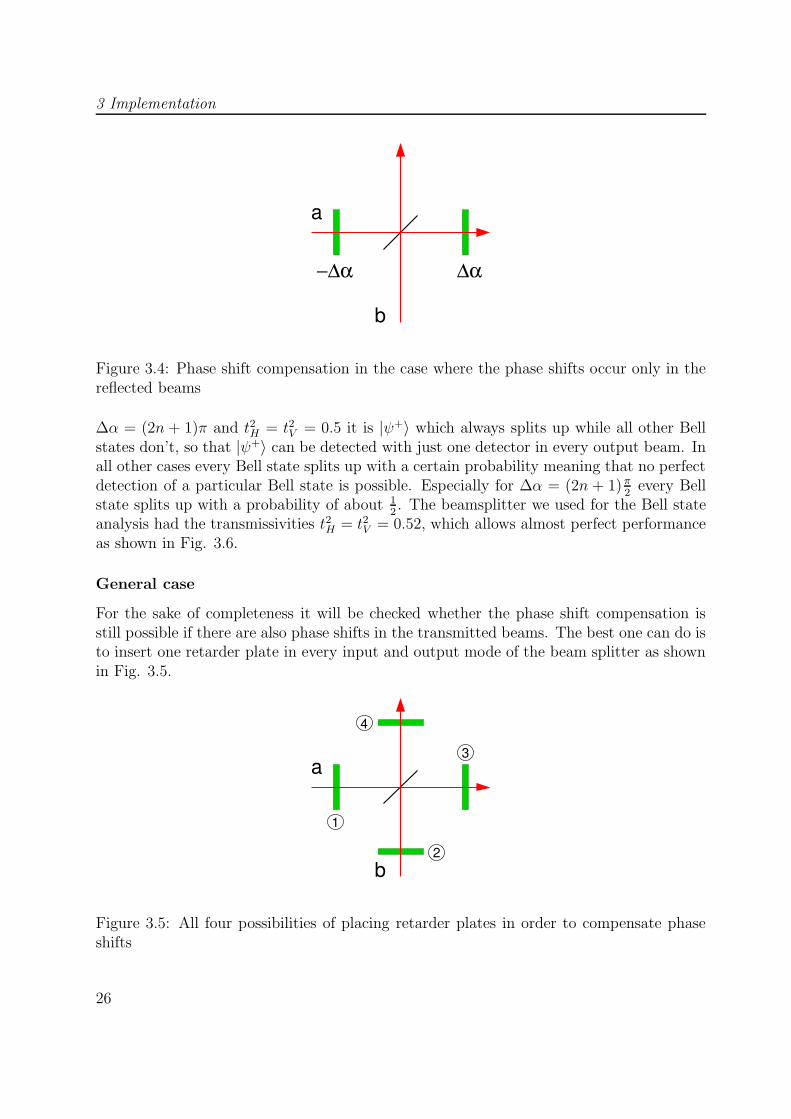
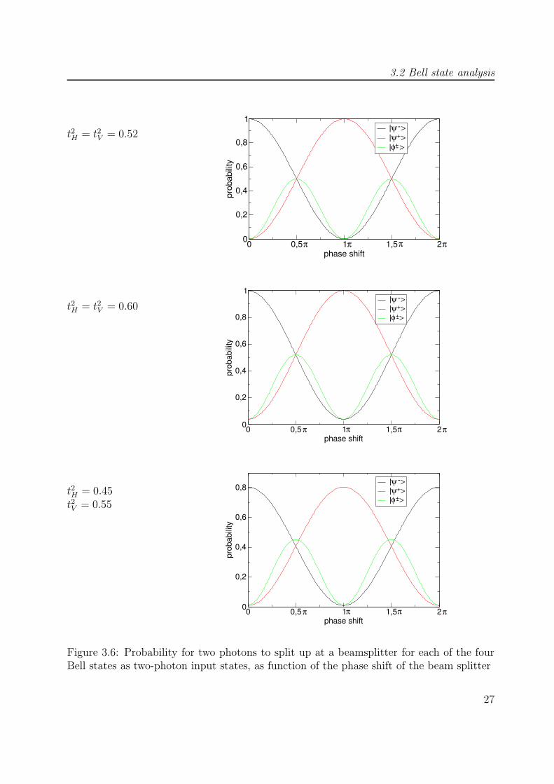
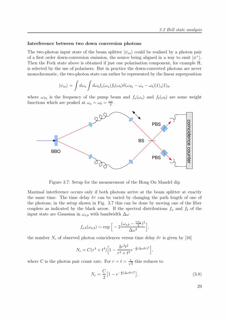
Thus the absolute values of the phase shifts in both reflected beams are the same and inthis case only two retarder plates are necessary for the compensation as shown in Fig. 3.4.The effect of such a phase shift on the Bell state analysis can be calculated by insertingthe conditions (3.3), (3.4) and (3.7) in the beamsplitter matrix (3.2) and applying thisbeamsplitter transformation on the Bell states. Then for every state the probability forthe two photons to split up at the beamsplitter can be calculated and plotted against thephase shift ∆α. In Figure 3.6 those probabilities are plotted against the phase shift ∆α for3 different values of the transmissivities t2H and t2V . The case where the state |ψ−〉 alwayssplits up and all other Bell states don’t, appears only if ∆α = 2nπ and t2H = t2V = 0.5. For
25
3 Implementation
a
b
−∆α ∆α
Figure 3.4: Phase shift compensation in the case where the phase shifts occur only in thereflected beams
∆α = (2n + 1)π and t2H = t2V = 0.5 it is |ψ+〉 which always splits up while all other Bellstates don’t, so that |ψ+〉 can be detected with just one detector in every output beam. Inall other cases every Bell state splits up with a certain probability meaning that no perfectdetection of a particular Bell state is possible. Especially for ∆α = (2n + 1) π
2every Bell
state splits up with a probability of about 12. The beamsplitter we used for the Bell state
analysis had the transmissivities t2H = t2V = 0.52, which allows almost perfect performanceas shown in Fig. 3.6.
General case
For the sake of completeness it will be checked whether the phase shift compensation isstill possible if there are also phase shifts in the transmitted beams. The best one can do isto insert one retarder plate in every input and output mode of the beam splitter as shownin Fig. 3.5.
a
b
3
4
2
1
Figure 3.5: All four possibilities of placing retarder plates in order to compensate phaseshifts
26
3.2 Bell state analysis
t2H = t2V = 0.52
0 0,5 1 1,5 2phase shift
0
0,2
0,4
0,6
0,8
1
prob
abili
ty
|ψ >|ψ >|φ >
+-
+-
π π π π
t2H = t2V = 0.60
0 0,5 1 1,5 2phase shift
0
0,2
0,4
0,6
0,8
1
prob
abili
ty
|ψ >|ψ >|φ >
+-
+-
π π π π
t2H = 0.45t2V = 0.55
0 0,5 1 1,5 2phase shift
0
0,2
0,4
0,6
0,8
prob
abili
ty
|ψ >|ψ >|φ >
+-
+-
π π π π
Figure 3.6: Probability for two photons to split up at a beamsplitter for each of the fourBell states as two-photon input states, as function of the phase shift of the beam splitter
27
3 Implementation
The complete transformation is then
B′ = C4C3BC2C1
with
C1/3 =
eiφ1/3 0 0 00 1 0 00 0 1 00 0 0 1
C2/4 =
1 0 0 00 eiφ2/4 0 00 0 1 00 0 0 1
,
resulting in
B′ =
tHei(βHa+φ1+φ3) rHe
i(αHb+φ2+φ3) 0 0rHe
i(αHa+φ1+φ4) tHei(βb+φ2+φ4) 0 0
0 0 tV eβV a rV e
iαV b
0 0 rV eiαV a tV e
iβV b
.
The phase shifts φ1, . . . φ4 of the retarder plates must be chosen in such a way that forevery path through the beamsplitter the phase factors for H and V are the same. Thisleads to the following conditions
φ1 = αV a − αHa − φ4
φ2 = βV b − βHb − φ4
φ3 = αHa − αV a + βV a − βHa + φ4
= −αHb + αV b − βV b + βHb + φ4,
which can always be fulfilled with just three plates since φ4 can be chosen arbitrarily andtherefore every possible phase shift of a beamsplitter can be compensated.
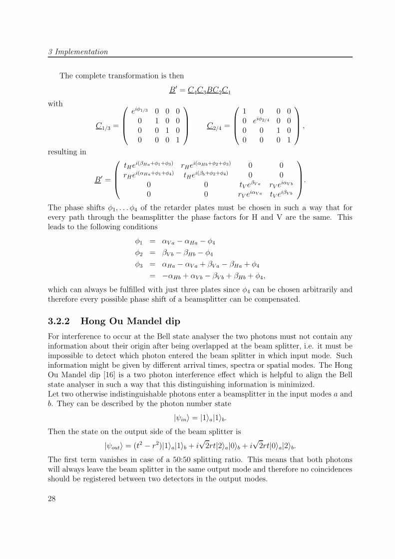
3.2.2 Hong Ou Mandel dip
For interference to occur at the Bell state analyser the two photons must not contain anyinformation about their origin after being overlapped at the beam splitter, i.e. it must beimpossible to detect which photon entered the beam splitter in which input mode. Suchinformation might be given by different arrival times, spectra or spatial modes. The HongOu Mandel dip [16] is a two photon interference effect which is helpful to align the Bellstate analyser in such a way that this distinguishing information is minimized.Let two otherwise indistinguishable photons enter a beamsplitter in the input modes a andb. They can be described by the photon number state
|ψin〉 = |1〉a|1〉b.Then the state on the output side of the beam splitter is
|ψout〉 = (t2 − r2)|1〉a|1〉b + i√
2rt|2〉a|0〉b + i√
2rt|0〉a|2〉b.The first term vanishes in case of a 50:50 splitting ratio. This means that both photonswill always leave the beam splitter in the same output mode and therefore no coincidencesshould be registered between two detectors in the output modes.
28
3.2 Bell state analysis
Interference between two down conversion photons
The two-photon input state of the beam splitter |ψin〉 could be realised by a photon pairof a first order down-conversion emission, the source being aligned in a way to emit |φ+〉.Then the Fock state above is obtained if just one polarisation component, for example H,is selected by the use of polarisers. But in practice the down-converted photons are nevermonochromatic, the two-photon state can rather be represented by the linear superposition
|ψin〉 =
∫dωa
∫dωbfa(ωa)fb(ωb)δ(ωP0 − ωa − ωb)|1〉a|1〉b,
where ωP0 is the frequency of the pump beam and fa(ωa) and fb(ωb) are some weightfunctions which are peaked at ωa = ωb = ωP
2.
PBS
PBS
BS
coincidence counter
BBO
Figure 3.7: Setup for the measurement of the Hong Ou Mandel dip
Maximal interference occurs only if both photons arrive at the beam splitter at exactlythe same time. The time delay δτ can be varied by changing the path length of one ofthe photons; in the setup shown in Fig. 3.7 this can be done by moving one of the fibercouplers as indicated by the black arrow. If the spectral distributions fa and fb of theinput state are Gaussian in ωa,b with bandwidth ∆ω
fa,b(ωa,b) ∼ exp[− 2
(ωa,b − ωP0
2)2
∆ω2
],
the number Nc of observed photon coincidences versus time delay δτ is given by [16]
Nc = C(r4 + t4)[1− 2r2t2
r4 + t4e−
18
(∆ωδτ)2],
where C is the photon pair count rate. For r = t = 1√2
this reduces to
Nc =C
2
[1− e− 1
8(∆ωδτ)2]
. (3.8)
29
3 Implementation
-1000 -750 -500 -250 0 250 500 750 1000delay/fs
0
0,1
0,2
0,3
0,4
0,5
0,6
coin
cide
nces
/C
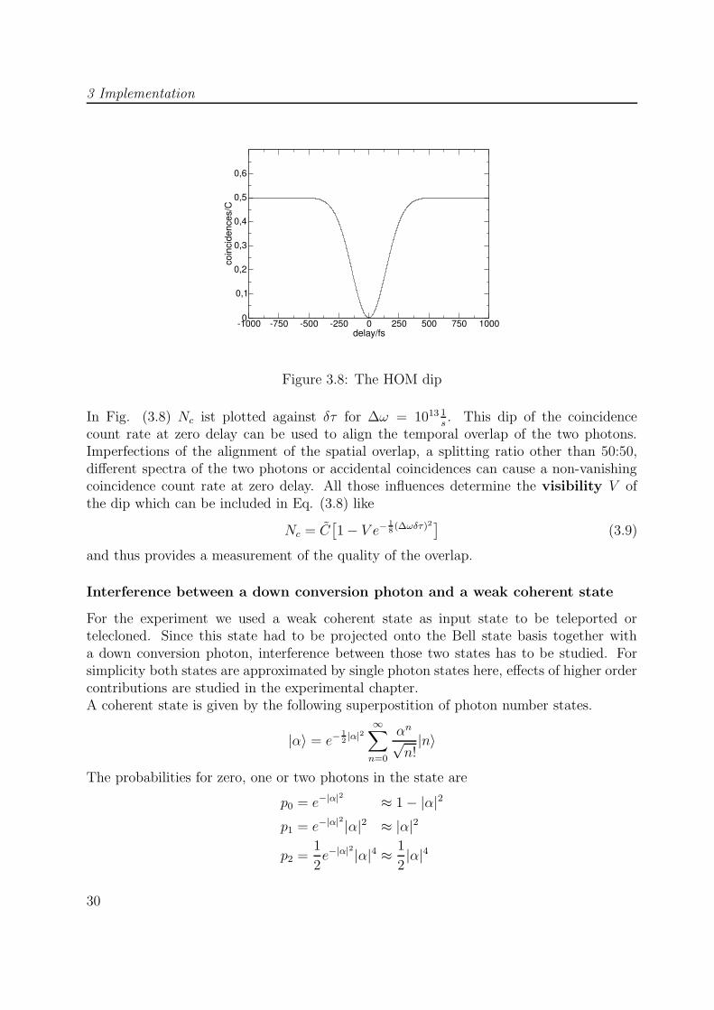
Figure 3.8: The HOM dip
In Fig. (3.8) Nc ist plotted against δτ for ∆ω = 1013 1s. This dip of the coincidence
count rate at zero delay can be used to align the temporal overlap of the two photons.Imperfections of the alignment of the spatial overlap, a splitting ratio other than 50:50,different spectra of the two photons or accidental coincidences can cause a non-vanishingcoincidence count rate at zero delay. All those influences determine the visibility V ofthe dip which can be included in Eq. (3.8) like
Nc = C[1− V e− 1
8(∆ωδτ)2]
(3.9)
and thus provides a measurement of the quality of the overlap.
Interference between a down conversion photon and a weak coherent state
For the experiment we used a weak coherent state as input state to be teleported ortelecloned. Since this state had to be projected onto the Bell state basis together witha down conversion photon, interference between those two states has to be studied. Forsimplicity both states are approximated by single photon states here, effects of higher ordercontributions are studied in the experimental chapter.A coherent state is given by the following superpostition of photon number states.
|α〉 = e−12|α|2
∞∑
n=0
αn√n!|n〉
The probabilities for zero, one or two photons in the state are
p0 = e−|α|2 ≈ 1− |α|2
p1 = e−|α|2|α|2 ≈ |α|2
p2 =1
2e−|α|
2|α|4 ≈ 1
2|α|4
30
3.2 Bell state analysis
PBS
PBS
BBOLBO
BSb
a
c
P
BS
PBS
LaserML
multi coincidence counter
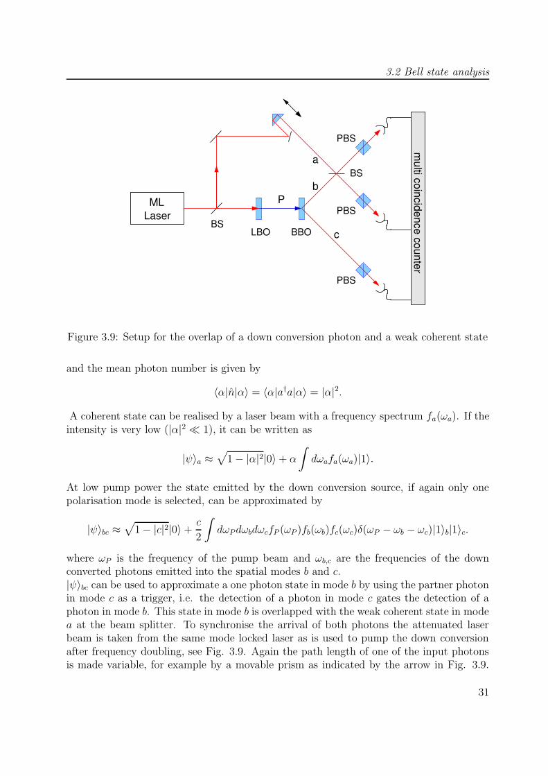
Figure 3.9: Setup for the overlap of a down conversion photon and a weak coherent state
and the mean photon number is given by
〈α|n|α〉 = 〈α|a†a|α〉 = |α|2.
A coherent state can be realised by a laser beam with a frequency spectrum fa(ωa). If theintensity is very low (|α|2 � 1), it can be written as
|ψ〉a ≈√
1− |α|2|0〉+ α
∫dωafa(ωa)|1〉.
At low pump power the state emitted by the down conversion source, if again only onepolarisation mode is selected, can be approximated by
|ψ〉bc ≈√
1− |c|2|0〉+c
2
∫dωPdωbdωcfP (ωP )fb(ωb)fc(ωc)δ(ωP − ωb − ωc)|1〉b|1〉c.
where ωP is the frequency of the pump beam and ωb,c are the frequencies of the downconverted photons emitted into the spatial modes b and c.|ψ〉bc can be used to approximate a one photon state in mode b by using the partner photonin mode c as a trigger, i.e. the detection of a photon in mode c gates the detection of aphoton in mode b. This state in mode b is overlapped with the weak coherent state in modea at the beam splitter. To synchronise the arrival of both photons the attenuated laserbeam is taken from the same mode locked laser as is used to pump the down conversionafter frequency doubling, see Fig. 3.9. Again the path length of one of the input photonsis made variable, for example by a movable prism as indicated by the arrow in Fig. 3.9.
31
3 Implementation
The frequency spectra of the different beams can be selected by interference filters. In thecase of Gaussian filter functions
fP (ωP ) ∼ exp[− 2
(ωP − ωP0)2
∆ω2P
]and fa,b(ω) ∼ exp
[− 2
(ω − ωP0
2)2
∆ω2
]
the coincidence count rate for two detectors in the output modes of the beam splitter asfunction of the time delay δτ is given by [17]
Nc = C[1− 2r2t2
r4 + t4V exp
[− (
δτ 2∆ω2
8(1 + ∆ω2
2∆ω2P
))]]
with V =
√1
1 + ∆ω2
2∆ω2P
, (3.10)
where r2 and t2 are the reflectivity and the transmissivity of the beam splitter. Comparedto the HOM dip of two down conversion photons (Eq. 3.2.2), the visibility of this dip isreduced by the factor V which is unity for ∆ω � ∆ωP and falls as ∆ω increases. For∆ω > ∆ωP it falls rapidly, corresponding to the fact that the photons are in principledistinguishable if the time uncertainty due to the spectral filtering (∼ ∆ω−1) is smallerthan the pulse duration (∼ ∆ω−1
P ). In this case also the width of the dip grows.
3.3 Measurement of density matrices
The state of a quantum system can be estimated on the basis of a sequence of measurementsdone on a large enough number of identically prepared copies of the quantum system [29].In the method of tomographic reconstruction the density matrix of the system is linearlyrelated to a set of measured quantities. Subsequent most likelihood estimation ensures themeasured density matrices to represent physical states. The procedure is presented for themeasurement of polarisation states of photons.
Single photon state tomography
The Pauli matrices form a basis of the two dimensional Hilbert space. Therefore anydensity matrix of a qubit, for example the polarisation state of a photon, can be writtenas a linear combination
ρ = a0σ0 + ~a~σ. (3.11)
The coefficients a0, . . . , a3 can be determined by four projection measurements given bythe four operators
µ0 = |H〉〈H| µ1 = |V 〉〈V |µ2 = |+〉〈+| µ3 = |R〉〈R|.
Note that this is just one example of infinitely many possible sets of operators.The expectation values for the number of detected photons are given by ni = Nitr(ρµi),where Ni is the number of photons which would be detected without polarisation analysis,
32
3.3 Measurement of density matrices
depending on the light intensity, detector efficiency and measurement time. Thus thecoefficients are obtained in the following way
a0 =1
2(〈H|ρ|H〉+ 〈V |ρ|V 〉) =
1
2
ax = 〈+|ρ|+〉 − a0 =n2
N2
− 1
2
ay = a0 − 〈R|ρ|R〉 =1
2− n3
N3
az = 〈H|ρ|H〉 − a0 =n0
N0+
1
2,
with the first equation including the normalisation property of density matrices, tr(ρ) = 1.For the examination of the copy states obtained in the teleportation and telecloning ex-periments, we were mainly interested in their fidelity with respect to the input state |ψin〉,which is given by
F = 〈ψin|ρcopy|ψin〉and can be obtained by a projection measurement corresponding to the operators
|ψin〉〈ψin| and |ψ⊥in〉〈ψ⊥in|.
Multiple photon state tomography
The method described above can be generalised for the measurement of density matricesof two or more photons. The state of an n-qubit system may be witten as
ρ =1
2n
3∑
i1,i2,...,in=0
ri1,i2,...,inσi1 ⊗ σi2 ⊗ · · · ⊗ σin
Analogous to the single photon case, the coefficients ri1,i2,...,in can be related to the outcomesof projection measurements represented by the 4n operators
µi1 ⊗ µi2 ⊗ · · · ⊗ µin with ik = 0, 1, 2, 3 and k = 1, 2, . . . n
A tomographically complete set of measurements for the case of a two-photon state andthe corresponding calculation of the entries of the density matrix can be found in [29].
Maximum likelihood estimation
The density matrices obtained by quantum state tomography are, by construction, nor-malised. But due to experimental noise they might fail to be Hermitian and positivesemidefinite, and therefore don’t correspond to a physical state. This problem can besolved by the application of the maximum likelihood estimation, in which the physicaldensity matrix being most likely to produce the experimental data is found by numerical
33
3 Implementation
optimisation.The idea is to define a matrix ρp as a function of 4n real parameters t1, . . . , t4n in such away, that it is always representing a physical density matrix of an n qubit system, and alikelihood function as the probability for ρp to produce the measured data set dependenton the parameters t1, . . . , t4n . The maximum of this function yields the optimal estimateof the measured density matrix. In [29] this function is calculated for the case of a twoqubit system.
34
4 Experiment
This chapter describes the experimental procedures and results. In Section 4.1 an overviewof the complete experimental setup is given, and some parts of it are studied in more detail.As described in section 3.1, the four-photon entangled state used for the implementationof quantum telecloning was obtained directly from parametric down conversion. A char-acterisation of the source, in form of a measurement of the countrate and the visibility ofthe correlations of the two- and four-photon states, is presented. It follows a descriptionof the preparation of the weak coherent state, which carried the polarisation state to betelecloned.The interference of the weak coherent state and one of the down conversion photons, whichwas necessary for the Bell state analysis, stongly depends on the spectra of the differentbeams and the pulse duration, as shown in section 3.2.2. Therefore the laser pulses werecharacterised by a measurement of their duration and spectrum, and the transmittance ofthe spectral filters has been checked. Finally it is descibed how the five-photon state wasanalysed.Section 4.2 deals with the stepwise alignment of the overlap of two beams at a beam splitterfor the Bell state analysis. We started with strong laser light, since it offered the possibilityof observing interference effects with a CCD camera or even with the naked eye. The tran-sition to quantum interference was done by measuring the Hong Ou Mandel dip betweentwo down conversion photons, since in this case it was much easier to find the temporaloverlap and the coincidence count rates were much higher as for the interference of a weakcoherent state and a down conversion photon, which followed in the last step.Finally the experimental results obtained for quantum teleportation and quantum tele-cloning are presented in sections 4.3 and 4.4. The measured fidelties of the output statesto the input states are shown, and for the telecloning also a measurement of the densitymatrices of the clones.
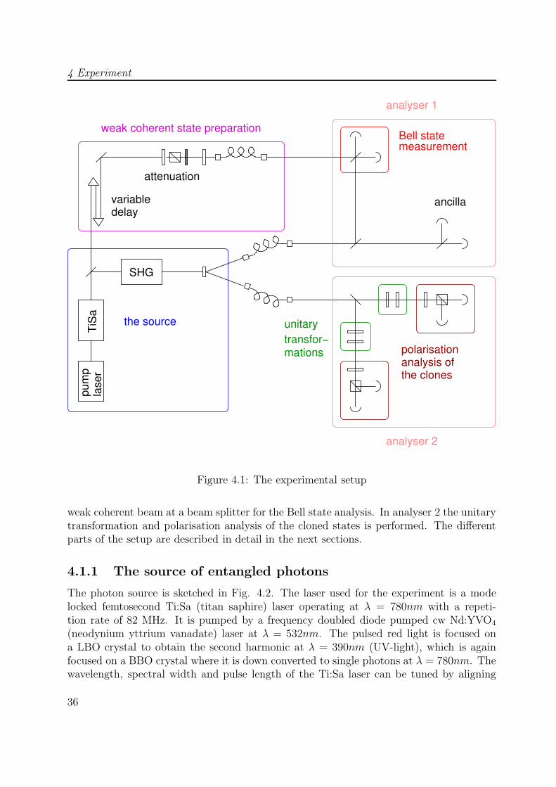
4.1 The setup
Fig. 4.1 shows the complete experimental setup. The same laser is used to pump thedown conversion source after frequency doubling and to provide the weak coherent beamafter strong attenuation. The two beams from down conversion are coupled into singlemode fibers and directed into two separate analysers, where they are split up at beamsplitters. In analyser 1 one of the output beams of the beam splitter is mixed with the
4 Experiment
TiS
ala
ser
pum
p
analysis ofpolarisation
the clones
transfor−mations
unitary
Bell statemeasurement
ancilladelayvariable
attenuation
weak coherent state preparation
SHG
the source
analyser 1
analyser 2
Figure 4.1: The experimental setup
weak coherent beam at a beam splitter for the Bell state analysis. In analyser 2 the unitarytransformation and polarisation analysis of the cloned states is performed. The differentparts of the setup are described in detail in the next sections.
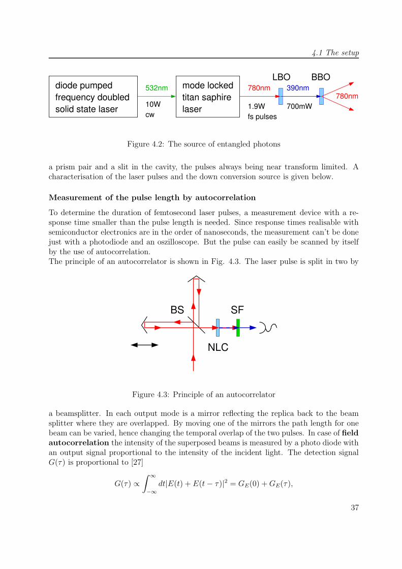
4.1.1 The source of entangled photons
The photon source is sketched in Fig. 4.2. The laser used for the experiment is a modelocked femtosecond Ti:Sa (titan saphire) laser operating at λ = 780nm with a repeti-tion rate of 82 MHz. It is pumped by a frequency doubled diode pumped cw Nd:YVO4
(neodynium yttrium vanadate) laser at λ = 532nm. The pulsed red light is focused ona LBO crystal to obtain the second harmonic at λ = 390nm (UV-light), which is againfocused on a BBO crystal where it is down converted to single photons at λ = 780nm. Thewavelength, spectral width and pulse length of the Ti:Sa laser can be tuned by aligning
36
4.1 The setup
mode lockedtitan saphirelaser
780nm
1.9Wfs pulses
700mW
LBO BBO
780nmfrequency doubleddiode pumped
solid state laser 10Wcw
532nm 390nm
Figure 4.2: The source of entangled photons
a prism pair and a slit in the cavity, the pulses always being near transform limited. Acharacterisation of the laser pulses and the down conversion source is given below.
Measurement of the pulse length by autocorrelation
To determine the duration of femtosecond laser pulses, a measurement device with a re-sponse time smaller than the pulse length is needed. Since response times realisable withsemiconductor electronics are in the order of nanoseconds, the measurement can’t be donejust with a photodiode and an oszilloscope. But the pulse can easily be scanned by itselfby the use of autocorrelation.The principle of an autocorrelator is shown in Fig. 4.3. The laser pulse is split in two by
BS
NLC
SF
Figure 4.3: Principle of an autocorrelator
a beamsplitter. In each output mode is a mirror reflecting the replica back to the beamsplitter where they are overlapped. By moving one of the mirrors the path length for onebeam can be varied, hence changing the temporal overlap of the two pulses. In case of fieldautocorrelation the intensity of the superposed beams is measured by a photo diode withan output signal proportional to the intensity of the incident light. The detection signalG(τ) is proportional to [27]
G(τ) ∝∫ ∞
−∞dt|E(t) + E(t− τ)|2 = GE(0) +GE(τ),
37
4 Experiment
where E(t) is the electric field strength of the pulse, τ is the time delay caused by the pathlength difference ∆l = cτ and
GE(τ) =
∫ ∞
−∞dt(E(t)E∗(t− τ) + E∗(t)E(t− τ)) =
1
π
∫ ∞
−∞dτ |E(ω)|2eiωτ
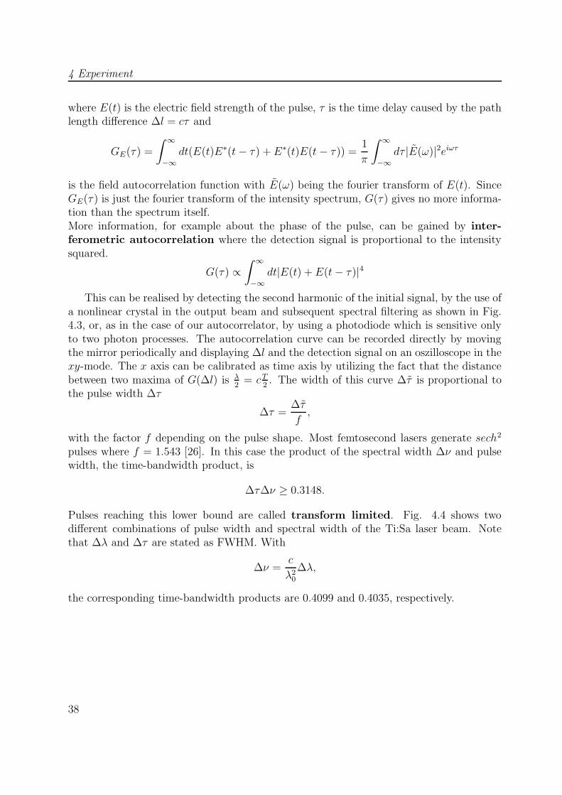
is the field autocorrelation function with E(ω) being the fourier transform of E(t). SinceGE(τ) is just the fourier transform of the intensity spectrum, G(τ) gives no more informa-tion than the spectrum itself.More information, for example about the phase of the pulse, can be gained by inter-ferometric autocorrelation where the detection signal is proportional to the intensitysquared.
G(τ) ∝∫ ∞
−∞dt|E(t) + E(t− τ)|4
This can be realised by detecting the second harmonic of the initial signal, by the use ofa nonlinear crystal in the output beam and subsequent spectral filtering as shown in Fig.4.3, or, as in the case of our autocorrelator, by using a photodiode which is sensitive onlyto two photon processes. The autocorrelation curve can be recorded directly by movingthe mirror periodically and displaying ∆l and the detection signal on an oszilloscope in thexy-mode. The x axis can be calibrated as time axis by utilizing the fact that the distancebetween two maxima of G(∆l) is λ
2= cT
2. The width of this curve ∆τ is proportional to
the pulse width ∆τ
∆τ =∆τ
f,
with the factor f depending on the pulse shape. Most femtosecond lasers generate sech2
pulses where f = 1.543 [26]. In this case the product of the spectral width ∆ν and pulsewidth, the time-bandwidth product, is
∆τ∆ν ≥ 0.3148.
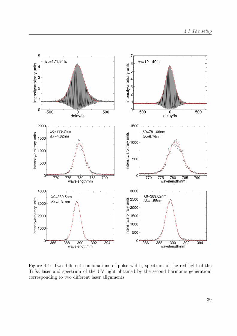
Pulses reaching this lower bound are called transform limited. Fig. 4.4 shows twodifferent combinations of pulse width and spectral width of the Ti:Sa laser beam. Notethat ∆λ and ∆τ are stated as FWHM. With
∆ν =c
λ20
∆λ,
the corresponding time-bandwidth products are 0.4099 and 0.4035, respectively.
38
4.1 The setup
-500 0 500delay/fs
0
1
2
3
4
5
inte
nsity
/arb
itrar
y un
its ∆τ=171,94fs
-500 0 500delay/fs
0
1
2
3
4
5
6
7
inte
nsity
/arb
itrar
y un
its
∆τ=121.40fs
770 775 780 785 790wavelength/nm
0
500
1000
1500
2000
inte
nsity
/arb
itrar
y un
its
λ0=779.7nm∆λ=4.82nm
770 775 780 785 790wavelength/nm
0
500
1000
1500in
tens
ity/a
rbitr
ary
units
λ∆λ
0=781.06nm=6.76nm
386 388 390 392 394wavelength/nm
0
1000
2000
3000
4000
inte
nsity
/arb
itrar
y un
its
0=389.5nm∆λ=1.31nmλ
386 388 390 392 394wavelength/nm
0
500
1000
1500
2000
2500
3000
inte
nsity
/arb
itrar
y un
its
λ0=389.62nm∆λ=1.55nm
Figure 4.4: Two different combinations of pulse width, spectrum of the red light of theTi:Sa laser and spectrum of the UV light obtained by the second harmonic generation,corresponding to two different laser alignments
39
4 Experiment
BBO
PBS
PBSBS
BSa
0
0
b
SFPBS
BS
SF
λ/2
λ/2
λ/2
PBS
λ/2
a
dc
multi coincidence counter
b
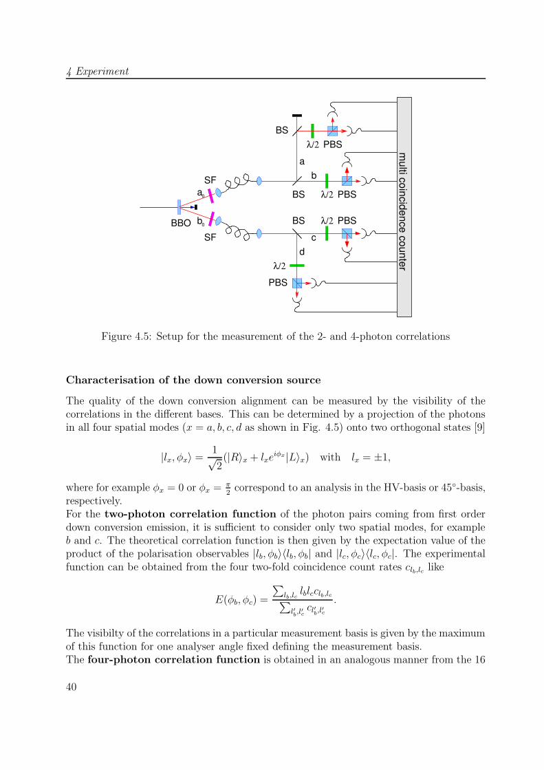
Figure 4.5: Setup for the measurement of the 2- and 4-photon correlations
Characterisation of the down conversion source
The quality of the down conversion alignment can be measured by the visibility of thecorrelations in the different bases. This can be determined by a projection of the photonsin all four spatial modes (x = a, b, c, d as shown in Fig. 4.5) onto two orthogonal states [9]
|lx, φx〉 =1√2
(|R〉x + lxeiφx|L〉x) with lx = ±1,
where for example φx = 0 or φx = π2
correspond to an analysis in the HV-basis or 45◦-basis,respectively.For the two-photon correlation function of the photon pairs coming from first orderdown conversion emission, it is sufficient to consider only two spatial modes, for exampleb and c. The theoretical correlation function is then given by the expectation value of theproduct of the polarisation observables |lb, φb〉〈lb, φb| and |lc, φc〉〈lc, φc|. The experimentalfunction can be obtained from the four two-fold coincidence count rates clb,lc like
E(φb, φc) =
∑lb,lc
lblcclb,lc∑l′b,l′ccl′b,l′c
.
The visibilty of the correlations in a particular measurement basis is given by the maximumof this function for one analyser angle fixed defining the measurement basis.The four-photon correlation function is obtained in an analogous manner from the 16
40
4.1 The setup
four-fold coincidences cla,lb,lc,ld
E(φa, φb, φc, φd) =
∑la,lb,lc,ld
lalblcldcla,lb,lc,ld∑l′a,l′b,l
′cl′dcl′a,l′b,l′c,l′d
.
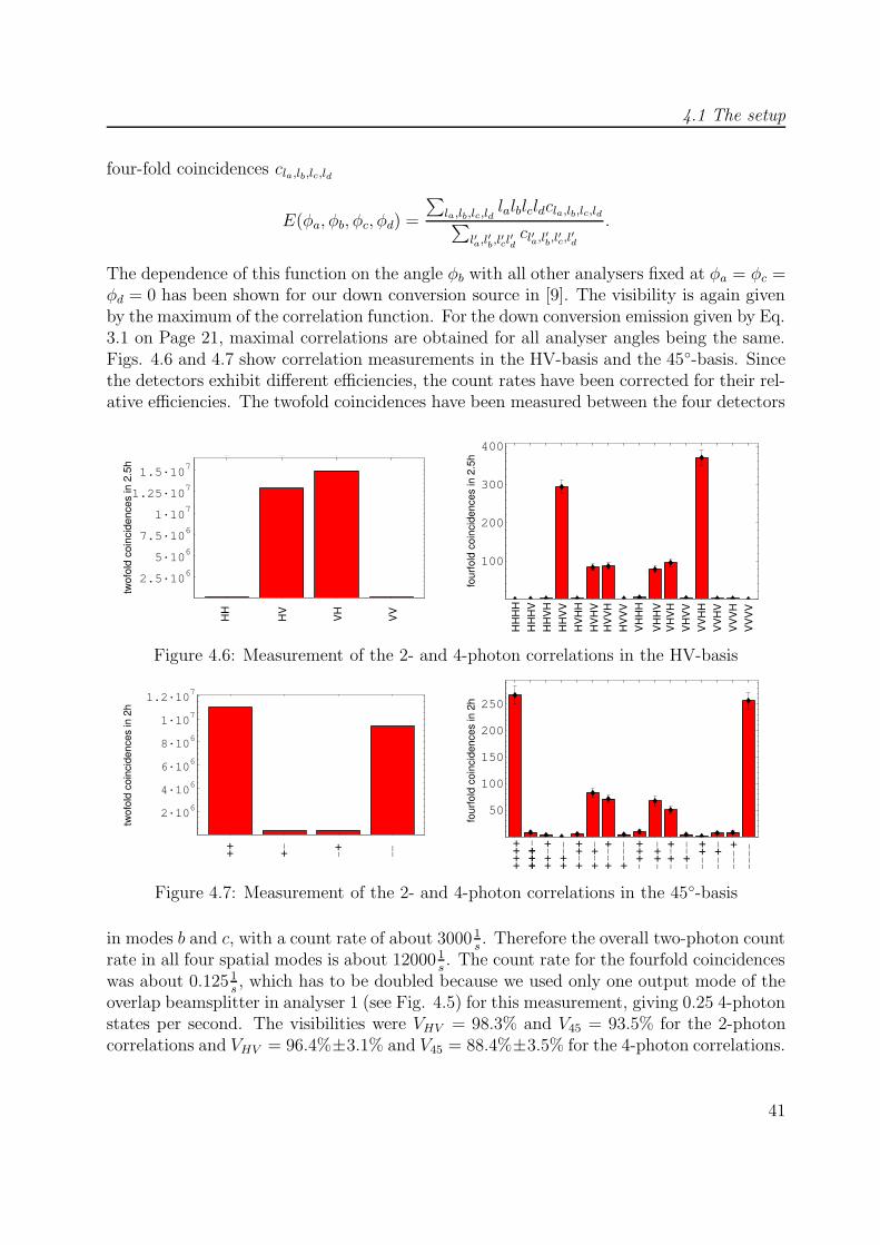
The dependence of this function on the angle φb with all other analysers fixed at φa = φc =φd = 0 has been shown for our down conversion source in [9]. The visibility is again givenby the maximum of the correlation function. For the down conversion emission given by Eq.3.1 on Page 21, maximal correlations are obtained for all analyser angles being the same.Figs. 4.6 and 4.7 show correlation measurements in the HV-basis and the 45◦-basis. Sincethe detectors exhibit different efficiencies, the count rates have been corrected for their rel-ative efficiencies. The twofold coincidences have been measured between the four detectors
1 2 3 4
2.5·106
5·106
7.5·106
1·107
1.25·107
1.5·107
1 2 3 4
HH
HV
VH
VV
twof
old
coin
cide
nces
in 2
.5h
1 2 3 4 5 6 7 8 9 10111213141516
100
200
300
4001 2 3 4 5 6 7 8 9 10111213141516
HH
HH
HH
VH
HH
VV
HV
HH
HV
HV
HV
VH
HV
VV
VH
HH
VH
HV
VH
VH
VH
VV
VV
HH
VV
HV
VV
VH
VV
VV
HH
HV
four
fold
coi
ncid
ence
s in
2.5
h
Figure 4.6: Measurement of the 2- and 4-photon correlations in the HV-basis
1 2 3 4
2·106
4·106
6·106
8·106
1·107
1.2·107 1 2 3 4
+ +_
_++ __
twof
old
coin
cide
nces
in 2
h
1 2 3 4 5 6 7 8 9 10111213141516
50
100
150
200
250
1 2 3 4 5 6 7 8 9 10111213141516
four
fold
coi
ncid
ence
s in
2h
++++
++ +
++ + +
++
++
+
+ +++
++
+ +
+ +
+
+
+++
+++
_
_ __
_
__
__
__
_
_
__ _
_
__
_
__
__
_
__
_
+
__
__
Figure 4.7: Measurement of the 2- and 4-photon correlations in the 45◦-basis
in modes b and c, with a count rate of about 3000 1s. Therefore the overall two-photon count
rate in all four spatial modes is about 12000 1s. The count rate for the fourfold coincidences
was about 0.125 1s, which has to be doubled because we used only one output mode of the
overlap beamsplitter in analyser 1 (see Fig. 4.5) for this measurement, giving 0.25 4-photonstates per second. The visibilities were VHV = 98.3% and V45 = 93.5% for the 2-photoncorrelations and VHV = 96.4%±3.1% and V45 = 88.4%±3.5% for the 4-photon correlations.
41
4 Experiment
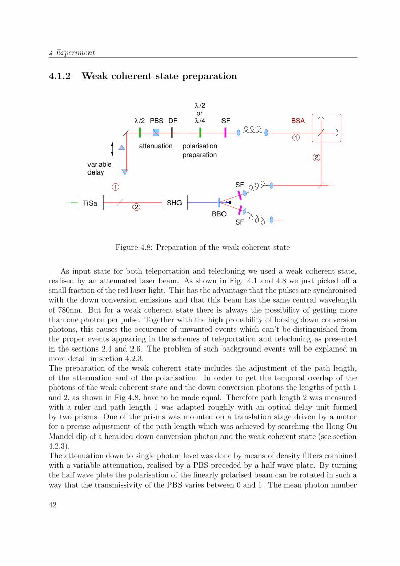
4.1.2 Weak coherent state preparation
variabledelay
λ /2
polarisationpreparation
λ /4
SHG
λ /2
TiSa
1
2
1
2
DFPBSor
BSA
attenuation
SF
SF
SFBBO
Figure 4.8: Preparation of the weak coherent state
As input state for both teleportation and telecloning we used a weak coherent state,realised by an attenuated laser beam. As shown in Fig. 4.1 and 4.8 we just picked off asmall fraction of the red laser light. This has the advantage that the pulses are synchronisedwith the down conversion emissions and that this beam has the same central wavelengthof 780nm. But for a weak coherent state there is always the possibility of getting morethan one photon per pulse. Together with the high probability of loosing down conversionphotons, this causes the occurence of unwanted events which can’t be distinguished fromthe proper events appearing in the schemes of teleportation and telecloning as presentedin the sections 2.4 and 2.6. The problem of such background events will be explained inmore detail in section 4.2.3.The preparation of the weak coherent state includes the adjustment of the path length,of the attenuation and of the polarisation. In order to get the temporal overlap of thephotons of the weak coherent state and the down conversion photons the lengths of path 1and 2, as shown in Fig 4.8, have to be made equal. Therefore path length 2 was measuredwith a ruler and path length 1 was adapted roughly with an optical delay unit formedby two prisms. One of the prisms was mounted on a translation stage driven by a motorfor a precise adjustment of the path length which was achieved by searching the Hong OuMandel dip of a heralded down conversion photon and the weak coherent state (see section4.2.3).The attenuation down to single photon level was done by means of density filters combinedwith a variable attenuation, realised by a PBS preceded by a half wave plate. By turningthe half wave plate the polarisation of the linearly polarised beam can be rotated in such away that the transmissivity of the PBS varies between 0 and 1. The mean photon number
42
4.1 The setup
per pulse |α|2 can be measured with the relation
|α|2 =1
R(S1
η1+S2
η2)
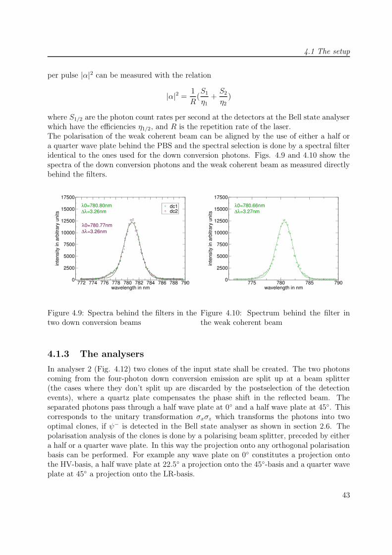
where S1/2 are the photon count rates per second at the detectors at the Bell state analyserwhich have the efficiencies η1/2, and R is the repetition rate of the laser.The polarisation of the weak coherent beam can be aligned by the use of either a half ora quarter wave plate behind the PBS and the spectral selection is done by a spectral filteridentical to the ones used for the down conversion photons. Figs. 4.9 and 4.10 show thespectra of the down conversion photons and the weak coherent beam as measured directlybehind the filters.
772 774 776 778 780 782 784 786 788 790wavelength in nm
0
2500
5000
7500
10000
12500
15000
17500
inte
nsity
in a
rbitr
ary
units
dc1dc2
0=780.80nm=3.26nm
λ∆λ
λ0=780.77nm∆λ=3.26nm
Figure 4.9: Spectra behind the filters in thetwo down conversion beams
775 780 785 790wavelength in nm
0
2500
5000
7500
10000
12500
15000
17500
inte
nsity
in a
rbitr
ary
units
0=780.66nm=3.27nm
λ∆λ
Figure 4.10: Spectrum behind the filter inthe weak coherent beam
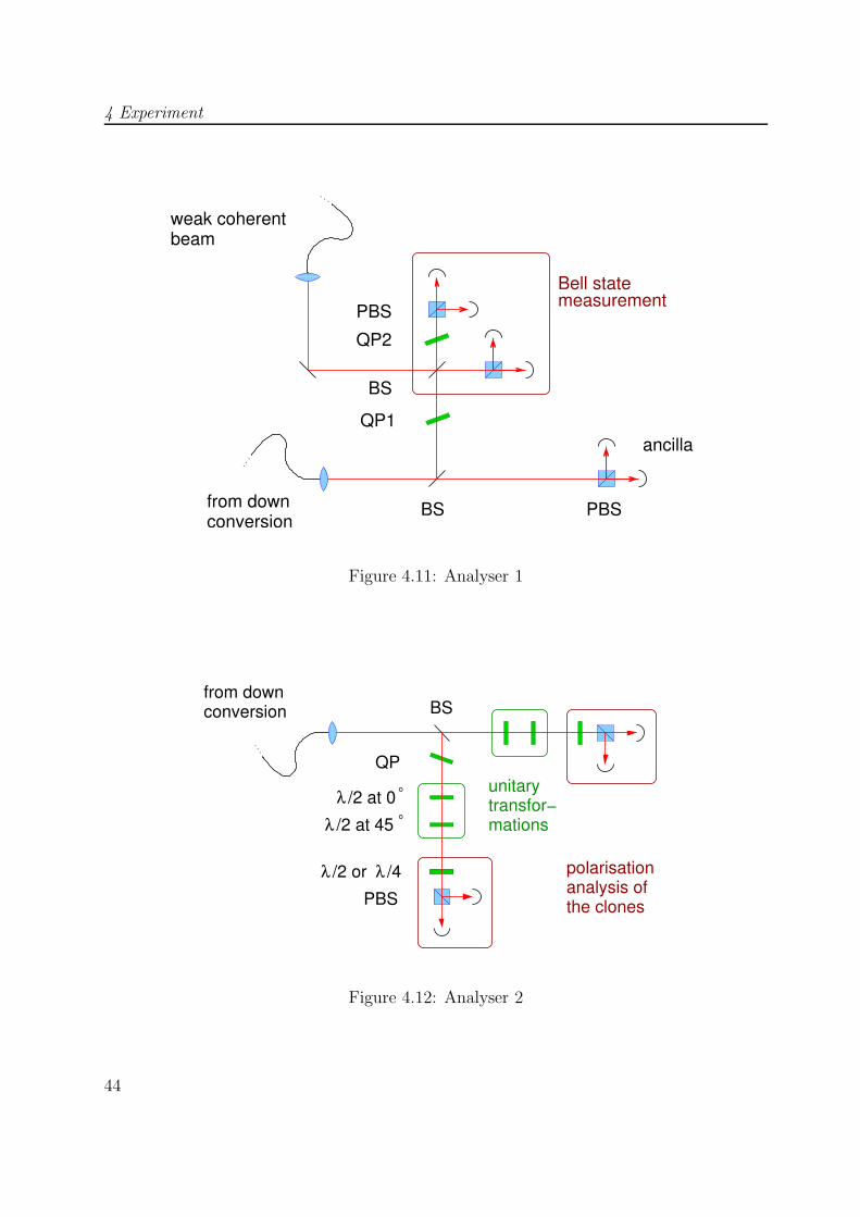
4.1.3 The analysers
In analyser 2 (Fig. 4.12) two clones of the input state shall be created. The two photonscoming from the four-photon down conversion emission are split up at a beam splitter(the cases where they don’t split up are discarded by the postselection of the detectionevents), where a quartz plate compensates the phase shift in the reflected beam. Theseparated photons pass through a half wave plate at 0◦ and a half wave plate at 45◦. Thiscorresponds to the unitary transformation σxσz which transforms the photons into twooptimal clones, if ψ− is detected in the Bell state analyser as shown in section 2.6. Thepolarisation analysis of the clones is done by a polarising beam splitter, preceded by eithera half or a quarter wave plate. In this way the projection onto any orthogonal polarisationbasis can be performed. For example any wave plate on 0◦ constitutes a projection ontothe HV-basis, a half wave plate at 22.5◦ a projection onto the 45◦-basis and a quarter waveplate at 45◦ a projection onto the LR-basis.
43
4 Experiment
Bell statemeasurement
from downconversion
weak coherentbeam
PBS
BS
PBS
ancilla
BS
QP2
QP1
Figure 4.11: Analyser 1
λ /2 at 45o
λ /2 at 0o
λ /2 or /4λ polarisation
the clonesanalysis of
unitarytransfor−mations
from downconversion
PBS
QP
BS
Figure 4.12: Analyser 2
44
4.2 The overlap
In analyser 1 (Fig. 4.11) three photons are detected, two photons from down conversionand one photon derived from the weak coherent beam representing the input state. Thedown conversion photons are again split up at a beam splitter. One of them is just detectedas ancilla photon, which is necessary for the postselection of events. Without detectingit, one would not know whether the photons really split up at the beam splitter. Thesecond photon is overlapped with the input state at the Bell state analyser. The alignmentof this overlap will be described in section 4.2. The phase shift compensation could beimplemented with two quartz plates as described in section 3.2.1. In this case the quartzplate QP1 compensates the joint phase shift of both beam splitters.Due to the low losses of the optical components used in the setup and to the variablefocussing provided by a movable lens used for the outcoupling of the fibers, an overallcoupling efficiency from single mode fiber to the multimode fiber of the detectors of about95% could be achieved in both analysers. The detection was done with passive quenchedfiber pigtailed Si-avalanche photo diodes (APDs) connected to a multi coincidence unitallowing the registration of all 28 = 256 possible coincidences between 8 detectors at once.This unit was specially designed for the detection of four or five photon states [24]. Sinceit was not possible to process the signals of more than 8 detectors, two of the ten detectorsshown in Fig. 4.12 and 4.11 had to be discarded. The identification of |ψ−〉 can bedone with just two detectors in the Bell state analyser, therefore the other two detectorsand the polarising beam splitters were removed for the telecloning experiment. For theteleportation which was done with the two-photon states from first order down conversion,the two detectors in the ancilla arm were of no use and could be removed. In this case theBell state analysis was done with all four detectors.
4.2 The overlap
A crucial part of the experiment was the alignment of the overlap between one photonof the 4-photon entangled state emitted by the down-conversion source and the weakcoherent state at a beam splitter, in order to perform the Bell state analysis. This hasbeen accomplished in a stepwise process, starting with the interference of visible cw laserlight to find the spatial overlap, then switching to pulsed laser light for the temporaloverlap. The next step was the transition to quantum interference by aligning the HongOu Mandel dip (see section 3.2.2) between two down conversion photons. Finally the weakcoherent state was overlapped with a photon from first order down conversion.
4.2.1 Classical interference
As first step the spatial overlap was aligned with the light of a laser diode at λ = 785nm.The light was coupled into a single mode fiber beam splitter whose output modes werecrossed at the beam splitter as shown in Fig. 4.13. One of the fiber outcouplers wasmounted on two translation stages to have the possibilty of varying its position in bothdirections orthogonal to the output beam. Additionally the position of the outcoupling
45

4 Experiment
PIN diode
CCD camera
from laser
Figure 4.13: Setup for the alignment of the overlap
lense could be changed so that the output angle as well as the focussing could be optimised.The quality of the alignment was checked with a CCD camera in one of the ouput modes.The goal was to achieve the same position and shape for both beams at two camerapositions separated by approximately 2m. A successful alignment results in a blinkingimage of the beam cross section, since fluctuations in the phase shifts of the two beamscause alternating constructive and destructive interference, whereas a bad alignment givesrise to interference fringes. Fig. 4.14 shows an example of such an image taken with theCCD camera. With the spatial modes being well aligned the temporal overlap could besearched, i.e. the path lengths for both beams in the analyser were made equal. Thereforethe pulsed light of the titan saphire laser was coupled into the fiber beam splitter. Thesecond output coupler was mounted on a translation stage with which the position inbeam direction and thus the path length could be varied. This stage had a motor drivenby a computer program which simultaneously registered the voltage at a PIN diode in theoutput beam of the beam splitter. The plot of this voltage against the motor positionexhibits interference fringes with a gaussian envelope, which are maximal for zero delay ofthe two pulses. Such a measurement is shown in Fig. 4.15. The fit gives a maximal voltageof 7.526V and a minimal voltage of 0.186V , resulting in a visibilty of V=95.2%.
4.2.2 Interference between two down conversion photons
The next step for the alignment of the overlap was the change to single photon level,i.e. the Hong Ou Mandel dip between two down conversion photons was measured. Themeasurement was carried out exactly as decribed in section 3.2.2 on page 28 with the setupshown in Fig. 3.7. The detection was now done with two APDs in the output modes of thebeam splitter and the coincidences between them were detected with the multi coincidenceunit and recorded as function of the path length difference.
46

4.2 The overlap
Figure 4.14: Cross section of the overlapping beams, recorded with a CCD camera inthe output mode of the beam splitter. In this example the horizontal overlap is not wellaligned.
-0,08 -0,06 -0,04 -0,02 0 0,02 0,04 0,06 0,08delay/microns
0
1
2
3
4
5
6
7
8
U/V
Umax =7.526V
Umin =0.186V
V=95.2%
Figure 4.15: Intensity of the overlapping beams against the path length difference (pulsedlaser as light cource), measured by the voltage of a PIN diode in the output of the beamsplitter.
47
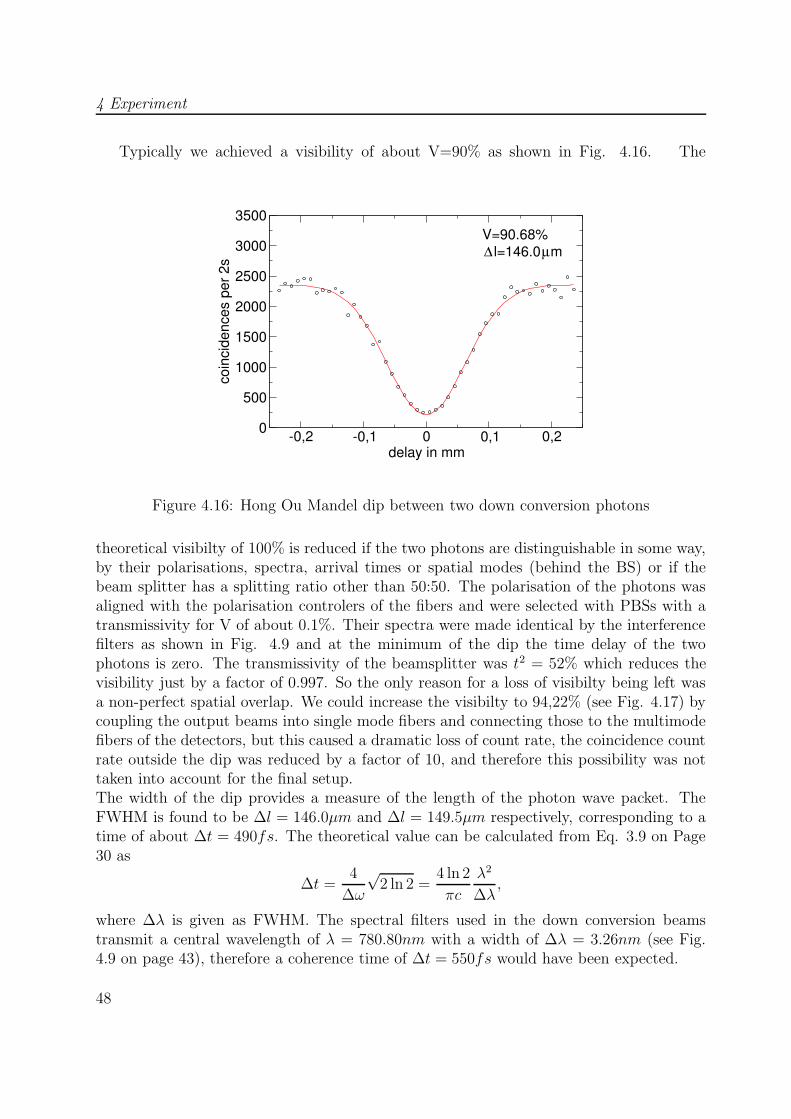
4 Experiment
Typically we achieved a visibility of about V=90% as shown in Fig. 4.16. The
-0,2 -0,1 0 0,1 0,2delay in mm
0
500
1000
1500
2000
2500
3000
3500co
inci
denc
es p
er 2
sV=90.68%
l=146.0µm∆
Figure 4.16: Hong Ou Mandel dip between two down conversion photons
theoretical visibilty of 100% is reduced if the two photons are distinguishable in some way,by their polarisations, spectra, arrival times or spatial modes (behind the BS) or if thebeam splitter has a splitting ratio other than 50:50. The polarisation of the photons wasaligned with the polarisation controlers of the fibers and were selected with PBSs with atransmissivity for V of about 0.1%. Their spectra were made identical by the interferencefilters as shown in Fig. 4.9 and at the minimum of the dip the time delay of the twophotons is zero. The transmissivity of the beamsplitter was t2 = 52% which reduces thevisibility just by a factor of 0.997. So the only reason for a loss of visibilty being left wasa non-perfect spatial overlap. We could increase the visibilty to 94,22% (see Fig. 4.17) bycoupling the output beams into single mode fibers and connecting those to the multimodefibers of the detectors, but this caused a dramatic loss of count rate, the coincidence countrate outside the dip was reduced by a factor of 10, and therefore this possibility was nottaken into account for the final setup.The width of the dip provides a measure of the length of the photon wave packet. TheFWHM is found to be ∆l = 146.0µm and ∆l = 149.5µm respectively, corresponding to atime of about ∆t = 490fs. The theoretical value can be calculated from Eq. 3.9 on Page30 as
∆t =4
∆ω
√2 ln 2 =
4 ln 2
πc
λ2
∆λ,
where ∆λ is given as FWHM. The spectral filters used in the down conversion beamstransmit a central wavelength of λ = 780.80nm with a width of ∆λ = 3.26nm (see Fig.4.9 on page 43), therefore a coherence time of ∆t = 550fs would have been expected.
48
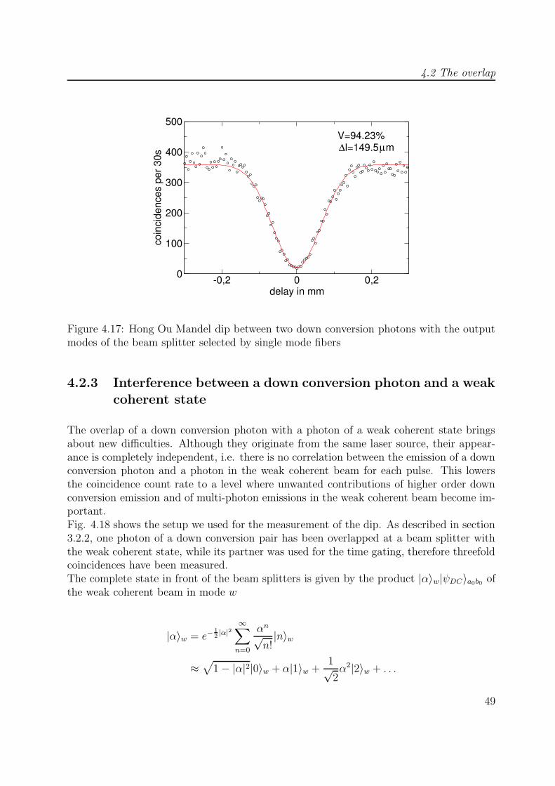
4.2 The overlap
-0,2 0 0,2delay in mm
0
100
200
300
400
500
coin
cide
nces
per
30s
V=94.23%l=149.5µm∆
Figure 4.17: Hong Ou Mandel dip between two down conversion photons with the outputmodes of the beam splitter selected by single mode fibers
4.2.3 Interference between a down conversion photon and a weakcoherent state
The overlap of a down conversion photon with a photon of a weak coherent state bringsabout new difficulties. Although they originate from the same laser source, their appear-ance is completely independent, i.e. there is no correlation between the emission of a downconversion photon and a photon in the weak coherent beam for each pulse. This lowersthe coincidence count rate to a level where unwanted contributions of higher order downconversion emission and of multi-photon emissions in the weak coherent beam become im-portant.Fig. 4.18 shows the setup we used for the measurement of the dip. As described in section3.2.2, one photon of a down conversion pair has been overlapped at a beam splitter withthe weak coherent state, while its partner was used for the time gating, therefore threefoldcoincidences have been measured.The complete state in front of the beam splitters is given by the product |α〉w|ψDC〉a0b0 ofthe weak coherent beam in mode w
|α〉w = e−12|α|2
∞∑
n=0
αn√n!|n〉w
≈√
1− |α|2|0〉w + α|1〉w +1√2α2|2〉w + . . .
49
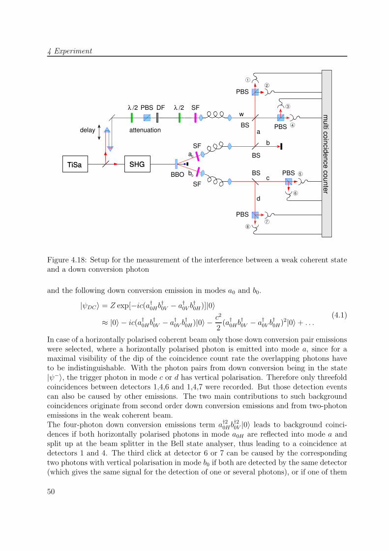
4 Experiment
TiSa
1
3
2
4
/2λ/2λ
SHGSHGTiSaBBO
PBS
PBS
PBS
PBSBS
BS
BSa
b
c
d
a
0
0
w
87
6
5b
SF
SF
SF
delay
PBS
attenuation
multi coincidence counter
DF
Figure 4.18: Setup for the measurement of the interference between a weak coherent stateand a down conversion photon
and the following down conversion emission in modes a0 and b0.
|ψDC〉 = Z exp[−ic(a†0Hb†0V − a†0V b†0H)]|0〉
≈ |0〉 − ic(a†0Hb†0V − a†0V b†0H)|0〉 − c2
2(a†0Hb
†0V − a†0V b†0H)2|0〉+ . . .
(4.1)
In case of a horizontally polarised coherent beam only those down conversion pair emissionswere selected, where a horizontally polarised photon is emitted into mode a, since for amaximal visibility of the dip of the coincidence count rate the overlapping photons haveto be indistinguishable. With the photon pairs from down conversion being in the state|ψ−〉, the trigger photon in mode c or d has vertical polarisation. Therefore only threefoldcoincidences between detectors 1,4,6 and 1,4,7 were recorded. But those detection eventscan also be caused by other emissions. The two main contributions to such backgroundcoincidences originate from second order down conversion emissions and from two-photonemissions in the weak coherent beam.The four-photon down conversion emissions term a†20Hb
†20V |0〉 leads to background coinci-
dences if both horizontally polarised photons in mode a0H are reflected into mode a andsplit up at the beam splitter in the Bell state analyser, thus leading to a coincidence atdetectors 1 and 4. The third click at detector 6 or 7 can be caused by the correspondingtwo photons with vertical polarisation in mode b0 if both are detected by the same detector(which gives the same signal for the detection of one or several photons), or if one of them
50
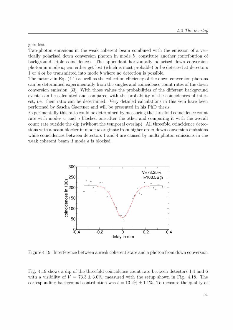
4.2 The overlap
gets lost.Two-photon emissions in the weak coherent beam combined with the emission of a ver-tically polarised down conversion photon in mode b0 constitute another contribution ofbackground triple coincidences. The appendant horizontally polarised down conversionphoton in mode a0 can either get lost (which is most probable) or be detected at detectors1 or 4 or be transmitted into mode b where no detection is possible.The factor c in Eq. (4.1) as well as the collection efficiency of the down conversion photonscan be determined experimentally from the singles and coincidence count rates of the downconversion emission [33]. With those values the probabilities of the different backgroundevents can be calculated and compared with the probability of the coincidences of inter-est, i.e. their ratio can be determined. Very detailed calculations in this vein have beenperformed by Sascha Gaertner and will be presented in his PhD thesis.Experimentally this ratio could be determined by measuring the threefold coincidence countrate with modes w and a blocked one after the other and comparing it with the overallcount rate outside the dip (without the temporal overlap). All threefold coincidence detec-tions with a beam blocker in mode w originate from higher order down conversion emissionswhile coincidences between detectors 1 and 4 are caused by multi-photon emissions in theweak coherent beam if mode a is blocked.
-0,4 -0,2 0 0,2 0,4delay in mm
0
50
100
150
200
250
300
coin
cide
nces
in 1
00s
V=73.25%l=163.5µm
Figure 4.19: Interference between a weak coherent state and a photon from down conversion
Fig. 4.19 shows a dip of the threefold coincidence count rate between detectors 1,4 and 6with a visibility of V = 73.3 ± 3.0%, measured with the setup shown in Fig. 4.18. Thecorresponding background contribution was b = 13.2%± 1.1%. To measure the quality of
51
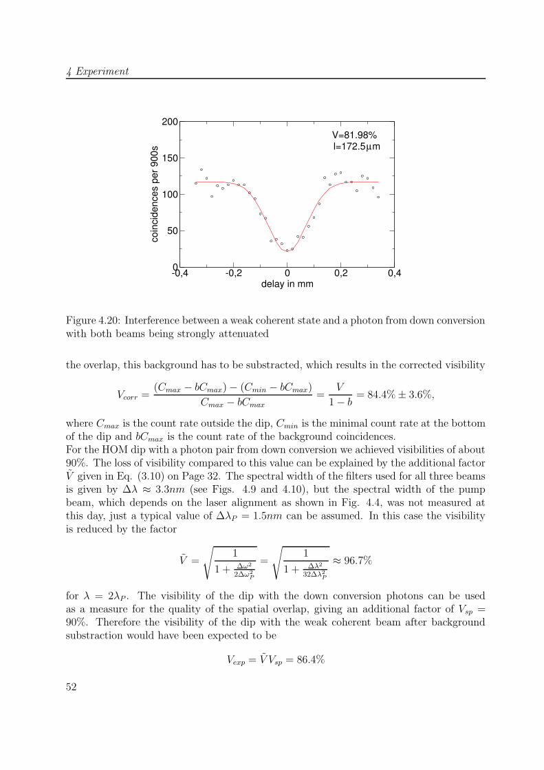
4 Experiment
-0,4 -0,2 0 0,2 0,4delay in mm
0
50
100
150
200
coin
cide
nces
per
900
s
V=81.98%l=172.5µm
Figure 4.20: Interference between a weak coherent state and a photon from down conversionwith both beams being strongly attenuated
the overlap, this background has to be substracted, which results in the corrected visibility
Vcorr =(Cmax − bCmax)− (Cmin − bCmax)
Cmax − bCmax=
V
1− b = 84.4%± 3.6%,
where Cmax is the count rate outside the dip, Cmin is the minimal count rate at the bottomof the dip and bCmax is the count rate of the background coincidences.For the HOM dip with a photon pair from down conversion we achieved visibilities of about90%. The loss of visibility compared to this value can be explained by the additional factorV given in Eq. (3.10) on Page 32. The spectral width of the filters used for all three beamsis given by ∆λ ≈ 3.3nm (see Figs. 4.9 and 4.10), but the spectral width of the pumpbeam, which depends on the laser alignment as shown in Fig. 4.4, was not measured atthis day, just a typical value of ∆λP = 1.5nm can be assumed. In this case the visibilityis reduced by the factor
V =
√1
1 + ∆ω2
2∆ω2P
=
√1
1 + ∆λ2
32∆λ2P
≈ 96.7%
for λ = 2λP . The visibility of the dip with the down conversion photons can be usedas a measure for the quality of the spatial overlap, giving an additional factor of Vsp =90%. Therefore the visibility of the dip with the weak coherent beam after backgroundsubstraction would have been expected to be
Vexp = V Vsp = 86.4%
52

4.3 Quantum teleportation
which lies within the error range of the measured value. By lowering the power of the pumpbeam of the down conversion source by means of an iris to about 100mW and attenuatingthe coherent beam even stronger, the background contribution could be reduced to 5.4%±1.6%. At the same time the overall count rate of threefold coincidences outside the dipwas reduced from 2.1 1
s(see Fig. 4.19) to 0.13 1
s. In this way the visibility of the dip could
be increased to V = 82.0% ± 3.2% (see Fig. 4.20). Background substraction leads to thecorrected value Vcorr = 86.7%±3.7%, which is even closer to the expected value calculatedabove.
4.3 Quantum teleportation
Quantum teleportation was performed with the setup shown in Fig. 4.18. The input statewas realised by approximating the ideal of a single photon with a specific polarisation statewith the component |1〉 of the polarised weak coherent state in mode w. The Bell state|ψ−〉 was provided by the first order down conversion emission into modes a0 and b0. Ifthe photon in mode a0 was reflected into mode a, it was projected onto the Bell state basistogether with the photon of the weak coherent beam. The Bell state analyser consisted ofa beam splitter and two polarising beam splitters in its output modes, allowing the identi-fication of |ψ+〉 and |ψ−〉. Since we had no possibility to change the unitary transformationof the third photon depending on the outcome of the Bell state measurement, we confinedourselfes to the detection of |ψ−〉. In this case no unitary transformation is necessary, andtherefore the third photon in mode c or d just had to be analysed, i.e. projected ontosome polarisation basis by the use of a half or quarter wave plate and a polarising beamsplitter. We always chose the eigenbase of the input state for the analysis of the copy stateto obtain its fidelity to the input state, as shown in section 3.3.Figs. 4.21, 4.22, 4.23 and 4.24 show the teleportation of four different input states.Each plot shows threefold coincidences corresponding to the detection of |ψ−〉aw|ψin〉c and|ψ−〉aw|ψ⊥in〉c versus the path length difference cδτ implied by the movement of the prismin the coherent beam. Since the detectors exhibit different detection efficiencies, the mea-sured count rates have been corrected for their relative efficiencies.In case of the input state |H〉 for example we used the polarising beam splitters in modes cand d without waveplates for the projection of the copy state onto the HV-basis. Threefoldcoincidences between detectors 1,3,5 and 2,4,5 both represent detections of |ψ−〉aw|H〉c andhave been summed up, as well as threefold coincidences between detectors 1,3,6 and 2,4,6which correspond to the detection of |ψ−〉aw|V 〉c. In this case the fidelity of the copy stateto the input state equals the probabilty of the detection of H in mode c which is given by
FH =CH
CH + CVat cδτ = 0,
where CH/V is the threefold coincidence countrates with a horizontally/vertically polarisedphoton in mode c. The same can be done for the copies reflected into mode d. The resulting
53
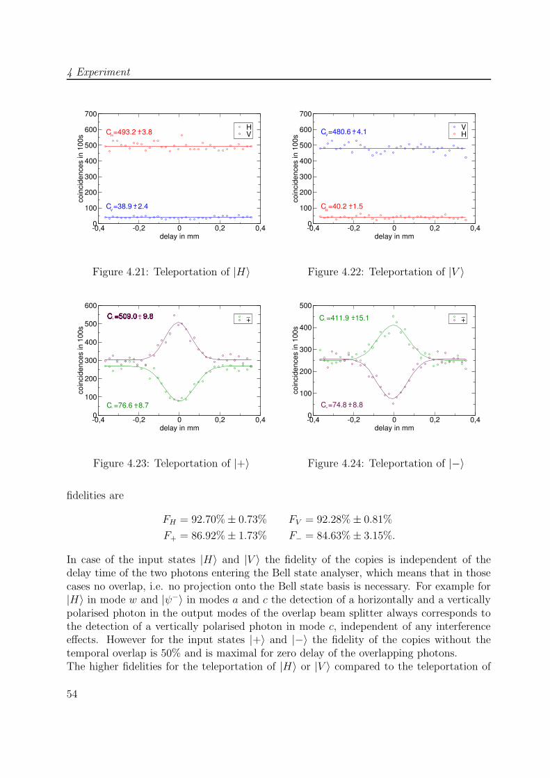
4 Experiment
-0,4 -0,2 0 0,2 0,4delay in mm
0
100
200
300
400
500
600
700
coin
cide
nces
in 1
00s
HVC =493.2 3.8
C =38.9 2.4+-
-+H
V
V
Figure 4.21: Teleportation of |H〉
-0,4 -0,2 0 0,2 0,4delay in mm
0
100
200
300
400
500
600
700
coin
cide
nces
in 1
00s
VHC =480.6 4.1
C =40.2 1.5+-
-+V
H
Figure 4.22: Teleportation of |V 〉
-0,4 -0,2 0 0,2 0,4delay in mm
0
100
200
300
400
500
600
coin
cide
nces
in 1
00s
++C =509.0 9.8-
C =76.6 8.7
_
-
C =509.0 9.8C =509.0 9.8C =509.0 9.8C =509.0 9.8C =509.0 9.8
+
+
-
Figure 4.23: Teleportation of |+〉
-0,4 -0,2 0 0,2 0,4delay in mm
0
100
200
300
400
500co
inci
denc
es in
100
s
+C =411.9 15.1
C =74.8 8.8
_+-
+
-
+-
Figure 4.24: Teleportation of |−〉
fidelities are
FH = 92.70%± 0.73% FV = 92.28%± 0.81%
F+ = 86.92%± 1.73% F− = 84.63%± 3.15%.
In case of the input states |H〉 and |V 〉 the fidelity of the copies is independent of thedelay time of the two photons entering the Bell state analyser, which means that in thosecases no overlap, i.e. no projection onto the Bell state basis is necessary. For example for|H〉 in mode w and |ψ−〉 in modes a and c the detection of a horizontally and a verticallypolarised photon in the output modes of the overlap beam splitter always corresponds tothe detection of a vertically polarised photon in mode c, independent of any interferenceeffects. However for the input states |+〉 and |−〉 the fidelity of the copies without thetemporal overlap is 50% and is maximal for zero delay of the overlapping photons.The higher fidelities for the teleportation of |H〉 or |V 〉 compared to the teleportation of
54
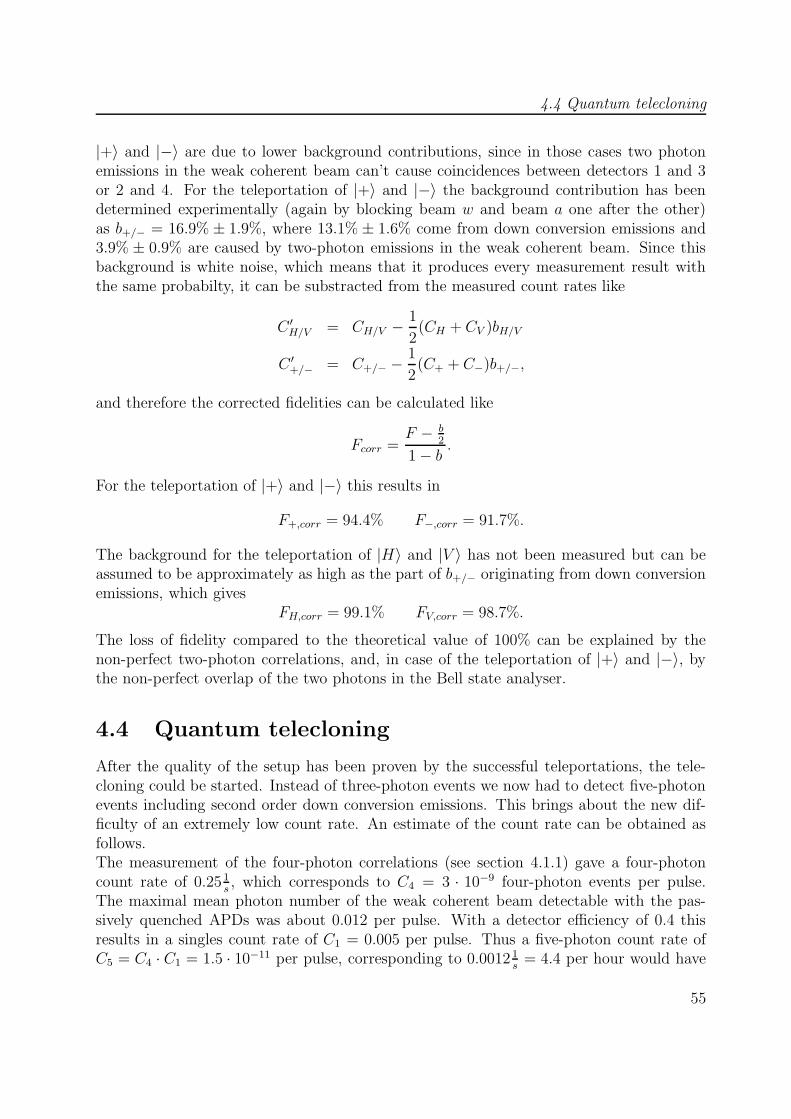
4.4 Quantum telecloning
|+〉 and |−〉 are due to lower background contributions, since in those cases two photonemissions in the weak coherent beam can’t cause coincidences between detectors 1 and 3or 2 and 4. For the teleportation of |+〉 and |−〉 the background contribution has beendetermined experimentally (again by blocking beam w and beam a one after the other)as b+/− = 16.9% ± 1.9%, where 13.1% ± 1.6% come from down conversion emissions and3.9% ± 0.9% are caused by two-photon emissions in the weak coherent beam. Since thisbackground is white noise, which means that it produces every measurement result withthe same probabilty, it can be substracted from the measured count rates like
C ′H/V = CH/V −1
2(CH + CV )bH/V
C ′+/− = C+/− −1
2(C+ + C−)b+/−,
and therefore the corrected fidelities can be calculated like
Fcorr =F − b
2
1− b .
For the teleportation of |+〉 and |−〉 this results in
F+,corr = 94.4% F−,corr = 91.7%.
The background for the teleportation of |H〉 and |V 〉 has not been measured but can beassumed to be approximately as high as the part of b+/− originating from down conversionemissions, which gives
FH,corr = 99.1% FV,corr = 98.7%.
The loss of fidelity compared to the theoretical value of 100% can be explained by thenon-perfect two-photon correlations, and, in case of the teleportation of |+〉 and |−〉, bythe non-perfect overlap of the two photons in the Bell state analyser.
4.4 Quantum telecloning
After the quality of the setup has been proven by the successful teleportations, the tele-cloning could be started. Instead of three-photon events we now had to detect five-photonevents including second order down conversion emissions. This brings about the new dif-ficulty of an extremely low count rate. An estimate of the count rate can be obtained asfollows.The measurement of the four-photon correlations (see section 4.1.1) gave a four-photoncount rate of 0.25 1
s, which corresponds to C4 = 3 · 10−9 four-photon events per pulse.
The maximal mean photon number of the weak coherent beam detectable with the pas-sively quenched APDs was about 0.012 per pulse. With a detector efficiency of 0.4 thisresults in a singles count rate of C1 = 0.005 per pulse. Thus a five-photon count rate ofC5 = C4 · C1 = 1.5 · 10−11 per pulse, corresponding to 0.0012 1
s= 4.4 per hour would have
55
4 Experiment
been expected. Since we detected just one of the four Bell states and discarded all otherdetection events, this has to be divided by 4, which results in a count rate of 1.2 eventsper hour.During the first measurements we really obtained 1 to 1.5 events per hour. To get theerror on the fidelity of the clones below 5%, at least 100 detection events were needed,which requires a measurement time of the order of three days. Since it was very hardwork to keep the whole system stable for such a long time, we decided to exchange thetwo passively quenched APDs in the Bell state analyser by two actively quenched APDs.The dead time of those diodes is reduced by fast electronics accomplishing the quenchingand recharging after an avalanche breakdown [34], which leads to a higher efficiency andto possible count rates of up to 107 counts per second. Because the multi coincidence unitcan process a maximal number of 8 · 105 detection events per second [24] and because allfivefold coincidences of interest included a coincidence between the two detectors in theBell state analyser (if |ψ−〉 is detected), we used an additional two channel coincidenceunit to transform coincidences between those detectors into single signals to be sent to theeight channel unit. The new setup is shown in Fig. 4.25.
TiSa
/2λ/2λ1
2
3
4
/2λ
/2λ
SHGSHGTiSaBBO
PBS
PBSBS
BSa
0
0
87
6
5b
SF
SF
delay
PBS
BS
wSFDFPBS
attenuation
twofoldcoincidence
counter
multi coincidence counterd
c
ba
Figure 4.25: Telecloning setup
4.4.1 Telecloning of three different input states
For the telecloning experiment we measured fivefold coincidences between the two detectorsin the Bell state analyser (corresponding to the detection of |ψ−〉), one detector in mode
56
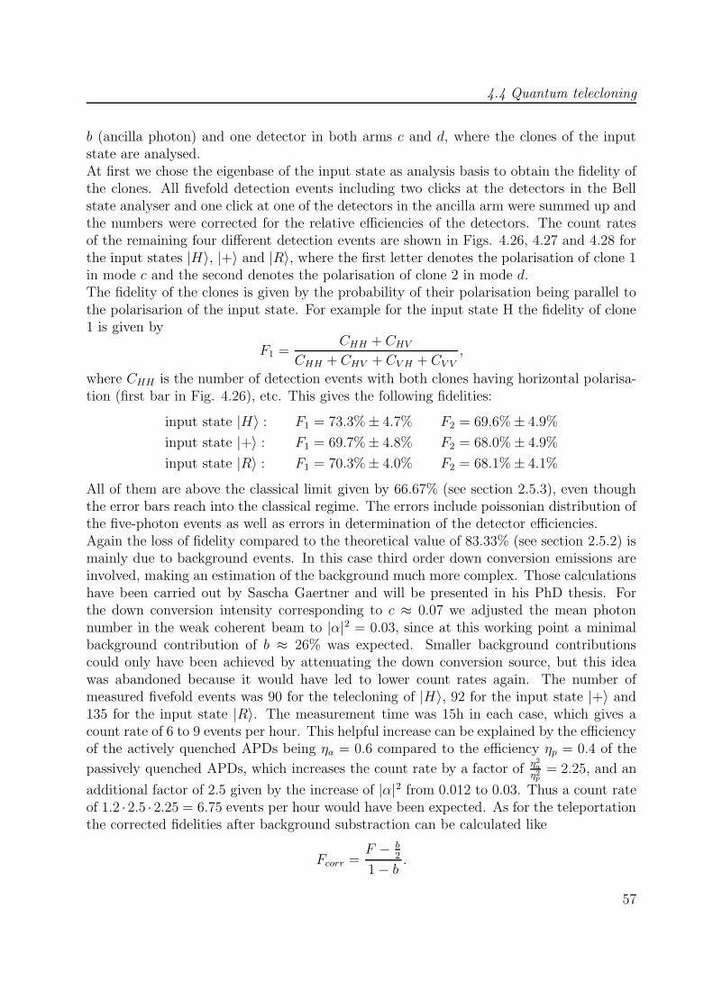
4.4 Quantum telecloning
b (ancilla photon) and one detector in both arms c and d, where the clones of the inputstate are analysed.At first we chose the eigenbase of the input state as analysis basis to obtain the fidelity ofthe clones. All fivefold detection events including two clicks at the detectors in the Bellstate analyser and one click at one of the detectors in the ancilla arm were summed up andthe numbers were corrected for the relative efficiencies of the detectors. The count ratesof the remaining four different detection events are shown in Figs. 4.26, 4.27 and 4.28 forthe input states |H〉, |+〉 and |R〉, where the first letter denotes the polarisation of clone 1in mode c and the second denotes the polarisation of clone 2 in mode d.The fidelity of the clones is given by the probability of their polarisation being parallel tothe polarisarion of the input state. For example for the input state H the fidelity of clone1 is given by
F1 =CHH + CHV
CHH + CHV + CV H + CV V,
where CHH is the number of detection events with both clones having horizontal polarisa-tion (first bar in Fig. 4.26), etc. This gives the following fidelities:
input state |H〉 : F1 = 73.3%± 4.7% F2 = 69.6%± 4.9%
input state |+〉 : F1 = 69.7%± 4.8% F2 = 68.0%± 4.9%
input state |R〉 : F1 = 70.3%± 4.0% F2 = 68.1%± 4.1%
All of them are above the classical limit given by 66.67% (see section 2.5.3), even thoughthe error bars reach into the classical regime. The errors include poissonian distribution ofthe five-photon events as well as errors in determination of the detector efficiencies.Again the loss of fidelity compared to the theoretical value of 83.33% (see section 2.5.2) ismainly due to background events. In this case third order down conversion emissions areinvolved, making an estimation of the background much more complex. Those calculationshave been carried out by Sascha Gaertner and will be presented in his PhD thesis. Forthe down conversion intensity corresponding to c ≈ 0.07 we adjusted the mean photonnumber in the weak coherent beam to |α|2 = 0.03, since at this working point a minimalbackground contribution of b ≈ 26% was expected. Smaller background contributionscould only have been achieved by attenuating the down conversion source, but this ideawas abandoned because it would have led to lower count rates again. The number ofmeasured fivefold events was 90 for the telecloning of |H〉, 92 for the input state |+〉 and135 for the input state |R〉. The measurement time was 15h in each case, which gives acount rate of 6 to 9 events per hour. This helpful increase can be explained by the efficiencyof the actively quenched APDs being ηa = 0.6 compared to the efficiency ηp = 0.4 of the
passively quenched APDs, which increases the count rate by a factor of η2a
η2p
= 2.25, and an
additional factor of 2.5 given by the increase of |α|2 from 0.012 to 0.03. Thus a count rateof 1.2 ·2.5 ·2.25 = 6.75 events per hour would have been expected. As for the teleportationthe corrected fidelities after background substraction can be calculated like
Fcorr =F − b
2
1− b .
57
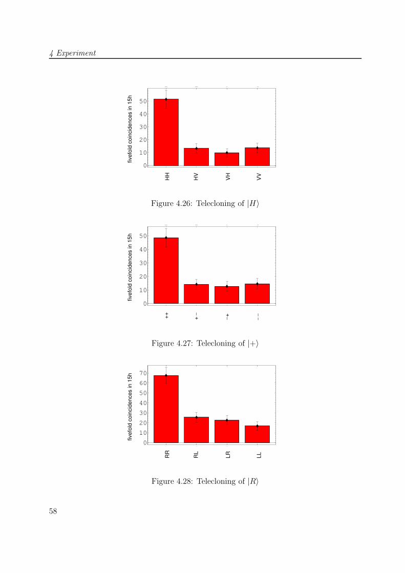
4 Experiment
1 2 3 40
10
20
30
40
50
1 2 3 4
HH
HV
VH
VV
fivef
old
coin
cide
nces
in 1
5h
Figure 4.26: Telecloning of |H〉
1 2 3 40
10
20
30
40
50
1 2 3 4
++ +
_
_ _
_+
fivef
old
coin
cide
nces
in 1
5h
Figure 4.27: Telecloning of |+〉
1 2 3 40
10
20
30
40
50
60
70
1 2 3 4
fivef
old
coin
cide
nces
in 1
5h
RR
RL
LR LL
Figure 4.28: Telecloning of |R〉
58
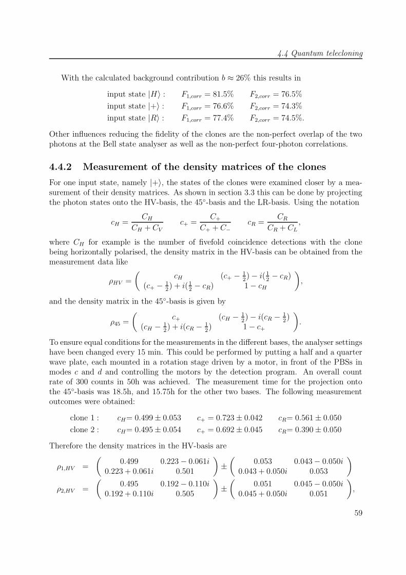
4.4 Quantum telecloning
With the calculated background contribution b ≈ 26% this results in
input state |H〉 : F1,corr = 81.5% F2,corr = 76.5%
input state |+〉 : F1,corr = 76.6% F2,corr = 74.3%
input state |R〉 : F1,corr = 77.4% F2,corr = 74.5%.
Other influences reducing the fidelity of the clones are the non-perfect overlap of the twophotons at the Bell state analyser as well as the non-perfect four-photon correlations.
4.4.2 Measurement of the density matrices of the clones
For one input state, namely |+〉, the states of the clones were examined closer by a mea-surement of their density matrices. As shown in section 3.3 this can be done by projectingthe photon states onto the HV-basis, the 45◦-basis and the LR-basis. Using the notation
cH =CH
CH + CVc+ =
C+
C+ + C−cR =
CRCR + CL
,
where CH for example is the number of fivefold coincidence detections with the clonebeing horizontally polarised, the density matrix in the HV-basis can be obtained from themeasurement data like
ρHV =
(cH (c+ − 1
2)− i(1
2− cR)
(c+ − 12) + i(1
2− cR) 1− cH
),
and the density matrix in the 45◦-basis is given by
ρ45 =
(c+ (cH − 1
2)− i(cR − 1
2)
(cH − 12) + i(cR − 1
2) 1− c+
).
To ensure equal conditions for the measurements in the different bases, the analyser settingshave been changed every 15 min. This could be performed by putting a half and a quarterwave plate, each mounted in a rotation stage driven by a motor, in front of the PBSs inmodes c and d and controlling the motors by the detection program. An overall countrate of 300 counts in 50h was achieved. The measurement time for the projection ontothe 45◦-basis was 18.5h, and 15.75h for the other two bases. The following measurementoutcomes were obtained:
clone 1 : cH= 0.499± 0.053 c+ = 0.723± 0.042 cR= 0.561± 0.050
clone 2 : cH= 0.495± 0.054 c+ = 0.692± 0.045 cR= 0.390± 0.050
Therefore the density matrices in the HV-basis are
ρ1,HV =
(0.499 0.223− 0.061i
0.223 + 0.061i 0.501
)±(
0.053 0.043− 0.050i0.043 + 0.050i 0.053
)
ρ2,HV =
(0.495 0.192− 0.110i
0.192 + 0.110i 0.505
)±(
0.051 0.045− 0.050i0.045 + 0.050i 0.051
),
59

4 Experiment
and in the 45◦-basis they are given by
ρ1,45 =
(0.723 −0.001 + 0.061i
−0.001− 0.061i 0.277
)±(
0.043 0.053 + 0.050i0.053 + 0.050i 0.043
)
ρ2,45 =
(0.692 −0.005− 0.110i
−0.005 + 0.110i 0.308
)±(
0.045 0.051 + 0.050i0.051 + 0.050i 0.045
).
As an illustration all matrices are plotted in Figs. 4.29 to 4.32. They have the threeimportant properties of normalisation, Hermiticity and positivity, therefore no maximumlikelihood estimation (see section 3.3) is necessary. For the input state |+〉 the fidelities ofthe clones are given by c+, thus
F1 = 72.33%± 4.25% F2 = 69.22%± 4.51%.
Again both fidelities are above the classical limit given by 66.67%. As shown in section 2.6the theoretical density matrices are given by
ρHV =
(0.5 0.333
0.333 0.5
)and ρ45 =
(0.833 0
0 0.167
).
The fidelities of the measured states to the theoretical state are 99.15% for clone 1 and98.60% for clone 2. This good result is due to the fact that the background events aremainly white noise, which means that they produce every measurement result with thesame probability 1
2. Though this lowers the fidelity to the input state, it doesn’t change
the measurement results in the HV- and RL-basis where the theory predicts cH = cR = 0.5.
60

4.4 Quantum telecloning
0
0.25
0.5
0.75
1
V
H
H
V
0
0.25
0.5
0.75
1
V
H
H
V
Figure 4.29: Real (left) and imaginary (right) part of the density matrix of clone 1 in theHV-basis
0
0.25
0.5
0.75
1
−+
+
− 0
0.25
0.5
0.75
1
−+
+
−
Figure 4.30: Real (left) and imaginary (right) part of the density matrix of clone 1 in the45◦-basis
61
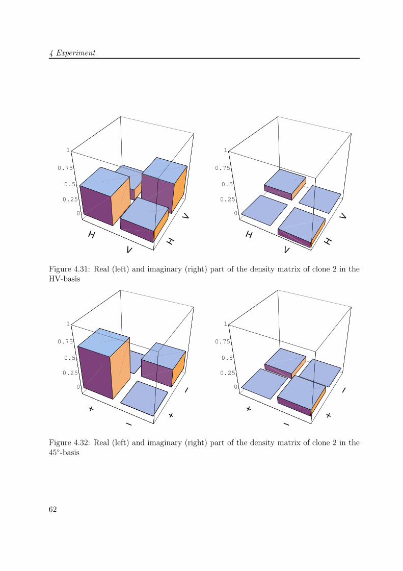
4 Experiment
0
0.25
0.5
0.75
1
V
H
H
V
0
0.25
0.5
0.75
1
V
H
H
V
Figure 4.31: Real (left) and imaginary (right) part of the density matrix of clone 2 in theHV-basis
0
0.25
0.5
0.75
1
−+
+
− 0
0.25
0.5
0.75
1
−+
+
−
Figure 4.32: Real (left) and imaginary (right) part of the density matrix of clone 2 in the45◦-basis
62
5 Summary
Quantum telecloning of three different polarisation states of photons was performed suc-cesfully within the scope of this thesis. For all input states, where we chose the threecomplementary polarisation directions |H〉, |+〉 and |R〉, a fidelity of the telecloned statesto the input states of about 70% could be achieved. This means that we could realise auniversal quantum cloning process, in which the cloned states were communicated to twodistant receivers simultaneously. It is universal since it shows equal performance for allkinds of input states, and quantum since the fidelities lie above the classical limit of 66.7%,which is the highest fidelity achievable by a measurement on the input state.For the implementation of the scheme a four-photon polarisation entangled state was usedwhich we could obtain with high visibility from parametric down conversion, and the inputstate was realised by the polarisation of a strongly attenuated laser beam. The necessaryinterference between the weak coherent state and one of the down conversion photons wasaligned by utilizing a two photon interference effect, the so called Hong Ou Mandel dip[16].Before the experimental quantum telecloning was started, quantum teleportation of thesame kind of input states was performed. This could be realised with the same experi-mental setup, just by using first order down conversion emissions instead of second orderemissions, for which the countrates are much higher. In this way the setup could be opti-mised for the subsequent long time measurements. The fidelities for the teleportation ofthe input states |H〉 and |V 〉 were about 92%, and about 86% for the input states |+〉 and|−〉. This assymetry was due to a particular setup of the Bell state analyser which reducedthe background contributions for the teleportation of |H〉 and |V 〉.Background contributions also posed the main difficulty for the realisation of quantumtelecloning. They were expected to constitute about 26% of the overall countrate whichmeans that there was little room left for our goal to exceed the classical limit for the qualityof the clones.After the universality of the process was proven, we chose one input state, namely |+〉 forwhich we studied the states of the copies in more detail by measuring their density matri-ces. The fidelity of the measured states to the output states predicted by theory were about99%. The same measurement can be extended to a measurement of the two-photon stateof both copies. As shown in the theory chapter those two photons should be entangled,and the hope is to verify this entanglement experimentally in the near future.

5 Summary
64
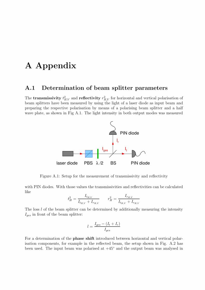
A Appendix
A.1 Determination of beam splitter parameters
The transmissivity t2H.V and reflectivity r2H,V for horizontal and vertical polarisation of
beam splitters have been measured by using the light of a laser diode as input beam andpreparing the respective polarisation by means of a polarising beam splitter and a halfwave plate, as shown in Fig A.1. The light intensity in both output modes was measured
gesI
Ir
It
λ /2
PIN diode
PIN diodelaser diode PBS BS
Figure A.1: Setup for the measurement of transmissivity and reflectivity
with PIN diodes. With those values the transmissivities and reflectivities can be calculatedlike
t2H =ItH,V
ItH,V + IrH,Vr2H =
IrH,VItH,V + IrH,V
The loss l of the beam splitter can be determined by additionally measuring the intensityIges in front of the beam splitter:
l =Iges − (It + Ir)
Iges
For a determination of the phase shift introduced between horizontal and vertical polar-isation components, for example in the reflected beam, the setup shown in Fig. A.2 hasbeen used. The input beam was polarised at +45◦ and the output beam was analysed in
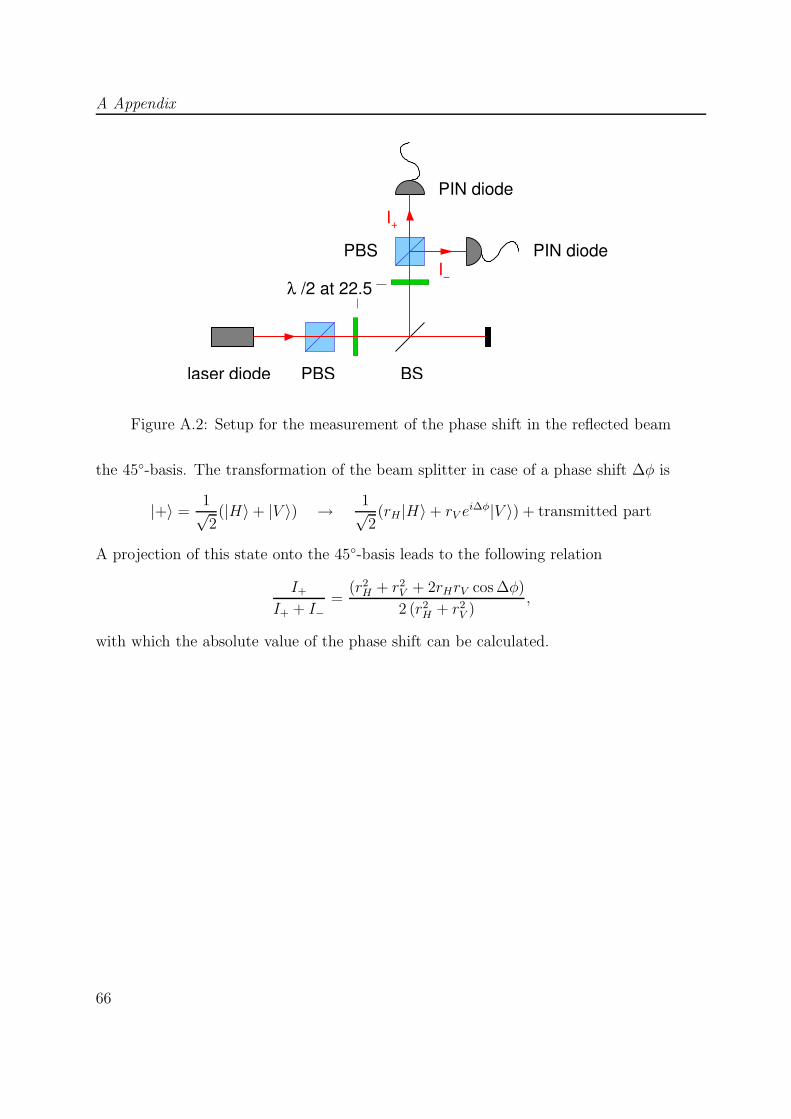
A Appendix
/2 at 22.5λ
PBS
I
I−
+
PIN diode
PIN diode
PBSlaser diode BS
Figure A.2: Setup for the measurement of the phase shift in the reflected beam
the 45◦-basis. The transformation of the beam splitter in case of a phase shift ∆φ is
|+〉 =1√2
(|H〉+ |V 〉) → 1√2
(rH |H〉+ rV ei∆φ|V 〉) + transmitted part
A projection of this state onto the 45◦-basis leads to the following relation
I+
I+ + I−=
(r2H + r2
V + 2rHrV cos ∆φ)
2 (r2H + r2
V ),
with which the absolute value of the phase shift can be calculated.
66

A.2 Representations of photon states
A.2 Representations of photon states
In this thesis two different representations of multi photon states have been used:
• If all photons occupy different modes, which means that they are distinguishable, justthe polarisation and spatial modes of the single photons are indicated, for example
|HVHV 〉abcd = |H〉a|V 〉b|H〉c|V 〉d
means that the photon in mode a is horizontally polarised, etc.
• If there can be more than one photon in a single mode, the photon number represen-tation is used, where the occupation numbers of the different modes are given, forexample
|2Ha, 1Vb〉means two photons with horizontal polarisation in mode a and one photon withvertical polarisation in mode b. The above state written as photon number statewould give
|HVHV 〉abcd = |1Ha, 1Vb, 1Hc, 1Vd〉.In some cases, where all photons have the same polarisation, the letters indicatingthe polarisation have been omitted, like
|0〉a|2〉b.
Those photon number states are also called Fock states.
67
Bibliography
[1] M. Murao, D. Jonathan, M. B. Plenio, and V. Vedral, Quantum telecloning and mul-tiparticle entanglement Phys. Rev. A 59, 156 (1999).
[2] N. Gisin and S. Massar, Optimal Quantum Cloning Machines Phys. Rev. Lett. 79,2153 (1997).
[3] Charles H. Bennett, Gilles Brassard, Claude Crepeau, Richard Josza, Asher Peres,and William K. Wooters, Teleporting an Unknown Quantum State via Dual Classicaland Einstein-Podolski-Rosen Channels, Phys. Rev. Lett. 70, 1895 (1993).
[4] Dik Bouwmeester, Jian-Wei Pan, Klaus Mattle, Manfred Eibl, Harald Weinfurter andAnton Zeilinger, Experimental quantum teleportation, Nature 390, 575 (1997).
[5] Dagmar Bruß, Artur Ekert, and Chiara Macchiavello, Optimal Universal QuantumCloning and State Estimation, Phys. Rev. Lett. 81, 2598 (1998).
[6] Dagmar Bruß and Chiara Macchiavello, On the entanglement structure in quantumcloning, quant-ph/0212059.
[7] Paul G. Kwiat, Klaus Mattle, Harald Weinfurter, and Anton Zeilinger, New High-Intensity Source of Polarisation-Entangled Photon Pairs, Phys. Rev. Lett. 75, 4337(1995).
[8] Harald Weinfurter and Marek Zukowski, Four-photon entanglement from down-conversion, Phys. Rev. A 64, 010102-1 (2001).
[9] S. Gaertner, M. Bourennane, M. Eibl, C. Kurtsiefer, H. Weinfurter, High-fidelitysource of four-photon entanglement, Appl. Phys. B 77, 803 (2003).
[10] W. K. Wooters and W. H. Zurek, A single quantum cannot be cloned, Nature 299,902 (1982).
[11] V. Buzek and M. Hillery, Quantum copying: Beyond the no-cloning theorem, Phys.Rev. A 54, 1844 (1996).
[12] V. Buzek and M. Hillery, Universal Optimal Cloning of Qubits and Quantum Registers,in QCQC’98, LNCS 1509 edited by C. P. Williams, Springer-Verlag Berlin Heidelberg,235 (1999).
BIBLIOGRAPHY
[13] Charles H. Bennett, Stephen J. Wiesner, Communication via One- and Two-ParticleOperators on Einstein-Podolski-Rosen States, Phys. Rev. Lett. 69, 2881 (1992).
[14] Klaus Mattle, Harald Weinfurter, Paul G. Kwiat, and Anton Zeilinger, Dense Codingin Experimental Quantum Communication, Phys. Rev. Lett. 76, 4656 (1996).
[15] C. H. Bennett, G. Brassard and A. K. Ekert, Quantum Cryptography, Sci. Am. 267,50 (1992).
[16] C. K. Hong, Z. Y. Ou, and L. Mandel, Measurement of Subpicosecond Time Intervalsbetween Two Photons by Interference Phys. Rev. Lett. 59, 2044 (1987).
[17] J. G. Rarity and P. R. Tapster, Interference Between a Single Photon and a Super-position of Coherent States in Quantum Interferometrie, edited by F. De Martini, G.Denardo, and Y. Shih (VCH, Weinheim), 211 (1996).
[18] S. Massar and S. Popescu, Optimal Extraction of Information from Finite QuantumEnsembles, Phys. Rev. Lett. 74, 1259 (1995).
[19] Asher Peres, Separability Criterion for Density Matrices, Phys. Rev. Lett. 77, 1413(1996).
[20] M. Horodecki, P. Horodecki, R. Horodecki, Separability of mixed states: necessary andsufficient conditions, Phys. Lett. A 233, 1 (1996).
[21] H.Weinfurter, Experimental Bell-State Analysis Europhys. Lett. 25, 559 (1994).
[22] P. G. Kwiat, H. Weinfurter, Embedded Bell-state analysis, Phys. Rev. A 58, 2623(1998).
[23] Jian-wei Pan and Anton Zeilinger, Greenberger-Horne-Zeilinger-state analyser, Phys.Rev. A 57, 2208 (1998).
[24] S. Gaertner, C. Kurtsiefer, and H. Weinfurter, A fast and simple multi-channel photoncoincidence unit for quantum communication, to be published.
[25] David S. Kliger, James W. Lewis, Cora Einterz Randall, Polarised Light in Opticsand Spectroscopy, Academic Press (1990).
[26] Jean-Claude M. Diels, Joel J. Fontaine, Ian C. McMicheal, and Francesco Simoni,Control and measurement of ultrashort pulse shapes (in amplitude and phase) withfemtosecond accuracy, Applied Optics 24, 1270 (1985).
[27] Axel Kasper, Erzeugung und Characterisierung ultrakurzer Lichtpulse aus Ti:SaLaser-Oszillatoren, Dissertation Technische Universitat Munchen (1997).
[28] N. Kiesel Experimental Analysis of a Three-Photon Entangled State, DiplomarbeitLMU Munchen (2002).
II
BIBLIOGRAPHY
[29] Danniel F. V. James, Paul G. Kwiat, William J. Munro, and Andrew G. White,Measurement of qubits, Phys. Rev. A 64, 052312 (2001).
[30] S. Gaertner, M. Bourennane, C. Kurtsiefer, and H. Weinfurter, Experimental demon-stration of four party quantum secret sharing, to be published.
[31] A. Lamas-Linares, J. C. Howell and D. Bouwmeester, Stimulated emission ofpolarisation-entangled photons, Nature 412, 887 (2001).
[32] Antia Lamas-Linares, Christoph Simon, John C. Howell, Dik Bouwmeester, Experi-mental Quantum Cloning of Single Photons, Science 296, 712 (2002).
[33] S. Gaertner, M. Bourennane, C. Kurtsiefer, H. Weinfurter, Multiphoton entanglementfrom parametric down conversion, to be published.
[34] Thomas Jennewein, Synchrone Erfassung von Photodetectionen an entfernten Orten,Diplomarbeit Universitat Innsbruck (1997).
[35] Harald Weinfurter, Quantum communication with entangled photons, Advances inatomic, molecular, and optical physics 42, 489 (2000).
[36] Charles Bennett and David P. DiVincenzo, Quantum information and computation,Nature 404, 247 (2000).
III

Acknowledgements
There are some people whom I would like to specially thank at this occasion.Harald Weinfurter for giving me the possibility of performing such an exciting experiment,and for offering some helpful advices and discussions. He also gave me the opportunity toattend conferences where I could gain some insight into recent fields of research.Christian Kurtsiefer for his permanent support and some useful hints which helped to safedays of work.His leaving to Singapur was a real loss.Many thanks to Sascha Gaertner for introducing me to the lab work, guiding me throughthe experiment, supporting me whenever needed and, most important, motivating andinspiring me, and helping me not to get frustrated sometimes. With him even hard workcould be real fun.Finally I want to thank my parents for supporting me in all the years of my studies.
Erklarung
Hiermit erklare ich, dass ich die vorliegende Arbei selbstandig und unter ausschließlicherVerwendung der angegebenen Quellen und Hilfsmittel verfasst habe.
Julia LauMunchen, den 16. Februar 2002