Embed Size (px)
Citation preview
Thirteenth International Symposium on Space Terahertz Technology, Harvard University, March 2002.
Quantum-limited Mixing in a Transformer-coupled
SIS Resonator for the 600 GHz Frequency Band
Cheuk-yu Edward Tong, Raymond Blundell
Harvard-Smithsonian center for Astrophysics, 60 Garden Street, Cambridge, MA 02138.
Krikor G Megerian, Jeffrey A. Stern, Henry G LeDuc
Jet Propulsion Lab, California Institute of Technology, 4800 Oak Grove Drive, Pasadena, CA 91109.
Abstract
Quantum-limited mixer noise temperature has been achieved in
Superconductor-Insulator-Superconductor (SIS) resonant mixer in the 600 — 720
GHz frequency range. Our mixer employs a single full-wave Nb/A1N/Nb tunnel
junction resonator, fed by a quarter-wave transformer. The devices have low critical
current density (-5 kA/cm2). The mixers were tested in a fixed-tuned waveguide
mixer mount. Double-side-band receiver noise temperatures equivalent to a few
quanta have been measured for a number of different devices. Using a 0.55 x 25 Inn
resonator, a noise temperature of 141 K was recorded at an LO frequency of 700 GHz
with the mixer at 4.2 K. The noise temperature dropped to 111 K when the helium
bath was pumped down to 2.8 K. High sensitivity has attained over reasonably wide
RF bandwidth, —17%. The IF bandwidth of these mixers has also been investigated.
I. Introduction
The introduction of distributed mixing in Superconductor-Insulator-Superconductor
(SIS) junctions is an important development in low-noise receiver technology for
sub-millimeter wavelengths [1,2]. The earliest distributed mixers employed fairly long
superconducting tunnel junctions, about 2 wavelengths long. The long junction acts as a
lossy transmission line in which mixing occurs along the whole length of the line. This class
of receiver has demonstrated sensitivities close to the quantum limit. A noise temperature of
s
TunnelRanier
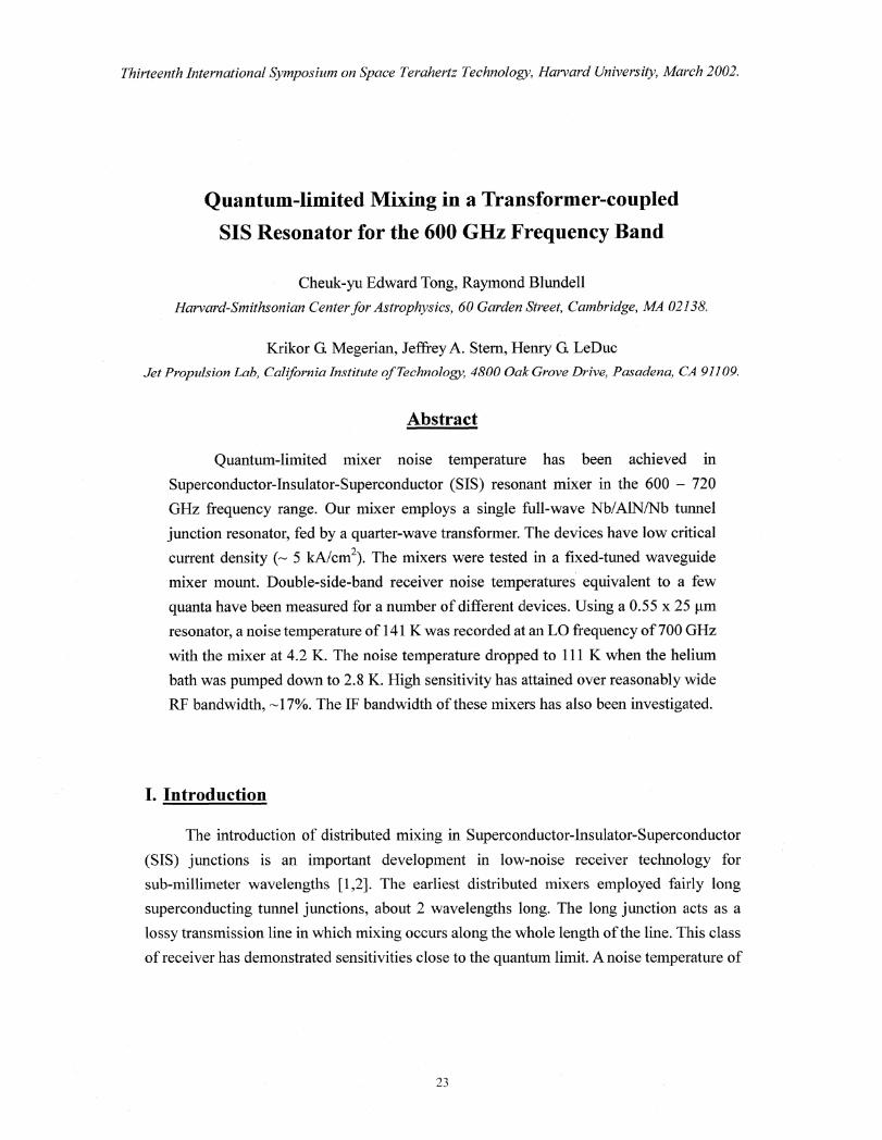
Fig. 1 Cross-sectional view of an
SIS non-linear transmission line. In
our mixers, the tunnel barrier is
Aluminum Nitride (A1N) and the
dielectric layer is 250 nm thick of
Silicon Oxide (Si0). The width of
the wiring layer, Ws is 4 pm.
Thirteenth international Symposium on Space Terahertz Technology, Harvard University, March 2002.
3hv/k was recorded at 460 GHz [1], where hv is the photon energy and k is the Boltzmann
constant.
In a subsequent developemnt, Belitsky [3] proposed that distributed mixing could also
be implemented in SIS resonators. One advantage of resonant distributed mixing is that the
resonator can achieve a higher impedance level compared to simple long superconducting
transmission lines which generally have very low characteristics impedance. Uzawa [4]
performed experiments with resonant distributed mixers incorporating a niobium nitride SIS
resonator in the 800 GHz frequency band. Finally, in 2001, Matsunaga [5] implemented
distributed mixing using dual SIS resonators connected in series through impedance
transformers, employing standard Nb/Al/A10x/Nb SIS junctions fabricated with optical
lithography. That mixer exhibited high sensitivity, with a measured noise temperature of 185
K at 630 Gfiz.
Following this encouraging result, we have developed resonant mixers based on
1\113/A1NiNb junctions fabricated with electron-beam lithography at Jet Propulsion Lab. In
this paper, we demonstrate that the sensitivity of 0.6 IIM wide full-wave SIS resonators can
reach quantum-limited performance in the 600 GHz band, at frequencies that approach the
band gap frequency of niobium.
II. Modeling of the SIS Resonator
Fig. 1 shows the cross-section of the SIS
non-linear transmission line, which reduces to a
simple microstrip line when the width of the
tunnel barrier, WI , is zero. Such a linear
superconducting microstrip line can readily be
modeled by various approaches. We have
employed the analysis described in [6], using
frequency dependent surface impedances from
the Mattis-Bardeen Theory [7]. Let Zo and yo be
the characteristics impedance and complex
propagation constant of the line respectively for
Wj = O. If W much smaller than the width of top
conductor of the microstrip, Ws, we can write
down the per unit length series impedance of the
24

- —0-- Slow Wave Factor
Thirteenth international Symposium on Space Terahertz Technology, Harvard University, March 2002.
transmission line as:
Wj/Ws),
and the per unit length parallel admittance as:
s
J-F-j co.0 s ,YV + 1? A
fj 1/T7
where Gp is the specific capacitance of the tunnel junction per unit area, RNA is the product
of normal state resistance and area of the junction and is a signal mixing factor. In equation
(2), the second term represents the contribution of the geometrical capacitance of the tunnel
junction and the third term represents the mixing conductance due to the tunneling
quasiparticle current, Gqi, [3].
From Tucker's quantum theory of mixing [8], we can write down an expression for
= G R
N
= N .n
[
jn2 (a\ J" 1
2
)//de (VO
nhv
(3)el?
qP2hv j=--co
where a = eVLol hv is the normalized voltage impressed by the Local Oscillator (LO) across
the junction, Id(V) is the DC
current-voltage characteristic of the 6
junction and Vo is the DC bias voltage5
at the operating point. From our
simulation, we fmd that a niobium 4
based SIS resonator should operate3
well with a — 0.7 and Vo — 1.5 mV for v\
— 660 GHz. Under these conditions, 2 ................ ...................................................... 1
equation (3) gives — 0.8. By assigning5
.a
Characteristic Impeda constant value to we assume that
the distributed mixer may be described 00.2 0.4 0.6 0.8 1 1.2 1.4
by a linear model [1]. Width of Tunnel Barrier Wj (bun)
Once Zs, and Yp, are known, we canFig. 2 Variation of Characteristic Impedance, 4,
evaluate the key parameters of theand Slow Wave Factor, 20/4, as a function of 14;
non-linear transmission line, including for our mixers at a frequency of 660 GHz. We havethe characteristic impedance, Z e , the taken W. 4 gm, C = 65 jF/gm2 and RNA = 40 12
2complex propagation constant, y, and m.
the guided wavelength, 2g .
30
25
20
15
25
15
- Vij = 0.5= 0.6......
?
I lc\
e
.L.
- \ _
yA t:
I \ -‘
10 15 20 25 30
5
0
-5
0 5 10 15 20 25 30
Length ofResonator
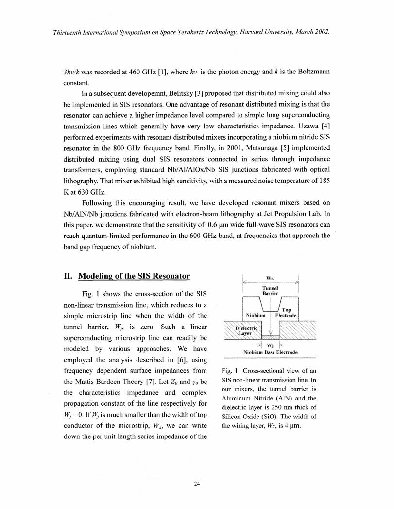
Fig. 3 Input impedance of SIS Resonator at 660 GHz as a
function of resonator length for W 0.5, 0.6 and 0.7 gm. Rin
is the real part and X. is the imaginary part of the inputimpedance, where Rir, +jXm= Z,(Wi ).coth (y(W.d.L) and Lis the length of the resonator.
10
L_
Thirteenth international Symposium on Space Terahertz Technology, Harvard University, March 2002.
Z, ./Yp
=
= .Im(y)g 27r (6)
The characteristic impedance and the slow wave factor, 2 0/2g , for our mixer as a function of
the width of the tunnel barrier, W3 , are plotted in Fig. 2. From the figure, it can be seen that
is not a strong function of Wi for W3 > 0.4 pm. However, 2gis strongly dependent on the
width of the tunnel junction.
(4)
(5)
In fig. 3 we display the
input impedances of 3 SIS
resonators with different
junction widths. The length
for half-wave resonance is
about 12 pm and full-wave
resonance occurs around 25
gm. As discussed above, the
resonant impedance level is
not a strong function of
However, for a given length
of resonator, the resonant
frequency is quite sensitive
to the junction width.
In our experiments, we
have chosen to work with
full-wave resonators rather
than half-wave resonators
because the value of &Yin/ df
is smaller at full-wave
resonance, hence a larger
impedance bandwidth can
be achieved.
26
,
'A:MrFeed point of
W aveguide Em beddingCircuit
k3
35
Thirteenth international Symposium on Space Terahertz Technoloo), Harvard University, March 2002.
III. Mixer and Receiver Design
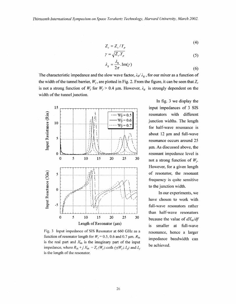
In order to match the low input resistance (-6 I -2) at the full-wave resonance of the
non-linear SIS resonator, we use a 3 filll wide niobium microstrip transformer section to
couple the signal power from our fixed-tuned waveguide mixer mount [9,10]. The layout of
the center of the mixer chip is shown in Fig. 4. Since the resonant frequency is highly
dependent on the exact width of the junction, we have fabricated chips with different
junction widths and lengths about the nominal dimensions of 0.6 x 25 pin. We had a target
current density of 5 kA/cm2, which corresponds to RNA = 40 S2 gm2.
The mixer is tested in a laboratory test dewar, the details of which have been described
elsewhere [5,11]. In all the experiments, we have used an IF center frequency of 3 GHz and
the signal and LO input to the &war are combined using a wire grid polarizer as a beam
splitter in front of the cryostat vacuum window The receiver IF output is measured by a
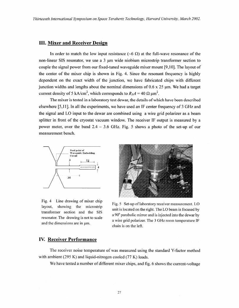
power meter, over the band 2.4 — 3.6 GHz. Fig. 5 shows a photo of the set-up of our
measurement bench.
Fig. 4 Line drawing of mixer chip
layout, showing the microstriptransformer section and the SIS
resonator. The drawing is not to scale
and the dimensions are in gm.
Fig. 5 Set-up of laboratory receiver measurement. LO
unit is located on the right. The LO beam is focused by
a 900 parabolic mirror and is injected into the dewar bya wire grid polarizer. The 3 GHz room temperature IFchain is on the left.
Iv. Receiver Performance
The receiver noise temperature of was measured using the standard Y-factor method
with ambient (295 K) and liquid-nitrogen cooled (77 K) loads.
We have tested a number of different mixer chips, and fig. 6 shows the current-voltage
27
0
LE",
-71
2.25
2
1.75
1.5
1.25
1
Thirteenth International Symposium on Space Terahertz Technology, Harvard University, March 2002.
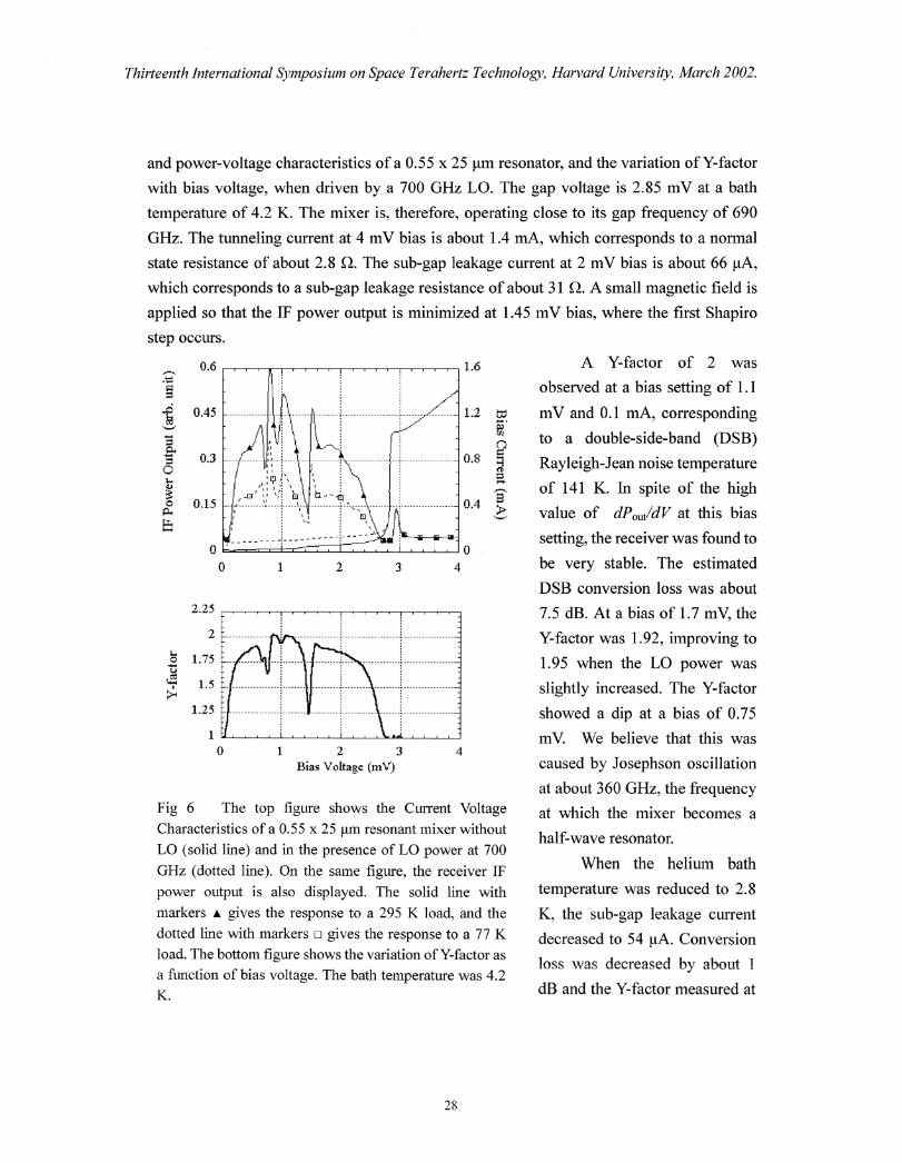
and power-voltage characteristics of a 0.55 x 25 gm resonator, and the variation of Y-factor
with bias voltage, when driven by a 700 GHz LO. The gap voltage is 2.85 mV at a bath
temperature of 4.2 K. The mixer is, therefore, operating close to its gap frequency of 690
Gflz. The tunneling current at 4 mV bias is about 1.4 mA, which corresponds to a normal
state resistance of about 2.8 a The sub-gap leakage current at 2 mV bias is about 66 gA,
which corresponds to a sub-gap leakage resistance of about 31 a A small magnetic field is
applied so that the IF power output is minimized at 1.45 mV bias, where the first Shapiro
step occurs.
0.6
0.45
0.3
0.15
3
1 2 3 4Bias Voltage (mV)
Fig 6 The top figure shows the Current Voltage
Characteristics of a 0.55 x 25 jm resonant mixer without
LO (solid line) and in the presence of LO power at 700
GHz (dotted line). On the same figure, the receiver IF
power output is also displayed. The solid line withmarkers A gives the response to a 295 K load, and the
dotted line with markers u gives the response to a 77 K
load. The bottom figure shows the variation of Y-factor as
a function of bias voltage. The bath temperature was 4.2K.
A Y-factor of 2 was
observed at a bias setting of 1.1
mV and 0.1 mA, corresponding
to a double-side-band (DSB)
Rayleigh-Jean noise temperature
of 141 K. In spite of the high
value of dP out/dV at this bias
setting, the receiver was found to
be very stable. The estimated
DSB conversion loss was about
7.5 dB. At a bias of 1.7 mV, the
Y-factor was 1.92, improving to
1.95 when the LO power was
slightly increased. The Y-factor
showed a dip at a bias of 0.75
mV. We believe that this was
caused by Josephson oscillation
at about 360 GHz, the frequency
at which the mixer becomes a
half-wave resonator.
When the helium bath
temperature was reduced to 2.8
K, the sub-gap leakage current
decreased to 54 gA. Conversion
loss was decreased by about 1
dB and the Y-factor measured at
28
720600 620 640 660 680 700
L.O. Frequency (Gliz)
250
a 200tt.ta) `d,
4t`dg.— —
31117k— 54:1111
150
a)
•100 - - - -
0
C.t)r2) 50 ...........
0
**ti
A
m.V. bias (4.2 K bath)--*— 1.7 n1\1 bias (4.2 Kbath)
ITN bias (2.8 K bath)
.150
100
200
et
50 1::10.60 x 24 Resonator0 0.60 x 23 Resonator
-A- 0. 5 5 x 25 Resonator
0580 600 620 640 660 680 700 720
LO Frequency (GHz)
250
Thirteenth International Symposium on Space Terahertz Technology, Harvard University, March 2002.
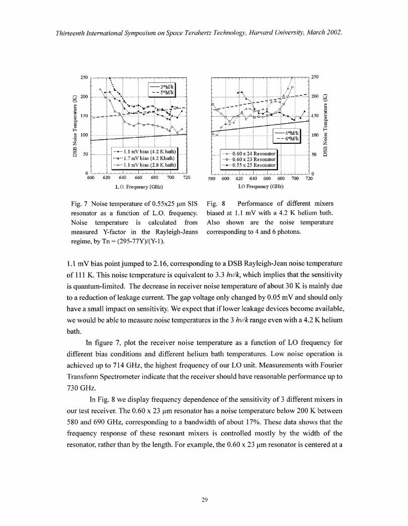
Fig. 7 Noise temperature of 0.55x25 inn SIS
resonator as a function of L.O. frequency.
Noise temperature is calculated from
measured Y-factor in the Rayleigh-Jeans
regime, by Tn (295-77Y)/(Y-1).
Fig. 8 Performance of different mixers
biased at 1 A mV with a 4.2 K helium bath.
Also shown are the noise temperature
corresponding to 4 and 6 photons.
1.1 mV bias point jumped to 2.16, corresponding to a DSB Rayleigh-Jean noise temperature
of 111 K. This noise temperature is equivalent to 3.3 hvfic, which implies that the sensitivity
is quantum-limited. The decrease in receiver noise temperature of about 30 K is mainly due
to a reduction of leakage current. The gap voltage only changed by 0.05 mV and should only
have a small impact on sensitivity. We expect that if lower leakage devices become available,
we would be able to measure noise temperatures in the 3 hv/1c range even with a 4.2 K helium
bath.
In figure 7, plot the receiver noise temperature as a function of LO frequency for
different bias conditions and different helium bath temperatures. Low noise operation is
achieved up to 714 GHz, the highest frequency of our LO unit. Measurements with Fourier
Transform Spectrometer indicate that the receiver should have reasonable performance up to
730 GHz.
In Fig. 8 we display frequency dependence of the sensitivity of 3 different mixers in
our test receiver. The 0.60 x 23 lam resonator has a noise temperature below 200 K between
580 and 690 GHz, corresponding to a bandwidth of about 17%. These data shows that the
frequency response of these resonant mixers is controlled mostly by the width of the
resonator, rather than by the length. For example, the 0.60 x 23 gm resonator is centered at a
29
240
A .................... 200
160 2072'
- - - 120
80
40A" AA A'',
0
AAA A
-2
IA Conversion LossSingle Pole Fit
-12
- Noise Temperature I
-10
4 5 6 7 8 9i03IF Frequency (GI-1z)
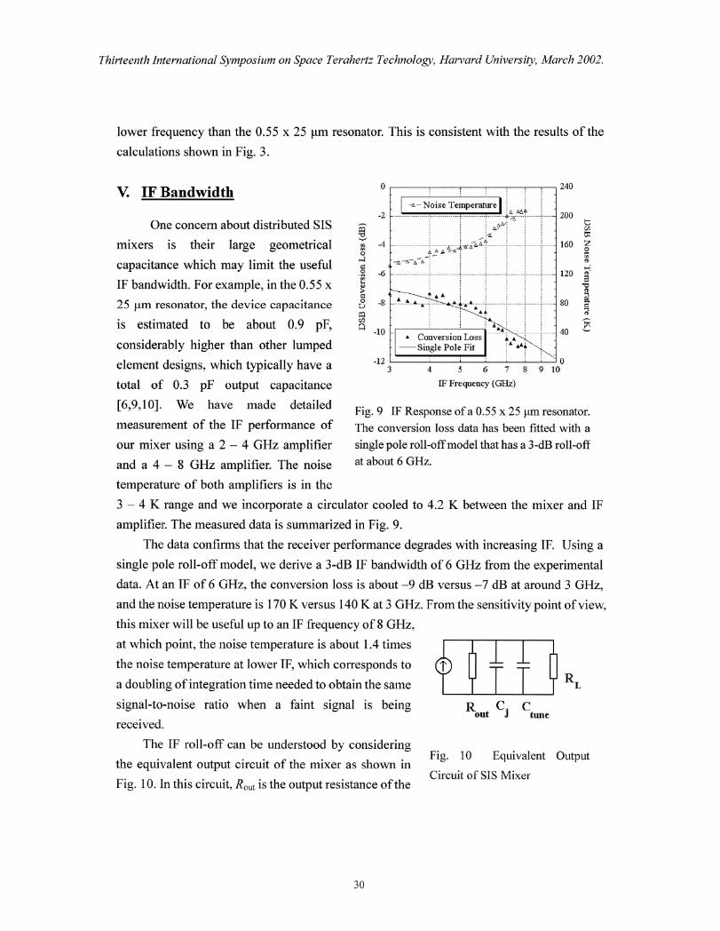
Fig. 9 IF Response of a 0.55 x 25 Im resonator.
The conversion loss data has been fitted with a
single pole roll-off model that has a 3-dB roll-off
at about 6 GHz.
R C. Cout J tune
Thirteenth International Symposium on Space Terahertz Technology, Harvard University, March 2002.
lower frequency than the 0.55 x 25 pm resonato . This is consistent with the results of the
calculations shown in Fig. 3.
V. IF Bandwidth
One concern about distributed SIS
mixers is their large geometrical
capacitance which may limit the useful
IF bandwidth. For example, in the 0.55 x
25 jim resonator, the device capacitance
is estimated to be about 0.9 pF,
considerably higher than other lumped
element designs, which typically have a
total of 0.3 pF output capacitance
[6,9,10]. We have made detailed
measurement of the IF performance of
our mixer using a 2 — 4 GHz amplifier
and a 4 — 8 GHz amplifier. The noise
temperature of both amplifiers is in the
3 — 4 K range and we incorporate a circulator cooled to 4.2 K between the mixer and IF
amplifier. The measured data is summarized in Fig. 9.
The data confirms that the receiver performance degrades with increasing IF. Using a
single pole roll-off model, we derive a 3-dB IF bandwidth of 6 GHz from the experimental
data. At an IF of 6 GHz, the conversion loss is about —9 dB versus —7 dB at around 3 GHz,
and the noise temperature is 170 K versus 140 K at 3 GHz. From the sensitivity point of view,
this mixer will be useful up to an IF frequency of 8 GHz,
at which point, the noise temperature is about 1.4 times
the noise temperature at lower IF, which corresponds to
a doubling of integration time needed to obtain the same
signal-to-noise ratio when a faint signal is being
received.
The IF roll-off can be understood by consideringFig. 10 Equivalent Output
the equivalent output circuit of the mixer as shown in
Fig. 10. In this circuit, R.u t is the output resistance of theCircu t of SIS Mixer
30

Thirteenth international Symposium on Space Terahertz Technology, Harvard University, March 2002.
device given by eirdI on the current-voltage characteristic of the device in the presence of
LO drive q is the junction capacitance and Ctune is any parasitic capacitance introduced by
any matching circuit. In the case of the resonant mixer, Ctune is introduced by the transformer
section and it is much smaller than Ci . Assuming that the mixer output is connected to a
constant load, RL , the 3-dB IF bandwidth as a result of this RC circuit can simply be written
as:
(1+ R011 )
RidF3 dB
2;r. Rout .1? L .(C1 C ,„,)
=
27r er .(RN A).(1+ x)C sp (7)
where r = Rout / R and x = r tune- I C In our mixer, RL = 50 K .2, Rout — 45 12 and x< < 1, and we— •
have F34B — 7.5 GHz. This is close to the fitted value of 6 GHz.
It is clear from equation (7) that when R,:xit — RL , the IF bandwidth limitation is imposed
not so much by the large junction capacitance but by a large value of r, the ratio between the
output resistance and the normal-state resistance. In this example, we have r > 10. However,
this seems unavoidable at high operating frequency where the quasi-particle tunneling step
is very wide and the step is more likely to be flat, giving rise to relatively high values of Rout
This does not seem to be unique to resonant mixers. We also note that the IF bandwidth
depends on the RNA product. Clearly, we may improve the IF bandwidth by increasing the
current density of the tunnel junction. However, at higher current density, GI, slowly
increases, so that the gain in bandwidth may be limited.
Equation (7) can be applied to all other types of SIS mixers. In many lumped element
mixer designs, the tuning circuit may involve a large capacitance, making x > 1, In which
case, equation (7) predicts that the IF bandwidth will be smaller than resonant mixers.
The above discussion assumes a constant IF load. An IF matching circuit can always be
designed to reduce the impact of the IF roll-off effect. The large geometrical capacitance of
the distributed mixer does not seem to impose a fundamental limit on the IF bandwidth of the
mixer.
VI. Conclusion
A near Quantum-limited sensitivity has been achieved in the 600 — 720 GHz frequency
band using an SIS resonant mixer receiver. The tunnel junction resonators in our mixer
design can be modeled easily through a simple linear transmission line equations. Using
transformer-coupled full wave Nb/A1N/Nlb resonators, we have measured noise
31
Thirteenth International Symposium on Space Terahertz Technology, Harvard University, March 2002.
temperatures as low as 141 K at 700 GHz with the mixer cooled to 4.2 K and 111 K with the
mixer cooled to 2.8 K. The mixers exhibit a 17% RF bandwidth, have a measured 3-dB IF
bandwidth of 6 GHz and useful sensitivities up to an IF bandwidth of about 8 GHz.
References
[1] C.E. Tong, R. Blundell, B. Bumble, J.A. Stem, and H.G. LeDuc, "Quantum-limited heterodyne
detection in superconducting nonlinear transmission lines at sub-millimeter wavelengths," Appl.
Phys. Lett., vol. 67, pp. 1304-1306, Aug. 1995.[2] C.E. Tong, L. Chen, and R. Blundell, "Theory of distributed mixing and amplification in a
superconducting quasi particle nonlinear transmission line," IEEE Trans. Microwave Theory
Tech., vol. 45, pp. 1086-1092, July 1997.
[3] YV Belitsky, and E.L. Kollberg, "Superconductor-insulator-superconductor tunnel strip line," J.
App!. Phys., vol. 80, pp. 4741-4748, 1996.
[4] Y Uzawa, A. Kawakami, S. Miki, and Z. Wang, "Performance of all-NbN quasi-optical SIS
mixers for the terahertz-band," IEEE Trans. Appl. Supercond, vol. 11, pp. 183-186, 2001.
[5] T. Matsunaga, C.E. Tong, T. Noguchi, R. Blundell, "Fabrication and characterization of a 600
GHz resonant distributed SIS junction for fixed-tuned waveguide receiver," Proc. 12th
Int. Symp.
Space THz Tech., pp. 571-580, I. Mehdi, ed, San Diego, CA, Feb. 2001.
[6] C.E. Tong, R. Blundell, S. Paine, D.C. Papa, J. Kawamura, X. Zhang, J.A. Stern, and H.G LeDuc,
"Design and characterization of a 250-350 GHz fixed-tuned Superconductor-Insulator-Super-
conductor receiver," IEEE Trans. Microwave Theory Tech., vol. 44, pp. 1548-1556, Sept. 1996.
[7] D.C. Mattis, and J. Bardeen, "Theory of the anomalous skin effect in normal and
superconducting metals," Phys. Rev., vol. 1 U, pp. 412- 418, July 1958.
[8] J.R. Tucker, and M.J. Feldman, "Quantum detection at millimeter wavelengths," Rev. Mod. Phys.,
vol. 57, pp. 1055-1113, Oct. 1985.[9] R. Blundell, C.E. Tong, D.C. Papa, R.L. Leombntno, X. Zhang, S. Paine, J.A. Stern, and H.G.
LeDuc, "A wideband fixed-tuned SIS receiver for 200 GHz operations," IEEE Trans.
Microwave Theory Tech., vol. 43, pp. 933-937, 1995.
[10] C.E. Tong, R. Blundell, D.C. Papa, J.W. Barrett, S. Paine, X. Zhang, J.A. Stem, and H.G. LeDuc,
"A fixed-tuned low noise SIS receiver for the 600 GHz frequency band," Proc. 6th Int. Symp.
Space THI Tech., pp. 295-304, J. Zmuidzinas, ed, Pasadena, CA, Mar. 1995.[11] J. Kawamura, R. Blundell, C.E. Tong, D.C. Papa, T.R. Hunter, S.N. Paine, F. Patt, G Gol'tsman,
S. Cherednichenko, B. Voronov, and E. Gershenzon, "Superconductive hot-electron-bolometer
mixer receiver for 800 GHz operation," IEEE Trans. Microwave Theory Tech., vol. 48, pp.683-689, 2000.
32


![Unconventional Superconductivity at Si(111)- H...superconductivity [14, 15]. Since the atomic-layer superconductors also have broken SIS, mixing of Cooper pairs could naturally occur](https://img.pdfslide.us/doc/110x75/5f0a3b5e7e708231d42aa666/unconventional-superconductivity-at-si111-h-superconductivity-14-15-since.jpg)