Embed Size (px)
Citation preview
Co-funded by the European Commission
TRAIN-ALLIntegrated System for driver Training and Assessment using Interactive
education tools and New training curricula for ALL modes of road transport
Contract no. 031517Common System Architecture for driving simulators based on interoperable federates
Deliverable No.: D2.1Dissemination Level PublicWorkpackage No. WP2 Workpackage Title Towards a Single Training and
Assessment PlatformActivity No. A2.1 Activity Title: Common System Architecture for
Driving Simulators Activity Leader: Roger Jansen (TNO)
Workpackage Leader Wim Huiskamp (TNO)Authors (per company, if more than one company provide it together)
Wim Huiskamp (TNO)Roger Jansen (TNO)Bart Kappe (TNO)
Richard Holzer (UP)Irène Mandsouris (ICCS)Philippe Vanhulle (THALES)
Status (Final; Draft; Revised Draft): Final File Name: TRAIN-ALL Deliverable 2.1_final.docProject start date and duration: 01 November 2006, 36 MonthsSubmission date: May 2008Version Number: V6Pages Number: 141Distribution EC, all partners
Co-funded by the European Commission
Version history
Version Date Modifications
1 April 2007 First version by TNO of the Deliverable ready. Draft circulated to partners for review.
2 September 2007Update by TNO. Answers to the Datamodel Questionnaire processed. Figure replaced by TNO. Added Federate code example, RTI table, and Conclusions.
3 November 2007 Removed former chapter 7
4 March 2008 Added results of task 2.2 and task 2.3
5 April 2008 Added sections 3.7 and 8.4, final version
6 May 2008 Final corrections by peer review inputs. Ready for submission
V6-Final Version - MayMay 2008 Page 2 of 140
TRAIN-ALL Deliverable 2.1contract no 031517
Co-funded by the European Commission
Table of Contents1.1 Towards a single Training and Assessment Platform 121.2 Common System Architecture for Distributed Interoperable Driving
Simulators 122.1 Architecture Requirements 142.2 Architecture Concept and Development Approach 142.3 Federation conceptual model 172.4 Demonstrator and Module descriptions 19
2.4.1 TRAIN-ALL demonstrators overview 192.4.2 TRAIN-ALL modules overview 20
2.5 Proposed HLA federation for TRAIN-ALL 223.1 Database Requirements 263.2 Database Concept 27
3.2.1 3D-Databases 273.2.2 Scenario’s 283.2.3 What is available? 293.2.4 Conclusion 29
3.3 Consistency of the DataBase when using it dynamically (WIVW) 304.1 Federate Information Exchange Requests 32
4.1.1 Driving Simulator Interface 334.1.2 Definition of the Federates 35
4.2 Data Representation 414.3 Data Distribution 424.4 HLA FOM Design 424.5 HLA Interface Design 434.6 TRAIN-ALL Federate Code Example 445.1 Identification rules 48
5.1.1 HLA RTI and identification 485.1.2 Convention about federation names 485.1.3 DIS identification 485.1.4 Federation identification 495.1.5 Federates identification 495.1.6 Objects identification for road driving 50
5.2 States 515.2.1 Federation state 515.2.2 Federate state 525.2.3 Information provided and/or required by each federate 52
5.3 Algorithms 535.3.1 Dead Reckoning introduction 535.3.2 Update policy for attribute values and Dead Reckoning 53
5.4 Coordinates systems 545.4.1 Geographical reference system 545.4.2 Entity reference system 545.4.3 Some representations 55
5.5 Curvilinear coordinate system 575.6 Protocols 58
5.6.1 Standard HLA 585.6.2 Federation Management 585.6.3 Declaration Management 59
V6-Final Version May Page 3 of 140
TRAIN-ALL Deliverable 2.1contract no 031517
Co-funded by the European Commission
5.6.4 Object Management 605.6.5 Ownership Management 615.6.6 Data Distribution Management 615.6.7 Time Synchronization 615.6.8 Data marshalling 62
5.7 Other considerations and versions 625.7.1 What could be the federation execution 625.7.2 Others federation considerations 635.7.3 Software versions 63
6.1 Survey of RTIs 646.1.1 Existing commercial and open source RTI 646.1.2 Implementation of the HLA RunTime Infrastructure 656.1.3 Survey of HLA Middleware tools 676.1.4 Main Results of the ARCOSIM-HLA study (July 2002) 68
6.2 Existing HLA Middleware tools among the TRAIN-ALL consortium 716.2.1 TNO-RCI Middleware 716.2.2 Thales’ NIET 1516 72
6.3 HLA tools description 726.4 Survey of tools 737.1 Training and assessment in a single simulator 747.2 Training and assessment on different simulators 757.3 Interoperability of CBT and simulation 767.4 Interoperability between ADAS/IVICS and simulators/ CBT tools 76
7.4.1 Introduction 767.4.2 Composition of the data frame 77
8.1 Current research 798.1.1 SAIC 808.1.2 Stottler Henke Associates 808.1.3 Boeing 818.1.4 Engineering and Computer Simulations 838.1.5 Intelligent Automation Inc. 85
8.2 TNO SimSCORM 858.3 SimSCORM and TRAIN-ALL 8810.1 TRAIN-ALL documents production 9010.2 Referenced Documents 90A1 Concepts of the High Level Architecture 93A2 The RTI services 94A3 The FEDEP Methodology 94B1: Some history 97B2: Evolution of the RPR-FOM 97C1 General Information 98C2 Initial Data 98C3 Runtime Data Input 99C4 Runtime Data Output 99C5 Evaluation Data 100C6 Interaction Exchange 100G1 Products Overview 105G2 TNO Simulation Architecture (TSA) 105
V6-Final Version May Page 4 of 140
TRAIN-ALL Deliverable 2.1contract no 031517
Co-funded by the European Commission
G3 TSA Framework 106G4 Run-time Communication Infrastructure (TSA-RCI) 106H1 SCORM Content Aggregation Model (CAM) 118H2 SCORM Content Model 119H3 SCORM Content Packaging 121H.4: SCORM Metadata 122H.5: SCORM sequencing and Navigation 124H.6: SCORM Run Time Environment 125
V6-Final Version May Page 5 of 140
TRAIN-ALL Deliverable 2.1contract no 031517
Co-funded by the European Commission
List of Figures
Figure 1: High Level Diagram of main TRAIN-ALL elements..............................................13
Figure 2: Generic HLA concept...........................................................................................15
Figure 3: Conceptual Object Model.....................................................................................18
Figure 4: TRAIN-ALL prototype federation..........................................................................23
Figure 5: Visualisation system representation in a Driving Simulator..................................25
Figure 6: DataBase interaction in a federation....................................................................26
Figure 7: Example of a generated synthetic roads network DataBase that needs handwork28
Figure 8: Interconnection of scenario environments and driver’s viewpoint........................30
Figure 9: Adaptive Training interface design.......................................................................39
Figure 10: Enhanced Reality interface design......................................................................40
Figure 11: HLA Interactions for Virtual Instructor and Debriefing federate...........................44
Figure 12: Alternative HLA Interactions for Virtual Instructor and Debriefing federate.........45
Figure 13: Federation state diagram.....................................................................................51
Figure 14: Federate state diagram........................................................................................52
Figure 15: Geocentric Cartesian Coordinate system.............................................................54
Figure 16: Entity coordinate system......................................................................................55
Figure 17: Rotate about z by angle Psi.................................................................................55
Figure 18: Rotate about y’ by Theta......................................................................................55
Figure 19: Rotate about x’’ by Phi..........................................................................................55
Figure 20: Representation of a line......................................................................................56
Figure 21: Representation of a surface................................................................................57
Figure 22: Object class publication and subscription............................................................59
Figure 23: Interaction class publication and subscription......................................................59
Figure 24: Object management.............................................................................................60
Figure 25: Interaction transmission........................................................................................61
Figure 26: HLA management effects conceptual model for exercise execution....................62
Figure 27: Code Generation based on the FOM or SOM......................................................71
Figure 28: NIET1516 library architecture..............................................................................72
Figure 29: CAN Message Formats........................................................................................77
Figure 30: Data Frame Format..............................................................................................78
Figure 31: GUI of the LMS.....................................................................................................82
Figure 32: LMS interfacing with Flight Sim............................................................................82
Figure 33: LMS integration....................................................................................................83
Figure 34: A schematic overview of an integration of a SCORM compliant LMS and the Delta3D simulation engine using smart client technology....................................85
V6-Final Version May Page 6 of 140
TRAIN-ALL Deliverable 2.1contract no 031517
Co-funded by the European Commission
Figure 35: TNO HLA-SCORM platform, where each SCO has its own HLA and LMS connection............................................................................................................86
Figure 36: Student SCO in Moodle, presenting a 3D visualization and control of an HLA compliant driving simulator...................................................................................87
Figure 37: Top-level view of the FEDEP...............................................................................95
Figure 38: Detailed view of the FEDEP.................................................................................96
Figure 39: TNO Simulation Architecture (TSA) supporting HLA applications......................105
Figure 40: Runtime Communication Infrastructure..............................................................106
Figure 41: Federate Manager Component (GUI)................................................................108
Figure 42: The layered RTI design......................................................................................109
Figure 43: Assets are the building blocks of a learning resource........................................119
Figure 44: A Sharable Content Object (SCO), the smallest learning resource that can be addressed by a learning management system...................................................120
Figure 45: Students perform learning activities, which can consist of one or more SCOs, Assets or sub Activities.......................................................................................120
Figure 46: Conceptual illustration of a content organization, the structured map of activities that the students perform in a lesson or course.................................................121
Figure 47: The SCORM content package, with a manifest file describing the content in detail122
Figure 48: Activity tree.........................................................................................................124
Figure 49: Interface between RTE and LMS.......................................................................126
Figure 50: The top-level of the MSDL schema, containing the main elements...................130
Figure 51: Plan....................................................................................................................131
Figure 51: A Course of Action sub element structure..........................................................132
Figure 53: the Decision Support Matrix...............................................................................133
Figure 54: Trigger................................................................................................................134
Figure 55: Triggering Event.................................................................................................135
Figure 56: Friendly (Triggering) Event.................................................................................136
Figure 57: Threat (Triggering) Event...................................................................................136
Figure 58: Enemy (Triggering) Event..................................................................................137
Figure 59: Movement (Triggering) Event.............................................................................138
Figure 60: COA phases.......................................................................................................139
Figure 61: Events.................................................................................................................140
Figure 62: Unit activities......................................................................................................140
Figure 63: Event Threat Activity...........................................................................................141
V6-Final Version May Page 7 of 140
TRAIN-ALL Deliverable 2.1contract no 031517
Co-funded by the European Commission
List of Tables
Table 1: FEDEP version IEEE 1516.3....................................................................................16
Table 2: TRAIN-ALL proposed demonstrators and modules..................................................19
Table 3: Demonstrators and use of federates.........................................................................23
Table 4: Runtime data output by FOERST simulator..............................................................34
Table 5: Runtime data output by FOERST simulator (meta-information example)................35
Table 6: GADGET Matrix levels..............................................................................................36
Table 7: Categories of driver misbehaviour, Level1................................................................36
Table 8: Categories of driver misbehaviour, Level2................................................................37
Table 9: Categories of driver misbehaviour, Level3................................................................38
Table 10: HLA services used by TRAIN-ALL federates..........................................................43
Table 11: Sample of code generated by the RCI Code Generator.........................................45
Table 12: Sample of the Virtual Instructor federate code........................................................46
Table 13: Federates identification (ToolIDmoduleID).............................................................49
Table 14: Attributes of the grid................................................................................................57
Table 15: Services that are required in the simulation............................................................58
Table 16: Software versions...................................................................................................63
Table 15: Existing RTI commercial licence.............................................................................64
Table 16: Existing RTI open source licence............................................................................64
Table 17: RTI market production ([2TRAIN])..........................................................................65
Table 20: Performance of RTIs analysis.................................................................................70
Table 21: Commercial HLA Middleware and Tools.................................................................73
Table 20: TRAIN-ALL documents production.........................................................................90
Table 21: Referenced Documents..........................................................................................90
Table 24: the 10 HLA-Rules....................................................................................................93
Table 25: RCI Computer Platforms/Compilers......................................................................107
Table 26: TSA Federate Manager Computer Platforms/Compilers......................................109
Table 27: Supported Computer Platforms/Compilers...........................................................110
Table 28: Supported Computer Platforms/Compilers...........................................................111
Table 29: TNO Gateway Computer Platforms/Compilers.....................................................112
Table 30: The topics covered in the primary SCORM 2004 books.......................................118
Table 31: Data Model Elements for run time communication between SCO and LMS........126
Table 32: Trigger Enumerated Value....................................................................................134
Table 33: Enemy Activity Type.............................................................................................137
Table 34: Location Point of Reference..................................................................................138
V6-Final Version May Page 8 of 140
TRAIN-ALL Deliverable 2.1contract no 031517
Co-funded by the European Commission
Terminology
Terminology Explanation
Federate An HLA-compliant simulation component program, plus a SOM
Federation A simulation composed of a set of federates interacting via the RTI services, plus a FOM
Interoperability Ability of two or more systems or components to exchange information and to use the information that has been exchanged. Interoperability is made possible by the implementation of standards
Model1 A ‘computer’ model, as used in modelling and simulation science, is a mathematical representation of something, a person, a building, a vehicle, a tree, any object, or a process: a weather pattern, traffic flow, air flowing over a wing, etc..
Models are created from a mass of data, equations and computations or behaviour measurement of the entity, which could mimic the actions of the things to be represented. Models usually include a graphical display that translates all this number crunching into an animation that you can see on a computer screen or by means of some other visual device.
Models can be simple images of things, the outer shell, so to speak, or they can be complex, carrying all the characteristics of the object or process they represent. A complex model will simulate the actions and reactions of the real thing. To make these models behave the way they would in real life, accurate, real-time simulations require fast computers with lots of number crunching power.
1 From a definition of the Institute for Simulation & Training of the University of Central FloridaV6-Final Version May Page 9 of 140
TRAIN-ALL Deliverable 2.1contract no 031517
Co-funded by the European Commission
Abbreviations List
Abbr. Definition
ADAS Advanced Driver Assistive Systems
CGE Computer Generated Entities
DBGS DataBase Generation System
DGA French Ministry of Defence agency (Délégation Générale pour l’Armement)
DIS Distributed Interactive Simulation
DMSO Defence Modelling and Simulation Office
DOF, dof Degree(s) Of Freedom (used to qualify the motion)
DS Driving Simulator
ER Enhanced Reality
EXSU Exercise Support
FEDEP Federation Development and Execution Process
FOM Federation Object Model
HLA High Level Architecture
HMD Head Mounted Display
HUD Head-Up display
HWIL HardWare-In-the-Loop
IEEE Institute of Electrical and Electronic Engineers
IEXE Initialize Ececution
IG Image Generator
IVICS In-vehicle Information and Communication Systems
Abbr. Definition
LoS Line of Sight (computed by the inter-visibility algorithm)
MFD MultiFunction Display
MMI Man Machine Interface
MSDL Military Scenario Definition Language
NTP Network Time Protocol
OMT Object Model Template
POC Point Of Contact
RCI Runtime Communication Infrastructure
RND Road Network Description
RPR FOM Real-time Platform Reference Federation Object Model
RTI RunTime Infrastructure
SCORM Sharable Content Object Reference Model
SISO Simulation Interoperability Standards Organisation
SOM Simulation Object Model
TLC Time to Line Crossing
TTC Time To Collision
VR Virtual Reality
VV&A Verification, Validation and Accreditation
XYZHPR Cartesian coordinates x, y, z, with Euler angles Pitching , Rolling , Yawning
V6-Final Version May Page 10 of 140
TRAIN-ALL Deliverable 2.1contract no 031517
Co-funded by the European Commission
Executive Summary
This document is the Deliverable of Activity 2.1 (Common System Architecture for Driving Simulators based on Interoperable Federates) of TRAIN-ALL. The activity is part of the overall WP2 (Towards a Single Training and Assessment Platform).
TRAIN-ALL needs a well-defined flexible architecture that provides interoperability between applications. The most comprehensive concept for distributed simulation architectures is known as 'High Level Architecture' (HLA). HLA is a standard de facto in military simulations where it allows several simulators to interact in order to simulate complex operations. The IEEE 1516 HLA standard [HLA] defines both the services provided by the interoperability layer as well as the structured development process, the FEDEP [FEDEP] that should be followed. The various functionalities of HLA are relevant also for civil simulations to provide interoperability between simulators or simulator components. This makes HLA and the FEDEP very suitable for TRAIN-ALL.
The proposed solution for the TRAIN-ALL architecture is a generic baseline architecture that allows a range of applications to apply this proposed solution. The main goal of the proposed architecture is its reusability in the domain of driving simulators. The proposed architecture includes the HLA interfaces, the TRAIN-ALL FOM, and the Federation Agreements to make the TRAIN-ALL federates interoperable.
When integrating legacy simulators, it can be helpful to invest in a middleware solution, which shields the development of the modules from the communication services between the modules. Several middleware solutions are proposed in this report.
For the virtual environment and 3D database, it has been decided by the consortium to research into the definition of an Open Scenario Format standard, which covers the requirements for the road network. Currently this is not covered by existing open database initiatives like Opendrive and OKTAL RND. Furthermore, for interfacing Learning Management Systems and simulators the SCORM Standard is proposed.
It is recommended to use the baseline architecture as a guideline for the experiments. The architecture has to be detailed or fine-tuned according to the needs of the experiments. Common needs that are identified during the experiments can then be captured in the proposed architecture.
Chapter 1 describes the generic issues relevant to the TRAIN-ALL project and presents the common architecture. Chapter 2 provides requirements on the architecture and an introduction on the HLA. Chapter 3 discusses Database issues. Chapter 4 describes the development of the TRAIN-ALL datamodel based on the user requirements and Chapter 5 describes the federation agreements. In Chapter 6 a presentation f tools and middleware is provided. Chapters 6 and 8 discus relevant HLA interoperability tools and development support tools. Finally, Chapter 9 describes final conclusions and recommendations.
V6-Final Version May Page 11 of 140
TRAIN-ALL Deliverable 2.1contract no 031517
Co-funded by the European Commission
1 Scope
1.1Towards a single Training and Assessment Platform
This document is the deliverable of the activity A2.1 (Common System Architecture for Driving Simulators based on Interoperable Federates) of TRAIN-ALL. The activity is part of the overall WP2 (Towards a Single Training and Assessment Platform). The Objectives of WP2 of TRAIN-ALL, related to the present Deliverable, are defined as:
Develop a common system architecture for driving simulators, based on interoperable elements (federates).
Develop a common data model that describes the information exchange between the federates.
Develop recommendations for general agreements that apply to interoperable driving simulation systems. This includes, but is not limited to, federation management, time-management, terrain database formats and network standards.
Develop an interoperability framework between training and assessment scenarios, as well as between different CBT’s, to guarantee seamless and coherent training.
This document provides the proposed TRAIN-ALL architecture; it discusses the background and rationale behind the selected approach. Also, interoperability issues between scenarios and different CBT tools are discussed.
1.2Common System Architecture for Distributed Interoperable Driving Simulators
The purpose of TRAIN-ALL A2.1 is to develop and define an open standard that allows interoperability between selected TRAIN-ALL components and tools of different vendors and in different combinations, as required by customer and demonstrator needs.
This TRAIN-ALL activity will not attempt to prescribe or capture the internal architecture of a component or tool, nor of any other typical element in a distributed simulation system (e.g. (virtual) instructor stations, ambient traffic generators, assessment tools, etc.). TRAIN-ALL A2.1 defines however the architecture and interoperability method between the above mentioned elements or federates. The internal structure of each tool or simulator remains the domain of the vendor. This approach allows the development of TRAIN-ALL compliant components, based on extensions to existing systems rather than costly re-development.
The basic idea is that for a given application a combination of sub-models can be chosen out of different families of sub-models such as traffic simulation models, vehicle models, and driver model(s).
V6-Final Version May Page 12 of 140
TRAIN-ALL Deliverable 2.1contract no 031517
Co-funded by the European Commission
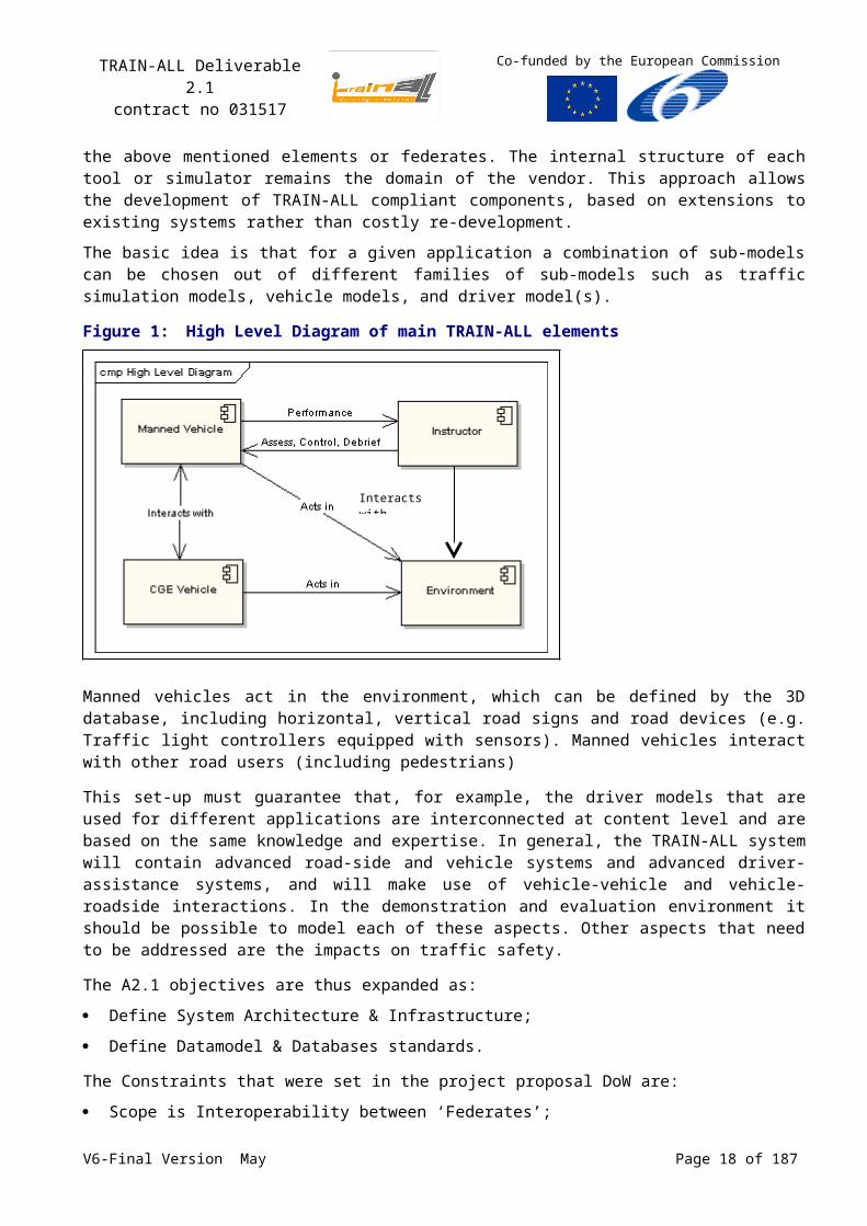
Figure 1:High Level Diagram of main TRAIN-ALL elements
Manned vehicles act in the environment, which can be defined by the 3D database, including horizontal, vertical road signs and road devices (e.g. Traffic light controllers equipped with sensors). Manned vehicles interact with other road users (including pedestrians)
This set-up must guarantee that, for example, the driver models that are used for different applications are interconnected at content level and are based on the same knowledge and expertise. In general, the TRAIN-ALL system will contain advanced road-side and vehicle systems and advanced driver-assistance systems, and will make use of vehicle-vehicle and vehicle-roadside interactions. In the demonstration and evaluation environment it should be possible to model each of these aspects. Other aspects that need to be addressed are the impacts on traffic safety.
The A2.1 objectives are thus expanded as:
Define System Architecture & Infrastructure;
Define Datamodel & Databases standards.
The Constraints that were set in the project proposal DoW are:
Scope is Interoperability between ‘Federates’;
Open standard that tailors High Level Architecture (HLA; see Annex A) principles for DS domain.
The A2.1 Results (Deliverable 2.1) must cover the following aspects:
System Architecture & Infrastructure proposal;
Interoperability Datamodel (FOM) and Agreements proposal;
Databases standard proposal.
Several partners of TRAIN-ALL participated through discussions and information regarding the interoperability needs of their tools and modules.
The proposed solution for the TRAIN-ALL architecture has to be seen as a generic baseline architecture that allows a range of applications to apply to this proposed solution. Consequently, A2.1 will use the planned TRAIN-ALL Demonstrators as guideline for extracting common needs and capture these in the proposed architecture. Specific experiments will need to detail or fine-tune the implementation according to their needs.
V6-Final Version May Page 13 of 140
Interacts with
TRAIN-ALL Deliverable 2.1contract no 031517
Co-funded by the European Commission
2 Architecture Review
TRAIN-ALL faces a typical Information Exchange problem. Tool or model developers should be shielded from the details of the TRAIN-ALL interoperability architecture as much as possible and be able to focus their attention on the modelling aspects rather than on the implementation of the communication middleware of the system.
Architecture is defined as “The structure of components in a program/system, their interrelationships and the principles and guidelines governing their design and evolution over time”.
2.1Architecture Requirements
The tool couplings and tool developments realised in TRAIN-ALL must be generic, modular and flexible; so that one can easily select the tools and modify the type and amount of data transfer depending on the question at hand.
The TRAIN-ALL architecture should allow maximum re-use of existing models and tools (e.g. visuals) to enable short development times for new studies or experiments.
The TRAIN-ALL architecture should be based on existing, open international standards as much as possible.
2.2Architecture Concept and Development Approach
The stated requirements for the ‘Information Exchange’ problem is met best by an architecture based on the concept of interoperable but independent ‘components’. The goal of TRAIN-ALL is to define that open architecture and also define the process and the rules that are required to develop mobility related applications for that architecture.
TRAIN-ALL needs a well-defined flexible architecture that provides interoperability between applications. The most comprehensive concept for distributed simulation architectures is known as 'High Level Architecture' (HLA). HLA is a standard de facto in military simulations where it allows several simulators to interact in order to simulate complex operations. The IEEE 1516 HLA standard [HLA] defines both the services provided by the interoperability layer as well as the structured development process, the FEDEP [FEDEP] that should be followed. The various functionalities of HLA are relevant also for civil simulations to provide interoperability between simulators or simulator components. This makes HLA and the FEDEP very suitable for TRAIN-ALL.
V6-Final Version May Page 14 of 140
TRAIN-ALL Deliverable 2.1contract no 031517
Co-funded by the European Commission
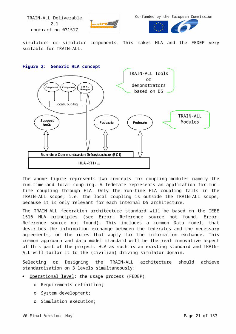
Figure 2:Generic HLA concept
HLA-RTI / ...
Run-time Communication Infrastructure (RCI)
Supporttools Federate Federate
Local Coupling
Comm. Manager
ComponentComponent
The above figure represents two concepts for coupling modules namely the run-time and local coupling. A federate represents an application for run-time coupling through HLA. Only the run-time HLA coupling falls in the TRAIN-ALL scope; i.e. the local coupling is outside the TRAIN-ALL scope, because it is only relevant for each internal DS architecture.
The TRAIN-ALL federation architecture standard will be based on the IEEE 1516 HLA principles (see Error: Reference source not found, Error: Reference source not found). This includes a common Data model, that describes the information exchange between the federates and the necessary agreements, on the rules that apply for the information exchange. This common approach and data model standard will be the real innovative aspect of this part of the project. HLA as such is an existing standard and TRAIN-ALL will tailor it to the (civilian) driving simulator domain.
Selecting or Designing the TRAIN-ALL architecture should achieve standardisation on 3 levels simultaneously:
Operational level : the usage process (FEDEP)
o Requirements definition;
o System development;
o Simulation execution;
System level : the system architecture (HLA)
o Separation between applications and infrastructure;
o Decomposition into functional components;
o Definition of interactions between components;
Technical level : infrastructure (HLA, RTI)
o Services: Data exchange mechanisms;
o Content: Data interchange standards;
o Format: communication/network protocols.
V6-Final Version May Page 15 of 140
TRAIN-ALL Tools or demonstrators based on DS
TRAIN-ALL Modules

TRAIN-ALL Deliverable 2.1contract no 031517
Co-funded by the European Commission
This approach is followed for TRAIN-ALL. In fact, significant part of it is provided by HLA. The technical level for example, is fully defined by the HLA RunTime Infrastructure (RTI). In the same way, a significant part of the usage process is defined by the Federation Development and Execution Process (FEDEP) of HLA Error: Reference source not found.
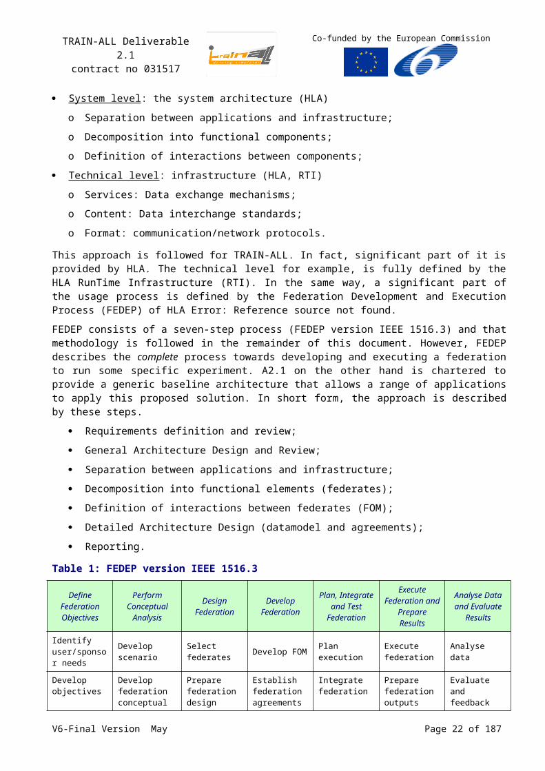
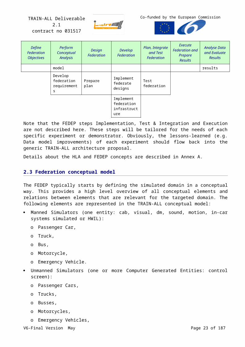
FEDEP consists of a seven-step process (FEDEP version IEEE 1516.3) and that methodology is followed in the remainder of this document. However, FEDEP describes the complete process towards developing and executing a federation to run some specific experiment. A2.1 on the other hand is chartered to provide a generic baseline architecture that allows a range of applications to apply this proposed solution. In short form, the approach is described by these steps.
Requirements definition and review;
General Architecture Design and Review;
Separation between applications and infrastructure;
Decomposition into functional elements (federates);
Definition of interactions between federates (FOM);
Detailed Architecture Design (datamodel and agreements);
Reporting.
Table 1: FEDEP version IEEE 1516.3
Define Federation Objectives
Perform Conceptual
Analysis
Design Federation
Develop Federation
Plan, Integrate and Test
Federation
Execute Federation and
Prepare Results
Analyse Data and Evaluate
Results
Identify user/sponsor needs
Develop scenario
Select federates Develop FOM Plan execution Execute
federation Analyse data
Develop objectives
Develop federation conceptual model
Prepare federation design
Establish federation agreements
Integrate federation
Prepare federation outputs
Evaluate and feedback results
Develop federation requirements
Prepare planImplement federate designs
Test federation
Implement federation infrastructure
Note that the FEDEP steps Implementation, Test & Integration and Execution are not described here. These steps will be tailored for the needs of each specific experiment or demonstrator. Obviously, the lessons-learned (e.g. Data model improvements) of each experiment should flow back into the generic TRAIN-ALL architecture proposal.
Details about the HLA and FEDEP concepts are described in Annex A.
V6-Final Version May Page 16 of 140
TRAIN-ALL Deliverable 2.1contract no 031517
Co-funded by the European Commission
2.3Federation conceptual model
The FEDEP typically starts by defining the simulated domain in a conceptual way. This provides a high level overview of all conceptual elements and relations between elements that are relevant for the targeted domain. The following elements are represented in the TRAIN-ALL conceptual model:
Manned Simulators (one entity: cab, visual, dm, sound, motion, in-car systems simulated or HWIL):
o Passenger Car,
o Truck,
o Bus,
o Motorcycle,
o Emergency Vehicle.
Unmanned Simulators (one or more Computer Generated Entities: control screen):
o Passenger Cars,
o Trucks,
o Busses,
o Motorcycles,
o Emergency Vehicles,
o Pedestrians.
Environment (terrain, lanes, traffic signs):
o Traffic Controller Systems,
o Traffic Information systems,
o Weather conditions.
Tools:
o Instructor Station (select/start/stop/pause scenario, voice/text interaction with student, manual assessment),
o Virtual Instructor (automatic assessment),
o Scenario Control (Automatic Real Time control over scenario and/or Manual RT control),
o Logging/Playback (pure data logging),
o Viewers/Observer stations (stealth).
The project constraints demand not to dig too deep into the internals of a federate (e.g. driving sim.). That means that some modules will not be considered as ‘HLA federates” (e.g. Simulator Sickness Aversion) and have some other means of coupling. At the same time the above list implies that some tools should be seen as stand-alone federates rather than as integral parts of the driving simulator (e.g. Instructor Station or virtual traffic). That separation will be the basis for the Datamodel development. However, in actual TRAIN-ALL demonstrators some tools may be less visible as a separate federate (e.g. the instructor station is an integral part of the THALES Truck simulator).
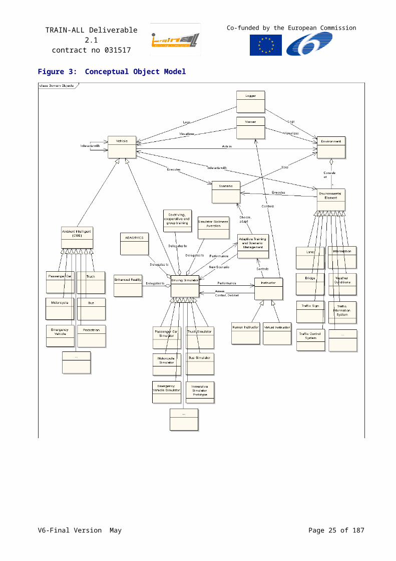
The relations and similarities between the TRAIN-ALL demonstrators and modules and the elements listed above can be depicted in a conceptual object model as shown in Figure 3. This conceptual
V6-Final Version May Page 17 of 140
TRAIN-ALL Deliverable 2.1contract no 031517
Co-funded by the European Commission
object model gives a global overview of the different elements that will be part of the TRAIN-ALL simulation environment.
Figure 3:Conceptual Object Model
V6-Final Version May Page 18 of 140
TRAIN-ALL Deliverable 2.1contract no 031517
Co-funded by the European Commission
2.4Demonstrator and Module descriptions
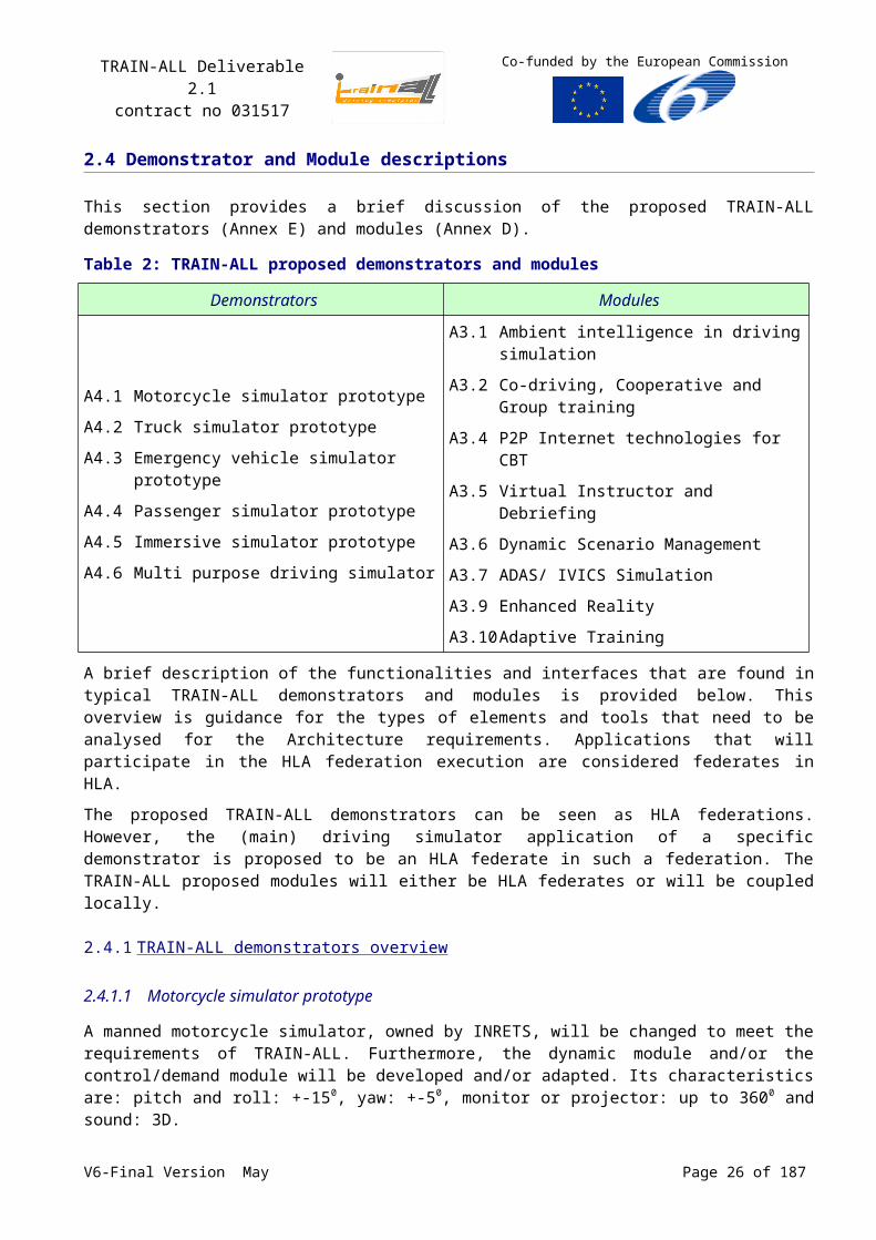
This section provides a brief discussion of the proposed TRAIN-ALL demonstrators (Annex E) and modules (Annex D).
Table 2: TRAIN-ALL proposed demonstrators and modules
Demonstrators Modules
A4.1 Motorcycle simulator prototype
A4.2 Truck simulator prototype
A4.3 Emergency vehicle simulator prototype
A4.4 Passenger simulator prototype
A4.5 Immersive simulator prototype
A4.6 Multi purpose driving simulator
A3.1 Ambient intelligence in driving simulation
A3.2 Co-driving, Cooperative and Group training
A3.4 P2P Internet technologies for CBT
A3.5 Virtual Instructor and Debriefing
A3.6 Dynamic Scenario Management
A3.7 ADAS/ IVICS Simulation
A3.9 Enhanced Reality
A3.10 Adaptive Training
A brief description of the functionalities and interfaces that are found in typical TRAIN-ALL demonstrators and modules is provided below. This overview is guidance for the types of elements and tools that need to be analysed for the Architecture requirements. Applications that will participate in the HLA federation execution are considered federates in HLA.
The proposed TRAIN-ALL demonstrators can be seen as HLA federations. However, the (main) driving simulator application of a specific demonstrator is proposed to be an HLA federate in such a federation. The TRAIN-ALL proposed modules will either be HLA federates or will be coupled locally.
2.4.1 TRAIN-ALL demonstrators overview
2.4.1.1 Motorcycle simulator prototype
A manned motorcycle simulator, owned by INRETS, will be changed to meet the requirements of TRAIN-ALL. Furthermore, the dynamic module and/or the control/demand module will be developed and/or adapted. Its characteristics are: pitch and roll: +-150, yaw: +-50, monitor or projector: up to 3600
and sound: 3D.
2.4.1.2 Truck simulator prototype
A manned truck simulator, situated at AFT-IFTIM, will be changed to meet the requirements of TRAIN-ALL. The simulator evolutions and interfaces requirements & design, which are required to demonstrate the TRAIN-ALL concept, have to be developed.
2.4.1.3 Emergency vehicle simulator prototype
Two manned driving simulators to train emergency driving, provided by WIVW, will be changed to meet the requirements of TRAIN-ALL. The first simulator in its actual version (SV=small version) consists of a projection cabin (diameter 3m) with 300 degree of view, a mockup with generic instruments realised with touch screens, with all operating controls and a sound model with shakers. Additionally, it is equipped with an instruction screen, which can be used to inform the driver about actual errors together with recommendations for better driving. If necessary, the apparatus can be extended to a projection cabin with 8m diameter and integration of a real car. Additionally, a V6-Final Version May Page 19 of 140
TRAIN-ALL Deliverable 2.1contract no 031517
Co-funded by the European Commission
movement system can be integrated. The second simulator (FV= full version) is a high end simulator, with Fokker movement system (6 DoG), a cabin with a BMW 520 and 180 degree projection. Both simulators are operated with the same SILAB software developed by the WIVW.
2.4.1.4 Passenger simulator prototype
From the point of view of h/w and s/w architecture, the first passenger simulator is quite comparable to the emergency simulator, but considerably different in the situation task databases, which must be constructed along the needs of the applications.
The second passenger simulator is the FOERST’s simulator. This is the Smart Simulator owned by CERTH/HIT and the Fahrsimulator F10PF owned by VTI (see Deliverable 1.1).
2.4.1.5 Immersive simulator prototype
Current driving simulation environments use physical mock-ups for the driver's workplace. The combination of Virtual Reality (VR) systems with driving simulation systems can greatly enhance the capabilities of driving simulation systems, particularly for training applications. Current prototypes of VR driving simulators are based on completely proprietary system platforms and components and do not allow flexible use of different vehicle models (consisting of visible geometry as well as vehicle dynamic) and interactive components of the virtual mock-up, e.g. driver information systems. For efficient use of VR driving simulation for training tasks, an integrated system is needed, which combines driving simulation functionalities with virtual mock-ups.
The technologies developed in this project will be prototypically implemented in CRF’s and USTUTT’s immersive simulation environments. CRF’s environment is made up by a minimal mock-up (seat, primary controls with force feedback), mounted on a 6 Degrees of Freedom motion platform. This platform is placed into a CAVE - like 3D visualization system that guarantees a 270° horizontal and 90° vertical field of view. USTUTT’s immersive environment is made up from a 4- or 6-sided CAVE, yielding large horizontal and vertical fields of view up to full surround, and a configurable minimal physical mock-up with sensor/actuator systems for steering wheel, pedals and seat adjustment.
2.4.1.6 Multi-purpose driving simulator
The successful mock-up of a passenger car simulator will be scaled up for the purpose of a multi-purpose driving simulator. Motion and a better visual system will be added. Other points of improvement are the flexibility and modularity of the steering wheel and clutch. All adjustments to the mock-up must be automated or very easy to be made.
2.4.2 TRAIN-ALL modules overview
2.4.2.1 Ambient Intelligence in driving simulation
This module will monitor the actual driver’s profile in a driver simulator (in particular scenarios) and will build a driver behaviour model, utilising intelligent agents’ algorithms. Driver behaviour models will be based upon a set of objective parameters of specific driver’s behaviour during each reference scenario (i.e. mean TTC, TLC right, TLC left, reaction time, traffic rules violations, etc.). Then each participant profile will be anonymised and used to describe a “natural” surrounding traffic participant (of relevant age, gender, nationality, experience…) in a driving simulator scenario with another user.
2.4.2.2 Co-driving, Cooperative and Group training
In the context of professional driving, often a co-pilot is involved (e.g. fire brigade, police emergency driving, emergency medical services, but also in buses and trucks). A main training goal is the competent interaction between driver and co-pilot, depending on the actual traffic situation. In cases V6-Final Version May Page 20 of 140
TRAIN-ALL Deliverable 2.1contract no 031517
Co-funded by the European Commission
of high workload the co-pilot has to support the driver in his/her driving task, whereas in easier situations the co-pilot has to deal with other task (like radio communication). Additionally, the co-pilot is often involved in the navigation task (searching the optimal route). Therefore, training in these application fields means to train a team. A direct inclusion of the co-pilot into the simulation vehicle is not possible because the visualization perspective is driver oriented. Therefore, other training methods must be implemented.
In this project the issue of group training will be researched on technical and behavioural level. Technically, different technologies will be proven for their suitability to allow multiple trainees and trainer-trainee interactions within the same scenario, operating concurrently different driving simulators.
Dependent on the solution, the co-driver’s mock-up can be regarded as a federate, which has interaction with the driver’s mock-up. Based on this, co-driving can be regarded as connecting two federates, so for our case it will not be considered as a module.
2.4.2.3 P2P Internet technologies for CBT
This tool is dedicated to control remotely a simulator; it includes connection to any IP-known simulator, scenario selection, passing commands to the simulator, choosing alternatives, showing technical errors and information of the simulator, showing a video stream of the trainee and different views on the scenario (3 mirror views, driver view and an overview from above the car).
2.4.2.4 Virtual Instructor and Debriefing
One main advantage of simulation is that all scenarios and the effects of driver behaviour must be represented in variables of time and space (i.e. who was at what time at which location?). Based on this information, it is possible to measure objectively the driver’s behaviour. Referencing these measures to normative values will allow to evaluate driver behaviour in terms of good or bad performance of the driving task. This evaluation is one basic function of a virtual instructor. In the next step it has to be proved which consequences will result from the evaluation. The simplest procedure would be an automatic protocol after the simulated ride, supporting the instructor in his/her evaluation task. More sophisticated methods include an immediate feedback during runtime of the simulation, up to a high-end solution, where the actual assessment of the driver’s performance leads to variations in the sequence of simulation scenarios during runtime.
2.4.2.5 Dynamic Scenario Management
Usually, scenarios are described text-based. Common notations of scenarios are script based. The problem of these languages is that they define static locations in the environment. It is not possible to define locations in an abstract manner, like “on a cross”. Sensors and activators are used to send some actions to the traffic entities. The intelligence is put in the environment, like a rail, to lead the entities through the environment. When new dynamic elements, with their own set of actions, are inserted in the environment, the whole environment should be modified to support the new action set. The Dynamic Scenario Management approach puts the intelligence into the dynamic entities, which makes it possible to put new entities into the environment and even change the environment.
To make the driving lessons more effective, it is desirable that the scenarios can be controlled. A framework will be developed that combines the powerful agent technology with the metaphor of a real-world situation, the movie set, to make software more understandable, extensible and more maintainable. This framework will be used to describe and to play scenarios.
2.4.2.6 ADAS/ IVICS Simulation
The rapid development of ADAS and IVICS encounters problems in the use of those systems. In the future, one important application field of simulation will be the demonstration of the system functions V6-Final Version May Page 21 of 140
TRAIN-ALL Deliverable 2.1contract no 031517
Co-funded by the European Commission
and the training on how to operate them. The higher the prevalence of those systems, the higher the need to include safe operation of these systems in driver education, both for novices and experienced drivers. Therefore, the most prominent of such systems is included into the TRAIN-ALL project. The objective is to make drivers able to obtain maximum benefits (in terms of comfort and safety) from ADAS and IVICS, learning also their limitations. Thus, simulator scenarios will be developed for the following ADAS/IVICS: Collision Avoidance System, Lane Deviation Warning system and the use of the mobile phone while driving. Criteria for safe use of these systems will be derived.
2.4.2.7 Enhanced Reality
A basic difficulty of driving is given by the fact that in dynamic situations the relevant parameters are time-based and cannot be “seen” (in contrary to fixed objects and static features of the traffic scene).Important features of a traffic scenario are measures like braking distance, time-to-lane-crossing, time headway, time-to-collision. Because these measures cannot be perceived directly, they must be learnt by experience and often in dangerous situations. An important feature of simulation is the capability of dynamic scene generation to visualize temporal parameters by means of graphical elements (like spotlights which are moved with the vehicle). Also, relevant objects which should be recognized in an actual situation can be highlighted in order to direct the drivers perception in the right direction.
2.4.2.8 Adaptive Training
Traditional simulation is bound to fixed scenarios and scenario blocks, resulting in a strong limitation of sequencing training scenarios. Therefore, tailoring whole simulation rides to the individual trainee without interruptions (i.e. jumping from one simulation location to another one) is impossible. Taking into account the insights of learning theory, best results will be obtained if the learning stuff is presented in an ascending order of difficulties, with additional training of the scenarios where the trainee failed. Work will be based in this activity upon a new architecture, where each scenario can be linked to each other during runtime. The linkage can be direct or conditional. In the latter case, the decision which scenario will follow can be triggered by any other variable (like performance in the previous scenarios or driver state).
2.5 Proposed HLA federation for TRAIN-ALL
The TRAIN-ALL Federation architecture design is intended to be as generic as possible. The architecture team decided on a recommended mapping of the TRAIN-ALL demonstrators and modules onto HLA federates. This mapping and the rationale for this mapping is provided below.
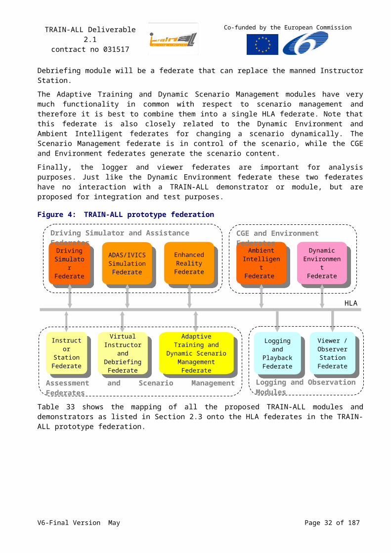
Figure 4 shows the proposed TRAIN-ALL prototype federation. The Driving Simulator federate in this figure represents one of the participating demonstrators, e.g. a passenger car simulator or a truck simulator. Each Driving Simulator can make use of the simulator assistance federates ADAS/ IVICS and Enhanced Reality.
Other modules like the Co-driving, Cooperative and Group training and the Simulator Sickness modules will be integrated or tested within the Driving Simulator directly. The Immersive Simulation module will be part of the immersive simulator prototype (see Annex E), which is a specific instantiation of the Driving Simulator federate.
The Ambient Intelligent module will correspond with one or more HLA federates that will generate unmanned traffic or Computer Generated Entities (CGEs). The Dynamic Environment federate will be responsible for all dynamic environmental elements, like traffic information systems, traffic control systems and weather conditions.
The other four TRAIN-ALL modules not mentioned yet are related to assessment and scenario management. The P2P tool will be a control tool that can be used to remotely control the simulators
V6-Final Version May Page 22 of 140
TRAIN-ALL Deliverable 2.1contract no 031517
Co-funded by the European Commission
and to show video streams of the trainees. This control network is not depicted in the Figure 4, because it is not part of the HLA network. The P2P functionality will also be covered partly by the Instructor Station federate which will be a manned instructor controlling the scenario. The Virtual Instructor and Debriefing module will be a federate that can replace the manned Instructor Station.
The Adaptive Training and Dynamic Scenario Management modules have very much functionality in common with respect to scenario management and therefore it is best to combine them into a single HLA federate. Note that this federate is also closely related to the Dynamic Environment and Ambient Intelligent federates for changing a scenario dynamically. The Scenario Management federate is in control of the scenario, while the CGE and Environment federates generate the scenario content.
Finally, the logger and viewer federates are important for analysis purposes. Just like the Dynamic Environment federate these two federates have no interaction with a TRAIN-ALL demonstrator or module, but are proposed for integration and test purposes.
Figure 4:TRAIN-ALL prototype federation
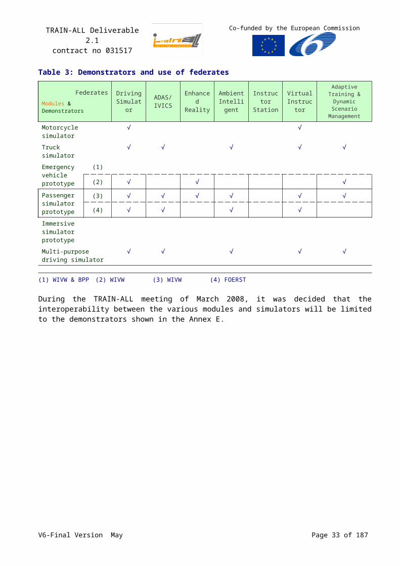
Table 33 shows the mapping of all the proposed TRAIN-ALL modules and demonstrators as listed in Section 2.3 onto the HLA federates in the TRAIN-ALL prototype federation.
Table 3: Demonstrators and use of federatesFederates
Modules & DemonstratorsDriving
SimulatorADAS/ IVICS
Enhanced Reality
Ambient Intelligent
Instructor Station
Virtual Instructor
Adaptive Training & Dynamic Scenario
Management
Motorcycle simulator
√ √
Truck simulator
√ √ √ √ √
Emergency vehicle prototype
(1)
(2) √ √ √
Passenger simulator prototype
(3) √ √ √ √ √ √
(4) √ √ √ √
V6-Final Version May Page 23 of 140
HLA
Viewer /Observer Station
Federate
Logging and PlaybackFederate
Driving SimulatorFederate
Enhanced Reality
Federate
ADAS/IVICS SimulationFederate
Ambient IntelligentFederate
Instructor Station
Federate
Dynamic Environment
Federate
Adaptive Training and Dynamic Scenario
ManagementFederate
Virtual Instructor and
DebriefingFederate
Assessment and Scenario Management Federates Logging and Observation Modules
Driving Simulator and Assistance Federates CGE and Environment Federates
TRAIN-ALL Deliverable 2.1contract no 031517
Co-funded by the European Commission
FederatesModules & Demonstrators
Driving Simulator
ADAS/ IVICS
Enhanced Reality
Ambient Intelligent
Instructor Station
Virtual Instructor
Adaptive Training & Dynamic Scenario
Management
Immersive simulator prototype
Multi-purpose driving simulator
√ √ √ √ √
(1) WIVW & BPP (2) WIVW (3) WIVW (4) FOERST
During the TRAIN-ALL meeting of March 2008, it was decided that the interoperability between the various modules and simulators will be limited to the demonstrators shown in the Annex E.
V6-Final Version May Page 24 of 140
TRAIN-ALL Deliverable 2.1contract no 031517
Co-funded by the European Commission
3 Database Review
The various simulation tools or simulators in the TRAIN-ALL context typically use one or more synthetic databases in which the world is represented. The content and the level of detail vary among tools, depending on the scope of the simulation2. For instance, a traffic simulation tool requires the possibilities to simulate a road network with relatively little emphasis on visualisation. A driving simulator run on the other hand can often be based on a relatively simple road network, but puts large requirements on the visualisation, including a level of detail (road furniture, trees, etc.) that is irrelevant for a traffic flow model.
When modules will be used in the TRAIN-ALL context as integrated in the different demonstrators (see the Table 3), it is obvious that the synthetic databases in the federated entities, i.e. simulator and modules, must be coherent. Due to their different scopes, the various applications or components have different levels of detail, with some common items as well as some unique items. Even when coupling only two simulation tools, database correlation can be a serious problem and the database coherence problem rapidly grows as more tools are brought together in the TRAIN-ALL context.
Figure 5:Visualisation system representation in a Driving Simulator
The choice of a common database (or more accurately a set of local but correlated databases) would solve many problems, because of the common need to describe the associated common road network information data but also in regard to the assessment during the WP5 and WP6 (see Error:Reference source not found). These data will probably be loaded off-line, but some may need to be transmitted through the FOM also. This is relevant when road and environment database are dynamic and change during the course of an exercise.
2 The budget allocated to the visual in a simulator varies usually between 10% to 50% of the total cost of the simulator
V6-Final Version May Page 25 of 140
ProjectorsImageGenerator
Terrain DataBase
Video stream
DisplayHigh-performance
graphics cards
Mixing resizing post-processing
HUDHMDMFD
Computer Generated
Entities
Line of Sight of players
Motion Vehicle model
simulation
Environment interactions
DataBase Generation
System
OpenFlight
TRAIN-ALL Deliverable 2.1contract no 031517
Co-funded by the European Commission
OpenFlight is a format developed, owned and maintain by Multigen Paradigm Inc. It is one of the most widely used and of course constitutes an already common transportable format for the TRAIN-ALL different simulators.
3.1Database Requirements
The road network can be changed for instance for road works or for the purpose of creating new/ repeating training moments.
The logical road network may have to include ’virtual traffic signs’ that are used by CGEs to behave correctly. For example max speed reduced before curves.
One of the key elements of data that should be shared concern databases for terrain (logical road network and visual data).
The ideal set-up would be to start from one master database that covers all elements in all of the tools that are linked. A database-translator should be added to benefit to the other modules/ federates to derive the tool-specific databases from the master DS synthetic database (see Figure 6).
Figure 6:DataBase interaction in a federation
V6-Final Version May Page 26 of 140
Terrain DataBase
1 Driving Simulator federate
Vehicle model simulation
ImageGenerator
ADAS/ IVICS simulation
Other federates
Dynamic Scenario
management moduleVirtual
Instructor
Translation in a common TRAIN-ALL DataBase to be used by the federation for consistency
HLA
Traffic…
…
Translated DataBase
Potential shared SW
Ambient Intelligence
Scenarios
TRAIN-ALL Deliverable 2.1contract no 031517
Co-funded by the European Commission
Several standards of DataBase information access need to be considered. None seem to solve all needs at this time. This document gives some recommendations about:
OpenDRIVE®3, RND (Road Network Description)4 and OSF (Open Scenario Format)5.
3.2Database Concept
In driving simulators people are driving on roads and interacting with other participants in the simulation. The computer generated traffic (CGE) behaves according to certain predefined rules. To apply these, the traffic model must have knowledge of the road, the road surroundings and the other traffic participants. It must know how fast vehicles are allowed to drive, if overtaking is allowed, if the car from the right has priority, if the view to right is obstructed by a house etc. Most of these things are obvious for a normal driver; it is something he deducts from the scene in front of him, recognizing the signs, the type of road he rides on etc., and makes decisions based on all this information. The problem for the computer generated traffic is that computers cannot ‘see’ and interpret the world like a human. Thus, all the relevant elements need to be described in such a way that the computer generated traffic driver can ‘read’ them and generate the appropriate traffic behaviour. Missing information or small flaws in definitions can lead to undesired and/ or unnatural behaviour of the computer generated traffic.
3.2.1 3D-Databases
The 3D-database description file represents the virtual environment presented to the driver and contains also some logical information. The base of this logical information is the road network, which represents the logical connection between roads, the number of lanes on a road, the curvature of a curve in mathematical numbers and many other functions (road signs, road markings). In the typical driving simulator database there is no detailed representation of the surroundings of the roads, a house 3 Km from a road is usually not represented, but a house on the corner a of a junction could be included. From the last, not the low level polygon info would be included, but just a ‘box’ describing the occlusion caused by the house.
The above is of course only true if we make the assumption that students drive on the roads, in military driving simulators where off the road driving is allowed, we need much more information and if we also want to use the used the simulator for tactical training the amount of needed info is even much more.
In database design there are two starting points:- A database which is optimized for the training or research. This database does not have to
represent the real world; this database type is called ‘geo-typical’ in the sense that it represents a typical environment that could exist in the real world. For example an urban environment in western Europe.
- A database which is an exact copy of a part the real world. This database type is called ‘geo-specific’ in the sense that it represents a specific environment that exists in the real world. For example the streets of a capital city.
In the first case, if we want to create our own world, the creative mind is the limit. Obstructions are placed at convenient places, transitions are logical etc. It is even possible to generate the database ‘on the fly’, generic descriptions are enough to generate a road ahead (straight urban road, heavily curved urban road etc).
3 VIRES Simulationstechnologie GmBH4 OKTAL see Error: Reference source not found5 GREEN DINOV6-Final Version May Page 27 of 140
TRAIN-ALL Deliverable 2.1contract no 031517
Co-funded by the European Commission
If the real world needs to be copied, existing Maps, CAD drawings, DEM-data etc. are used to recreate the 3D-world. Most of the time this data can help to create a 3D-representation, but the biggest problem is the logical representation. Most of the required logical information is simply not present in the source data used to create such databases. Furthermore, the conversion tools generally have limitations, and designing a curve-linear road on top of a CAD drawing is tedious handwork, even with the current technology.
Figure 7:Example of a generated synthetic roads network DataBase that needs handwork6
3.2.2 Scenario’s
Driving simulators require deterministic scenarios for training and especially for testing. The scenario should present a blue vehicle from the right at collision course if the scenario so requires. It can be really convenient though to have randomized traffic in the scenario too. Thus, other ‘less relevant’ traffic participants can be present in the scenario without the need to script their behaviour in detail. Simulator manufacturers not only use different traffic models, but also use different ways to specify the scenario for the computer generated traffic. At the moment there is no common description for driving simulator scenarios. Initiatives like the Military Scenario Definition Language7 (MSDL) are aimed at standardization of scenario definitions, but these standards lack specific driving simulator functionality, like dealing with a logical road network description. Where most manufacturers use their own specific scripting language, others use open source languages, such as Lua®8. Some provide hard coded scenarios, which do not allow scenario modifications without changing the core simulator software.
Designing, testing and optimizing traffic scenarios is very time consuming work. Given the lack of standardization, the chances of reuse of scenario code is very small.
Given these disparate scenario languages, standardization of scenarios can only be realized on a meta level. That is: each manufacturer implements a generic description of a traffic situation in their own scenario language, so that different systems will show similar scenarios.
Similar problems exist if you want to connect a driving simulator to other simulators or simulations. The definition of ‘other simulators’ is quite broad, this could mean that you connect two driving simulators, but it could also mean that you connect an intelligent model predicting driver behaviour. 6 TNO credit7 MSDL is an XML data interchange format used to interchange military scenario across systems and
applications8 Lua® is an interpreted oriented object language of script for user’s software programming extension
heavily used in videogamesV6-Final Version May Page 28 of 140
TRAIN-ALL Deliverable 2.1contract no 031517
Co-funded by the European Commission
The solution there is on one hand quite simple, but on the other hand very complex. If only the position (XYZHPR9) is transmitted to the other simulators (or intelligent devices), the receiver has to remap this position on the road network. This remapping leads to errors, for instance with overlapping routes on crossings where the same position can remap to different routes. To overcome this remapping, the simulators could exchange higher level data, like the route they are driving on, but this requires that the database definition files are interpreted in the same way.
3.2.3 What is available?
In the previous paragraphs the importance of a common high level language for describing a database is addressed. For the members of the TRAIN-ALL project it is important that the results of their effort in the project are not restricted by company copyrights and proprietary software. It is also not very likely for the TRAIN-ALL community to define and develop a total new standard, this leads automatically to available languages. At the moment there are the following options:
- OpenDrive,- OKTAL’s Road Network Description (RND),- Green Dino’s Open Scenario Format (OSF).
The OpenDrive project is an open source project which started in 2006, and which aims to define an “open road description file format”. The description of this file format is available on the website [OPENDRIVE].
OKTAL’s RND is currently not open yet, but OKTAL is in the process of making it open and public available, see Error: Reference source not found.
Green Dino’s OSF contains a road description file format which currently covers more than OpenDrive functionality. Green Dino is willing to provide the road description format for TRAIN-ALL, if the TRAIN-ALL consortium plans to develop/adapt a solution for exchanging databases between driving simulators.
3.2.4 Conclusion
At the moment the only open standard for road network description is OpenDrive. This standard is considered not mature enough to provide a logical database definition for the demonstrators in the TRAIN-ALL project. It currently provides methods to describe the roads, intersections, signs, markings etc. OpenDrive is currently more suited for the animation of vehicles than for the simulation of fully autonomous vehicles. It is also limited for describing existing road network The standard is still evolving to encompass other relevant issues. There are currently still relevant issues missing in the standard, for instance a method to describe a blocked view on intersections due to obstructing houses or bushes. This will lead to undesired behaviour in the computer generated traffic, since they will initiate braking responses for traffic that human drivers can not see at such intersections. OpenDrive does provide a solid base for most traffic scenarios, however it is widely supported and has an active community supporting the standard. A disadvantage of OpenDrive is that required support tools to develop the terrain databases are restricted by company copyrights and proprietary software (VIRES).
Therefore, during the TRAIN-ALL meeting in March 2008 it was decided to look into the common development of a “open road description file format”, dedicated to the requirements of TRAIN-ALL demonstrators and driving simulators. For this purpose Green Dino is proposing to deliver its Open Scenario Format (OSF) as a baseline for further development. Within the initial development proposed under TRAIN-ALL, external parties/initiatives (such as OpenDrive and OKTAL/RND) will be contacted for taking part in the discussions and development of this road description file format. A solution could also be to continue and participate in the OpenDrive community for developing this standard.
9 x, y, z, Pitching , Rolling , Yawning V6-Final Version May Page 29 of 140
TRAIN-ALL Deliverable 2.1contract no 031517
Co-funded by the European Commission
3.3Consistency of the DataBase when using it dynamically (WIVW)
The “Adaptive Training” module10 is based on a database architecture called “dynamic database”. The basic idea behind this architecture is to encapsulate training scenarios in small self-contained scenario modules. During simulation, the sequence in which these scenario modules appear can be changed. These changes can be made dependant on the performance of the driver. This allows to
address the trainee’s individual ability level,
vary the scenario difficulty systematically,
avoid mental under-/overload,
achieve faster learning progress.
In dynamic databases, which are used in the WIVW driving simulators, the question of consistency addresses mainly the question of geometric consistency.
Figure 8:Interconnection of scenario environments and driver’s viewpoint
The road network at the exit of this scenario has a bend with rows of houses on each side (red circle). The driver cannot see the scenario environment that is connected next (driver’s perspective below).
In conventional database architectures, the road network can be drawn as a whole as a map true to scale. This property is called "global geometric consistency". Since scenario modules can be designed such that the driver always has a limited area of sight (e.g. in urban scenarios by creating bends with rows of houses on each side of the road, see figure below. On rural roads or highways this can be achieved by using bends, hills, tunnels and crests), a big part of the road network cannot be seen by the driver.
Thus, global geometric consistence is not needed. Dynamic databases make use of the fact that the database has only to be consistent in a small area surrounding the driver. This area has to contain the driver’s area of visibility.
This property is called "local geometric consistency". The algorithm that maintains local geometric consistency during simulation is called "geometric instantiation".
It works as follows: A dynamic database consists of several s.c. scenario modules. Each scenario module represents a scenario and includes the respective road network. When defining the database, the user connects these modules in a topological way. In each simulation step, the geometric 10 See 2.4.2.8, p.22.V6-Final Version May Page 30 of 140
TRAIN-ALL Deliverable 2.1contract no 031517
Co-funded by the European Commission
instantiation algorithm smoothly connects those scenario modules that lie inside the driver’s area of visibility and removes those scenario modules that lie outside this area.
V6-Final Version May Page 31 of 140
TRAIN-ALL Deliverable 2.1contract no 031517
Co-funded by the European Commission
4 Federation Design
Coupling of modules with the different tools will in most cases not be defined at runtime-level, but at the design-time-level. A uniform method to access the modules and tools is necessary. From this uniform method, interfaces can be developed for a particular runtime-level application, modules can be transformed from domain to domain (one domain per demonstrators), and dependencies among modules can be checked. The approach for development of interoperable simulations within TRAIN-ALL is based on the FEDEP process (see Table 1, p.16). However, the TRAIN-ALL Datamodel is in principle implementation independent, i.e. it is not an ‘HLA only’ oriented solution. HLA formalises the information exchange Datamodel in the so-called Federation Object Model (FOM) described in the Object Model Template (OMT) format Error: Reference source not found. The TRAIN-ALL Datamodel will be specified and defined as a FOM.
The information exchange Datamodel of each federate is described by its Simulator Object Model (SOM), which is a subset of the FOM. Newly developed applications should use the HLA RTI interface and subscribe/ publish on data as defined in the TRAIN-ALL FOM. Existing applications could either be ‘re-written’ or supplied with so-called HLA-wrappers to create a TRAIN-ALL compliant tool. The focus within TRAIN-ALL (e.g. the demonstrators) will be on the coupling of existing tools and modules. New development of individual tools will probably not be part of the TRAIN-ALL demonstrators, unless this is absolutely necessary for setting up TRAIN-ALL.
4.1Federate Information Exchange Requests
In order to define a ‘generic’ TRAIN-ALL HLA Datamodel (the TRAIN-ALL FOM) and a set of ‘agreements’ that can deal with the interoperability needs of the different components, the A2.1 team collected information on the data that is typically exchanged between the identified TRAIN-ALL federates and translated that into a generic Datamodel that we intend to apply in the context of TRAIN-ALL. This includes both the data that applications need from external components as well as the data that it will supply to other components. The information on federates was collected using the template given in Annex C, p.97. The template requests information regarding:
General Information (POC etc);
Initial Data (e.g. scenario, terrain data);
Runtime Data Input (e.g. Position data on other vehicles);
Runtime Data Output (e.g. Position data on own vehicle);
Evaluation Data (e.g. student performance assessment data);
Interaction Exchange (e.g. events between module and demonstrator).
The additional requirements of components were also identified and captured as a set of generic ‘agreements’ (See Chapter 5).
Below the Information Exchange issues between the federates are discussed and, if enough information is available, a preliminary federate interface is proposed.
The traffic information has to be available in a “bubble around the driving simulator (visibility distance)”. Any tool (in particular the Driving Simulator) will receive the data it needs by subscribing to the HLA classes of interest.
For the visual system the required update rate for manned/ unmanned simulators shall support smooth movements in the visual. Normally the exchange frequency of data can be (much) lower, but
V6-Final Version May Page 32 of 140
TRAIN-ALL Deliverable 2.1contract no 031517
Co-funded by the European Commission
then the visual (and perhaps other federates also) need to create the in-between data (dead-reckoning, interpolation) to create fluent visualisation. This might mean that additional data is needed to support the dead-reckoning.
For example the Virtual Instructor needs a large amount of data to perform its tasks. We need to make sure that the planned TRAIN-ALL traffic environment tool can support this.
4.1.1 Driving Simulator Interface
4.1.1.1 Definition of exchanged data traffic toward visual, sound and evaluator by INRETS
Each in-traffic moving object is basically marked off by its logical position on the road network (road, curvilinear position, lateral position, relative heading) but several other informations are available
Two additional sets of information are used for positioning it into the road-network description.
Object number
3D position: x, y, z, h, p, r
road position: road, kp, lane, lateral position, relative distance, relative heading, direction
spatial position: symbolic information: same road / lane/ direction, indicators...
The in-traffic moving object (or mobile) categories are:
Vehicles:
o kinematics: speed, acceleration, lateral speed, lateral acceleration, last motion x, y, z
o classes of vehicle: truck, van, bus, car, motorcycle, bicycle...
o performed model: in each vehicle classes (for visualisation)
o traffic indicators status: lights, blinkers, stop, horn...
o axle: wheel axis position & heading (up to 4) & directive wheel relative heading
Pedestrians:
o kinematics: speed, acceleration, lateral speed, lateral acceleration, last motion x, y, z
o classes of pedestrian: individual or group of people, young, old...
o performed model: in each pedestrian classes (for visualisation)
o behaviour: behaviour model in the context of the scenario
The other objects are linked to the roadnetwork main patterns:
Junction:
o junctions & changes in lateral road profile
o geometric description : angle, type, limits
o topologic description : crossed road and kp
o traffic description: junction percentage (used to produce the arriving mobiles)
Road:
o road description: name, type (i.e. motorway/ national...)
o lanes description: width and road-marking
o curvature for bends x, y or sz, pavement description, lateral walls…V6-Final Version May Page 33 of 140
TRAIN-ALL Deliverable 2.1contract no 031517
Co-funded by the European Commission
o sound parameters: reverberation parameters (wav reference)…
Road signs:
o type of sign: descriptive or electronic signs (lane access, speed limit, pedestrian crossing…)
o legibility status
o instruction: speed (ex: traffic signal), information type (recommended, mandatory), distance to comply with…
Traffic lights:
o traffic light status
o legibility status
Some other objects must be described as well: parking (location, free places…).
The weather must be described by different choice with different intensity: fog, rain, night… it will use to compute the distance of visibility.
This information has to be available in a “bubble around the Driving Simulator (visibility distance: i.e. the Line of Sight)”.
4.1.1.2 Driving Simulator Interface (FOERST)
The FOERST simulators can give all types of information at the simulation frame rate (i.e. ~60Hz). A complete and detailed list of the available data would not only be very large, but also burdened with many interrelations between dynamic data and static initial data. The sensible level of detail in the description of output data very much depends on the intended use.
Thus, only some important types of output in reduced detail are listed. Should the need arise for the interchange of data of a specific type; we will give more detailed information later. The abbreviation CP means “Cartesian position” and consists of x, y, z coordinates (precision ~1cm) and Euler angles.
Table 4: Runtime data output by FOERST simulatorType of data Representation Accuracy Comments
Absolute time base Integer 1 ms For synchronization, a relative time base would be sufficient, but absolute time is needed for e.g. display of preloaded animations.
Current world id Integer Graphical database identifier
All vehicle positions and speeds11
CP, CP ~1 cm Having a logical road net as common input, logical coordinates can easily be deduced.
Weather conditions enum, float for fog density
n.a. “night” is a weather condition in this sense.
Instrument values Values for various display instruments as well as state of control elements. Includes e.g. motor RPM (display) and steering wheel angle (input)
11 “Vehicle” should be interpreted as “Moving object of any kind”. The only exceptions are decorative world elements animated based on time only. Also contained are non-physical objects, i.e. enhanced reality objects. This could mean something simple as a moving signal ball or something more complex like a moving double-headed arrow. Enhanced reality objects of the latter type of course also have internal degrees of freedom (c.f. internal states further down).
V6-Final Version May Page 34 of 140
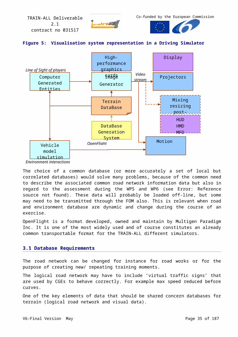
TRAIN-ALL Deliverable 2.1contract no 031517
Co-funded by the European Commission
Type of data Representation Accuracy Comments
Traffic signs12 CP, type and value
The value depends on the sign type.
Traffic light states Set of integers n.a. The mapping of logical traffic light states to displayed traffic lights (signs) is contained in the sign’s value.
Other static objects13 CP e.g. pillars, additional trees, …
Internal states of objects
Integer/ float e.g. “car’s door open” or “pose of a pedestrian”. Largely depends on specific objects in a common graphics database.For cars, standard values are state of all lights and wheel positions.
Note, that only information is listed about the simulated world, no meta-information (i.e. information about the simulation itself). Because of A.I. limitations, certain types of modules might need more information. As an example, consider a virtual instructor component: a human being can deduce another car’s directional intentions not only from blinker signals, but also from e.g. track deviations or wheel movements. For the instructor component, detecting such intentions is not only a difficult and error-prone task, but also unnecessary overhead, because a traffic simulation component could easily transmit such intentions. A proposal in this direction would be:
Table 5: Runtime data output by FOERST simulator (meta-information example)
Type of data Representation Accuracy Comments
Vehicle’s short term route plan
List of Integers List of logical road numbers, the vehicle wants to traverse next
4.1.2 Definition of the Federates
4.1.2.1 Ambient intelligent modules Interface
The ambient intelligent module will correspond with one or more HLA federates that will generate CGEs. These HLA federates will publish vehicle objects that correspond to the vehicle objects to be published by the manned Driving Simulators. For instance, a 3D viewer will subscribe on all HLA vehicle objects and will handle each vehicle object in the same way; regardless whether the vehicle is manned or unmanned.
4.1.2.2 Remote Control Station (Instructor Station Interface)
The P2P tool for networked learning and remote control simulators module will be covered partly by the Instructor Station HLA federate. This federate will be a manned instructor controlling the scenario. For instance, the instructor will be able to start, stop, pause, or reset a scenario run. More functionality will be worked out at a later stadium.
12 Traffic signs may also be contained in the preloaded graphical database.13 Generally, small objects modifying the world on a small scale in order to create specific traffic situations.
For interoperability, there should be an agreement on what kind of objects can be part of a dynamic world modification. There is a trade-off between flexibility, bandwidth requirements and environmental realism. If the set of possible modifications becomes too large, such modification should better be made in terms of interaction exchange.
V6-Final Version May Page 35 of 140
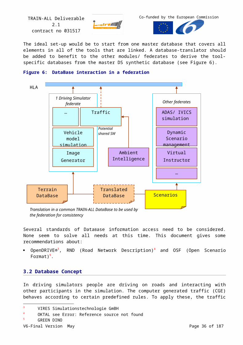
TRAIN-ALL Deliverable 2.1contract no 031517
Co-funded by the European Commission
4.1.2.3 Virtual Instructor and debriefing modules Interface
The Virtual Instructor module will be an HLA federate. It should enable the trainee to start a given driving task and give feedback about the performance during the task. Therefore, it will need the “Error-List” File format describing the misbehaviours of the driver.
Currently, only a reference to the file is communicated and a shared file is used to communicate the errors between both applications. It will be investigated if it is possible to send the error list content itself from the simulator to the Virtual Instructor through HLA. This way, the federates can run on different file systems and all run-time data that is not fixed is exchanged in the same way (by HLA).
Additional the module will need the following events.
From simulator to virtual instructor module:
System_StartIntroductionMovie(ScenarioIndendificationNumber)
System_StartCommentCurrentErrorList(ReferencetoErrorlistFile)
System_StopCurrentMovie();
System_RequestRecommandation(ReferencetoErrorlistFile)
From virtual instructor module to simulator
System_SendRecommandation(ScenarioIndendificationNumber, Performance)
The transfer of real time data is not needed. The failure detection system will monitor the ride. It will be able to measure the following categories of driver misbehaviour. The failures are sorted in realisation to the Gadget Matrix (see Error: Reference source not found).
Table 6: GADGET Matrix levels
GDE Matrix: A: Knowledge and Skills
B: Risk Increasing Factors
C: Self Assessment
Level 1: Vehicle Control;
Level 2: Driving in Traffic;
Level 3: Goals and context of driving; Table 9
Level 4: Goals for life and skills for living.
Table 7: Categories of driver misbehaviour, Level1GDE Matrix Message Measured Value Criteria Comment
Level 1,A RPM too high RPM of the Motor Should not be higher than 4500 U/min
To be adapted to the vehicle
Level 1,A Wrong gear shifting Gear Gears should be incremented
Level 1,A Indicator not set Indicator Should be used on junctions or during lane-changing
Level 1,A Car drifts Lateral Side Forces To be evaluated Physical Law
Level 1,A Track deviation of the idle lane
Track Deviation Not more than +/- one meter
Level 1,A Road boarder exceeded
Track Deviation Distance to road boarder <0
Level 1,A Engine stalled Status of Motor RPM = 0
V6-Final Version May Page 36 of 140
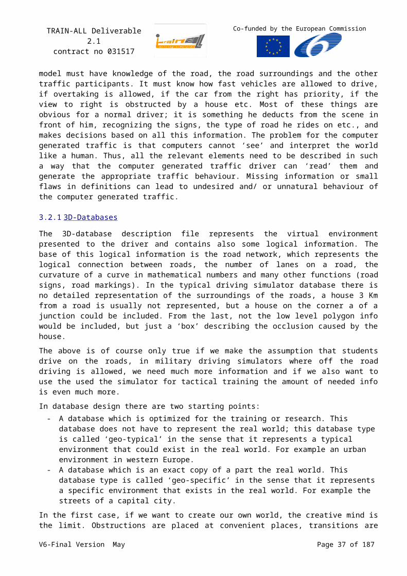
TRAIN-ALL Deliverable 2.1contract no 031517
Co-funded by the European Commission
GDE Matrix Message Measured Value Criteria Comment
Level 1,B Wheels do not grip Road surface, acceleration (+/-)
Level 1,A Handbrake is still active
Speed, Status of Handbrake
Handbrake should be released during driving
Level 1,C Rear mirror not adjusted
Position of rear mirror
Level 1,C Seat not adjusted Position of seat
Table 8: Categories of driver misbehaviour, Level2GDE Matrix Message Measured Value Criteria Comment
Level 2,A Collision Distance to road user =0 Level 2,A Traffic light ignored Traffic Light should not
be redLevel 2,A Light not switched on Sight conditions,
Status of lightShould be switched on at night, rain and fog
Level 2,B Not dimmed Status of lightPosition of road users ahead
Full beam should be switched of if a other road-user is ahead
Level 2,A Speed limits ignored Speed, Speed Limits at Driver Position
Speed < Speed Limit
Level 2,A Right of way disregarded
Traffic rules (Status of traffic lights, traffic signs, Right of way rules, TTC)
To be evaluated
Level 2,A Overtaking prohibition ignored
Track DeviationPosition of other road users
Level 2,B Headway too short Headway HW<Speed (in km/h) / 2 This criteria is the standard thumb-rule in Germany
Level 2,B Driving too slow Speed Speed is continuously 40 km/h lower then recommended speed
Level 2,B Too fast on crossroads
Speed reduction before crossroads
Speed reduction before a junction <10 km/h
Level 2,B Aquaplaning Weather condition, Speed
Car should not be faster than 80 km/h at puddles
Level 2,C Unnecessary hard braking
Deceleration, Traffic Situation
To be evaluated
Level 2,B Full beam not used Weather condition, road users ahead
Driver should use full beam if possible
Level 2,A Stop sign disregarded Traffic signs, speed Driver should make a full stop
Table 9: Categories of driver misbehaviour, Level3GDE Matrix Message Measured Value Criteria Comment
Level 3,B Overtaking on the Wrong Side
Track deviation, Position of other road users.
Driver should follow the traffic rules
Level 3,A U-Turn forbidden Traffic Rules
V6-Final Version May Page 37 of 140
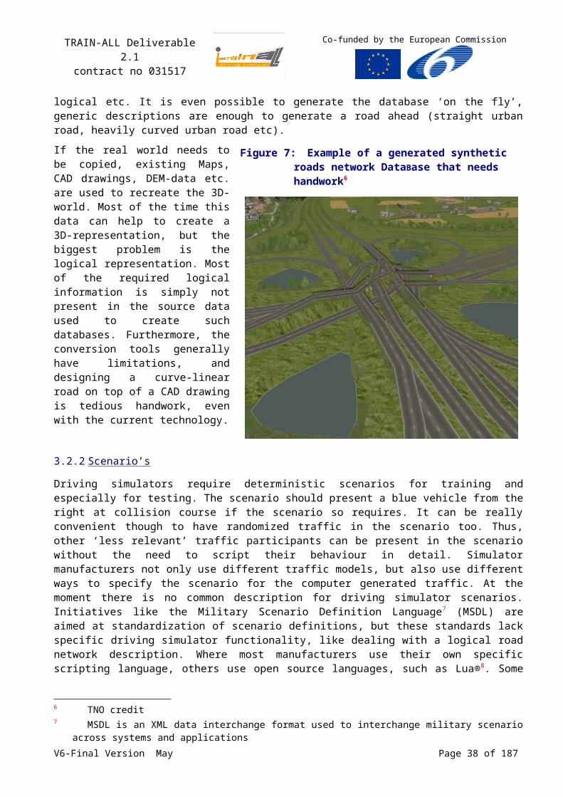
TRAIN-ALL Deliverable 2.1contract no 031517
Co-funded by the European Commission
The Instructor Module will give feedback after each executed scenario/ lesson, whether the trainee should repeat the scenario/ lesson or whether the trainee should continue with the next scenario/ lesson.
Therefore the module will send a performance value to the simulator. The performance values might be:
0 = Scenario completely failed (trainee should repeat).
1 = Scenario completed with some minor mistakes (trainee should repeat this scenario, but not directly);
2 = Scenario completed perfectly (trainee should not repeat this scenario).
4.1.2.4 Adaptive Training and Dynamic Scenario management Interface
The adaptive training module will be part of the Adaptive Training and Dynamic Scenario Management HLA federate. It concentrates on didactic aspects, i.e. to determine a sequence of scenarios that cause the best learning progress. The actual scheduling of the scenarios has to be implemented in the driving simulator.
This process is depicted in the following interaction diagram. We assume that a driving simulator has the following (or similar) components:
scenario control: controls scheduling and execution of scenarios;
performance evaluation: provides information about how the driver has performed in a scenario.
Figure 9:Adaptive Training interface design
adaptive trianing HLA scenario control performance evaluation
RunScenario()scenario state: finished
performance
scenario state: finishedperformance
ChooseNextScenario()
scenario id scenario idscenario state: preparingscenario state: preparing
ScheduleScenario()
RunScenario()
EvaluatePerformance()
EvaluatePerformance()
scenario state: runningscenario state: running
... ... ... ...and so on and so on
and so on and so on
driving simulator
V6-Final Version May Page 38 of 140
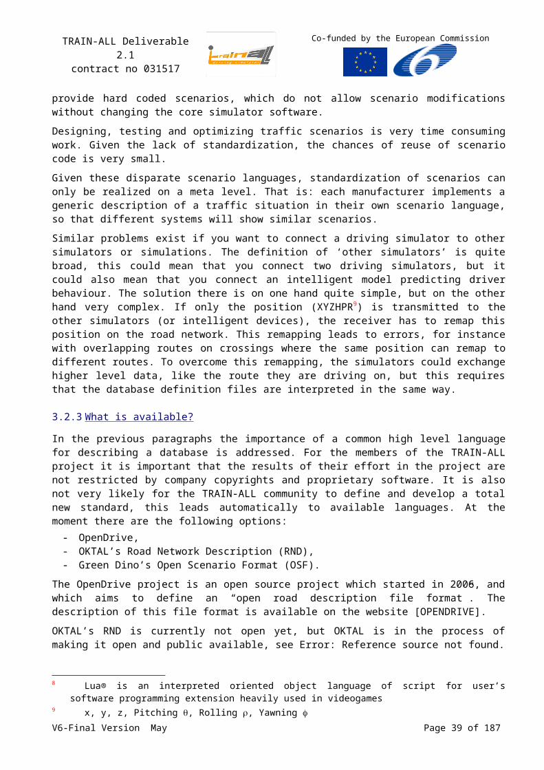
TRAIN-ALL Deliverable 2.1contract no 031517
Co-funded by the European Commission
4.1.2.5 ADAS/IVICS simulation module Interface
The ADAS/IVICS Simulation module will be mapped onto an HLA federate. Data exchange between this federate and a driving simulator is done via HLA, but the interface will be worked out at a later stage.
4.1.2.6 Enhanced reality module Interface
The Enhanced Reality (ER) module will be mapped onto an HLA federate and runs on a separate host computer (see Figure 10). Data exchange between the ER host computer and a driving simulator is done via HLA.
Figure 10: Enhanced Reality interface design
Driving simulator
image generators
traffic simulation
database
Enhanced Reality host computer
HLAHLAER element manager
element specific data
controlcommands
creation/deletion
attributecommands
controlcommands,
elementspecific
data
attributemanipulation
ER element 1
ER element 2
attributecommands
sound system
mockup
vehicle dynamics
1 1
2
3
scenario control
4
5
5
6
6
6
6
7
78
9
910
10
10
The ER module consists of two basic components, the ER element manager and several ER elements (the deployment diagram above shows only two elements). An ER element represents certain ER information that is given to the driver in a certain scenario. This information can be graphical, acoustic or haptic (for more information on ER elements see next section). The ER element manager administers the ER elements that are active within the current scenario.
We assume that the driving simulator has a module called scenario control . This module has information about which ER elements have to be active in the current scenario. To create an ER element for a scenario, the scenario control module sends a s.c. control command to the ER element manager which in turn creates the respective ER elements. If a scenario that contains ER elements is finished, the scenario control module notifies the ER element manager (this is also done by certain control commands ). In this case, the ER element manager deletes the corresponding ER elements.
Within TRAIN-ALL different ER elements are developed in order to help the trainee to understand important aspects of certain traffic scenarios. Depending on didactic aspects, each of these ER elements needs specific information about the traffic environment. Different modules of the driving
V6-Final Version May Page 39 of 140
TRAIN-ALL Deliverable 2.1contract no 031517
Co-funded by the European Commission
simulator provide this information. For example, an ER element that highlights the vehicle in front of the trainee if the TTC is critical, needs the following information:
from the traffic simulation: distance and velocity of the vehicle in front.
from the vehicle dynamics model: the velocity of the trainee.
We call this type of information “element specific data” . It is transmitted to the respective ER element directly via HLA.
Depending on the modality (graphical, haptic, and acoustic) and on element specific data an ER element changes its appearance14. Examples are:
appearing/disappearing, change of colour and animation of graphical elements
panning of acoustic elements
force feedback characteristics of haptic elements
The appearance of an ER element is controlled by attributes of the element. For example, a graphical element has attributes defining its position, colour, shape and animation. Attribute manipulations of currently active ER elements are collected by the ER element manager and translated into s.c. attribute commands . In each simulation step, these attribute commands are transmitted via HLA to the driving simulator. There, the module that is responsible for “displaying” the corresponding element performs the encoded actions. For example, the image generators process commands concerning:
creation and deletion of graphical ER elements,
changes in position,
changes in colour,
etc.
4.2Data Representation
The exchange of information between the modules and simulators has to be identified. This analysis should result in a Datamodel that is as generic as possible and at the same time supports the planned demonstrator cases. This is a problem of technical management and engineering process. An example of the data representation considerations and decisions is given below:
As an example: manned military driving simulators normally use X,Y,Z coordinates since they have complete freedom of movement. A driver may decide to leave the road and continue on the pavement. Unmanned simulators, creating the traffic environment, typically use enhanced curvilinear coordinates (for example by lane lateral distance). This system is adapted to the road shape and allows easier control of entities that stay within the limits of the road-network.
The possible approaches are: define the Datamodel to represent only (X,Y,Z) and provide as part of the federation
agreements a standard algorithm for conversions (X,Y,Z to curvilinear and vv); define the Datamodel to represent only curvilinear and provide as part of the federation
agreements a standard algorithm for conversions (X,Y,Z to curvilinear and vv); define the Datamodel to represent both X,Y,Z and curvilinear and provide as part of the
federation agreements standard algorithms for conversions; define the Datamodel to represent some other position representation and provide as part of
the federation agreements standard algorithms for conversions.
The architecture team decided on the following approach:
14 In this context, we use the term „appearance“ in a very broad sense.V6-Final Version May Page 40 of 140
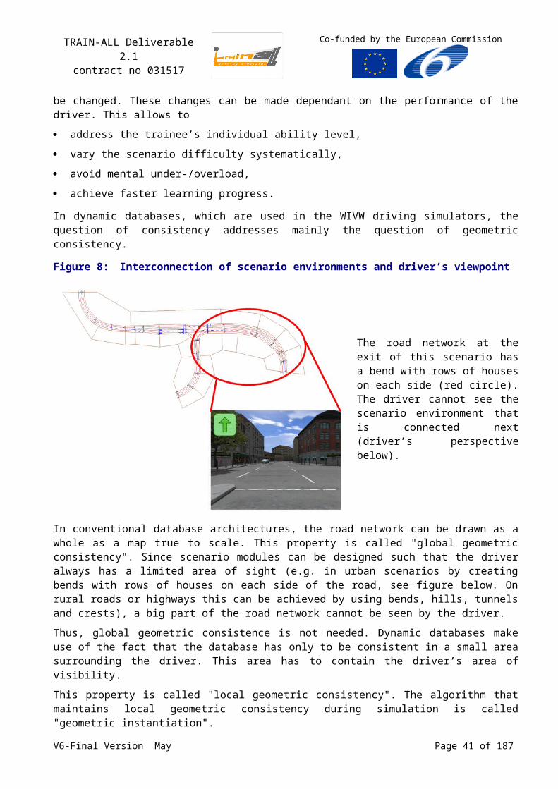
TRAIN-ALL Deliverable 2.1contract no 031517
Co-funded by the European Commission
manned driving simulators need (and use) XYZ;
manned and unmanned simulators (traffic environment) shall always provide XYZ;
unmanned sims (traffic environment) shall always provide curvilinear (in addition to XYZ);
conversion algorithms XYZ-Curvilinear need to be part of the federation agreements.
4.3Data Distribution
The important information for the driver is typically inside a ‘bubble’ around the driver. Traffic for instance must enter and exit this bubble. The simulation outside the bubble is not required to the point of view of the driver. The bubble must be dynamically extended because it depends of the field of view of the driver. Note that the HLA Data Distribution Service may be suitable to support this information bubble concept. Note also that initially the Bubble can be of infinite size to simplify the simulation. That should not be a performance problem as long as scenario’s are kept relatively simple (i.e. limited nr of entities).
4.4HLA FOM Design
The TRAIN-ALL FOM describes the data that can be sent and received within the TRAIN-ALL federation. An important consideration is whether or not to use a standard FOM, e.g. the well-known FOM for real-time applications, the RPR FOM (Real-time Platform Reference Federation Object Model) Error: Reference source not found. The advantage of using a well known standard FOM is that a third party application using the RPR FOM can “see” all vehicles in our TRAIN-ALL federation; it will not be able to see the specific TRAIN-ALL extensions. Examples of existing third party applications include loggers and visualisation tools. The TRAIN-ALL team decided to use the RPR FOM v2 draft 17 as a baseline and add TRAIN-ALL specific extensions as needed.
Below only the highlights of the TRAIN-ALL FOM are listed. All standard RPR-FOM classes are described in Error: Reference source not found and are not listed here. The actual FOM file [TRAIN-ALL-FOM] can be viewed for all details.
‘TrainAllVehicle’ is an object class derived from the RPR-FOM ‘GroundVehicle’ object class. All kind of attributes that are not part of the RPR-FOM vehicle class, but are needed by TRAIN-ALL manned or unmanned vehicles will be part of this class, e.g ‘LaneLateralDistance’ and ‘Lane’ for the curvilinear position of the vehicle, ‘InLane’ to specify whether the vehicle is inside the lane borders, and ‘TTC’ for the Time To Collision.
‘EnvironmentalElement’ is an object class that is a base class of ‘Lane’, ‘Intersection’, ‘Bridge’, ‘TrafficSign’, ‘TrafficInformationSystem’, ‘TrafficControlSystem’, ‘WeatherConditions’, ‘EnvironmentalConditions’ object classes. These HLA object classes provide a way to model a dynamic environment during scenario execution, but it will not be prescribed to model all (static) terrain elements by HLA objects. For example, if all the lanes are static and will be loaded from a database by each federate that needs them, then there is no need to simulate the lanes as dynamic HLA objects.
The ‘FederateState’ and ‘FederationState’ object classes represent the states of the federates and the federation.
The ‘ScenarioManagement’ and “LessonsStep’ interactions are sent by the Scenario Manager federate to instruct federates to load and save scenarios and to start and stop lesson steps.
The ‘DrivingEvaluation’ interactions are sent by the driving simulators and represent the performance of the trainees.
V6-Final Version May Page 41 of 140
TRAIN-ALL Deliverable 2.1contract no 031517
Co-funded by the European Commission
The ‘EnhancedRealityControlCommand’ interactions are sent by the driving simulator to the ER element manager for the creation and deletion of ER elements. The ‘EnhancedRealityAttributeCommand’ interactions are commands from the ER element manager to a driving simulator for the manipulation of ER attributes, i.e. to control the appearance of ER elements in the simulator.
4.5HLA Interface Design
Defining a FOM is not enough to guarantee interoperability between HLA federates. All information additional to the FOM document that is needed for the current and future federates to behave correctly in the federation has to be part of the federation agreements; see Chapter 5.
One aspect of the federation agreements is discussed in this section, i.e. the HLA services that should be used by the TRAIN-ALL federates to behave correctly in the federation. Each federate has to develop an HLA-RTI interface to enter a TRAIN-ALL federation to benefit from the new TRAIN-ALL functionalities. Federates are not required to interface directly to the RTI: HLA middleware can be used to shield off the actual calls to the RTI.
Table 109 provides and briefly discusses the subset of HLA services that should be used by TRAIN-ALL federates.
Table 10: HLA services used by TRAIN-ALL federatesFederation Management
createFederationExecution The first federate that is started will create the federation
joinFederationExecution A federate has to join the federation to communicate with other federates in the federation
resignFederationExecution A federate has to resign from the federation before it stops running
destroyFederationExecution The last federate that resigns will also destroy the federation
Declaration Management
publishObjectClassAttributes To send object updates the object class attributes first have to be published by the federate
publishInteractionClass To send interactions the interaction class first have to be published by the federate
subscribeObjectClassAttributes To receive object updates the federate first has to subscribe on the object class attributes
subscribeInteractionClass To receive interactions the federate first has to subscribe on the interaction class
Object Management
reserveObjectInstanceName Names of objects to be registered have to be reserved
objectInstanceNameReservationSucceeded
Notification that the federate that the object name reservation has succeeded
objectInstanceNameReservationFailed Notification that the federate that the object name reservation has failed
registerObjectInstance Local objects (objects owned by the federate) have to be registered before object updates can be sent
discoverObjectInstance Remote objects (objects owned by other federates) will be discovered by the federate when the owner registers them
updateAttributeValues The federate sends an object update of a local object
reflectAttributeValues The federate receives an object update of a remote object
deleteObjectInstance Local objects are deleted by the federate when they no longer exist
V6-Final Version May Page 42 of 140
TRAIN-ALL Deliverable 2.1contract no 031517
Co-funded by the European Commission
removeObjectInstance Notification that a remote object has been deleted
requestObjectAttributeValueUpdate The federate can request an object update of a (just discovered) remote object
provideAttributeValueUpdate The federate receives a request to provide an object update
sendInteraction The federate sends an interaction
receiveInteraction The federate receives an interaction
Support Services
getObjectClassHandle The federate will use a run-time handle to identify an object class instead of the class name
getAttributeHandle The federate will use a run-time handle to identify an object attribute instead of the attribute name
getInteractionClassHandle The federate will use a run-time handle to identify an interaction class instead of the class name
getParameterHandle The federate will use a run-time handle to identify an interaction parameter instead of the parameter name
4.6TRAIN-ALL Federate Code Example
In this section example code is presented for the Virtual Instructor and Debriefing federate. From the events listed in Section 4.1.2.3 (p.36), the following HLA FOM interactions can be derived.
System_StartIntroductionMovie StartIntroductionMovie
System_StartCommentCurrentErrorList StartEvaluationCurrentErrorList
System_StopCurrentMovie StopCurrentMovie
System_RequestRecommandation RequestPerformanceEvaluation
System_SendRecommandation PerformanceEvaluation
Figure 11: HLA Interactions for Virtual Instructor and Debriefing federate
V6-Final Version May Page 43 of 140
TRAIN-ALL Deliverable 2.1contract no 031517
Co-funded by the European Commission
Since HLA interactions are anonymous by default, i.e. any federate is allowed to receive them and the sender federate is unknown, a traineeId parameter is added to identify the sender or to identify whose performance has been evaluated.
As discussed in Section 4.1.2.3, the error list is currently a shared file, but it would be better if the error list is also part of the FOM. In that case, an interaction DrivingErrorList is added that contains an array of driving errors, and interaction StartEvaluationCurrentErrorList is removed because every time the DrivingErrorList interaction is received the Virtual Instructor knows it has to evaluate these errors. The simulator can decide if the DrivingErrorList interaction is sent only once at the end, every time when an error occurs, or at a regular time interval, etc.
Figure 12: Alternative HLA Interactions for Virtual Instructor and Debriefing federate
The TNO-RCI Middleware (see Section 6.2.1, p.70) can be used to create the federate code. C++ classes are generated for the OMT object and interaction classes. The generated code provides get and set methods for the attributes and parameters and implements all the data encoding and decoding details. The Table 11 shows a small part of the generated code.
Table 11: Sample of code generated by the RCI Code Generatorenum PerformanceValueEnum{ PerformanceValueEnum_TooManyMistakes = 0, PerformanceValueEnum_SomeMinorMistakes = 1, PerformanceValueEnum_NoMistakes = 2};
class RequestPerformanceEvaluationEvent : public HLA1516Event{ public: RequestPerformanceEvaluationEvent(); virtual ~RequestPerformanceEvaluationEvent();
char* getTraineeId(); void setTraineeId(char*);}
V6-Final Version May Page 44 of 140
TRAIN-ALL Deliverable 2.1contract no 031517
Co-funded by the European Commission
class PerformanceEvaluationEvent : public HLA1516Event{ public: PerformanceEvaluationEvent(); virtual ~PerformanceEvaluationEvent();
char* getTraineeId(); char* getScenarioName(); PerformanceValueEnum getPerformanceValue();
void setTraineeId(char*); void setScenarioName(char*); void setPerformanceValue(PerformanceValueEnum);}
The Table 12 shows the actual federate code, i.e. the main function. In this example only a small part is implemented, but it gives an impression on how easy it is to create an HLA connection to a legacy simulation application. In this example the RCI is in control of the main loop (tmControl), but it is also possible that the application keeps control, for instance when the application needs its own control loop. The RCI offers also additional Scheduling Services, e.g. pacing to wallclock time.
Table 12: Sample of the Virtual Instructor federate code#include <stdio.h>#include <signal.h>#include <RCI.h>#include <OMT.h>
RCI_Environment* env;RCI_DefaultScheduler* scheduler;
//**********************************************************************//*** rpeEventCallBack //**********************************************************************void rpeEventCallBack(RCI_Event* anEvent){ // we have received a RequestPerformanceEvaluation event RequestPerformanceEvaluationEvent* rpeevt = (RequestPerformanceEvaluationEvent*) anEvent;
// create an PerformanceEvaluation event PerformanceEvaluationEvent evt;
evt.setTraineeId(rpeevt.getTraineeId()); // lookup the current scenario of this trainee // it is known from the DrivingErrorList interaction(s) evt.setScenarioName(“scenario_4c”); // calculate the trainee’s performance value evt.setPerformanceValue(PerformanceValueEnum_SomeMinorMistakes);
// send the PerformanceEvaluation event env->omScheduleEvent(evt);}//**********************************************************************//**** main_quit //**********************************************************************void main_quit(int h){
V6-Final Version May Page 45 of 140
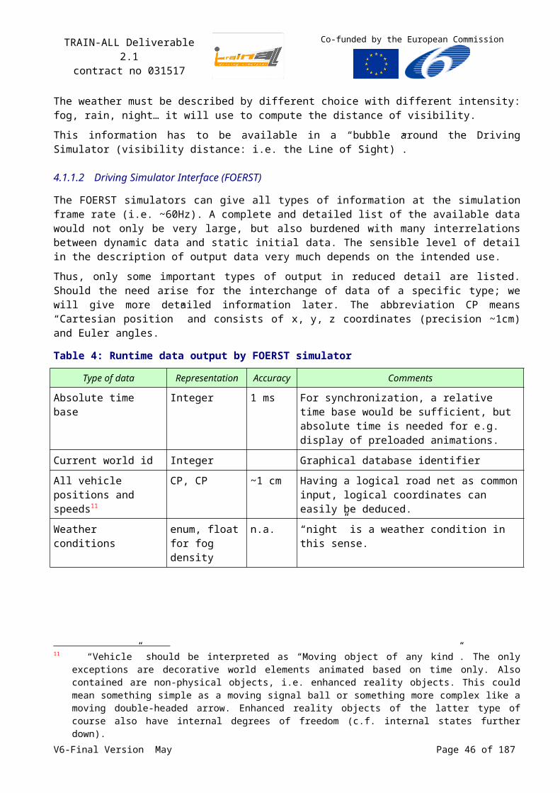
TRAIN-ALL Deliverable 2.1contract no 031517
Co-funded by the European Commission
printf("Quitting main process\n"); env->tmQuit();};//**********************************************************************//*** main//**********************************************************************int main(int argc, char* argv[]){ try { // create the RCI environment env = RCI_Environment::envGetInstance(HLA1516Factory::getInstance(), RCI_Environment::srvGetRCI_Version());
// (create and) join the federation env->fmCreateAndJoinFederation(“TRAIN_ALL.VirtualInstructor”, “TRAIN-ALL-FOM-v1.0.xml”);
// initialise the generated OMT code initOMT(factory->getHLACommunicationServer());
// create a default scheduler scheduler = env->tmCreateDefaultScheduler();
// add RequestPerformanceEvaluationEvent callback FunctionCB *rpeEventCB = new FunctionCB(rpeEventCallBack); env->srvAddCallback("RequestPerformanceEvaluationEvent", rpeEventCB);
// publish and subscribe env->dmPublishEventClass("PerformanceEvaluationEvent"); env->dmSubscribeEventClass("DrivingErrorList"); env->dmSubscribeEventClass("StartIntroductionMovie"); env->dmSubscribeEventClass("StopCurrentMovie"); env->dmSubscribeEventClass("RequestPerformanceEvaluationEvent"); // add main_quit callback signal(SIGINT, main_quit);
// set frequency scheduler->tmSetFrequency(20.0);
// main loop env->tmControl(); // resign (and destroy) env->fmResignAndDestroyFederation(); } catch(RCI_Exception &e) { cout << &e << endl; }
return 0;}
V6-Final Version May Page 46 of 140
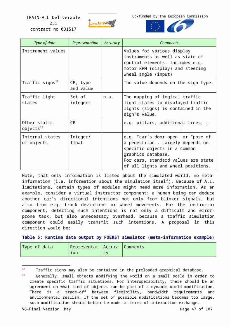
TRAIN-ALL Deliverable 2.1contract no 031517
Co-funded by the European Commission
5 Federation Agreements
The TRAIN-ALL FOM describes the data that can be sent and received within the TRAIN-ALL federation. However, defining a FOM is not enough. All information additional to the FOM document that is needed for the current and future federates to behave correctly in the federation has to be part of the federation agreements. The federation agreements include establishing the procedures for starting and controlling the exercise, managing time advancement and defining common algorithms for specific calculations so as to guarantee a consistent behaviour across federates.
This section will address the federation agreements. Many of these agreements are applicable to all federates, but also agreements between two federates or even an interface agreement currently applicable to only one federate need to be described.
Note that the federation agreements listed here are the agreements to be respected by the federates developers to build a coherent federation. They will be used to define the SOM of the demonstrators (the tools see Error: Reference source not found) and the federated modules (see Table 3).
This section introduces necessary extensions to the FOM, usually called Federation Agreements. These extensions enable multi-industry partners to cooperate and build a federation upon commonly approved bases.
5.1Identification rules
This paragraph presents identification conventions to represent actors among the federation.
5.1.1 HLA RTI and identification
The Run Time Infrastructure (RTI) is the software that provides common interface services during a HLA federation execution.
So the HLA RTI provides an object instance naming mechanism to uniquely identify objects instances. Attribute and parameter references to federate object instances should use the RTI object instance name.
Object names are predetermined by the federates and not automatically generated by the RTI. The entityIdentifier attribute of the RPR-FOM is used to identify entities in addition to their unique HLA object name. Unique application and IDs are predetermined by the federates.
5.1.2 Convention about federation names
The name of the federation is “TRAIN-ALL”.
The FOM will be called “TRAIN-ALL FOM”.
Federation, federate, and object identification.
Federated TRAIN-ALL “platforms”, tools or modules, are fully identified by a threesome: tool Id, module Id, partner Id: ToolIDmoduleIDpartnerID.
5.1.3 DIS identification
The TRAIN-ALL FOM is based on the Real-time Platform Reference FOM v2 draft 17 (see Error:Reference source not found). This FOM is enhanced to be dedicated to the driving.
V6-Final Version May Page 47 of 140
TRAIN-ALL Deliverable 2.1contract no 031517
Co-funded by the European Commission
The RPR-FOM choice insures that at minimum development cost every federate that already respect this interface can enter the TRAIN-ALL federation.
The RPR-FOM has been designed to organize the former PDUs (Protocol Data unit) of DIS into a robust HLA object class and interaction class hierarchy. The priorities for developing this design were, in order:
Support transition of legacy DIS systems to the HLA,
Enhance a-priori interoperability among RPR FOM users,
Support newly developed federates with similar requirements.
Like DIS (see Annex B, 96), the RPR-FOM has been designed to support real time simulations of discrete physical entities such as planes, ships, soldiers, and munitions.
The RPR-FOM uses the Entity Identifier triplet of SiteID-FederateID-EntityNumber (ToolIDmoduleIDpartnerID) to uniquely identify entities in a distributed simulation. Each federate is responsible for establishing a unique SiteID-FederateID (ToolIDmoduleID) pair and generating locally unique entity numbers. There are two purposes for the existence of this identification:
The first is to support legacy applications that are migrating from DIS to HLA, which is the primary motivation for the RPR-FOM design,
The second is the use of wild card addressing in simulation management interactions classes.
This identification must be used only for the objects described in the RPR-FOM. All new objects, which do not inherit from RPR-FOM objects, must use the RTI naming. The use of RPR-FOM objects is described in the GRIM document Error: Reference source not found.
5.1.4 Federation identification
The federation names correspond to the session name and are dispatched through configuration files by the federate in charge of the control and supervision of the federation: i.e. the federation manger.
5.1.5 Federates identification
Federates are identified by their name, used when the federate joins the federation, and their unique DIS identification. Each joined federate must have its owned identification during federation execution.
Table 13: Federates identification (ToolIDmoduleID)
FederatesModules & Demonstrators
Driving Simulator
ADAS/ IVICS
Enhanced Reality
Ambient Intelligent
Instructor Station
Virtual Instructor
Adaptive Training & Dynamic Scenario
Management
11 7 9 1 4 5 6
Motorcycle simulator
1.11.x. 1.7.x 1.5.x
Truck simulator
2.11.x 2.7.x 2.1.x 2.5.x 2.6.x
Emergency vehicle prototype
(1)
(2) 3.11.x 3.9.x 3.6.x
Passenger simulator prototype
(3) 4.11.x 4.7.x 4.9.x 4.1.x 4.5.x 4.6.x
(4) 4.11.x 4.7.x 4.9.x 4.1.x 4.5.x 4.6.x
Multi-purpose driving simulator
6.11.x 6.7.x 6.1.x 6.5.x 6.6.x
V6-Final Version May Page 48 of 140
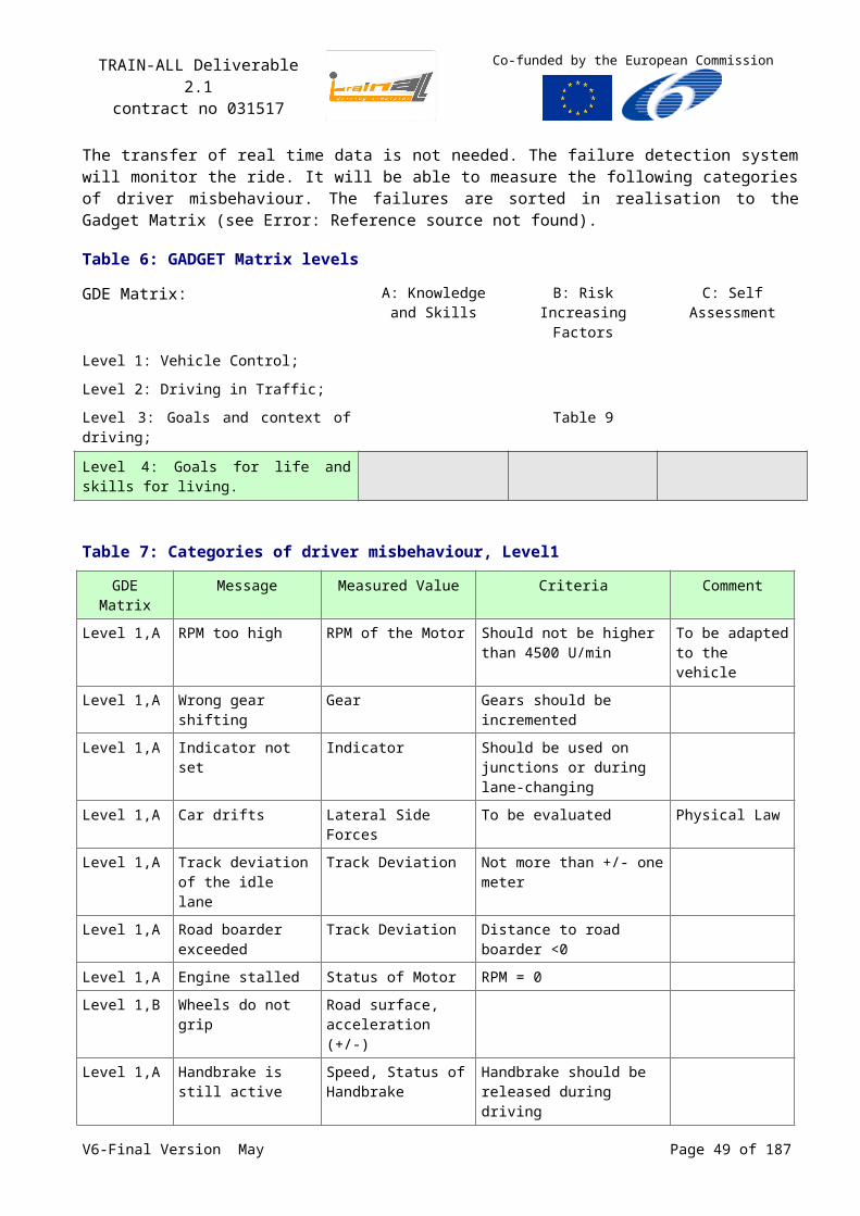
TRAIN-ALL Deliverable 2.1contract no 031517
Co-funded by the European Commission
DIS (see Error: Reference source not found) defines specific values for SiteID, FederateID and Entity Number:
NO_SITE = NO_FEDERATE = NO_ENTITY = 0
ALL_SITES = ALL_FEDERATES = ALL_ENTITIES = 65535
No federate shall be assigned an identification number equal to NO_ FEDERATE or ALL_ FEDERATES.
No entity shall have an entity identifier number of NO_ENTITY or ALL_ENTITIES.
A federate identification number equal to ALL_FEDERATES shall mean that the message addresses all federates.
An entity identification number equal to NO_ENTITY with valid site and federate identification shall address a federate.
An entity identification number equal to ALL_ENTITIES shall mean all entities within the specified site and federate identification.
5.1.6 Objects identification for road driving
The objects are identified wit a septuplet made of:
EntityKind: platform, junction, roadsign (default value for the entity type);
Domain: land (default value vs sea and air domains);
CountryCode: FR, UK… (country of origin of the object);
Category: truck, bus, car, motorcycle, pedestrian… (i.e. for land domain);
Subcategory : subcategory of the object if any;
Specific : model of the object if any;
Extra : other attribute to qualify the object.
The objects for road driving use the defined types in the document Error: Reference source not found: “Enumeration and Bit Encoded Values for Use with Protocols for Distributed Interactive Simulation Applications”. New objects will be identified by new septuplet.
The equipment of the objects (i.e. ADAS/ IVICS) are identified with a unique triplet (ToolIDmoduleIDpartnerID) and an identifier (ID, unsigned long)), which allows to retrieve its characteristics in a federation DataBase. The type of the equipments is also identified accordingly to the document Error: Reference source not found.
V6-Final Version May Page 49 of 140
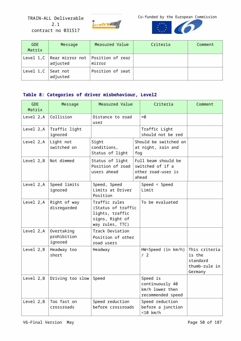
TRAIN-ALL Deliverable 2.1contract no 031517
Co-funded by the European Commission
5.2States
5.2.1 Federation state
The federation state diagram is defined in the following figure:
Figure 13: Federation state diagram
InitializingWaitingRunning
Terminating
{FederationState=Running}{FederationState=Waiting}
{FederationState=Initializing}
{FederationState=Terminating}
Loading {FederationState=Loading}
InitializeExercice
StopFreeze[reason=Recess]
StartResume
StopFreeze[reason=Termination]
StopFreeze[reason=Termination]
RestartPoint[Reason=LoadMilestone]
StopFreeze[reason=Termination]
StopFreeze[reason=Termination]
RestartPoint[Reason=SaveMilestone]
To be precise this diagram represents the state of the federation, not the state of federates; federates will have more states and transitions.
Federation states transitions correspond to HLA objects (interactions and objects), more precisely:
IntializeExercise interaction for exercise initialisation;
StopFreeze interaction according to the RPR-FOM definition Error: Reference source not found;
StartResume interaction according to the RPR-FOM definition Error: Reference source not found;
Automatic transition is used when the job associated to some states is finished. Initialising state will transit to waiting state as soon as initialisation is finished. Loading state will transit to waiting state as soon as Loading restart point is finished.
The states used in the federation are:
Loading: This state corresponds to a load of a restart point. The simulation time is constant for this state.
Waiting: This state corresponds to a wait for a request of Start or Stop. The simulation time is constant for this state.
Running: This state corresponds to a run of the exercise and the simulation time is not constant.V6-Final Version May Page 50 of 140
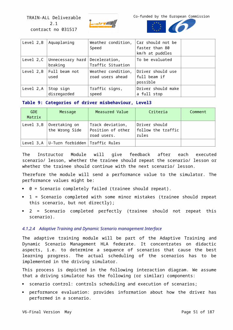
TRAIN-ALL Deliverable 2.1contract no 031517
Co-funded by the European Commission
Terminating: This state corresponds to an exercise termination. All states are in theory connected to this state.
Federation state transitions are managed by the federation manager. Federation state is defined in the FOM by the mean of the object FederationState.
5.2.2 Federate state
The following state diagram describes federates states:
Figure 14: Federate state diagram
ReadyForInitialisation
Initialisation ReadyToExecution
RestartPointLoading
Execution
Termination
ScenarioManagement
StartResume
StopFreeze
ScenarioM anagementRestartPoint
StopFreeze
StopFreezeStopFreeze
StopFreezeStopFreeze
The federate states are compatible with the federation states, federates can define sub states but there transitions are not managed by the federation manager. Scenario management object attributes will include scenario actions enumeration (load, save, new, open, close scenario), federates list destination and initialisation information’s.
Sequence diagrams will describe the federation initialisation steps for a driving exercise and detail the scenarios uploading.
5.2.3 Information provided and/or required by each federate
Each federate publishes and subscribes the attributes and interactions according to its SOM.
Federation Start up and Initialization Coordination:
The use of centralized federation coordination, using federation management tools such as HLA-Control, is recommended.
A Federation Manager is used.
No explicit State Transition Diagram (STD) is used, i.e. no Synchronization Points or specific FOM interactions to implement an STD are used.
V6-Final Version May Page 51 of 140
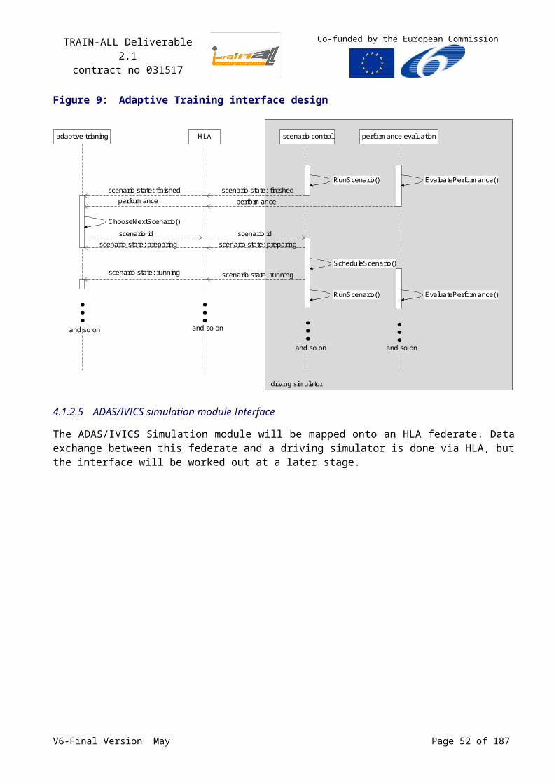
TRAIN-ALL Deliverable 2.1contract no 031517
Co-funded by the European Commission
Initialisation data is not transferred by the FOM. Each Federate has its initialisation data on its local disk before it joins the federation.
5.3Algorithms
5.3.1 Dead Reckoning introduction
In order to always know the correct position of another vehicle, of course it is possible for the federate that “owns” this vehicle to send its position with a relative high frequency to the other federates. For some cases this can result in a lot of data travelling over the network. By using dead reckoning it is possible to reduce the amount of data travelling over the network.
The main identified algorithm is the Dead Reckoning, which is a method for the estimation of the position and orientation of any entity, based on a previously known position and orientation and estimates of time and motion.
The basic architecture of DIS specified the use of a dead reckoning mechanism for reducing communication processing. The RPR-FOM has adopted this mechanism for the same purpose.
For each registered object instance, the use of dead reckoning requires that a federate maintains a dead reckoning model in addition to its own internal model. The dead reckoning model shall follow one of the prescribed dead reckoning algorithms defined by IEEE 1278.1 1995 (see Error: Referencesource not found) and enumerated in the RPR-FOM.
Dead Reckoning shall be applied to all object instances that are derived from the BaseEntity object class.
A federate shall issue a spatial attribute update whenever the differences in position or orientation between its internal model and its dead reckoning model have exceeded established thresholds. The default thresholds for this spatial attribute update condition are also defined by the IEEE 1278.1 1995 standard. The default values for the attribute thresholds are given in the following chapter. The spatial attribute is a variant record. The DeadReckoningAlgorithm provides the discriminant, which specifies the alternative. Each alternative contains only the information required to meet the requirements of the dead reckoning algorithm, such as SpatialStaticStruct for static entities.
5.3.2 Update policy for attribute values and Dead Reckoning
Every federate is able to calculate the dead reckoned current position of a vehicle, based on the previous position and the previous velocity of that vehicle. Whenever the federate that “owns” the vehicle detects that the discrepancy between the dead reckoned position and the real position exceeds some predefined threshold, it will send a position update for that vehicle.
The proposed dead reckoning algorithm for land vehicle is DR_RPW. It calculates the new position, based on the linear and angular velocity and the previous position.
Together with the dead reckoning algorithm, thresholds have to be defined:
whenever the difference between the real position and the dead reckoned position exceeds the translation threshold, an update will be sent to the other federates;
whenever the difference between the real orientation and the dead reckoned orientation exceeds the rotation threshold, an update will be sent to the other federates;
whenever during <time threshold> seconds no updates have been sent, an update will be sent to the other federates.
The three thresholds were agreed upon the following values respectively:
V6-Final Version May Page 52 of 140
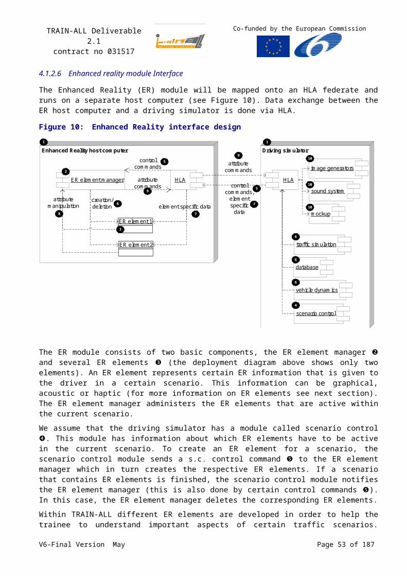
TRAIN-ALL Deliverable 2.1contract no 031517
Co-funded by the European Commission
0.25 meters, 3 degree, 10 seconds.
Late joiners may request attribute value updates and the federates owning those attributes have to provide the attribute values.
As in DIS, it is the receiving federate's responsibility to maintain a dead reckoning model for each external entity of interest. By applying the specified dead reckoning algorithm, the dead reckoning model provides a close approximation of the reflected object instance’s actual spatial attribute’s value. Extrapolation computations are done in relative time with the date of the last supplied kinematics. Even the spatial attribute’s value of the vehicle articulate parts a trailer should be computed.
Reflected spatial attributes shall be used to correct the dead reckoning model so that future approximations are based on the most recent Time, Space and Position Information (TSPI) data.
5.4Coordinates systems
5.4.1 Geographical reference system
The geographical reference system chosen to exchange geographical data is the one used by the RPR-FOM, which is based on DIS protocol. Guidance in the use of RPR-FOM is described in Error:Reference source not found.
Locations are identified using a right-handed geocentric Cartesian coordinate system called the World Coordinate System. The shape of the world is described by the WGS 84 standard. The origin of the coordinate system is the centre of the earth. The axes of this system are labelled X, Y and Z, with the positive X-axis passing thought the Prime Meridian at the Equator, with the positive Y-axis passing through 90 degrees East longitude at the Equator and the positive Z-axis passing through the North Pole. A distance of one unit in world coordinates corresponds to a distance of one meter in the simulated world, and a straight line in the world coordinate system is a straight line in the simulated world.
Figure 15: Geocentric Cartesian Coordinate system
Z axis = Earth axis
North Pole
Prime Meridian
X axis
Y axis Equator
90 Deg East
5.4.2 Entity reference system
To describe the location and the orientation of any particular entity, an entity coordinate system is associated with the entity. This is also a right-handed Cartesian coordinate system with the distance of one unit corresponding to one meter as in the world coordinate system. The origin of the entity coordinate system is the centre of the entity’s bounding volume excluding its articulated and attached parts. The axes are labelled x, y and z with the positive x-axis pointing to the front of the entity, the positive y-axis pointing to the right side of the entity, and the positive z-axis pointing out the bottom of the entity (see Figure 16). The unit is the meter with a double precision format.
An orientation is specified using three angles that describe the successive rotations needed to transform from the world coordinate system to the entity coordinate system. These angles are called Euler Angles and specify a set of three successive rotations about three different orthogonal axes. The order of rotation is as follows:
First, rotate about z by the angle Psi, V6-Final Version May Page 53 of 140
TRAIN-ALL Deliverable 2.1contract no 031517
Co-funded by the European Commission
then about the new y (y’) by angle Theta,
then about the newest x (x’’) by the angle Phi.
The positive direction of rotation about an axis is defined as clockwise when viewed toward the positive direction along the axis of rotation. Angles are expressed in radians.
Figure 16: Entity coordinate system Figure 17: Rotate about z by angle Psi
y
z
x
y x
z
x
x’
z=z’
y
y’
Figure 18: Rotate about y’ by Theta Figure 19: Rotate about x’’ by Phi
x
x’
z=z’
y
y’=y’’
x’’
z’’
x
x’
z=z’
y
y’=y’’
x’’=new x
z’’
new y
new z
5.4.3 Some representations
5.4.3.1 Vector representation
A vector of velocity or acceleration can be described by a triplet (vx, vy, vz) in the same geocentric referential with a float precision.
5.4.3.2 Angle representation
Euler angle (i.e. Psi, Theta, Phi) are represented by a float format in radian or radian/s or radian/s2.V6-Final Version May Page 54 of 140
TRAIN-ALL Deliverable 2.1contract no 031517
Co-funded by the European Commission
5.4.3.3 Point representation
Punctual effects (potholes, clouds) or positions have, like the RPR-FOM, a geocentric representation (location and orientation).
5.4.3.4 Line representation
A line can be expressed by a series of segments, with the same location for the previous end and the beginning of the next. Each segment has its own attributes.
Figure 20: Representation of a line
segment 0
segment 2 segment 1
start point segment 0
end point segment 0
start point segment 1
end point segment 1
start point segment 2
end point segment 2
A line has the following representation:
Attribute Description
NumberOfSegments Number of segments that define the line.
Segments List of segments of the line.
And a segment has the following representation:
Attribute Description
StartPoint Start point of the segment, in a geocentric representation.
EndPoint End point of the segment, in a geocentric representation.
Attributes Attributes of the segment, like height, width…
V6-Final Version May Page 55 of 140
TRAIN-ALL Deliverable 2.1contract no 031517
Co-funded by the European Commission
5.4.3.5 Surface representation
The need is to have a 2D grid, with constant spacing along an axis. The 2D grid could be the following:
Figure 21: Representation of a surface
longitude or x axis
latitude or y axis
South West origin
North East origin
In that representation, the grid has always the same orientation:
an axis along the longitude axis, to the East,
an axis along the latitude axis, to the North,
There is no need to express the size of a cell. This one can be calculated by the client. The needed information can be expressed by the following attributes:
Table 14: Attributes of the gridAttribute Description
SouthWest location Represent the South West origin point of the grid. The location point has a geocentric representation.
NorthEast location Represent the North East origin point of the grid. The location point has a geocentric representation.
NumberOfGridAxes Number of axes that define the grid.
NumberOfCells Number of cells along the axes. The cardinality is NumberOfGridAxes. The first axis is the East axis, the second, the North axis.
5.5Curvilinear coordinate system
This system well adapted for “military” positioning (ship, aircraft, all-terrain vehicle) will be enhanced for driving with the following curvilinear coordinates system better suited for road positioning, as proposed by INRETS.
See the chapter 4.1.1.1, p.33 and the chapters 4.2, p.40 and 4.4, p.41.
V6-Final Version May Page 56 of 140
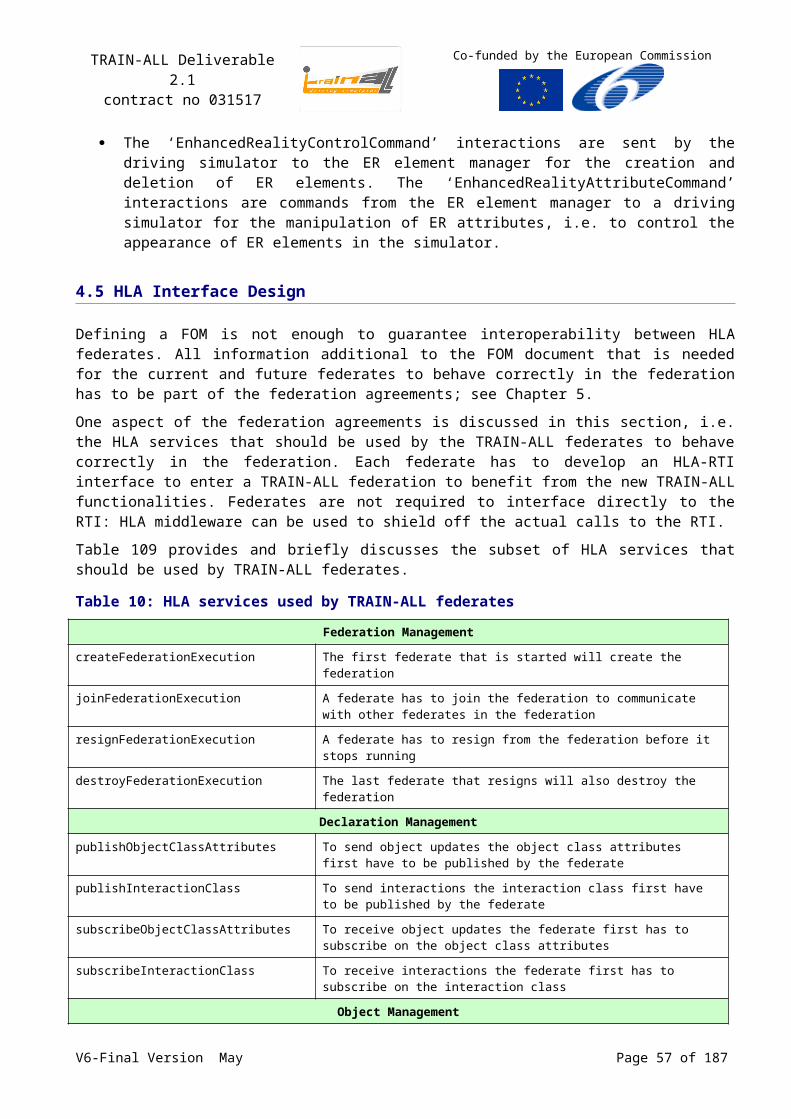
TRAIN-ALL Deliverable 2.1contract no 031517
Co-funded by the European Commission
5.6 Protocols
5.6.1 Standard HLA
The standard used to implement the norm HLA interface version 1.3 implemented by the Simulation Interoperability Standards Organization (SISO).
The chosen RTI is the one free from DMSO (see ); even if it isn’t now distributed by the DMSO, it was the most used because of its free use. When the use of HLA becomes most obvious, the standard 1516 would be selected as soon as future TRAIN-ALL users can afford to buy the RTI 1516 and some HLA development tools.
Table 15: Services that are required in the simulationRTI Ambassador Federate Ambassador Chapter title
Create Federation Execution -
FederationManagement
Join Federation -
Resign Federation Execution -
Destroy Federation Execution -
get Object Class Handle start Registration For Object Class
DeclarationManagement
get Attribute Handle stop Registration For Object Class
publish Object Class -
subscribe Object Class Attribute -
get Interaction Class Handle turn Interactions On
get Parameter Handle turn Interactions Off
publish Interaction Class
register Object Instance discover Object Instance
Object Management
turn Update On For Object Instance
request Class Attribute Update Value provide Attribute Value Update
request Object Attribute Update Value
Update Attribute Values reflect Attribute Values
delete Object Instance remove Object Instance
send Interaction receive Interaction
register Object Instance discover Object Instance
5.6.2 Federation Management
The used services of connection, disconnection are:
Creation and destruction of a federation,
Joining and resigning a federate to a federation,
When a federate wants to join a RTI federation, it first invokes the Create Federation Execution service, in order to create a new federation execution. If the specified federation execution already exists, the corresponding exception is sent and is ignored by the federate. Next, the federate must use the Join Federation Execution service. When a federate wants to quit a federation execution, it must invoke the Resign Federation Execution service. It must next try to destroy the federation
V6-Final Version May Page 57 of 140
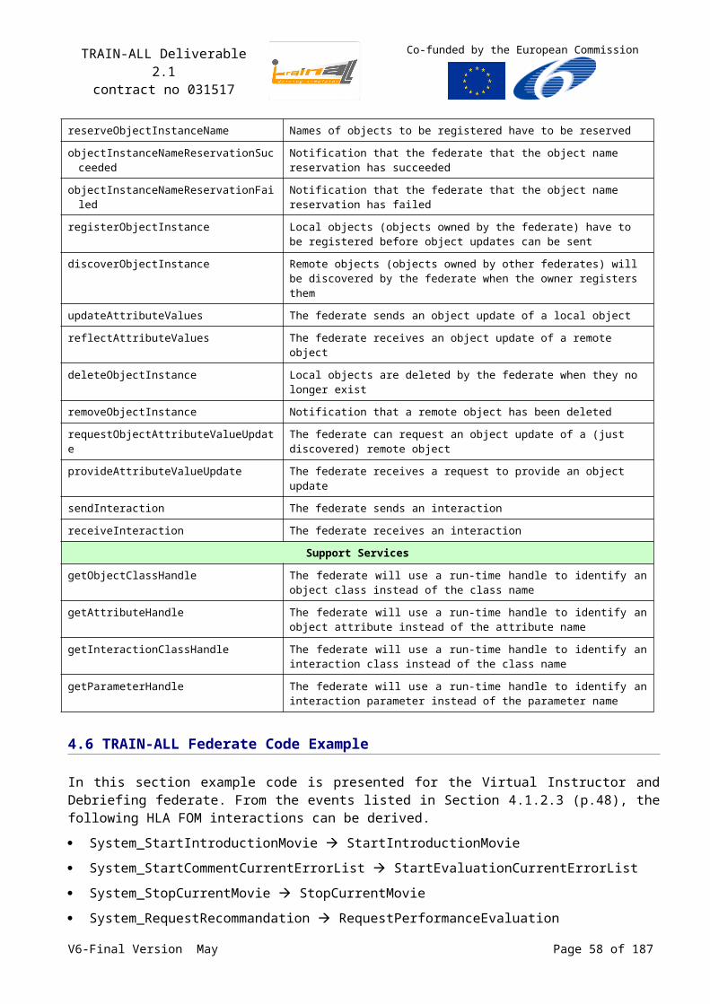
TRAIN-ALL Deliverable 2.1contract no 031517
Co-funded by the European Commission
(Destroy Federation Execution service). An Exception can be sent if federates are still joined to the federation execution.
5.6.3 Declaration Management
TRAIN-ALL federates publish and subscribe objects and interactions classes just after their connection to the federation. It is not possible to publish, subscribe, unpublish or unsubscribe during the simulation (unsubscribe Object Class, unpublish Object Class Attributes, unsubscribe Interaction Class, unpublish Interaction Class). Unpublication and unsubscription can be done only when the federate resigns the federation.
The following diagram depicts the publication and subscription of object class. If “Another Federate” resigns the federation before “A Federate”, the RTI informs “A Federate” with the Stop Registration For Object Class service.
Figure 22: Object class publication and subscription
A Federate : Federate
: RTI Another Federate : Federate
getObjectClassHandle
getAttributeHandle
publishObjectClassAttributes getObjectClassHandle
getAttributeHandle subscribeObjectClassAttributes startRegistrationForObjectClass
The federate gets object class and attribute handles for the publication
The federate gets object class and attribute handles for the subscription The RTI notifies the
federate that registration of new objects is advised
The following diagram depicts the publication and subscription of interaction class. If “Another Federate” resigns the federation before “A Federate”, the RTI informs “A Federate” with the Turn Interactions Off service.
Figure 23: Interaction class publication and subscription
A Federate : Federate
: RTI Another Federate : Federate
getInteractionClassHandle getParameterHandle
publishInteractionClass getInteractionClassHandle
getParameterHandle subscribeInteractionClass
turnInteractionsOn
The federate gets interaction class and parameter handles for the publication
The federate gets interaction class and parameter handles for the subscription
The RTI notifies the federate that the specified class od interactions is relevant
V6-Final Version May Page 58 of 140
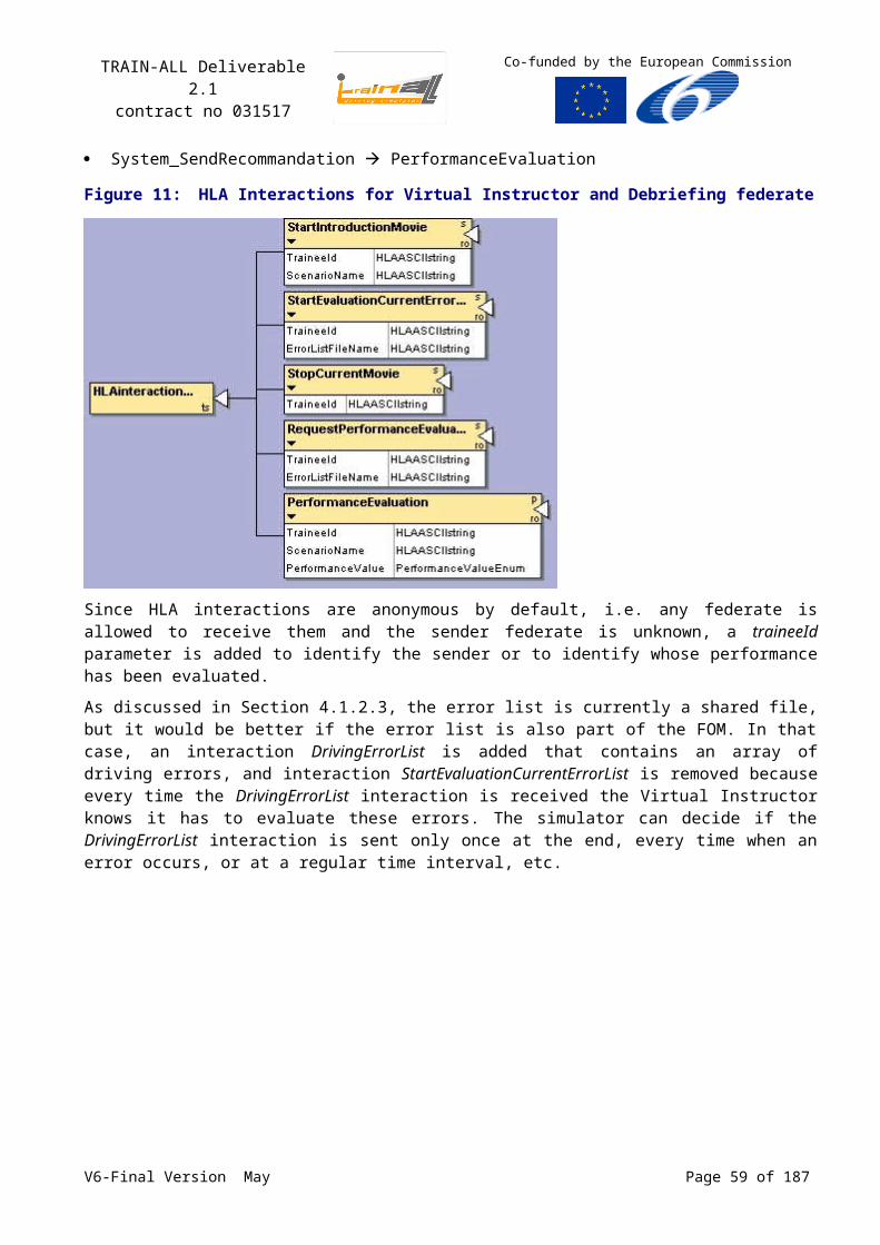
TRAIN-ALL Deliverable 2.1contract no 031517
Co-funded by the European Commission
5.6.4 Object Management
The Object Management supplies two main services:
It controls the life cycle of the instances of objects.
It manages the exchange of data between the federates through the sending of attributes updates and of interactions.
The following diagram describes the life cycle of an object:
Figure 24: Object management
A Federate : Federate
: RTI Another Federate : Federate
registerObjectInstance discoverObjectInstance
turnUpdateOnForObjectInstance
requestClassAttributeUpdateValue provideAttributeValueUpdate
updateAttributeValues reflectAttributeValues
deleteObjectInstance removeObjectInstance
The federate “A Federate” registers an instance of object with the RTI by invoking the Register Object Instance service. The RTI informs the federate “Another Federate” of the existence of the new object through the Discover Object Instance service. The federate “A Federate” is then sought by the RTI to publish the changes of states of the new object (Turn Updates On For Object Instance service).
If the federate “A Federate” destroys the instance of object (Delete Object Instance service), the federate “Another Federate” is informed by the RTI through the Remove Object Instance service.
A federate late arrived or a late subscription can pull an explicit query of update of the information thanks to the Request Class Attribute Value Update and Request Object Attribute Value Update services, respectively.
A federate publishing the information is notified by the RTI thanks to the Provide Attribute Value Update service.
The update of an attribute is introduced by a federate publishing the instance thanks to the Update Attribute Values service. The RTI spreads the information to all federates which signed this object class through the Reflect Attribute Values service. The updates of attributes are realized in case of value change only.
The following diagram depicts the interaction transmission:
The federate “A Federate” sends an interaction by invoking the Send Interaction service.
V6-Final Version May Page 59 of 140
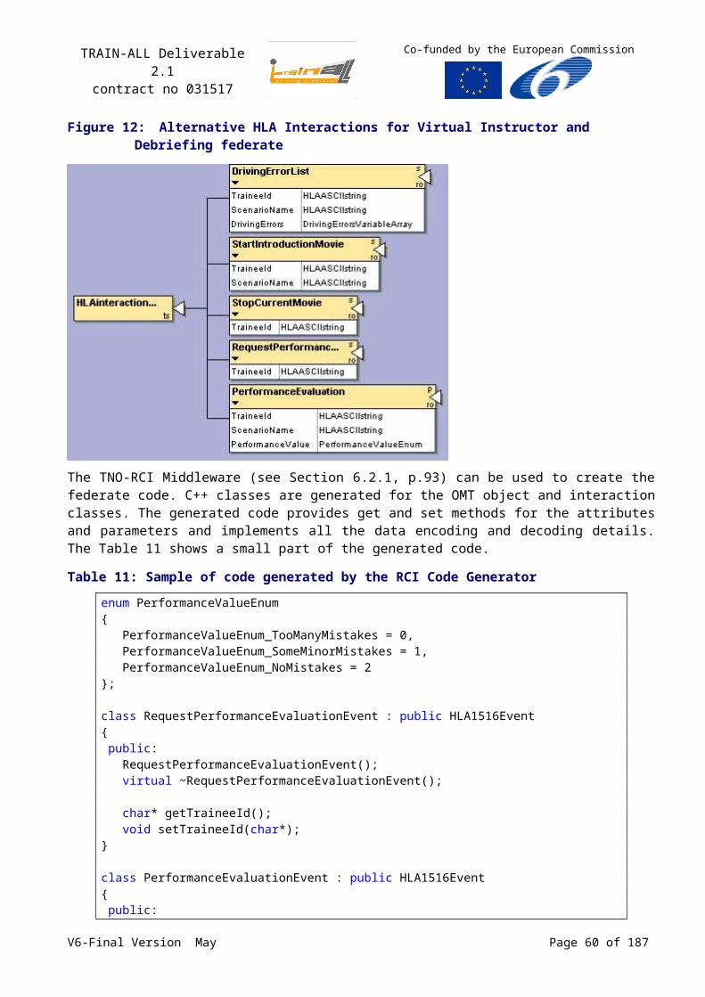
TRAIN-ALL Deliverable 2.1contract no 031517
Co-funded by the European Commission
The RTI informs the federate “Another Federate” that an interaction arrived by invoking the Receive Interaction service.
Figure 25: Interaction transmission
A Federate : Federate
: RTI Another Federate : Federate
sendInteraction receiveInteraction
5.6.5 Ownership Management
No Ownership Management service is required.
Ownership management would be used by joined federates and the RTI to transfer ownership of instance attributes among joined federates. The ability to transfer ownership of instance attributes among joined federates shall be required to support the cooperative modelling of a given object instance across a federation. While many federates are able to become publishers of a single class attribute, only one federate is able to update the value for each instance attribute. This federate is known as the owning federate. An attribute can either be owned by one federate or no federates at any instant in time. Ownership transfer of an attribute involves Divestiture by the current owner and Acquisition by the new owner.
5.6.6 Data Distribution Management
No Data Distribution Management service is required.
5.6.7 Time Synchronization
HLA Time Management is very powerful to run as-fast-as possible simulations, where simulation time has no relation with the wallclock time. The RTI deals only with logical simulation times and it is the federate’s responsibility to relate this time to the wallclock time.
For real-time simulations, the most common way to synchronize all local simulation times between the federates is by synchronizing all system clocks and pacing each federate’s simulation time to the local system clock. A central NTP Timeserver shall be provided and all federates shall slave their local system clock (used for the timestamps) to this server. The windows time service provides this function.
The federates are supposed neither time-regulating nor time-constrained. However, federates must place time stamps on the messages (e.g., updating instance attribute values and sending interactions) according to RPR-FOM rules Error: Reference source not found, Error: Referencesource not found, in all cases (Time management or not) to indicate when these actions occur during the federation execution.
No HLA Time Management is used, i.e. there are no Time Constrained or Time Regulating federates.
NTP is used to synchronise all system clocks.
Timestamps are used, which are part of the IEEE 1516 RTI API.
To synchronize the federates when during a freeze/ unfreeze sequence, the federation manager should ask freeze/ unfreeze orders in simulated time. Each federates should wait for this time to stop
V6-Final Version May Page 60 of 140
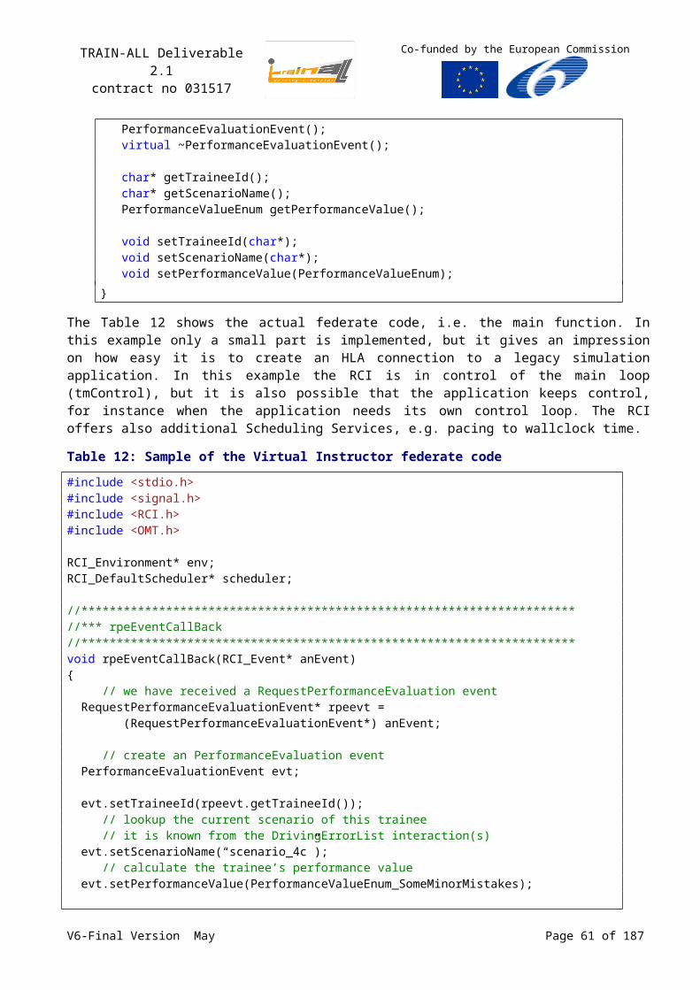
TRAIN-ALL Deliverable 2.1contract no 031517
Co-funded by the European Commission
their running. The federation manager has also the possibility to send a ScaleFactorUpdate to the whole federates before running in order to accelerate or decrease the pacing of the simulation. The rhythm of elapsed time is adapted by each federate. this may be useful for the replay function.
5.6.8 Data marshalling
IEEE 1516 encoding rules and IEEE 1516 padding rules will be used, unless the RPR-FOM defines an alternative encoding.
Endianness will be Big Endian, which is the RPR-FOM default.
5.7Other considerations and versions
5.7.1 What could be the federation execution
The Federation management effects cover the rules used for managing a federation. In this case, the federation state object will be defined from each federate. For example if all federates state is “Execution” then the federation state is “Execution”.
The conceptual model for the driving exercise execution is defined in the following diagram:
Figure 26: HLA management effects conceptual model for exercise execution
Other federates.
EXSU and IEXE federates
[ReadyToExecution]Exercice Start:
The federate starts execution
The federate restores its context[ReadyToExecution]Federation Restore:
[ReadyToInitialization]Federation initialization:
The federate load the database and the scenario
Federate Status:
The federate joint the federation
The federate suspends the execution
The federate stops the execution and resign the federation
The federate saves its contexts[Execution]
Federation Save:
[Execution]Exercice Stop:
[Execution]Exercice Freeze:
[Termination]Federation quit:
The federate resign the federation and quit.
The federation is initialized
The exercice is running
Close session
5.7.2 Others federation considerations
Regarding the data logging, it is supposed that the whole traffic involved in the federation has to be logged: a Data Logger should be supplied with the federation manager. V6-Final Version May Page 61 of 140
TRAIN-ALL Deliverable 2.1contract no 031517
Co-funded by the European Commission
There is no security requirement in the federation running. The data management respect the rules of Ethics mentioned in the Error: Reference source not found document.
The Network configuration has to be tailored according to the set up of PC in the federation.
The available algorithms could be completed by common driving algorithms (see 5.3): Calculus of the Distance, Time to Collision (the algorithm are very different…), Time to Lane Crossing, curvilinear conversion, etc.
5.7.3 Software versions
The software and tools used in or developed for the TRAIN-ALL federation shall support specific operating systems and shall use specific third party software. The applicable agreements are stated in the table below.
Table 16: Software versionsItem Version Comment
HLA specification HLA 1.3
RTI DMSO HLA 1.3 The usage is free, the performance are OK for demonstration federations
OMDT
FOM
FED file
RID
OpenFlight 16.1
Openscenegraph
OpenDrive
…
V6-Final Version May Page 62 of 140
TRAIN-ALL Deliverable 2.1contract no 031517
Co-funded by the European Commission
6 HLA Tools and Middleware
This Chapter discusses the status of available Commercial and Open Source implementations of HLA Interoperability software. The overview of software includes both the standard HLA RTIs as well as middleware that provide abstractions of the RTI.
6.1Survey of RTIs
This paragraph discusses requirements and status of available Commercial and Open Source implementations of HLA Interoperability software.
6.1.1 Existing commercial and open source RTI
Table 17 and give an overview of the status of available Commercial and Open Source implementations of the HLA Run-time Infrastructure (RTI) software. The list is not meant to be complete.
Table 17: Existing RTI commercial licenceName Vendor Standard Bindings
Chronos RTI Magnetar Games IEEE 1516 C++, .NET
MÄK RTI MÄK Technologies 1.3, IEEE 1516 C++, Java
Mitsubishi ERTI Mitsubishi Electric Corp. and Mitsubishi Space Software Co. Ltd 1.3 C++
Openskies RTI Cybernet Systems 1.3, IEEE 1516 C++
Pitch pRTI Pitch Technologies 1.3, IEEE 1516 C++, Java
RTI NG Pro Raytheon Virtual Technology Corporation 1.3, IEEE 1516 C++, Java
TNO RTI TNO Defence, Safety and Security 1.3 (partial), IEEE 1516 (partial) C++, Java
Table 18: Existing RTI open source licenceName Vendor Standard Bindings Licence
BH-RTI Beijing University of Aeronautics and Astronautics Virtual Reality Laboratory
1.3, IEEE 1516 Unknown Unknown
CERTI ONERA 1.3 (partial) C++ GPL
EODiSP HLA P&P Software IEEE 1516 (partial) Java GPL
GERTICO15 Fraunhofer IITB 1.3 Unknown Unknown
Open HLA 1.3 (partial), IEEE 1516 (partial)
Java Apache License
RTI NG DMSO 1.3 C++, Java Not open source, but free use of
15 German RTI base on CORBAV6-Final Version May Page 63 of 140
TRAIN-ALL Deliverable 2.1contract no 031517
Co-funded by the European Commission
Name Vendor Standard Bindings Licence
binaries.
RTI-S US JFCOM J9 Directorate 1.3 (partial) C++, Java US Government
The Portico Project
littlebluefrog labs 1.3 (partial), IEEE 1516 (partial)
Java, C++ CDDL
6.1.2 Implementation of the HLA Run T ime Infrastructure
In this paragraph we investigate different implementations of the HLA Runtime Infrastructure. The following table, which is taken from the DMSO website Error: Reference source not found, gives an overview about existing commercial RTIs.
Table 19: RTI market production (Error: Reference source not found)Name Company Version Spec. API Platform
GERTICO Fraunhofer IITB 0.33 1.3 C++ Windows XP
RTI-NGmatrex MATREX 5.0 1.3 C++ Redhat Linux 4 32bit/64bit
MAK High Performance RTI
MAK Technologies
2.0 1.3 C++IRIX 6.5.14 f Red Hat Linux 7.2Win32 (Windows NT/2000/XP)
3.0 1516.1 C++ DLC Win32
pRTI 1.3
Pitch AB
2.2
1.3
C++
Win32
2.1 Redhat 8.0
1.2 Windows NT 4.0
1.0 r51.0 r3 Java
Java 2
2.0Win32
C++ Win32 (Windows NT/2000/XP)
pRTI 15162.1
IEEE 1516.1
C++
Win32Java
3.0.1
RTI NG PRO
Virtual Technology Corp (VTC)
v2.0
1.3 C++
Sun Solaris 8
v3.0 Red Hat Enterprise Linux
VTC & SAIC 1.0 Solaris 2.8
RTI Next Generation SAIC
1.3v2 1.3v3.1 1.3v3.2 1.3v4 1.3v5 1.3v6 1.3v7 1.3v8 1.3v9 v6.7
1.3 C++ Solaris 2.6
Matrex RTI NGDynamic Animation Systems
v4.1 1.3 C++ RedHat Linux 9
ERTIMitsubishi Space Software Co., Ltd. (MSS) 1 1.3 C++ Solaris 2.7
1.8 1.3 C++ Linux Kernel 2.4.7
V6-Final Version May Page 64 of 140
TRAIN-ALL Deliverable 2.1contract no 031517
Co-funded by the European Commission
Name Company Version Spec. API Platform
Mitsubishi Electric Corporation (Melco), and Mitsubishi Space Software Co. Ltd (MSS)
Windows NT 4.0
Solaris 8
In this table the column Spec indicates which version of the HLA (1.3 or IEEE 1516) specification is used in the RTI.
There exist also implementations of RTIs, which are supported by TNO Error: Reference source notfound:
TNO-RTI-1.3;
TNO-RTI-1516.
Both RTIs are implemented in C++ and can be run on different operating systems (WindowsXP, Linux, Unix…). These implementations support the majority of the Federation Management, Declaration Management, Object Management, Time Management and Support Services. Other features like Data Distribution Management and Ownership Management are missing in both implementations. While TNO-RTI-1.3 is a high performance implementation of HLA 1.3, TNO-RTI-1516 supports the specification HLA IEEE 1516.
The DMSO RTI Error: Reference source not found, which was developed by the Defense Modeling and Simulation Office, is no longer distributed.
There also exist some open source implementations of RTIs:
Open HLA Error: Reference source not found is implemented in Java and it is platform independent. The current version 0.4 of Open HLA contains many basic HLA features (e.g. Time Management, Ownership Management…), but some HLA features are still missing (e.g. Data Distribution Management, Management Object Model support). The developers of Open HLA plan to implement the missing features in future versions. Also a C++ API and the optimization of message encoding and decoding is planned for future versions.
Certi Error: Reference source not found is implemented in C++ and it can be run on Linux and on Windows with Cygwin. Certi focuses on HLA 1.3. Most of the HLA features (e.g. Data Distribution Management) are contained in the current version 3.2.3 of Certi, but some features are still missing and are planned for future versions.
JaRTI Error: Reference source not found is implemented in Java and it is platform independent. The current version 0.6 of JaRTI supports HLA IEEE 1516 and HLA 1.3 and it contains some features of the HLA specification (e.g. create a federation, join a federation, synchronization support, register and delete an object, publish, subscribe, update, send, receive…), but many features are still missing (Basic Management Object Model support, Data Distribution Management, Ownership Management…); they are planed for future versions. Also a C++ language binding is planned.
YaRTI Error: Reference source not found is implemented in Ada 95 and it is platform independent. It supports nearly all features of Federation Management, Declaration Management, Object Management, Time Management and support services, but the implementation of Data Distribution Management is missing and the Management Object Model is only partially implemented. The development of YaRTI discontinued in 2000, so no future versions are planned.
XRTI Error: Reference source not found is implemented in Java and it supports HLA IEEE 1516. The implementation is only a prototype with limited functionality. Many features (e.g. Attribute Ownership Management, Time Management, region-based filtering services) are missing. The development of XRTI discontinued in 2003, so no future versions are planned.
V6-Final Version May Page 65 of 140
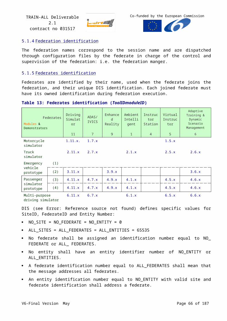
TRAIN-ALL Deliverable 2.1contract no 031517
Co-funded by the European Commission
GMU RTI Error: Reference source not found is implemented in C++, and like XRTI it is only a prototype with limited functionality and it can only handle small federations. The API is intermediate between HLA 1.1 and HLA 1.2. The development of GMU RTI discontinued in 1997, so no future versions are planned.
EODiSP HLA Error: Reference source not found is a more general framework, which also contains a Java implementation of a partial IEEE 1516 RTI. Some basic features are already implemented (create, join, publish, subscribe…) but many features are still missing (Data Distribution Management, Time Management, Ownership Management …). The RTI is still under development, so those features might be implemented in future versions.
rti-s Error: Reference source not found is implemented in C++, and it is only a prototype with limited functionality. While it focuses heavily on Data Distribution Management, many other features (Time Management, Ownership Management…) are missing.
For proper selection of the RTI, agreements among developers of the demonstrators have to be defined. To support the selection of the RTI, table 18 provides a capability overview of the different commercial RTI component available on the market.
6.1.3 Survey of HLA Middleware tools
This Paragraph discusses the requirements and the status of available commercial and open source implementations of HLA middleware software that provides abstractions of the RTI.
By using HLA middleware the task of a federate developer is simplified and the developer can focus on the higher-level functionality of the simulator and the relationship between that functionality and the FOM. This results in more efficient federate development. HLA middleware makes it also easier to port a federate to another (HLA) standard and it can provide common federate functionality in addition to HLA, e.g. pacing to wallclock time.
For federate development, middleware layers on top of the RTI are available. Calytrix Technologies’ SIMplicity, MÄK Technologies’ VR-Link, Pitch Developer Studio, and TNO’s Run-time Communication Infrastructure (RCI) are examples of HLA middleware, mostly supported by code generation.
6.1.3.1 TNO Middleware
The TNO-RTIs are contained in a more general framework Error: Reference source not found (see also § 6.2.1, p.70), the TNO Simulation Architecture (TSA), which consists of the following products:
TSA-RCI: Runtime Communication Infrastructure;
TSA-FMC: Federate Manager Component;
TNO-RTI-1.3 and TNO-RTI-1516;
TSA Codegenerators (RCI and Java);
TSA Gateways (DIS/HLA).
The RCI is the TSA interoperability middleware layer, which provides interoperability services to the components and federates by abstracting the components from the communication between different federates. RCI supports rapid and cost-effective development of both ‘component based’ and ‘traditional’ simulators. The middleware is also very suitable when an interoperability layer is required for existing simulations or tools. The RCI hides complexities of the underlying interoperability standards and enables simulation protocol migration with minimal changes to the functional implementation of the Component or Federate. The RCI is supported by code generators that translate the component’s or federate’s capabilities (specified by a SOM) into easily accessible object-oriented classes in C++ or Java.
V6-Final Version May Page 66 of 140
TRAIN-ALL Deliverable 2.1contract no 031517
Co-funded by the European Commission
There are two different Versions of the RCI:
RCI-1.3 uses the specification HLA 1.3 and is compliant with TNO-RTI-1.3 and DMSO RTI NG 1.3v6.
RCI-1516 uses the specification HLA IEEE 1516 and is compliant with TNO-RTI-1516.
Both versions of the RCI support Federation Management, Declaration Management, Object Management, Time Management and Data Distribution Management.
6.1.3.2 Pitch Middleware
The Pitch Developer Studio Error: Reference source not found is a middleware which provides an easy-to-use API. It provides methods for all HLA/RTI communications, declarations, object registrations and updating, data encoding and decoding, object/attribute reflection and many more. Pitch Developer Studio supports different RTIs and HLA versions, and also DIS bridging is possible. It can be run on different operating systems (Windows XP, Windows 2003, Linux…). It uses the HLA versions 1.3 and IEEE 1516-2000 and supports the programming languages Java and C++.
6.1.3.3 VR-Link Middleware
VR-Link Error: Reference source not found is a networking toolkit for HLA 1.3, HLA IEEE 1516 and DIS. It allows an easy switching between HLA 1.3 and HLA IEEE 1516 without modifying the code. VR-Link can handle dead reckoning, thresholding, coordinate conversions (geocentric, geodetic, UTM, topographic), responding to attribute requests and filtering. Although the VR-Link provides features, such that a direct access to the RTI methods is not needed anymore, it is still possible to access the low level networking details. As programming language, VR-Link uses a C++ interface, and it can be run under different operating systems (Windows XP, Linux…).
6.1.3.4 Calytrix Middleware
Calytrix SIMplicity Error: Reference source not found is an integrated development environment which supports through different stages of simulation design, development and deployment with DIS, HLA 1.3 and HLA IEEE 1516. It assists the design, creation and management of FOMs and of federations. SIMplicity assists to describe the relationships between the federates and the FOM (publish, subscribe …) and to specify the HLA parameters of the federates. It supports the following RTIs:
DMSO RTI1.3 NG6;
MÄK RTI 2.4 (HLA OMT 1.3 or IEEE 1516) and RTI 3.0 (HLA OMT 1.3 or IEEE 1516);
Pitch pRTI1.3 v2.2 and pRTI1516 v2.3 or v3.0;
VTC RTI NG Pro v2.0, v3.0, v4.0.
SIMplicity contains a code generator which produces a running simulation (in Java or C++) out of the business logic. It provides dead reckoning and dynamic data management.
6.1.4 Main Results of the ARCOSIM-HLA study (July 2002)
The ARCOSIM-HLA study that can help TRAIN-ALL concerns the performance overview on the different commercial RTI component available on the market.
This study was entrusted to THALES by the French MoD: the DGA.
This study objective was to evaluate notably the completeness and the performance of the HLA standard in regard to the distributed simulation needs.
V6-Final Version May Page 67 of 140
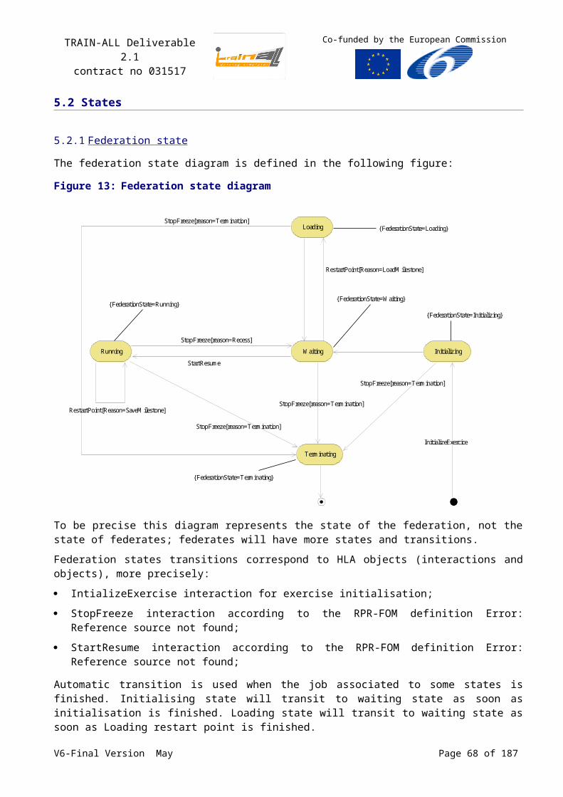
TRAIN-ALL Deliverable 2.1contract no 031517
Co-funded by the European Commission
The standardisation of the interface and exchange in simulation will allow capitalization of models and synthetic DataBases and their reuse in new applications. For example driving simulation is also a basic concern in the land army vehicle course.
The main requirement of the system architecture in simulation as well in lot of other domain is to benefit from distributed computing through standard. Classically simulation even in the driving domain calls for performance in regard to the visualisation and the traffic & vehicle models computing, but also especially in the sharing of complex data as the synthetic DataBase and the scenarios. That’s why the simulation domain pushes hard its own middleware technology mainly with the DIS IEEE 1278 (see Annex B) then the HLA IEEE 1516 (see Annex A) standards, both in used today in most of the (military and yet expensive) simulators.
The Simulation Interoperability Standards Organization (SISO) with 131 members from 25 countries is working hardly on the simulation standardisation
Some architecture simulation frameworks are also proposed as TENA16 or exist as CAE’s STRIVE®17
or THALES’s CIF18 in the main simulators company producers. These frameworks are designed to develop simulators on a common basis, execute the simulation run and facilitate the VV&A validation phase. They are based upon simulation middleware quoted here above (i.e. HLA mainly).
But middleware technology and standard that comes with are nowadays evolving fast from client/ server & P2P technology (CORBA19, DCOM20, Java RMI21) to Web services (SOAP22) and Internet technology. Internet technology seems the absolute basic middleware for CBT dedicated to e-learning.
The following RTIs were studied in 2002:
RTI 1.3NG v6 (09 Septembre 2002) du DMSO;
MäkRTI v2.0.1 de Mäk;
CERTI v3.0.1 de l’ONERA;
pRTI 1.3 v1.22 r1 de Pitch;
pRTI 1516 v2.1 de Pitch;
RTI NG PRO v1.0 de VTC.
These results show in the Table 20 that for the driving purpose of TRAIN-ALL several RTIs are convenient. Each demonstrator (see Table 3, p. 23) can enter a federation of TRAIN-ALL modules. The worse case could be the necessity to federate motorcycles simulators with emergency car simulators among other TRAIN-ALL modules federates. The fact that the driving simulation produce the representation limited to a synthetic bubble around the trainee simplify prohibit the proliferation of played entities among the global simulation represented by the federation. These RTI are used to render the interactions of military entities in the scene: they are designed to play a great number of entities above 500.
16 Test and Training Enabling Architecture (US DoD): for example the early TENA data stream framework was used to provide a video distribution system in MPEG-2 format for military joint training exercise in 2006 (www.tena-sda.org)
17 "The CAE STRIVE® Framework (CAE STRIVE®-SFX) is CAE's next-generation simulation development toolkit and run-time environment. It is an off-the-shelf suite of products that enables networked, distributed simulation application development and deployment through its native object-oriented and high-level architecture (HLA)” www.cae.com
18 Common Infrastructure Framework19 Common Object Request Broker Architecture20 Microsoft Distributed Component Object Model21 Java Remote Method Invocation22 Simple Object Access ProtocolV6-Final Version May Page 68 of 140
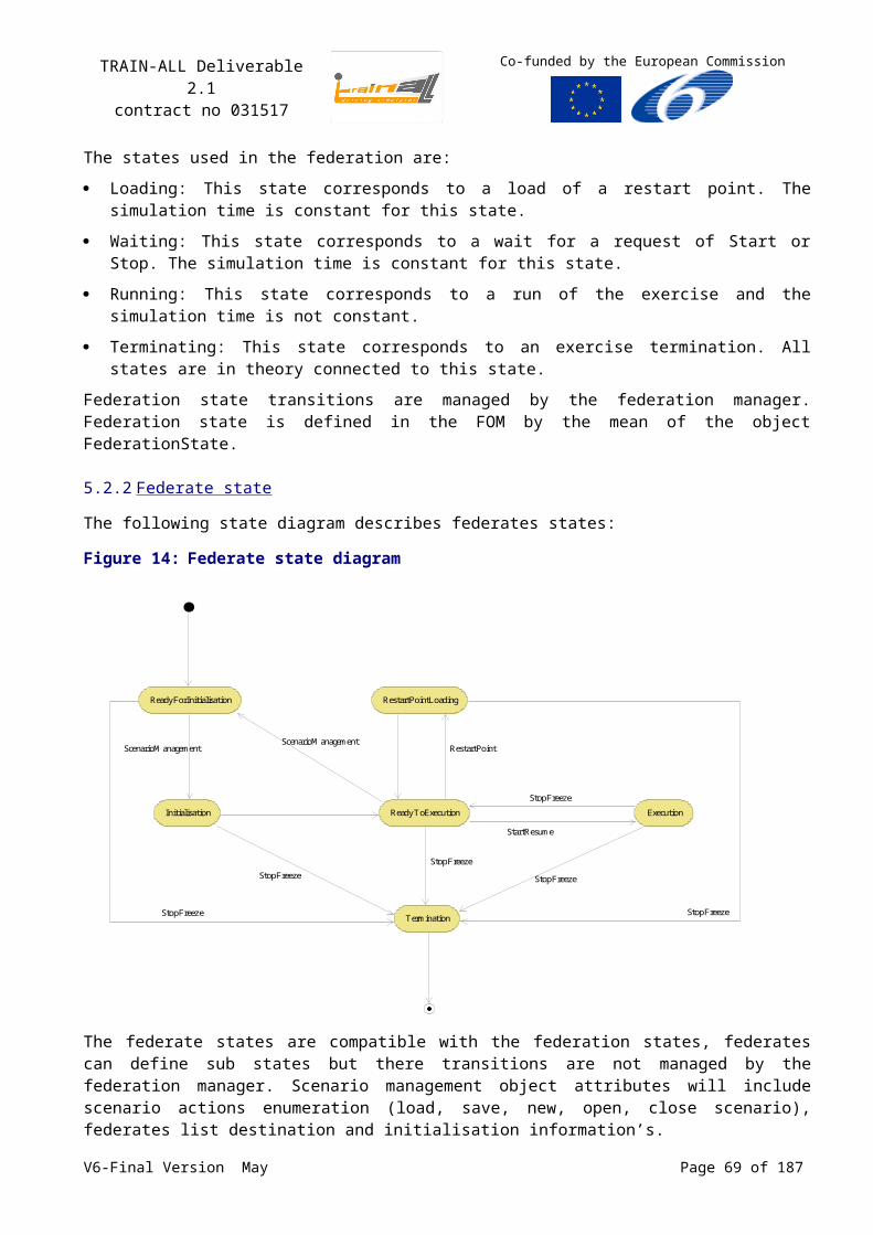
TRAIN-ALL Deliverable 2.1contract no 031517
Co-funded by the European Commission
So the best choice would be to retain a middleware available in the standard 1516. The commercial leaders are now Mäk and Pitch. The cost of these licences (available for 5 federates in the basic configuration) remain expensive per unit ($10,000 with a year of maintenance) but can be decreased to $500 as soon as the amount of licence order will be higher than 20.
Beyond this point, a RTI must be selected according to the tools suite available for the development. The study has made the inventory of the different tools we can expect:
The OMT editor,
The federation configuration management tool,
The Repository,.
The Computer Generated Entities (CGE - in charge of the generation of the traffic),
The Plan View Display (2D),
The 3D Scene Viewer (with a stealth capability),
The federation recording tool (data logger),
The federation audio rendering tool,
The federation manager,
The federation development framework,
The federation tool test,
The federation benchmark tool,
some gateway, bridge or wrapper,
etc..
Table 20: Performance of RTIs analysis
Real TimeConstrained time
Regulated time (as fast as possible)
Constrained timeRegulated time (without
acceleration)
DMSOCould be used within a small entities number among the
federates: the latency is high
Same performance than the VTC RTI
Interesting use for a big entities number among the federates
the latency is prohibitive
Mäk Best choice
Could be used within a small entities number among the
federatesunsuitable otherwise
Could be used within a small entities number among the
federatesunsuitable otherwise
VTC
Could be used within a small entities number among the
federatesthe latency is high
Best choiceInteresting use for a big entities number among the federates
the latency is prohibitive
Pitch 1.3 Same performance than the RTI of Mäk
Good second choice the performance are under the
VTC or DMSO RTI Best choice
Pitch 1516The performance are
enhanced compared to the Pitch RTI 1.3
The performance are enhanced compared to the
Pitch RTI 1.3
Best choice. The performance are enhanced compared to the
Pitch RTI 1.3
CERTICould be used within a small entities number among the
federates (<500)
Could be used within a small entities number among the
federates (<500)
Could be used within a small entities number among the
federates (<500)
6.2Existing HLA Middleware tools among the TRAIN-ALL consortium
Two other HLA middleware tools, i.e. TNO’s Run-time Communication Infrastructure (RCI) [TNO-RCI] and Thales’ NIET 1516 [THALES-NIET], are described in more detail here.V6-Final Version May Page 69 of 140
TRAIN-ALL Deliverable 2.1contract no 031517
Co-funded by the European Commission
6.2.1 TNO-RCI Middleware
The Run-time Communication Infrastructure (RCI) is a middleware layer that provides interoperability services to federates. The RCI extends the interoperability concepts of HLA by providing object based access and data-exchange between federates. The RCI abstracts applications from the intra-federate communication protocols and network hardware. In this way a clear separation between communication aspects and application-specific aspects is established. This enables a federate developer to focus on the required functionality of the specific federate rather than the technical details of the underlying interoperability standard. The RCI is used both on the level of federates and on the level of components. This middleware approach supports rapid and cost-effective development of both 'component based' and 'traditional' simulators. The middleware is also very suitable when legacy simulators or tools need HLA interoperability.
Figure 27: Code Generation based on the FOM or SOM
The TNO code generator uses an Object Model Template (OMT) file as input file to generate HLA interface code. The generated code provides the federate developer with C++ or Java object classes for all OMT object and interaction classes and OMT datatypes. By using the RCI middleware and code generator the task of a federate developer is simplified and the developer can focus on the higher-level functionality of the simulator, i.e. the behaviour logic code, and the relationship between that functionality and the Federation Object Model (FOM) by means of simple glue code. Different types of codegenerators are available: one for the RCI's C++ API and one that supports the RTI's Java API directly. The code generator can be easily extended for a new HLA API or programming language like C#.
The RCI 1.3 is compliant with the DMSO RTI NG 1.3v6, or a compatible RTI like the TNO-RTI and MÄK RTI. The RCI-1516 is compliant with the IEEE-1516 specification and supports compatible RTIs like the TNO-RTI and MÄK RTI. Code generation based on SOM or FOM in OMT 1.3 and IEEE 1516 XML format.
6.2.2 Thales’ NIET 1516
NIET1516 (Normalized Interface Extension Toolkit for HLA1516) is a library intended to facilitate the use of the RTI. It provides an encapsulation of the main HLA services and other functionalities such as Dead Reckoning, management of articulated parts, etc.
V6-Final Version May Page 70 of 140
TRAIN-ALL Deliverable 2.1contract no 031517
Co-funded by the European Commission
Figure 28: NIET1516 library architecture
HLA
NIETGenerator1516
ISSmall_EntityPart(C++ dll) – Articulated
parts
ISSmall_Kinematic(C++ dll) – Dead
Reckoning
ISSmall_Projection (C++ or managed C++
dlls) – Conversion
RTI library
Application (C++ or C#)
NIET1516
(C++ or managed C++ dlls)
Generated code(C++ or managed
C++dlls)
SOM
HLA
NIETGenerator1516
ISSmall_EntityPart(C++ dll) – Articulated
parts
ISSmall_Kinematic(C++ dll) – Dead
Reckoning
ISSmall_Projection (C++ or managed C++
dlls) – Conversion
RTI library
Application (C++ or C#)
NIET1516
(C++ or managed C++ dlls)
Generated code(C++ or managed
C++dlls)
SOM
NIET1516 consists of two different blocks of code:
NIET and NIET_HLA libraries: these libraries implement the generic mechanisms of NIET:
NIET library constitutes the entry point; it includes various interfaces (for generic objects and interactions, federate, etc.).
NIET_HLA library implements the previous interfaces; it encapsulates the main HLA services (Federation Management, Declaration Management, Object Management, Ownership Management, Time Management but not Data Distribution Management), it ensures also serialization (Big Endian and Little Endian), masks the complex use of the RTI API by allowing the management of HLA objects and interactions instead of attributes or parameters, offers Dead-Reckoning services, etc.
Generated code: The generated code describes the specific information manipulated by the federate. This code is generated from the SOM file by using a tool called NIETGenerator. From the SOM file, NIETGenerator generates a solution and two projects. These projects leads to two libraries: the first one, called Som, constitutes the entry point and includes the interfaces (accessors to specific objects and interactions); the second one, called Som_HLA, implements the interfaces.
Moreover, NIET uses three dlls as plugins:
ISSmall_Projection: allows data conversion;
ISSmall_Kinematic: ensures Dead Reckoning on the kinematic of entities;
ISSmall_ EntityPart: ensures Dead Reckoning on articulated parts.
Finally, NIET1516 is available in C++ and managed C++. So, it can be used both by C++ and C# applications.
6.3HLA tools description
Besides the RTI software, which is an essential component to run an HLA federation and available from several commercial and non-commercial sources (see Section 6.1, p63), other tools are available to support HLA federation development.
For SOM and FOM development several OMT editors are available, e.g OMDT from Aegis and OMT Visual from Pitch. With these tools HLA Object models can be created and maintained in an effective way. Note that the OMDT versions made by Aegis for DMSO up to 2002 were free available.
To capture, inspect and replay simulation data, logging tools are available from Pitch and MÄK Technologies.
V6-Final Version May Page 71 of 140
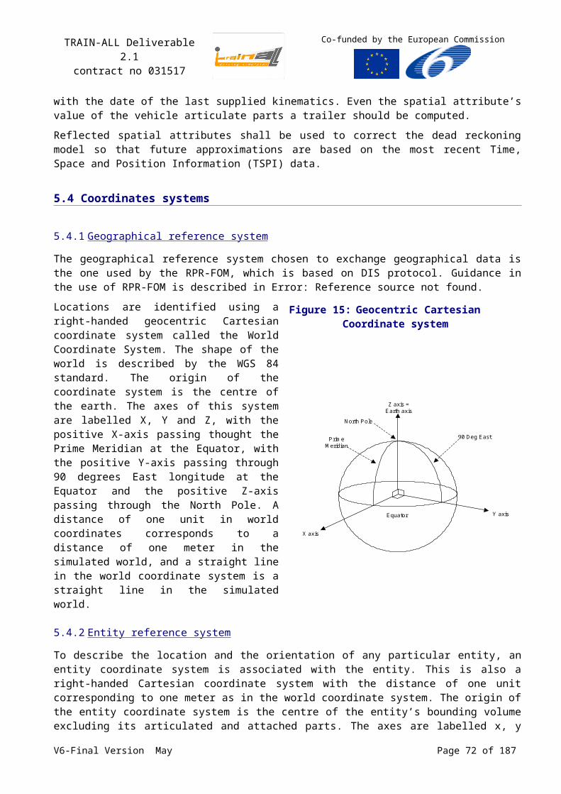
TRAIN-ALL Deliverable 2.1contract no 031517
Co-funded by the European Commission
6.4Survey of tools
The commercial products mentioned above can be found at the following websites. Of course, the list is not exhaustive.
Table 21: Commercial HLA Middleware and ToolsAegis OMDT http://www.aegistg.com/AEgisTechnologiesProducts_LabWorks2.html
Calytrix Technologies
SIMplicity http://www.calytrix.com/siteContent/SIMplicity/intro.php
MÄK Technologies
VR-Link http://www.mak.com/products/vrlink.php
Data Logger http://www.mak.com/products/datalogger.php
Pitch Visual OMT http://www.pitch.se/products/visual-omt/visualize-and-collaborate.html
Developer Studio
http://www.pitch.se/products/pitch-developer-studio/pitch-developer-studio.html
Recorder http://www.pitch.se/products/recorder/record-analyze-and-playback.html
V6-Final Version May Page 72 of 140
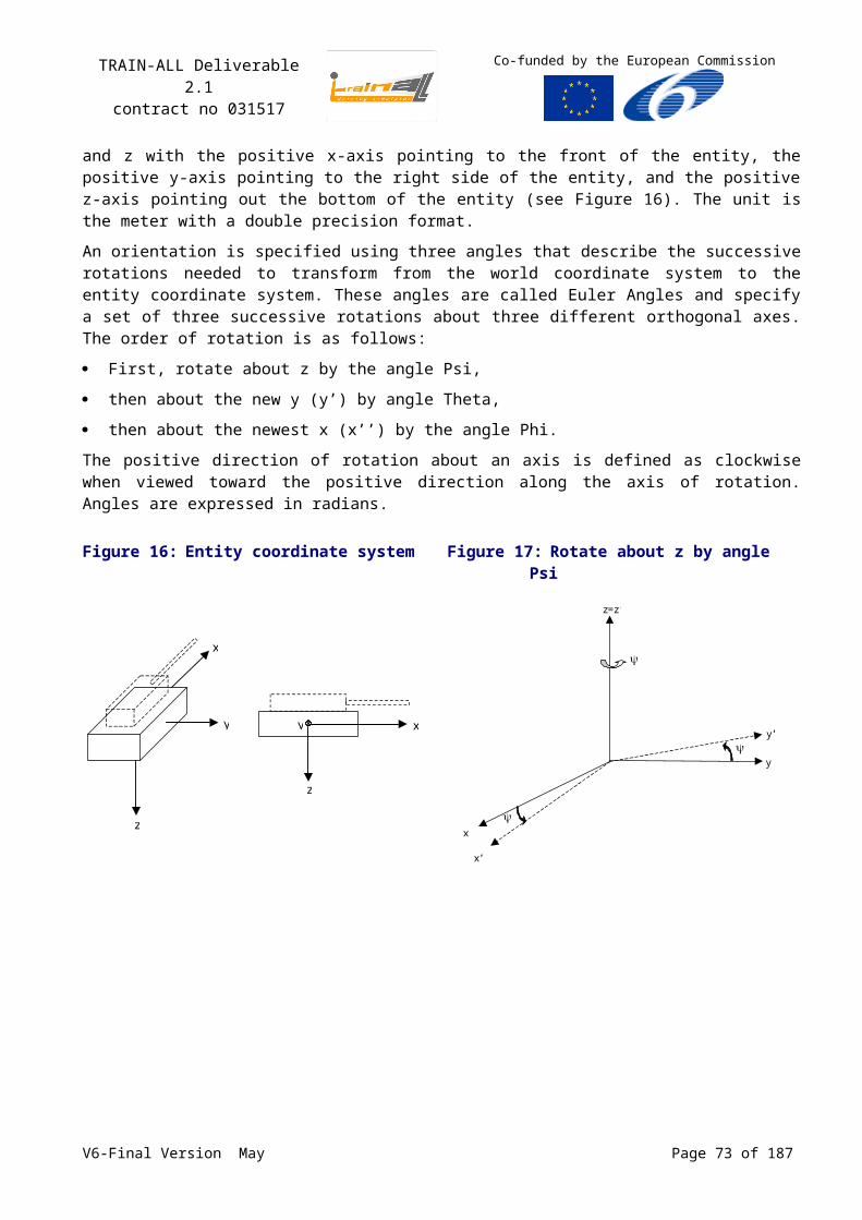
TRAIN-ALL Deliverable 2.1contract no 031517
Co-funded by the European Commission
7 Interoperability of training and assessment scenarios
Three different views on interoperability of training and assessment scenarios can be adopted. First, interoperability could mean that in a given driving simulator training and assessment are based on the same scenarios. Second, different simulators could be able to present the same training and assessment scenarios to the student. Third, it could mean that simulator based training and assessment scenarios are interoperable or integrated with Computer Based Training or Testing. This chapter will address each of these three views on interoperability.
We will show that each view may benefit from the combination of two standards: SCORM, the standard for Computer Based Training and its associated standards, and HLA, the standard for interoperability of simulations and simulators, and the associated standards. The next sections will primarily focus on SCORM, and approach standardization from an instructional perspective. SCORM may be of great value when discussing lessons, learning content and testing in simulators, and when integrating simulation/simulators and CBT.
7.1Training and assessment in a single simulator
In a single simulator, interoperability of training and assessment is rather straightforward, as training and assessment go hand in hand. Adequate training requires that students are presented with realistic traffic situations, are supported with the correct type of instruction, and that their performance is assessed reliably and valid. A simulator based test can be based on the same traffic situations, does not require instruction, but capitalizes on reliable and valid performance assessment. In both training and assessment, performance should be measured with the same measures and rated with identical standards.
There is a lot to say for a simulator based assessment of traffic participation skills. Candidates are judged in an environment that closely resembles the actual driving environment, allowing a high validity. The traffic environment can, in contrast to the real world, be controlled at will. Thus a carefully balanced and uniform test can be presented to all candidates. Since one never knows what situations will be encountered during a practical driving test, a simulator based test has a point in its reliability.
A simulator based test has some special requirements. It cannot be based on the fixed routes with predefined traffic situations that are presented in many training simulators. Such routes would in no time be described in detail on the internet, and the test would be useless. A test should be composed of a set of clearly defined test items that can be selected from a huge database of test items and that can be presented in random order. In that sense, the concept of such a test is similar to that of an adaptive training, where traffic situations can be selected at will to fit the training needs of an individual student. In both cases, there’s a database of tagged scenarios, in which a selection can be made to compose a training session or a test. Such an approach will allow for adaptive testing, in which student performance is a variable when selecting test items with a specific difficulty. This generally reduces testing time with about 40%.
A database with tagged scenarios that can be presented at will to the student is also convenient for training. The advantages span different levels. First and foremost, it will allow for adaptive training, in which students are presented with the type of situations and the instruction that corresponds with their individual learning curve. Control over the selected scenarios could be with the system, automatically selecting new scenarios. However, it could also be with the simulator instructor, the practical driving instructor or the student him or herself. A database with individual scenarios will also have benefits for simulator developers and researchers. It is much more convenient to pinpoint errors and anomalies within an individual traffic situation than in a complete lesson. It may also help discussing
V6-Final Version May Page 73 of 140
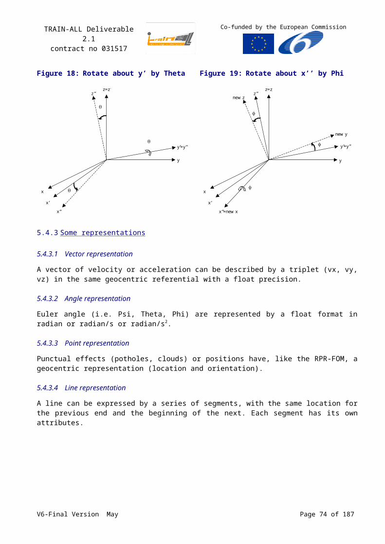
TRAIN-ALL Deliverable 2.1contract no 031517
Co-funded by the European Commission
performance measurement and setting assessment criteria if we regard one single situation in traffic at a time.
A single simulated traffic situation that is presented to the driver can be regarded as a ‘learning object’: the smallest unit that can be presented to the driver comprising all the information required for training. Learning objects have many characteristics that come handy when discussing interoperability of training and assessment scenarios:
Learning objects are a new way of thinking about learning content. Traditionally, content comes in a several hour chunk. Learning objects are much smaller units of learning.
Are self-contained – each learning object can be taken independently.
Are reusable – a single learning object may be used in multiple contexts for multiple purposes.
Can be aggregated – learning objects can be grouped into larger collections of content, including traditional course structures.
Are tagged with metadata – every learning object has descriptive information allowing it to be easily found by a search.
Test items can be considered along similar lines: they can be regarded as the smallest self contained unit within a test, designed for reusability, can be aggregated, and can be tagged with metadata.
SCORM (see Annex H, p.117) and SCORM related standards like the Question and Test Interoperability standard have extensive definitions for tagging and navigating learning objects and test items.
7.2Training and assessment on different simulators
Although they may appear quite similar at first glance, different driving simulators can be based on fundamentally different modelling principles. Traffic, logical databases, virtual environments, scenario languages, performance measurement and assessment, they will all differ between different software suites in use with the simulator manufacturers. The HLA standard, and the associated standards in the simulator domain, will make an important contribution to interoperability and standardization of such dissimilar systems.
Interoperability can also be addressed on a higher level. A contribution to interoperability of training and assessment can be made by standardizing the tools that manage these processes. Thus, when switching to a different simulator, the school could keep their lesson structure, the didactical philosophy contained within them, and the learner management systems that support the learning process on the simulator.
The HLA standards do not provide much guidance here. We will need to take a look at CBT standards like SCORM and QTI, and at the Learning Management Systems (LMSs) associated with these standards. CBT has been around for decades, and interoperability and reuse of learning objects have subject of research for many years. The current generation of LMSs combine many interesting features such as content management (repository, version control, usage stats), Student progress tracking, scheduling and notification, Facility scheduling, Deliver training, Reporting, User Forums, Chat, Blogs, Glossaries etc.
SCORM and QTI standards are targeted at web-based CBT and are not designed to be used with simulations and simulators. However, they are currently being combined with simulator based standards like HLA, in the SCORM-Simulation Interface Standards workgroup of the Simulation Interoperability Standards Organization (SISO). This combination will pave the way for using standardized Learning Management Systems and interfaces on (driving) simulators of different manufacturers. Also, SCORM and QTI provide standardized descriptions of lessons, lesson content, didactical methods, sequencing and navigation, and other ‘meta’ aspects of training with advanced
V6-Final Version May Page 74 of 140
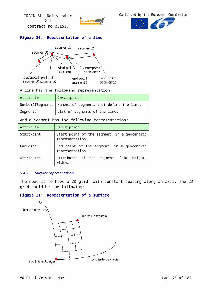
TRAIN-ALL Deliverable 2.1contract no 031517
Co-funded by the European Commission
learning systems like CBT, that would reduce the current disparities on these concepts in the simulator community.
7.3Interoperability of CBT and simulation
Although CBT and simulation originate from different domains, hybrid applications are emerging. Typical CBT content such as text, pictures, flash animations and movie clips are presented before or during a lesson or assessment in the simulator, and we see simulations appear in Web-based CBT environments. Combining CBT and simulations will provide a richer learning experience to the student. Students can be presented with relevant instruction and feedback, and with assessments, questionnaires. It would be convenient if such disparate didactical content could be managed from within a single application.
Within TRAIN-ALL the simulators that will be used support in many cases the insertion of platform material. In computer based tools, a number of standards are used for creating reusable content for training and testing purposes, such as SCORM. These standards often apply to simulated traffic situations that might be presented as learning objects to the users. Even if the simulated traffic solutions are not compatible with the SCORM standard itself, input file formats are typical Sharable Content Objects, namely audio files (WAV and MP3), GIF images and JPEG files, while in some cases (e.g. the GREEN DINO simulator) xml documents and HTML fragments can be inputted in a simulation. However 3D objects appearing in simulations are not yet supported by the SCORM. Forterra Systems, is currently researching methods for enabling interoperability, accessibility and reusability of Sharable Content Object Reference Model (SCORM) compliant with learning content in 3D virtual worlds. [http://scormwatch.typepad.com/]
In the reverse case of inputting elements from the simulation into multimedia training platforms simulators should be able to export, apart from log files, multimedia objects either compatible to SCORM or file formats that could be easily converted to SCORM supported types of data, namely AVI, JPEG, GIF, WAV, MP3. There is a large number of commercial converters to JPEG, to GIF as well as to WAV and MP3, available in the market, allowing thus the export of SCORM compatible data from simulations. Videos and snapshots can be then imported in multimedia training tools.
These actions will facilitate the development of a continuous learning experience, in which (web-based) CBT and simulator lessons are seamlessly integrated. Merging SCORM and HLA standards is of fundamental importance in this area as well.
7.4Interoperability between ADAS/IVICS and simulators/ CBT tools
7.4.1 Introduction
The last two decades more and more electronic devices are implemented into modern motor vehicles, such as engine management systems, active suspension, ABS, cruise control, airbags, in vehicle navigation systems. All these systems do not mean increased safety and comfort while driving but also a more economic and environmental friendly driving approach. All those systems and their respective sensors need to communicate with each other and exchange information; however the point-to-point interconnection of so many sensors and devices to such extent had no longer been feasible. As such serial bus systems have been adopted and introduced since already the late 1980s fulfilling the special requirements needed for vehicles.
Typical examples of vehicle bus systems are A-BUS from Volkswagen, VAN or Vehicle Area Network, from Peugeot and Renault, J1850 from Chrysler, General Motors and Ford and CAN by Robert Bosch GmbH. However the most widely used and supported by the automotive industry in the EU is the CAN (Controller Area Network) protocol. CAN is internationally standardized by the International
V6-Final Version May Page 75 of 140
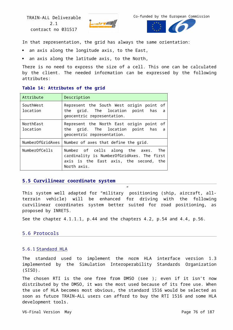
TRAIN-ALL Deliverable 2.1contract no 031517
Co-funded by the European Commission
Standardization Organization (ISO) and the Society of Automotive Engineers (SAE). The CAN protocol uses the Data Link Layer and the Physical Layer in the ISO - OSI model.
CAN is a computer network protocol and bus standard with an open, linear structure with one logic bus line and equal nodes. The number of nodes is not limited by the protocol. The devices that are connected by a CAN Network are typically sensors, actuators and control devices through a host-processor and a CAN Controller. In the CAN protocol, the bus nodes do not have a specific address, on the contrary the address information is contained in the identifiers of the transmitted messages, indicating the message content and the priority of the message. The number of nodes may be changed dynamically without disturbing the communication of the other nodes.
A CAN network can be configured to work with two different message (or “frame”) formats: the standard or base frame format (known as CAN 2.0 A) and the extended frame format (known as CAN2.0 B) as seen below.
Figure 29: CAN Message Formats
The only difference between the two formats is that the “CAN base frame” supports a length of 11 bits for the identifier while the “CAN extended frame” supports a length of 29 bits for the identifier – made up of the 11-bit identifier (“base identifier”) and an 18-bit extension (“identifier extension”).
7.4.2 Composition of the data frame
The frame formats supported in CAN are:
Data frame: a frame containing node data for transmission;
Remote frame: a frame requesting the transmission of a specific identifier;
Error frame: a frame transmitted by any node detecting an error;
Overload frame: a frame to inject a delay between data and/or remote frames;
Interframe space: a frame to separate a preceeding frame (of whatever type) from a following Data or Remote Frame.
V6-Final Version May Page 76 of 140
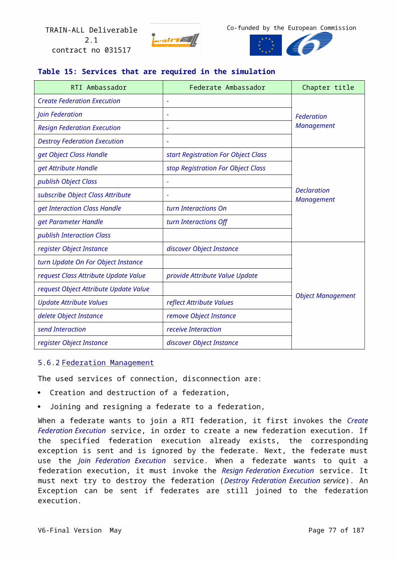
TRAIN-ALL Deliverable 2.1contract no 031517
Co-funded by the European Commission
Figure 30: Data Frame Format
A "Data Frame" is generated by a CAN node when the node wishes to transmit data. The Standard CAN Data Frame is shown above. The frame begins with a dominant Start Of Frame bit for hard synchronization of all nodes. The Start of Frame bit is followed by the Arbitration Field consisting of 12 bits:
The 11-bit Identifier, which reflects the contents and priority of the message,
The Remote Transmission Request bit.
The Remote transmission request bit is used to distinguish a Data Frame (RTR = dominant) from a Remote Frame (RTR = recessive). The next field is the Control Field, consisting of 6 bits. The first bit of this field is called the IDE bit (Identifier Extension) and is at dominant state to specify that the frame is a Standard Frame. The following bit is reserved and defined as a dominant bit. The remaining 4 bits of the Control Field are the Data Length Code (DLC) and specify the number of bytes of data contained in the message (0 - 8 bytes). The data being sent follows in the Data Field which is of the length defined by the DLC above (0, 8, 16... 56 or 64 bits). The Cyclic Redundancy Field (CRC field) follows and is used to detect possible transmission errors. The CRC Field consists of a 15 bit CRC sequence, completed by the recessive CRC Delimiter bit. The next field is the Acknowledge Field. During the ACK Slot bit the transmitting node sends out a recessive bit. Any node that has received an error free frame acknowledges the correct reception of the frame by sending back a dominant bit (regardless of whether the node is configured to accept that specific message or not). From this it can be seen that CAN belongs to the "in-bit-response" group of protocols. The recessive Acknowledge Delimiter completes the Acknowledge Slot and may not be overwritten by a dominant bit. Seven recessive bits (End of Frame) end the Data Frame (CAN).
For ADAS/IVICS data to be fed into a simulation following a standardized solution, the data field of the data frame could be isolated through a software gateway and imported into the objects of the TRAIN-ALL standard Datamodel. As such a standardized solution based HLA can be applied.
V6-Final Version May Page 77 of 140
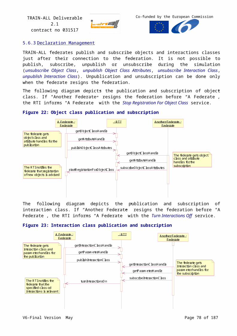
TRAIN-ALL Deliverable 2.1contract no 031517
Co-funded by the European Commission
8 Interoperability of SCORM and HLA
8.1Current research
Currently, there are initiatives to merge SCORM and HLA, to allow the SCORM standard to be used for enhancing the interoperability of learning content on the simulator (e.g. in the SCORM – Simulator study group of the Simulation Interoperability Standards Organization, see www.sisostds.org for information and a repository of the papers discussed below). The study group has organized several workshops and has invited several partners to contribute with position papers. These papers reflect the different viewpoints that partners have on the integration of SCORM and HLA standards. We have not found any literature combining QTI to HLA or MSDL to SCORM. However, the QTI standard is web-based, just like SCORM, and these two standards are converging. MSDL is simulator based and related to HLA. When investigating SCORM-HLA we are looking at the critical interface between these two domains, and all the standards that they comprise.
Marshall and Bray (2006), from the Joint ADL Co-lab describe some of the goals of the ADL initiative in relation to the use of simulators and simulations. ‘The goal of the ADL Initiative is to integrate simulations into the workflow of distributed learning and reduce barriers to effective implementation in support of learning and performance enhancement'. Such systems may include the following:
Using Sharable Content Objects (SCOs) (non-simulation) for instruction and remediation to build the student’s knowledge.
Using simulation for the student to practice skills.
Capturing at least a small set of student interactions with the simulation, and sending results back to the Learning Management System (LMS), to adapt the learning using SCORM sequencing rules, and to assess the student.
They describe some of the barriers integrating simulation and SCORM. Among other they raise the following considerations:
For a simple virtual simulation used in a single student context, is the SCORM data model sufficient to describe meaningful student interactions? What would be an optimal assessment algorithm?
How should we use the data collected to create meaningful, adaptive web-learning with remediation?
For After Action Review (AAR), how do we define, capture and analyze the data that is typically involved?
On a more detailed level, how should a simulation be related to a SCO (content)?
How should a simulation be related to an LMS (system)?
How should content be integrated into a complex simulation?
The paper briefly describes some of the prototype projects integrating SCORM and HLA that ADL has funded or collaborated in (see www.adlnet.org/technologies/simulations).
V6-Final Version May Page 78 of 140
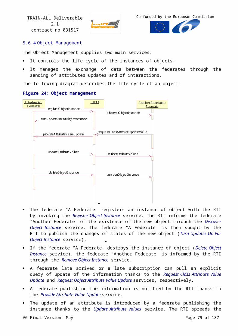
TRAIN-ALL Deliverable 2.1contract no 031517
Co-funded by the European Commission
8.1.1 SAIC
Morse (2006) from SAIC takes a Web based perspective on integrating SCORM and HLA., and sums some of the benefits of integrating HLA and SCORM:
The student engages in the proven instructional paradigm of “learning followed by doing.”
The system automatically performs intelligent, real time assessment of the student’s interaction with the simulation and feeds the results directly back to the learning management system, enabling focused, individualized remediation.
Automated remediation reduces reliance on instructors for one-on-one student assessment.
A legacy simulation may be made available without moving its dedicated hardware or trying to create a new installation on potentially rare hardware, both very expensive propositions.
The simulation can stay home-based with its technical support and configuration management.
Content can also be home-based with its technical support and configuration management.
Simulations and training are guaranteed to be absolutely up to date when delivered to the student.
The warfighter can access this rich training environment while deployed and while home based.
The web-based protocols employed allow operation through most firewalls.
She continues with an analysis of the ‘daunting challenges in delivering SCORM content via an RTI’. These include developing an RTI with less overhead and overcoming security issues between mostly military proprietary simulators and simulations and the Web-based interoperable SCORM access model. This situation may also change as a result of the other changes proposed for the IEEE 1516.1 standard, the inclusion of Web Services Definition Language (WSDL) APIs.’
8.1.2 Stottler Henke Associates
Frank (2006) from Stottler Henke Associates sums up some of the extensions that are required in SCORM to be able to manage simulator/simulation based SCOs:
Extend the SCORM content aggregation model if necessary to enable discovery of SCOs based on simulation-specific attributes.
Extend the SCORM run-time API to enable the saving of larger amounts of data than the current bookmarking support to save simulation state to enable suspension and resumption of simulation scenarios.
Enable the SCO to return student performance scores along many learning objectives that are automatically assessed by the SCO. Remove the assumption that a single overall score determines whether the SCO has been mastered. Rather, each simulation-based SCO can potentially teach, assess, or expose students to a large number of topics and learning objectives.
Enable LMSs to select/configure learner-appropriate SCOs based on a complex student model (exposure to and proficiency at many different skills or learning objectives, other learner preferences).
‘New SCORM support for simulations should enable a LMS to select, configure, and launch a SCO for a learner that enables the learner to run a simulation scenario. A simulation scenario specifies the learner’s goals, a set of objects in the simulation, and their appearance, interactions and behaviours. During the scenario, the learner interacts with the simulation by performing user interface actions via the simulation user interface. Simulation behaviours define how the simulation responds to user actions, the passage of time, and interactions among the simulation objects. Potentially, a course could select from or generate at run-time very large number of possible scenarios. Scenario configuration data can be provided by the LMS to the SCO that executes the scenario via launch data or launch parameters that contain the scenario configuration data. SCO launch parameters and V6-Final Version May Page 79 of 140
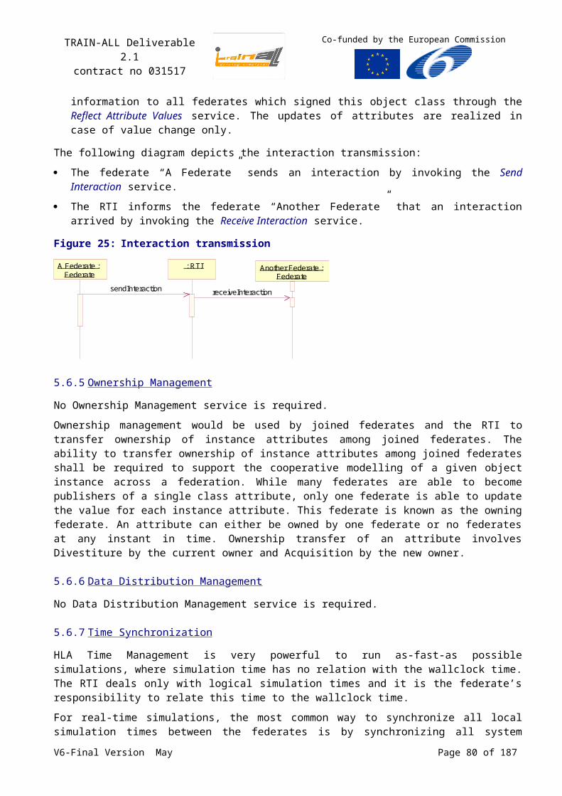
TRAIN-ALL Deliverable 2.1contract no 031517
Co-funded by the European Commission
launch data can optionally be used to specify the scenario configuration parameters or identify a configuration (e.g., stored in a file and located via URL). It is also desirable that the SCO be able to receive from the LMS data about the student, such as his or her proficiency at or exposure to many different skills or learning objectives. Possible mechanisms for this include receiving this student data as launch data or enabling the SCO to query the LMS for student data.’
8.1.2.1 Evaluating and Reporting Learner Performance
Like traditional SCOs, a simulation-based SCO must be able to evaluate and report the learner’s performance automatically. However, in contrast with traditional SCOs, during the course of running a single simulation-based SCO, the learner may be presented with many situations (or changes to an initial situation) that may require the learner to apply a variety of knowledge and skills. At minimum, this requires the ability to report the learner’s performance along potentially many possible skills or learning objectives, rather than just a single aggregate score. Because different learners may perform different actions within the same scenario, resulting in different execution paths, the set of learning objectives evaluated and reported by a given scenario may differ across simulation runs. Because the number of possible student solutions or sequences of actions is so large, assessing student performance during simulation scenarios may require more sophisticated algorithms than are usually employed by traditional SCOs. Authoring/development and run-time tools for automated student performance during simulations, such as those embedded within intelligent tutoring systems, may be useful for reducing development effort, so its desirable that scenario players be able to integrate with these automated assessment tools (not sure what the impact of this would be on the SCORM architecture.)
In addition, it would be desirable to also provide the ability for the SCO to report fine-grained learner actions performed during the scenario to support logging, replay, or detailed after-exercise debriefing/after-action review.
8.1.2.2 Encouraging Reuse of Simulation Objects
It is desirable to facilitate and encourage the development and sharing of reusable SCORM-compliant simulation objects to lower the cost of developing simulations. Reusable simulation objects (SCORM assets?) could include software that simulates real-world objects, non-player characters, or other simulated entities. It can also include software that evaluates learner performance and/or provides automated instruction before, during or after the scenario (e.g., intelligent tutoring). We expect that a common way of reusing such software would be to integrate software objects with the scenario player or embed them within the player. The specific details of how various scenario players integrate with simulation objects is outside the scope of the SCORM specification. However, we expect that each different scenario player would define a message protocol or programming interface that embedable simulation objects would need to comply with.
8.1.3 Boeing
The Boeing company (Darque, Biddle, Perrin, 2006) has implemented several prototypes to interface simulations with SCORM-Compliant training. ‘Two of these approaches utilize DIS or the HLA as an interface mechanism between the assessment module and the simulation. Performance assessment sent to the Learning Management System (LMS) using the SCORM is key to each of these implementations. The major differences in the two major approaches outlined in this paper are (a) how the training initializes the simulation – via HLA or file system, and (b) when and “where” the student performance is assessed – in real-time by a virtual instructor in the SCORM-compliant training, or after-action, by a debrief tool’.
V6-Final Version May Page 80 of 140
TRAIN-ALL Deliverable 2.1contract no 031517
Co-funded by the European Commission
8.1.3.1 Method 1: the HLA/SCORM Prototype
This prototype uses a simulated virtual instructor (SVI) in the SCORM-compliant training to evaluate and give performance feedback to the student in real-time. The interface is bi-directional and uses the HLA to send initialization data to the simulation and to send student performance data to the SVI for evaluation, see Figure 31 and Figure 32.
Figure 31: GUI of the LMS
Figure 32: LMS interfacing with Flight Sim
8.1.3.2 Method 2: Boeing Fighter Training Centre Demonstration
This demonstration featured technology that used DIS to automatically assess student performance in an F/A-18 weapon system trainer (flight simulator) and report the assessment to a COTS LMS. This involved complex performance measurements, suited for a mission that consisted of several complex and semi-complex manoeuvres including taking off, climbing, turning, selecting weapon, operating the mission computer, and launching a missile.
They used a separate SCORM compliant web-based training simulator, equipped with a COTS joystick and throttle to prepare the students for the mission, using SCORM Sequencing and
V6-Final Version May Page 81 of 140
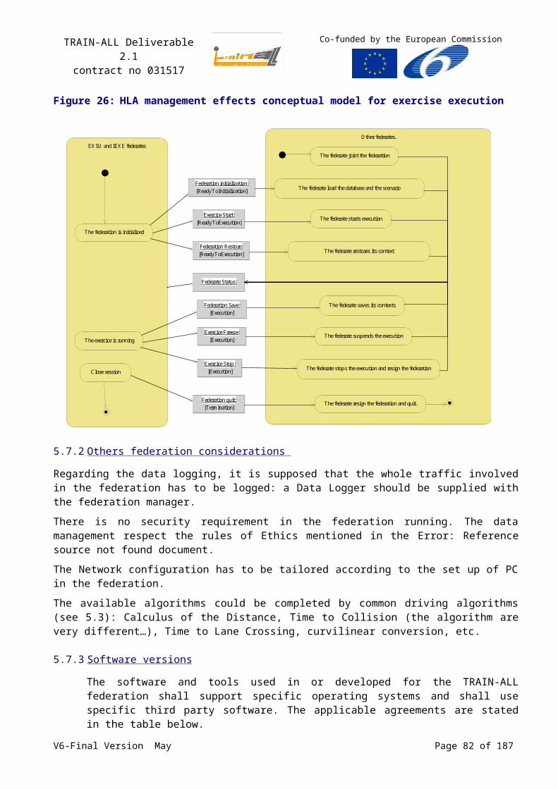
TRAIN-ALL Deliverable 2.1contract no 031517
Co-funded by the European Commission
Navigation to adapt the content to the student and only presented the material that the student would need for the mission it selected for them.
Subsequently the student was trained in a flight simulator. Since they were using an unmodified simulator which did not use DIS or HLA to initialize the simulator, the LMS could not communicate directly to the simulator. That was solved using an initialization file on a shared directory. This enabled the instructor to simply load the file named after the student in order to initialize the simulation(s) to the proper mission and conditions for the student. After finishing the simulated mission, the simulator returns the student’s performance data to the LMS. The LMS debriefs the mission, and may select a new mission to enhance or remediate student performance using SCORM sequencing rules.
Figure 33: LMS integration
8.1.4 Engineering and Computer Simulations
Smith and Dubuc (2006) from Engineering and Computer Simulations take a different route to integrating SCORM and Simulations and describe a proof of concept integrating the Navy’s SCORM compliant Integrated Learning Environment (ILE) and Delta 3D, the Navy’s simulation engine.
Smith and Dubuc focus on new ‘smart client’ technology which aims to bridge ‘thick clients’, the traditional software packages and simulations running on your pc, and ‘thin clients’, browser based applications such as a SCORM compliant LMS. A smart client is a hybrid, which can be stored on a web server, and installs on user machines on-demand, and keeps itself updated regularly downloading new or revised components. They feel smart clients may help to facilitate the integration of simulations into an LMS. ‘It may allow learners to seamlessly launch into a training simulation from within a web-based training module and provide a means for the simulation to return assessment data back to the LMS. In addition, by automatically installing and caching the necessary simulation components locally and on-demand, a smart client application can provide an immersive training experience to the learner’. The smart client downloads, installs and maintains a (large) simulation package on the user’s computer, on which it is subsequently addressed by the LMS during run-time.
Smith and Dubuc share some insights on communicating performance measures between simulator and LMS. ‘In order for student performance to be tracked inside a simulation, the data communicated
V6-Final Version May Page 82 of 140
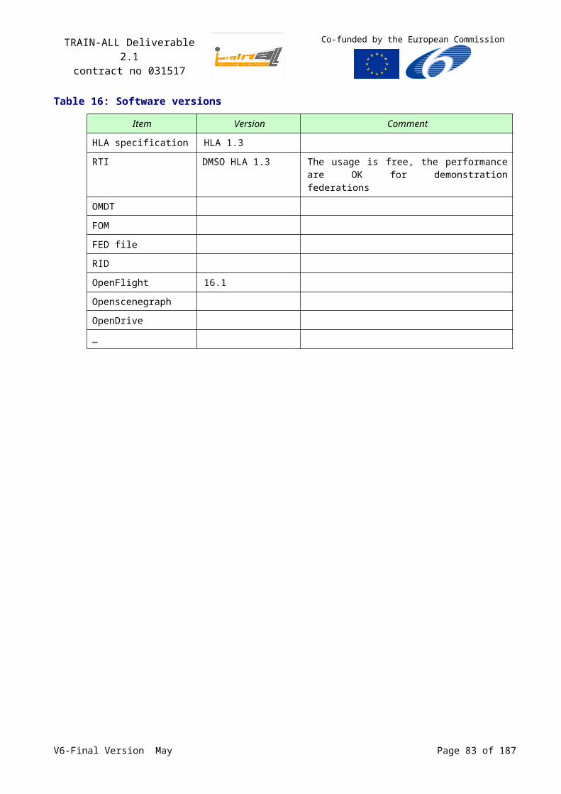
TRAIN-ALL Deliverable 2.1contract no 031517
Co-funded by the European Commission
to the LMS must be confined to the assessment data model that SCORM provides. Generally speaking, each SCO can contain a number of “objectives”, and learner progress toward each objective can be tracked according to basic data values such as completion status, success status, and score. Thus, while a simulation scenario may track many assessment variables internally, it needs to be able to combine these variables into data values that an LMS is able to understand.’ In this process ‘it is important to differentiate between the various types of messages that will be produced by the simulation, processed by the assessment module, and passed on to the LMS:
1. Simulation Events are raised by simulation code and are determined by the designers to be “relevant” markers of something important happening. These events may be generated by simple user actions, such as “user pushed button”, or can encapsulate more complex concepts that capture the interaction between simulation objects with other simulation components such as “time” and “state” variables within the simulation. The complexity of what constitutes a simulation event will ultimately be determined by instructional designers and a simulation’s developer.
2. Tasks are defined in the assessment module (i.e. outside of the simulation code), and represent a “unit of work” defined from a list of simulation events available within a simulation, A method of capturing and naming each simulation needs to be developed to publish all of the events within each simulation that are necessary to satisfy each task. These events are processed through a rule-based assessment module that has the capability to apply each event to a model that tracks the state of each task (and ultimately, each training objective). Because tasks are defined outside of the simulation, they can be created and modified by course designers without having to change and re-compile any code.
3. Objectives are simply top-level tasks (i.e. tasks that are not a sub-task of anything else). Conceptually, however, an objective differs from a task in that it represents the achievement of a prescribed learning goal. As the simulation unfolds, the assessment module will communicate the status of learner progress toward each objective to a Learning Management System. Each simulation scenario may contain a number of objectives.
In summary, the assessment process is broken into logical components. The simulation raises simulation events as the user interacts with it. The assessment module listens to these simulation events, and uses them to track a learner’s progress toward completion of defined tasks. An assessment data model is used to combine events and tasks in a hierarchal manner to form more complex tasks, which ultimately culminate in one or more objectives. As a learner completes the training objectives, the assessment component communicates this information to the LMS.’
Engineering and Computer Simulations have built a proof of concept to show the potential of a smart-client based integration of a SCORM compliant LMS and a delta3D. Figure 34 shows a schematic overview of this system. The paper provides many details on this integration.
V6-Final Version May Page 83 of 140
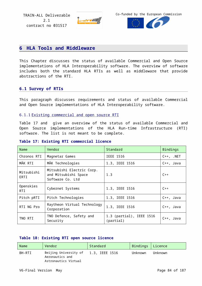
TRAIN-ALL Deliverable 2.1contract no 031517
Co-funded by the European Commission
Figure 34: A schematic overview of an integration of a SCORM compliant LMS and the Delta3D simulation engine using smart client technology
8.1.5 Intelligent Automation Inc.
Haynes, Marshall, Manikonda and Maloor, (2004) describe an architecture for integrating SCORM-Compliant Instruction with HLA-Compliant Simulation (SITA). They have developed a prototype to evaluate the feasibility of such an architecture. In the Air Traffic Management domain, the HLA compliant Collaborative Regional Flow Control Decision Support Tool was linked to a browser based Learning Management System using an RTI-SCO interface.
Haynes and Bukai (2006) address the problems that arise when simulations are ‘embedded’ within a single SCO. If a learning experience would span multiple SCOs, the simulation would have to be un- and reloaded each time. Their goal is to divide simulation based instruction into small instructionally discrete SCOs, while maintaining a persistent simulation presentation. They describe a solution that fits within the requirements set by the current SCORM standards, using a plug-in that allows the simulation to persist through the run-time of multiple SCOs.
8.2TNO SimSCORM
TNO has developed a generic platform, which can be used in various simulation environments. Except that the simulation is HLA compliant and that its object model is described according to the HLA standard, no assumptions were made about the content of a specific simulation. Furthermore, no assumptions were made about the content or design of a specific LMS, except that it is compliant to V6-Final Version May Page 84 of 140
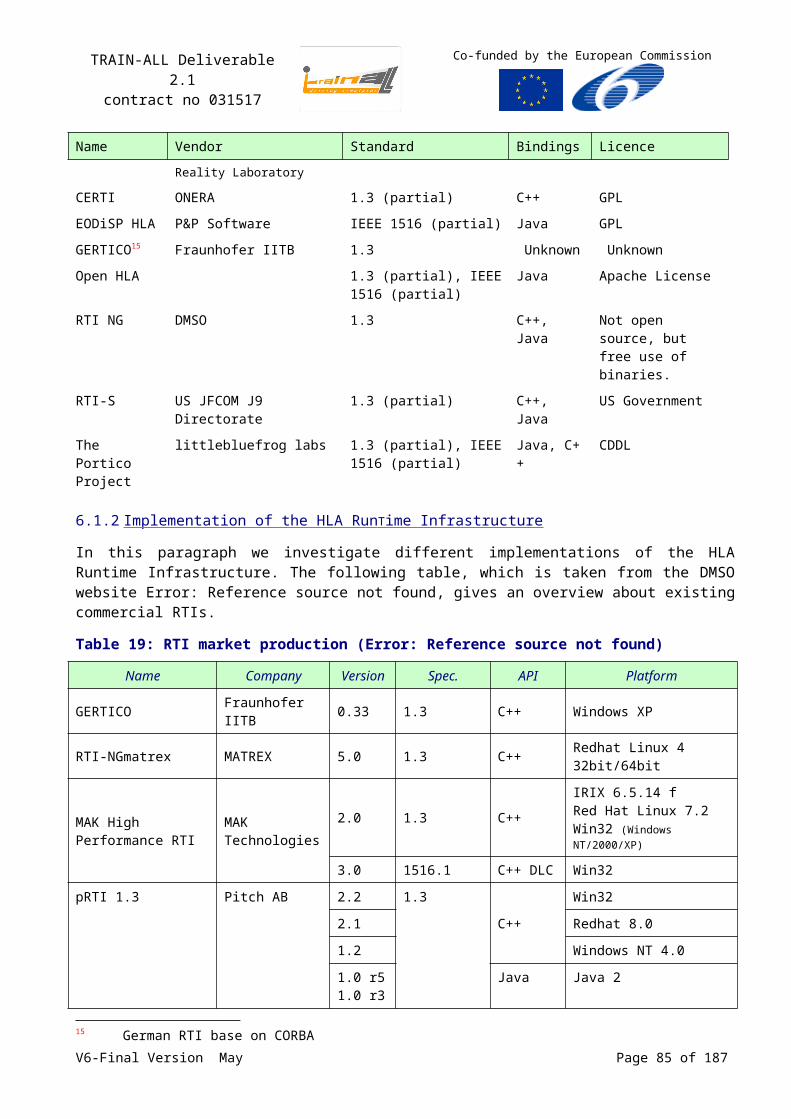
TRAIN-ALL Deliverable 2.1contract no 031517
Co-funded by the European Commission
the SCORM 2004 standard (latest version). The first step was to match the two standards. Both standards define an object reference model and a framework with rules in which their objects are used and distributed. They both have a component-based architecture in which the components connect to a central server (LMS or RTI). This led to a design in which each SCO is treated as a HLA federate. This means that the SCO contains an asset that acts as a HLA federate and has an extension to communicate with the SCORM LMS. In this way each learner/task combination has its own HLA connection to a training simulation. Haynes and Mandikova (2004) use a different approach, where a single HLA federate services all the SCOs. This leads to a relatively complex component that needs to deal with a wide range of training scenarios and simulation data. In the TNO approach a SCO has its own HLA connection and therefore only has to deal with simulation data and training objectives that are specific to that learning task. Another benefit is that it allows multi-user training simulations, since each learner has its own HLA connection to the LMS. Figure 35 shows an overview of the TNO approach.
Figure 35: TNO HLA-SCORM platform, where each SCO has its own HLA and LMS connection
StudentStudent
SCO Repository
SCORM LMS
TNO HLA Run-Time Infrastructure
Intelligent Tutor (System)HLA federate(future work)
SCOSCOSCO
HLA API(Java-HLA federate)
SCORM API(Java-SCORM interface)
HTML/Javascript
3D Visualization(Java applet)
Student Teacher
Training Simulation(HLA federation)
Training Scenario(Java applet)
This overview shows that students and teachers receive a SCO (i.e. a learning task) from the SCORM compliant LMS, which has its own connection with the HLA federation and LMS. Furthermore a simulation specific training scenario is added that uses these connections. This training scenario is the only part that is built specifically for a certain learning task in a specific simulation environment.
V6-Final Version May Page 85 of 140
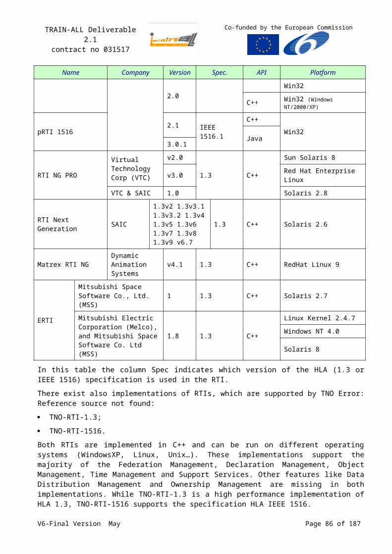
TRAIN-ALL Deliverable 2.1contract no 031517
Co-funded by the European Commission
The SCORM API and the HLA API together with some external tools form the generic part that can be reused in other simulation environments and training scenarios. One of these external tools is a Java code generator that generates Java classes representing the objects described in a Federation Object Model (FOM). These Java classes can be used to build the simulation specific training scenarios and reflect the state of the training simulation and its objects. The tool is part of the TNO Simulation Architecture (TSA) (Huiskamp, 2007) that incorporates its own HLA RTI, libraries and supporting tools. Furthermore, a graphics API has been added to the platform to support 3D visualization (in VRML) of the training simulation.
TNO has built a prototype of the HLA-SCORM platform, called SimSCORM with a 3D visualization. It is currently being evaluated on a driving simulator. The LMS used is an open-source eLearning system: Moodle (www.moodle.org). In the demonstration, the student’s task is to find the teacher’s car as fast as possible by driving in a virtual environment. The demonstration supports multiple students and teachers driving in the same virtual world. Figure 36 shows a student’s SCO in Moodle.
Figure 36: Student SCO in Moodle, presenting a 3D visualization and control of an HLA compliant driving simulator
The vehicles can be controlled via the web interface using keyboard and mouse, but also via an external simulator, like a full scale driving simulator.
Initial evaluation results are promising, but further tests need to be done with more users and scenarios to test network throughput, HLA responsiveness and management of training results. We intend to test the prototype for interoperability and reusability in other simulation environments and training scenarios. Also, development effort of the training tasks proves to minimal, since HLA and SCORM communication is handled by SimSCORM and the developer can focus on the simulation specific training scenario at hand.
SimSCORM is a flexible multi-user platform that can be used to connect to virtually any HLA-compliant training simulation with a SCORM-compliant LMS. It allows development effort to focus on the learning task and simulation environment at hand. External tools are included that facilitate development of new training scenarios.
We are considering several new features, such as:
V6-Final Version May Page 86 of 140
TRAIN-ALL Deliverable 2.1contract no 031517
Co-funded by the European Commission
Decomposition of the evaluation and execution of the learning task, where the evaluation is done by an external HLA federate that may use a virtual instructor based on a complex expert-model. The evaluation result is then transferred via the HLA-RTI to the student SCO, which determines appropriate action and administrates the result.
Feedback from the LMS in external simulators.
Logging and playback of training scenarios via a HLA logger, which logs all HLA communication. This allows a complete review of the entire training scenario.
A generic HLA scenario editor that integrates editing of learning tasks with a SCORM editor. A SCORM editor is used to define SCOs and sequencing rules in a learning course.
Extension of supported HLA and SCORM features.
8.3SimSCORM and TRAIN-ALL
SimSCORM is an integral part of the TNO Simulation Architecture (described in chapter 6.2.1, p.70) and will be able to fulfil many of the TRAIN-ALL objectives as stated before:
SimSCORM provides a loosely coupled framework between HLA federates and SCORM compliant LMSs to the TRAIN-ALL architecture, without any modifications to existing components. This makes it easier to interchange used LMSs and HLA RTIs and introduce new components in the TRAIN-ALL architecture,
SimSCORM enables a strict decoupling of simulation based learning content and the simulator, allowing the learning content to be reusable and sharable.
SimSCORM uses the hierarchal decomposition of learning tasks and objectives of the SCORM data model to support fine-grained and highly adaptive simulation based learning content.
SimSCORM supports automatic real-time assessment using the learning objectives described in the learning content and distribution to external assessment modules (federates).
SimSCORM uses the complete SCORM data model to store individual and team training results on a objective and task level.
SimSCORM uses the HLA network to distribute and share individual progress with other students, simulators and manual or virtual instructors. This enables remote assessment of individual and team training results and a standard interface for simulator based feedback.
TNO participates in the SISO and ADL workgroups to standardize the way simulation based learning content is stored and assessed in the SCORM datamodel and training results are distributed over the HLA network.
V6-Final Version May Page 87 of 140
TRAIN-ALL Deliverable 2.1contract no 031517
Co-funded by the European Commission
9 Conclusions and Recommendations
The proposed solution for the TRAIN-ALL architecture is a generic baseline architecture that allows a range of applications to apply this proposed solution. The main goal of the proposed architecture is its reusability in the domain of driving simulators. The proposed architecture includes the HLA interfaces, the TRAIN-ALL FOM, and the Federation Agreements to make the TRAIN-ALL federates interoperable.
When integrating legacy simulators, it can be helpful to invest in a middleware solution, which shields the development of the modules from the communication services between the modules. Several middleware solutions are proposed in this report.
For the virtual environment and 3D database, it has been decided by the consortium to research into the definition of a road-Network Scenario Format standards. Currently this is not covered by existing open database initiatives like Opendrive.
Furthermore, for interfacing Learning Management Systems and simulators the SCORM standard is proposed.
It is recommended to use the baseline architecture as a guideline for the experiments. The architecture has to be detailed or fine-tuned according to the needs of the experiments. Common needs that are identified during the experiments can then be captured in the proposed architecture.
V6-Final Version May Page 88 of 140
TRAIN-ALL Deliverable 2.1contract no 031517
Co-funded by the European Commission
10Reference and bibliography
These documents constitute the reference for the management of the project. There are the applicable documents issued before the launch of the project and the different plans produced by the TRAIN-ALL project itself. The Quality manager ensures that the quality plan is available to all concerned regarding this Baseline and that its requirements are met.
10.1 TRAIN-ALL documents production
Table 22: TRAIN-ALL documents productionTitle Deliverable Dissemination Level
Project Management and Quality Manual [D8.1] Project Quality Manual
Public
Annex I - “Description of Work”, TRAIN-ALL project, 23, Feb.-06CN. 031517, Sixth Framework Programme.
[DoW] TRAIN-ALL Project Proposal
Restricted
Benchmarking and classification of CBT tools for driver training.
[D1.1] Public
Training Needs, Scenario and Curricula Definition and Specification of Tools and Curricula
[D1.2] Restricted
Verification Pilot Plans and Ethics Manual [D5.1] Public
10.2 Referenced Documents
Table 23: Referenced DocumentsReference Title Date Comment
[TRAIN-ALL-FOM] TRAIN-ALL FOM file
[DIS 1995] IEEE Standard for Distributed Interactive Simulation-Application Protocols, 1278.1-1995,
26 March 1996
IEEE Std 1278.1-1995
[DIS 1998] IEEE Standard for Distributed Interactive Simulation-Application Protocols, 1278.1A-1998
1998 IEEE Std 1278.1A-1998
[HLA]IEEE 1516-2000 Standard for Modelling and Simulation (M&S) High Level Architecture (HLA) - Framework and Rules
September 2000
[OMT]IEEE 1516.2-2000 Standard for Modelling and Simulation (M&S) High Level Architecture (HLA) - Object Model Template (OMT) Specification
September 2000
[FEDEP]IEEE 1516.3-2003 Recommended Practice for High Level Architecture (HLA) Federation Development and Execution Process (FEDEP)
April 2003
V6-Final Version May Page 89 of 140
TRAIN-ALL Deliverable 2.1contract no 031517
Co-funded by the European Commission
Reference Title Date Comment
[RPR-FOM] Real-time Platform Reference Federation Object Model (RPR FOM) - Version 2, Draft 17
October 2003
[GRIM]Guidance, Rationale, and Interoperability Manual for the Real-time Platform Reference Federation Object Model (RPR FOM) - Version 2, Draft 17
October 2003
[TNO-RCI] RCI Reference Guide, TNO-RCI Version 5.2, TNO Defence, Safety and Security
July 2007
[OPENDRIVE]Format Specification, Rev. 1.2VIRES Simulationstechnologie GmBH,
2nd, Januray
2008
Public on www.opendrive.org
[OKTAL-RND] [RND] Road Network Description, Dossier de specifications du format RND V1.2
27 April 2006
[2TRAIN] Catalogue of standards for training technology D1.1.1 2TRAIN project 031424 STREP
Feb.-07
[FEDEP] DMSO, HLA Federation Development and Execution Process (FEDEP) Model, version 1.4
1 July1999
[RTIS] http://dss.ll.mit.edu/dss.web/stow.html
[GMU] http://netlab.gmu.edu/rti/
[YaRTI] http://perso.orange.fr/dominique.canazzi/dominique.htm
[JaRTI] http://wiki.littlebluefroglabs.com/index.php?title=JaRTI
[XRTI] http://sourceforge.net/projects/npsnetv/
[OHLA] http://sourceforge.net/projects/ohla/
[OMDT] http://www.aegistg.com/AEgisTechnologiesProducts_LabWorks2.html
[SIMp] http://www.calytrix.com/siteContent/SIMplicity/intro.php
[Mdat] http://www.mak.com/products/datalogger.php
[vrl] http://www.mak.com/products/vrlink.php
[Certi] http://www.nongnu.org/certi/
[pdev] http://www.pitch.se/products/pitch-developer-studio/pitch-developer-studio.html
[pvis] http://www.pitch.se/products/visual-omt/visualize-and-collaborate.html
[EOD] http://www.pnp-software.com/eodisp/
[DRTI] https://www.dmso.mil/public/transition/hla/rti
[DStat] https://www.dmso.mil/public/transition/hla/rti/statusboard
[TSA] TNO Simulation Architecture (TSA), TSA Product Description
July 2006
HLA Home Page http://hla.dmso.mil
V6-Final Version May Page 90 of 140
TRAIN-ALL Deliverable 2.1contract no 031517
Co-funded by the European Commission
Reference Title Date Comment
Hunt, K. Dahmann, J., Lutz, R., and Sheehan, J., Planning for the Evolution of Automated Tools in HLA (97S-SIW-067), Spring Simulation Interoperability Workshop
1997
SIW - 1998 Fall Simulation Interoperability Workshop (98F-SIW-101), (98F-SIW-123)
SIW - 1998 Spring Simulation Interoperability Workshop (98S-SIW-043, 98S-SIW-100, 98S-SIW-142)
Fullford, D., Wetzel, D., A Federation Management Tool: Using the Management Object Model to Manage, Monitor, and Control an HLA Federation
V6-Final Version May Page 91 of 140
TRAIN-ALL Deliverable 2.1contract no 031517
Co-funded by the European Commission
Annex A High Level Architecture (HLA) Standard
A1 Concepts of the High Level Architecture
The High Level Architecture (HLA) is a standard framework that supports simulations composed of different simulation applications. In the terminology of HLA, an individual simulation application is known as a Federate. Federates may be simulation models, data collectors, simulators, Computer Generated Entities or passive viewers. The collection of Federates brought together to form a synthetic environment is known as a Federation.
All possible data exchanged by Federates in a Federation is captured in an object model. The Object Model Template (OMT) provides a format for this object model. The object model may contain ‘HLA objects’ to describe the persistent state of entities, and ‘HLA interactions’ to describe transient events. An individual Federate is described by its Simulator Object Model (SOM). The SOM is an object model in the OMT format that provides details of the object attributes and interactions that this Federate either provides or receives information about. All data that is potentially exchanged in a collection of Federates (i.e., the Federation) is described by the Federation Object Model (FOM). The FOM is also an object model in the OMT format that contains all objects and interactions that the Federates may exchange. Since all information is available in the individual SOM’s, the FOM can be constructed out of the SOMs.
Data exchange between Federates is processed through the underlying communication layer, called the Run Time Infrastructure (RTI). Federates may give advise, or send requests to the RTI, and the RTI can respond asynchronously by invoking certain well-known call-back methods. A callback is a user-defined piece of software code (with a given interface) that is invoked by the RTI when a certain event occurs.
HLA has a set of ten basic ‘rules’ that federates must comply to:
Table 24: the 10 HLA-RulesFederation Rules Federate Rules
Federations shall have a FOM, documented in accordance with the OMT.
Federates shall have a SOM, documented in accordance with the OMT.
All representation of objects in the FOM shall be in the federates, not in the RTI.
Federates shall be able to update and/or reflect any attributes of objects in their SOM, and send and/or receive SOM interactions externally, as specified in their SOM.
During a federation execution, all exchange of FOM data among federates shall occur via the RTI.
Federates shall be able to transfer and/or accept ownership of attributes dynamically during a federation execution, as specified in their SOM.
During a federation execution, federates shall interact with the RTI in accordance with the HLA interface specification.
Federates shall be able to vary the conditions under which they provide updates of attributes of objects, as specified in their SOM.
During a federation execution, an attribute of an instance of an object shall be owned by only one federate at any given time.
Federates shall be able to manage local time in a way which will allow them to coordinate data exchange with other members of a federation.
V6-Final Version May Page 92 of 140
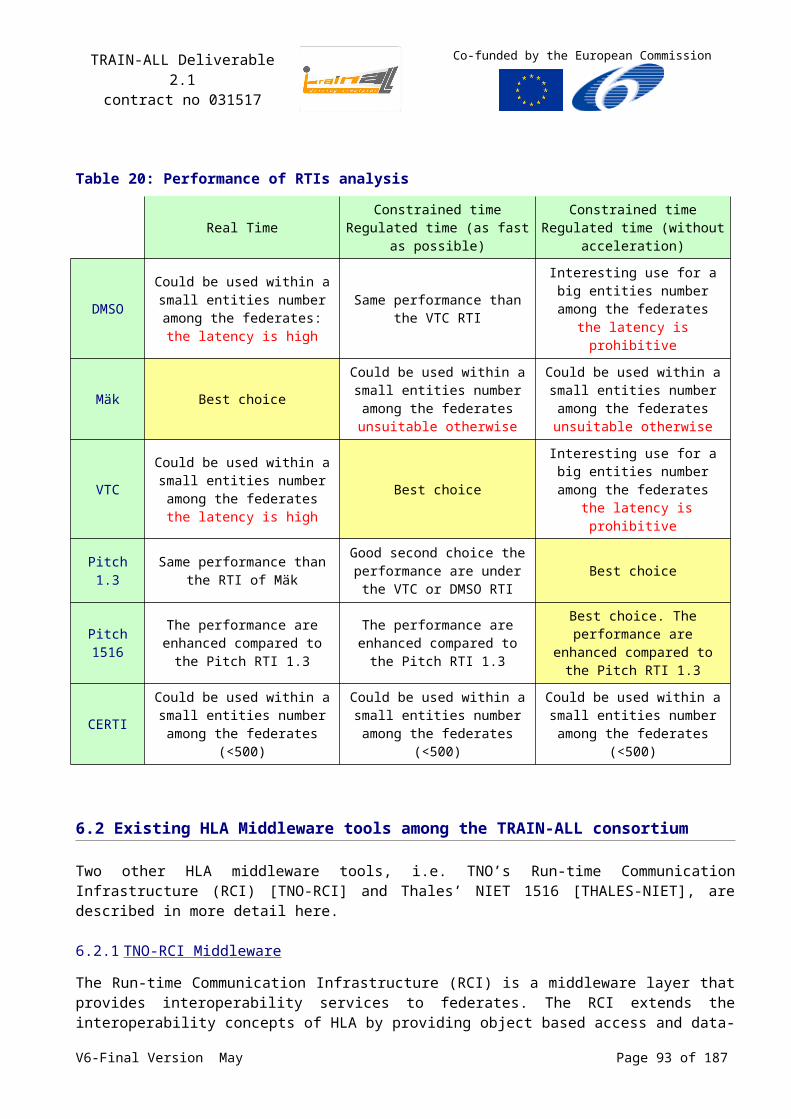
TRAIN-ALL Deliverable 2.1contract no 031517
Co-funded by the European Commission
A2 The RTI services
The complete overview of (HLA/RTI) service groups is listed below.
1. Federation ManagementThis set provides the means to create and destroy federation executions, pause and resume federation executions, save and restore the federation state, and it provides a barrier synchronization mechanism.
2. Declaration ManagementThis set provides the means by which the federates express their interest in receiving data of specific object class attributes (which they have subscribed to). Federates that own object attributes can update their attribute values and have to publish those object class attributes.
3. Object ManagementThis set provides the means by which federates update and receive new values for object attributes and interactions. Federates also use this set to create, register, and destroy locally owned HLA objects, and discover HLA objects owned by other federates, i.e., remotely owned objects. In addition, the federate can instruct the RTI to use certain transportation and ordering mechanisms for the transfer of data.
4. Ownership ManagementThis set provides the means by which the ownership of individual object instance attributes can be transferred between federates. A federate that owns a certain object instance attribute can provide new values for it. This service set allows the distribution of a single HLA object amongst a number of federates.
5. Time ManagementThe set provides the means federates advance their simulation time and co-ordinate their time advances. Different time management schemes are allowed, in particular event-driven and time-stepped simulations that can be coordinated to preserve causality in the order in which time-stamped messages are delivered.
A time-constrained federate is a joined federate that may receive time stamp order messages and whose time advances are constrained by other joined federates within a federation execution.
A time-regulating federate is a joined federate that may send time stamp order messages and that constrains the time advances of other joined federates within a federation execution.
6. Data Distribution ManagementThis set provides the means to more efficiently route data between the federates based on the actual value of an attribute instead of the type of the attribute. In this way, it extends the declaration management service set and its publish-subscribe mechanism.
A3 The FEDEP Methodology
The model for the high-level process by which (HLA) Federations should be developed and executed to meet the sponsor's requirements is known as the Federation Development and Execution Process (FEDEP) Model. The FEDEP is based on well known systems engineering principles, but was tailored to meet the needs of a distributed simulation system that is designed according to the HLA approach.
The FEDEP is a seven-step process.
V6-Final Version May Page 93 of 140
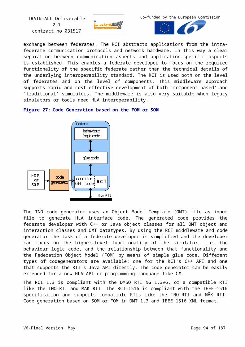
TRAIN-ALL Deliverable 2.1contract no 031517
Co-funded by the European Commission
Figure 37: Top-level view of the FEDEP
The seven basic FEDEP steps are described below.
1. Define federation objectivesDefine and document a set of needs that are to be addressed through the development and execution of an HLA federation, and transform these needs into a more detailed list of specific federation objectives.
2. Perform conceptual analysisDevelop an appropriate representation of the real word domain that applies to the federation problem space and develop the federation scenario. Transform the federation objectives into a set of highly specific federation requirements that will be used in the federation design, development, execution and evaluation. From the perspective of Object-Oriented (OO) software designers, the federation conceptual model can be compared to elements of an object model. That is, the focus of federation conceptual model development is to identify federation objects, to identify static and dynamic relationships between object classes, and to identify the behavioural and algorithmic aspects of each class/object.
3. Design FederationThe purpose of this step is to produce the design of the federation that will be implemented in step 4. This involves identifying existing federation participants (federates) that are suitable for re-use, creating new federates and federate components if required, allocating the required functionality to federates, and developing a detailed plan for federation development and implementation.
4. Develop FederationThe purpose of this step is to develop the Federation Object Model (FOM), modify federates if necessary, and prepare the federation for integration and test (database development, security procedure implementation, etc.).
5. Integrate and Test FederationThe purpose of this step is to plan the federation execution, establish all required interconnectivity between federates, and test the federation prior to execution.
6. Execute Federation and Prepare ResultsThe purpose of this step is to execute the federation and to pre-process the output data from the federation execution.
7. Analyse data and evaluate resultsThe purpose of this step is to analyse and evaluate the data acquired during the federation execution (Step 6), and to report the results back to the user/sponsor. This evaluation is necessary to ensure that the federation fully satisfies the requirements of the user/sponsor. The results are fed back to the user/sponsor so that they can decide if the federation objectives have
V6-Final Version May Page 94 of 140
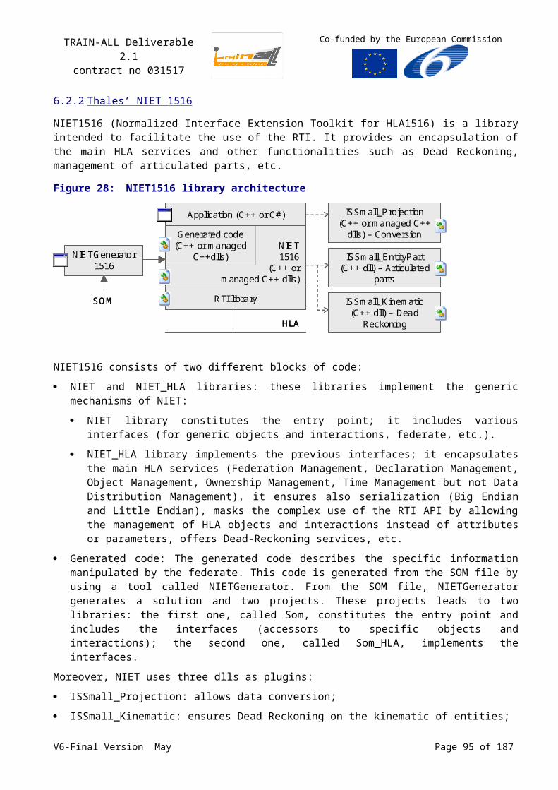
TRAIN-ALL Deliverable 2.1contract no 031517
Co-funded by the European Commission
been met, or if further work is required. In the latter case, it will be necessary to repeat some of the FEDEP steps again with modifications to the appropriate federation products.
Figure 38: Detailed view of the FEDEP
V6-Final Version May Page 95 of 140
TRAIN-ALL Deliverable 2.1contract no 031517
Co-funded by the European Commission
Annex B Distributed Interoperable Simulation (DIS) Standard
B1: Some history
The first well established interoperability standard that appeared was the Distributed Interactive Simulation (DIS) protocol. DIS is an IEEE standard for real-time simulation systems to exchange information using Protocol Data Unit (PDU) formats to send several types of simulation information.
PDUs are the generic name for the various simulation data record formats used by the DIS protocol. PDU record formats include the Entity state PDU, Fire PDU, Detonate PDU, IFF PDU, Send PDU, Simulation Start PDU, etc. (See http://www.pitch.se/fmv/dis-items/Pduindex.htm).
DIS is widely used and many simulation systems support the standard. However, many applications have added extensions to the PDUs to allow for specific information that was not covered by the DIS standard. This resulted in user defined PDUs hampering interoperability and involving extensive integration efforts when new federations are being developed. Proprietary additions are not likely to become part of the DIS standard since development of the standard has been halted in favour of the High Level Architecture standard (HLA).
The Defence Modelling and Simulation Office (DMSO) is the lead for modelling and simulation (M&S) activities within the U.S. Department of Defence. This organisation is charged with maximising the efficiency and effectiveness of M&S efforts across the DoD and fostering interoperability and reuse of models and simulations. DMSO projects include the development and promotion of HLA (Web Site: http://www.dmso.mil/).
B2: Evolution of the RPR-FOM
Version 1.0 of the RPR-FOM provided an HLA conversion path for the DIS capabilities defined in [DIS 1995]. Version 2.0 of the RPR-FOM adds the functionality of the IEEE 1278.1a-1998 defined in [DIS 1998]. Draft 17 (3rd October 2003) is the last released draft of the RPR FOM version 2.0 (See Error:Reference source not found), which is used for the current standardisation of the RPR FOM. This is the version used for TRAIN-ALL-FOM.
V6-Final Version May Page 96 of 140
TRAIN-ALL Deliverable 2.1contract no 031517
Co-funded by the European Commission
Annex C Example Template for Federate Information Exchange
The A2.1 team requested the developers of TRAIN-ALL modules to provide an overview of the information exchange needs and capabilities of each module. This information is used as a guideline to develop the TRAIN-ALL FOM. The example below shows the questionnaire as returned by TNO for its manned driving simulator.
C1 General Information
Application Name Research
Short Description Driving Simulators for Research
Point of Contact W. Hoekstra
Comments
C2 Initial Data
Please provide the ‘initial data’ that your application needs and that may also be required in some way by other applications that your component will interface with. For example: road-network description (both for visual as well as for logical representation on type of road etc). Note that this data is usually not exchanged during ‘runtime’, but rather read from a file before the exercise or simulation is started.
Initial Data can also be supplied from a visual DataBase (or a CGE) server. (It can be also issued from scenario or vehicle model or natural environment).
Please provide a description / documentation of the type of data and the representation format that is needed. Please add a table for each type of data.
Type of data Road Network Description
Representation or formats (e.g. OpenFlight, XML etc)
Text
Comments This road network description is needed if you want to extract performance parameters where road interaction is crucial. (Like time to line crossing, time to contact etc.)
Type of data Visual DataBase
Representation or formats (e.g. OpenFlight, XML etc)
OpenFlight or OSG23
Comments If you want to extract performance parameters where no road interaction is needed, questionnaires, response times …..
23 Open Scene Graph format V6-Final Version May Page 97 of 140

TRAIN-ALL Deliverable 2.1contract no 031517
Co-funded by the European Commission
C3 Runtime Data Input
Please provide the ‘runtime data’ that your application needs from a specific other component or application that your component will interface with. For example: position information of the vehicle that is provided as a manned driving simulator. Please add a similar table for each separate component that you expect to interface with and for each type of data that is needed.
Name/Type of Other component (datasource)
External Vehicles
Type of data received (e.g. position data)
Position & velocity data + Roadnetwork data
Representation or formats (e.g. x,y,z in Cartesian coordinates etc)
x, y, z, dx, dy, dz, heading, pitch, roll lane-identifier + CarState
Required accuracy cm
Required update rate 60 Hz
Comments External Vehicles are either other simulators or vehicles from a macro/microscopic traffic model
Name/Type of Other component (datasource)
Road State
Type of data received (e.g. position data)
Id + State
Representation or formats (e.g. x,y,z in Cartesian coordinates etc)
On/Off Text
Required accuracy
Required update rate 60 Hz
Comments State of traffic light. Text on DRIPS, VMS, GRIPS etc.
C4 Runtime Data Output
Please provide the ‘runtime data’ that your application will provide to specific other components or applications that your component will interface with. For example: position information of the vehicle(s) that your application simulates. Please add a similar table for each separate component/application that you expect to interface with and for each type of data that is provided.
Name/Type of Other component (i.e. data destination)
Note: the data may not be directed at a specific destination, but provided for general use)
Macroscopic traffic model
Type of data provided (e.g. position data)
Position data
V6-Final Version May Page 98 of 140
TRAIN-ALL Deliverable 2.1contract no 031517
Co-funded by the European Commission
Representation or formats (e.g. x,y,z in Cartesian coordinates etc)
x, y, z, HPR
Provided accuracy mm
Provided update rate 60 Hz
Comments Any other vehicle specific value can be on the output line
C5 Evaluation Data
Please provide the ‘evaluation data’ that your application may supply in some way after completion of the simulation or application run. For example: student assessment data. Note that this data is usually not exchanged during ‘runtime’, but rather collected during runtime and readback from file after the exercise or simulation. Please add a table for each type of data.
Type of data (e.g. student performance)
none
Representation or formats (e.g. XML etc)
Comments
C6 Interaction Exchange
What are the events between your module/ demonstrator as a federate and the other federates (e.g. simulation start/ stop/ freeze, scenario loading control, error… vehicle event as braking, overtaking, collision, etc..
Name/Type of event
Type of data describing the event
Representation or formats
Comments
V6-Final Version May Page 99 of 140
TRAIN-ALL Deliverable 2.1contract no 031517
Co-funded by the European Commission
Annex DThe TRAIN-ALL modules functional description1. Ambient intelligence in driving simulation (ambient
intelligence or AI in the text),
This innovative module will monitor actual drivers profile in a driver simulator (in particular scenarios) in order to build a driver behaviour model and offer natural simulation environments and the enabling of training personalisation according to each driver’s own driving style.
It will be used to represent the “natural” surrounding traffic to the trainee.
2. Co-driving, cooperative and group training (co-driving in text),
This module will enable solutions, training and evaluation methods for the co-driving training between the pilot and the co-pilot from a set of Police mission scenarios, which cover different themes as knowing where you drive, accidents and causes of damage, responsibility and tactics in emergency driving. New methods of team training will be proposed and then validated.
3. Immersive simulation for multi-vehicle (immersive simulation in the text),
This module will allow, by means of Virtual Reality technologies, to switch quickly from a given vehicle type to another, and even from a given vehicle category to another, this in order to train the novice driver with a gradual approach, starting from easy-to-drive vehicles till to “difficult” ones.
The 3D visualization will allow a good perception of sizes and distances, and the head tracking will allow a right visual interaction among driver, interiors and external scenario.
This module will be made up mainly by a mechanical reconfigurable mockup, a virtual mockup toolbox for a rapid creation of cab interiors, a rear view mirrors sw module.
4. P2P Internet technologies for CBT (P2P in the text),
This module will set up an Internet remote control and its instructor functionalities to the TRAIN-ALL demonstrators The Remote control tool is a software tool, which can be run on an arbitrary computer in the internet to control remote a simulator;
This includes connection to any IP-known simulator, scenario selection, passing commands to the simulator, choosing alternatives, showing simulation variables and system information of the simulator, showing a video stream of the trainee and different views on the scenario
5. Virtual instructor and debriefing (virtual instructor in the text),
This module will measure “objectively” the driver’s performance and behaviour in regard to a representative set of normative values and give assistance to assessment or self-assessment by a simple automatic protocol during the exercise or the debriefing
The immediate results of assessment could be used to manage the exercise sequence itself
6. Dynamic scenario management,
This module will manage the scenarios as a set of short sequence with certain traffic, terrain and rendered difficulties.
It will build an adapted trainee exercise sequence from the curricula objective or for example from the feedback of the automatic assessment from the VI.
It will reduce the work cost of the scenarios script realisation and enhance the capacity to profile the exercise to the trainee benefit.
7. ADAS/ IVICS simulation,
This module will consist of a set of scenarios to simulate the functionalities of ADAS and IVICS.
The aim is to train drivers on ADAS/ IVICS functionalities, their potential benefits, as well as limitations under various relevant traffic environments and scenarios.
8. Simulator sickness,
This module will produce an analysis of the road driving simulator sickness and recommendation to detect it and to minimize or avoid it in exercise operation or by design
9. Enhanced reality,
This module will produce dynamic highlighted data into the visual display of the synthetic environment in the simulator. This highlight will permit to put on the scene relevant parameters in the dynamic situation for the perception benefit of the trainee
10. Adaptive training.
This module will offer a capacity to build appropriate training session to the trainee
The Adaptative capacity will be built through an ascending order of difficulties, with additional sequence training where trainee errors have been detected
And so the scenario sequences would be daisy chained to realize the exercise as they are compatible and linkable among them
The bind decision will be made from the task assessment
V6-Final Version May Page 100 of 140
TRAIN-ALL Deliverable 2.1contract no 031517
Co-funded by the European Commission
Annex E The TRAIN-ALL demonstrators to be integrated
Demonstrators
Modules M
otor
cycl
e (IN
RE
TS)
Truc
k (T
HA
LES
)
Em
erge
ncy
(WIV
W &
BP
P)
Em
erge
ncy,
(W
IVW
)
Pas
seng
er
(WIV
W)
Pas
seng
er
(FO
ER
ST)
Imm
ersi
ve (C
RF)
Mul
tipur
pose
(G
RE
EN
DIN
O)
A4.
1
A4.
2
A4.
3
A4.
4
A4.
5
A4.
6
Wished
A3.1 Ambient intelligence √ √ √ √
A3.2 Co-driving √ √
A3.3 Immersive √
A3.4 P2P Internet √ √ √ √
A3.5 Virtual instructor √ √ √ √ √
A3.6 Dynamic scenario √ √ √ √
A3.7 ADAS/ IVICS √ √ √ √ √
A3.8 Sickness √ √ √ √ √ √ √
A3.9 Enhanced reality √ √
A3.10 Adaptive training √ √
Interface Proposition
A3.1 Ambient intelligence P P P
A3.4 P2P Internet ? HLA HLA
A3.5 Virtual instructor
(GD)HLA
P
(INRETS) P
(FOERST) P
(WIVW) P
A3.6 Dynamic scenario HLA P
A3.7 ADAS/ IVICS P/HLA? HLA? P P/HLA?
A3.9 Enhanced reality P P
A3.10 Adaptive training P P
Clarification: HLA = HLA interface, P = Proprietary interface, P/HLA = Proprietary and/or HLA, not decided yet.
V6-Final Version May Page 101 of 140
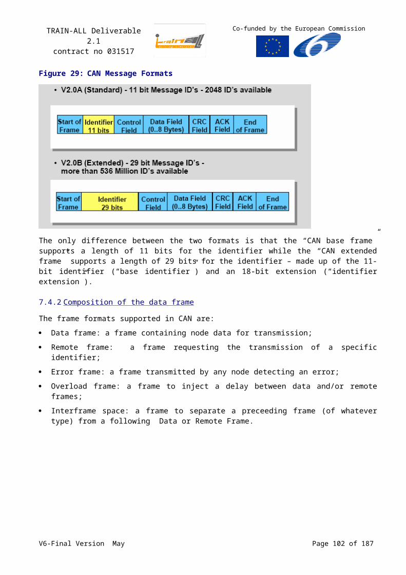
TRAIN-ALL Deliverable 2.1contract no 031517
Co-funded by the European Commission
From the simulators as presented in the top row and the interfaces to the different modules, the various demonstrators will be defined. This Table shows the type of interfaces the different mapping of all the proposed TRAIN-ALL modules and simulators as listed in Section 2.4 onto the HLA federates in the TRAIN-ALL prototype federation.
As can be seen from the table, the HLA principle will be demonstrated by at least three demonstrators. The decisions for not having all interfaces between the TRAIN-ALL modules and the simulators on the HLA standard are based on the following:
Competitiveness: The driving simulator domain consists of many manufacturers within Europe. The products of these manufacturers distinguish by themselves the implementation and functionality of the simulator and their modules. In fact, the HLA standard is designed for interoperability between simulators and for TRAIN-ALL this interoperability was proposed to be extended to the simulator component/module level, because interoperability between simulator components/modules seemed to be beneficial for a future European policy on building driving simulators. However, currently the competitive edge within Europe is prevailing above a still non-existing future European policy.
Complexity: Some participants with no knowledge on the HLA standard regard the integration and adaptation of modules and simulators to the HLA standard too complex for the intended purpose, in spite of the fact that middleware solutions provide easy integation.
Cost: The cost for adapting the simulators and TRAIN-ALL module interfaces is regarded as too high for the project. Also licence costs for future applications are regarded as too high, compared to list prices of driving simulators.
V6-Final Version May Page 102 of 140
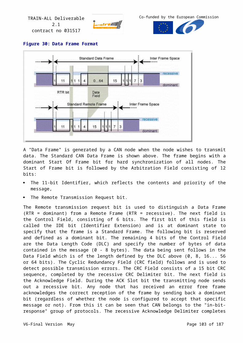
TRAIN-ALL Deliverable 2.1contract no 031517
Co-funded by the European Commission
Annex F Federate identification number
The 15 different exploitable products are expected to emanate from the project, namely (see Error:Reference source not found): D3.1 Ambient Intelligence module (s/w) D3.2 Co-driving, cooperative and group
training module (s/w) D3.3 Immersive simulation Platform (s/w) D3.4 P2P tool (s/w) D3.5 Virtual Instructor and debriefing
module (s/w) D3.6 Dynamic scenario management
module (s/w) D3.7 ADAS/IVICS simulation module (s/w) D3.10 Enhanced reality module (s/w)
D3.11 Module for controlling adaptive training sequences (s/w)
D4.1 Adapted motorcycle simulator (s/w) D4.2 Adapted truck simulator (h/w and s/w) D4.3 Adapted car simulator prototype for
emergency vehicle drivers (h/w and s/w) D4.4 Adapted car simulator for novice
drivers (h/w and s/w) D4.5 Adapted VR simulator (h/w and s/w) D4.6 Multi-purpose driving simulator (h/w
and s/w)
No. Participant name Short name
1 Centre for Research and Technology Hellas / Hellenic Institute of Transport CERTH/HIT
2 Transport Research Laboratory TRL
3 University of Stuttgart USTUTT
4 Institute of Communications and Computer Systems ICCS
5 Nederlandse organisatie voor Toegepast Natuurwetenschappelijk Onderzoek TNO
6 Center for Traffic Sciences at the University of Wuerzburg IZVW
7 Reiner Foerst GmbH FOERST
8 Green Dino Virtual Realities BV GREEN DINO
9 Thales Training & Simulation THALES
10 Institute for Occupational Physiology at the University of Dortmund IFADO
11 Centro Ricerche FIAT S.c.p.a. CRF
12 Präsidium der Bayerischen Bereitschaftspolizei – Bavarian police BPP
13University of Basel, Department of Psychiatry, Center of Applied Technologies in Neuroscience COAT
14 Non assigned -
15 Swedish National Road and Transport Research Institute VTI
16 Universität Passau UP
17 Wuerzburger Institut für Verkehrswissenschaften WIVW
18 Institut National de REcherche sur les Transports et leur Sécurité INRETS
V6-Final Version May Page 103 of 140

TRAIN-ALL Deliverable 2.1contract no 031517
Co-funded by the European Commission
Annex G TNO Simulation Architecture Description
Figure 39: TNO Simulation Architecture (TSA) supporting HLA applications
Federate
DIS / HLA-RTI / ...
Run-time Communication Infrastructure (RCI)
Federate Federate
DIS / HLA-RTI / ...RCI
ComponentComponent FederateManager
TSA Product Description - February 2008
TNO Defence, Security and Safety
PO Box 96864
2509 JG The Hague
The Netherlands
POC: Wim Huiskamp
Email: [email protected]
Tel +31 (0)70 3740274
G1 Products Overview
The TNO Simulation Architecture (TSA) is a simulation tool suite that extends the High Level Architecture (HLA) interoperability standard down to the level of components.
The TSA tool suite provides:
Support for Re-Use of HLA based simulation Components,
Seamless integration of legacy simulators and simulation components into an HLA environment (including COTS/GOTS),
Support for reconfigurability through the exchange of simulation Components,
Support for integration of Virtual and Constructive simulations in a shared synthetic environment,
Support by a federation development process and accompanying tools.
G2 TNO Simulation Architecture (TSA)
The TSA architectural concept extends HLA to the simulation Component level: an individual HLA Federate is itself composed of various functional components that interact through the same architecture and underlying middleware as the overall HLA Federation.
Consequently, a simulator can be thought of as a set of interacting components; the total functionality of the simulator may be expressed as the ‘sum’of the functionality of its constituting components.
The TSA interoperability middleware layer (Run-time Communication Infrastructure or RCI) is used both on the level of Federates and on the level of Components. This middleware approach supports rapid and cost-effective development of both ‘component based’ and ‘traditional’ simulators. The
V6-Final Version May Page 104 of 140
TRAIN-ALL Deliverable 2.1contract no 031517
Co-funded by the European Commission
middleware is also very suitable when an interoperability layer is required for existing simulations or tools.
G3 TSA Framework
The TSA Framework (see Figure 39) is an implementation of the TSA architectural concept. It supports the customer when developing component based synthetic environments. The TSA Framework consists of the TSA Infrastructure products and the TSA Support Tools.
There are two TSA Infrastructure software products:
TSA-RCI Run-time Communications Infrastructure
TSA-FMC Federate Manager Component
Currently there are three types of TSA Support Tool products available:
TNO-RTI (HLA 1.3 and IEEE1516)
TSA Codegenerators (RCI and Java)
TSA Gateways (DIS/HLA)
G4 Run-time Communication Infrastructure (TSA-RCI)
The Run-time Communication Infrastructure is the TSA interoperability middleware layer that provides all interoperability services to both the Components and Federates. Each set of Components or Federates interacts with the synthetic environment through this set of services. The innovative approach of TSA is that the RCI extends the Federate interoperability concepts of HLA by providing data-exchange between Components in a similar way. The RCI abstracts Components from the intra-Federate communication protocols and network hardware. In this way a clear separation between communication aspects and application-specific aspects is established. This enables a Component developer to focus on the required functionality of the specific Component rather than the technical details of the communication aspects.
Figure 40: Runtime Communication InfrastructureFunctional part
data transport
component / federatecomponent / federate
DISDIScomm. servercomm. server
HLAHLAcomm. servercomm. server
{{RCIRCI
High SpeedHigh Speedcomm. servercomm. server
environmentInterface layer
communication servercommunication server
RCI interfacedata access
The RCI consists of two separate software layers, one is called the Interface layer and the other is called the Communication Server. The Interface layer provides data-access to the data that is available in the synthetic environment. This layer shields the application (component or federate) from the underlying interoperability standard.
The Communication Server provides data transport from and to the synthetic environment.
Dedicated versions of the Communication Server can be implemented for the support of specific simulation protocols or network layers. This requires no changes in the application-specific source
V6-Final Version May Page 105 of 140

TRAIN-ALL Deliverable 2.1contract no 031517
Co-funded by the European Commission
code as it merely interacts with the Interface layer. The Communication Server is based on the HLA RTI (both NG 1.3 and IEEE 1516), but allows other standards such as DIS.
The RCI is supported by a C++ code-generator that translates the Component's or Federate's capabilities (specified in HLA-OMT format) into easily accessible object-oriented classes.
The code generator hides complexities of the underlying interoperability standards and enables simulation protocol migration with minimal changes to the functional implementation of the Component or Federate.
Features RCI-1.3: The RCI is compliant with the DMSO RTI NG 1.3v6, or a compatible RTI like the TNO-RTI when
high performance is required,
HLA support of Federation Management, Declaration Management, Object Management, Time Management, and Data Distribution Management,
Real-time Scheduling support (with TNO-RTIs),
Rapid and thus cost-effective development support through its easy to learn API and seamless integration with the RCI C++ Code Generator during federation development,
C++ code generation for RCI based on SOM or FOM in OMT 1.3 format,
Support of several data marshalling schemes, e.g. XDR, for network traffic,
Straightforward installation,
Software User Manual with worked examples.
Features RCI-1516: The RCI-1516 is compliant with the RTI IEEE-1516 specification and supports compatible RTIs
like TNOs RTI-1516,
HLA support of Federation Management, Declaration Management, Object Management, Time Management, and Data Distribution Management,
Real-time Scheduling support (with TNO-RTIs),
Rapid and thus cost-effective development support through its easy to learn API and seamless integration with the RCI C++ Code Generator during federation development,
C++ code generation for RCI based on SOM or FOM in XML 1516 OMT format
Support of IEEE Std 1516.2-2000 data marshalling scheme for network traffic,
Support for a mixed mode federation of RCI-1.3 and RCI-1516 federates, when using the TNO-RTIs.
Straightforward installation,
Software User Manual with worked examples.
Table 25: RCI Computer Platforms/CompilersProduct Supported Computer Platforms / Compilers
Run-time Communication Infrastructure TNO-RCI-1.3
Windows 2000/XP, MSVC++ 6.0 compiler
Windows 2000/XP, MSVC++ 7.1 compiler (.NET 2003)
Windows 2000/XP, MSVC++ 8.0 compiler (.NET 2005)
Linux 2.6 Kernel, RedHat Enterprise Linux 4.2, gcc 3.4.6 compiler
Irix 6.5 n32 mips3, MIPSpro 7.3.1.3m compiler
V6-Final Version May Page 106 of 140
TRAIN-ALL Deliverable 2.1contract no 031517
Co-funded by the European Commission
Product Supported Computer Platforms / Compilers
SunOS 5.9, SPRO 5.3 compiler
Run-time Communication Infrastructure TNO-RCI-1516
Windows 2000/XP, MSVC++ 6.0 compiler
Windows 2000/XP, MSVC++ 7.1 compiler (.NET 2003)
Windows 2000/XP, MSVC++ 8.0 compiler (.NET 2005)
Linux 2.6 Kernel, RedHat Enterprise Linux 4.2, gcc 3.4.6 compiler
Irix 6.5 n32 mips3, MIPSpro 7.3.1.3m compiler
SunOS 5.9, SPRO 5.3 compiler
Federate Manager Component (TSA-FMC)The TSA architectural concept identifies a special component, called Federate Manager Component (FMC). The FMC role is to represent a specific set of Components as a single Federate to the Federation, thereby shielding the internal component structure and data exchange from the other Federates. Furthermore, the FMC manages all simulation execution state changes at the component level (e.g. start simulation, pause simulation, stop simulation).
To allow a federate to be (re-)used in different federations its SOM must be compliant with the FOM of the federation. For this reason the capabilities of the Federate Manager Component (FMC) are extended so that its SOM can be translated into the given FOM in a straightforward way. This feature, known as 'FOM agility', translates the user defined mapping from SOM to FOM.
Figure 41: Federate Manager Component (GUI)
Features FMC Version 1.1:
The FMC is build on top of the TNO-RCI middleware layer,
C++ code generation for specific SOM and FOM source code,
FOM agility, automatic as well as manual SOM to FOM mapping,
FMC implements and synchronises a user defined execution state transition diagram,
Monitors the simulation execution states of all Components,
Straightforward installation,
Software User Manual with worked examples.
Table 26: TSA Federate Manager Computer Platforms/CompilersProduct Supported Computer Platforms / Compilers
TSA Federate Manager Irix 6.5 n32 mips3, MIPSpro 7.3.1.3m compiler
V6-Final Version May Page 107 of 140
TRAIN-ALL Deliverable 2.1contract no 031517
Co-funded by the European Commission
Product Supported Computer Platforms / Compilers
Component (FMC)
Linux 2.4 Kernel, RedHat 9.0, gcc 3.2.2 compiler (to be updated)
Windows 2000/XP, MSVC++ X.Y compiler (to be released)
TNO-RTI-1.3: High Performance, Small FootprintThe TNO-RTI-1.3 is a high performance RTI implementation with an API as defined by the DMSO RTI 1.3NG6, i.e. the same C++ header files and library names are used. The TNO-RTI-1.3 is a partial RTI implementation that supports the majority of the Federation Management (FM), Declaration Management (DM), Object Management (OM), Time Management (TM) and Support Services (SS). An overview of the TNO-RTI-1.3 services is provided at the end of this document. Extensions to the set of supported services are developed as required by customer needs. The design and implementation objectives for extensions or improvements will remain to provide an RTI with high performance and a small footprint.
Three types of communication media are supported, each having its own characteristics:
Shared Memory (reliable, very fast, not distributed),
UDP/IP Ethernet (best-effort, fast, distributed),
TCP/IP Ethernet (reliable, slower, distributed).
A mix of these communication modes is possible, either directly or through suitable gateways.
The TNO-RTI architecture consists of the following major elements:
an RTI library, which has to be linked with the application source code,
the Fedex process, which keeps track of federation-wide administration,
the RTIexec process, which launches a Fedex process for each created federation,
a daemon process on each system, which receives network data and puts the data into Shared Memory. The daemon is started and closed automatically when needed.
Figure 42: The layered RTI design
RTIambassador class + auxiliary classes Transporter class
SM – UDP – TCP classes
Bus class
Federate
RTI-API
Communication medium independent layers
Communication medium dependent layers
RTI library
The layered RTI design and Component Based Architecture makes it easy to port a simulator to another system configuration. The RTI runs on several Operating systems, like IRIX, SUN, Linux, and Windows. Due to the layered design of the TNO RTI it is relatively straightforward and easy to port the interoperability middleware to other (industrial) networks like CAN bus or Profibus if needed.
TNO-RTI-1516The TNO-RTI-1516 is the latest RTI implementation with an IEEE1516 API. The TNO-RTI-1516 is a partial RTI implementation that supports the core Federation Management (FM), Declaration Management (DM), Object Management (OM), Time Management (TM) and Support Services (SS). V6-Final Version May Page 108 of 140
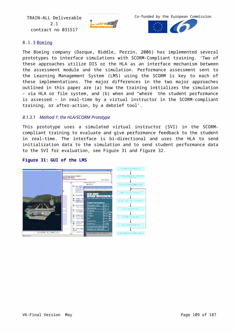
TRAIN-ALL Deliverable 2.1contract no 031517
Co-funded by the European Commission
Appendix A provides an overview of the TNO-RTI-1516 services. Extensions to the set of supported services are developed as required by customer needs. The design and implementation objectives for extensions or improvements will remain to provide an RTI high performance and a small footprint.
The TNO-RTI-1516 also provides three types of communication media (Shared Memory, UDP/IP and TCP/IP Ethernet). The TNO RTIs may be used in a mixed mode of 1.3 and 1516 versions.
Features TNO RTI: RTIexec and Fedex identical for RTI-1.3 and RTI-1516,
Mixed mode RTI-1.3 and RTI-1516 federation allowed,
Straightforward installation,
Software User Manual with worked examples.
Future developments:Further developments are foreseen in the support of new features regarding Quality of Service (QoS). Examples of possible QoS features are update deadlines, update rates, latency budget and multiple ownership. In addition, some proposals from the SISO ‘HLA Evolved’ studygroup are being considered for implementation.
Table 27: Supported Computer Platforms/CompilersProduct Supported Computer Platforms / Compilers
TNO Runtime Infrastructure TNO-RTI-1.3
Windows 2000/XP, MSVC++ 6.0 compiler
Windows 2000/XP, MSVC++ 7.1 compiler (.NET 2003)
Windows 2000/XP, MSVC++ 8.0 compiler (.NET 2005)
Linux 2.6 Kernel, RedHat Enterprise Linux 4.2, gcc 3.4.6 compiler
Irix 6.5 n32 mips3, MIPSpro 7.3.1.3m compiler
SunOS 5.9, SPRO 5.3 compiler
TNO Runtime Infrastructure TNO-RTI-1516
Windows 2000/XP, MSVC++ 7.1 compiler (.NET 2003)
Windows 2000/XP, MSVC++ 8.0 compiler (.NET 2005)
Linux 2.6 Kernel, RedHat Enterprise Linux 4.2, gcc 3.4.6 compiler
Irix 6.5 n32 mips3, MIPSpro 7.3.1.3m compiler
SunOS 5.9, SPRO 5.3 compiler
TSA CodegeneratorsThe TSA is supported by code-generators that translate the Component's or Federate's capabilities (specified in HLA-OMT format) into easily accessible object-oriented classes. The code generators hide complexities of the underlying interoperability standards and enables simulation protocol migration with minimal changes to the functional implementation of the Component or Federate. Two different types of codegenerators are available: one for the RCI’s C++ API and one that supports the RTI’s API directly. The latter one is specifically meant for interfacing to Java applications.
The TNO Java code generator is a tool for the automatic generation of java source code for HLA application developers. This tool uses the Federation Object Model (FOM) as input to produce a java sourcecode framework that provides the developer with basic/general HLA functionality, e.g. creating, joining and resigning federations, (un)subscribing, (un)publishing and the handling of objects, interactions and their attributes. The generated source code includes part of the Runtime Communication Infrastructure (RCI) functionality and therefore produces FOM-dependent ‘RCI-Lite’ java source code. The code generator generates a package ‘HLAInterface’. This package contains all
V6-Final Version May Page 109 of 140
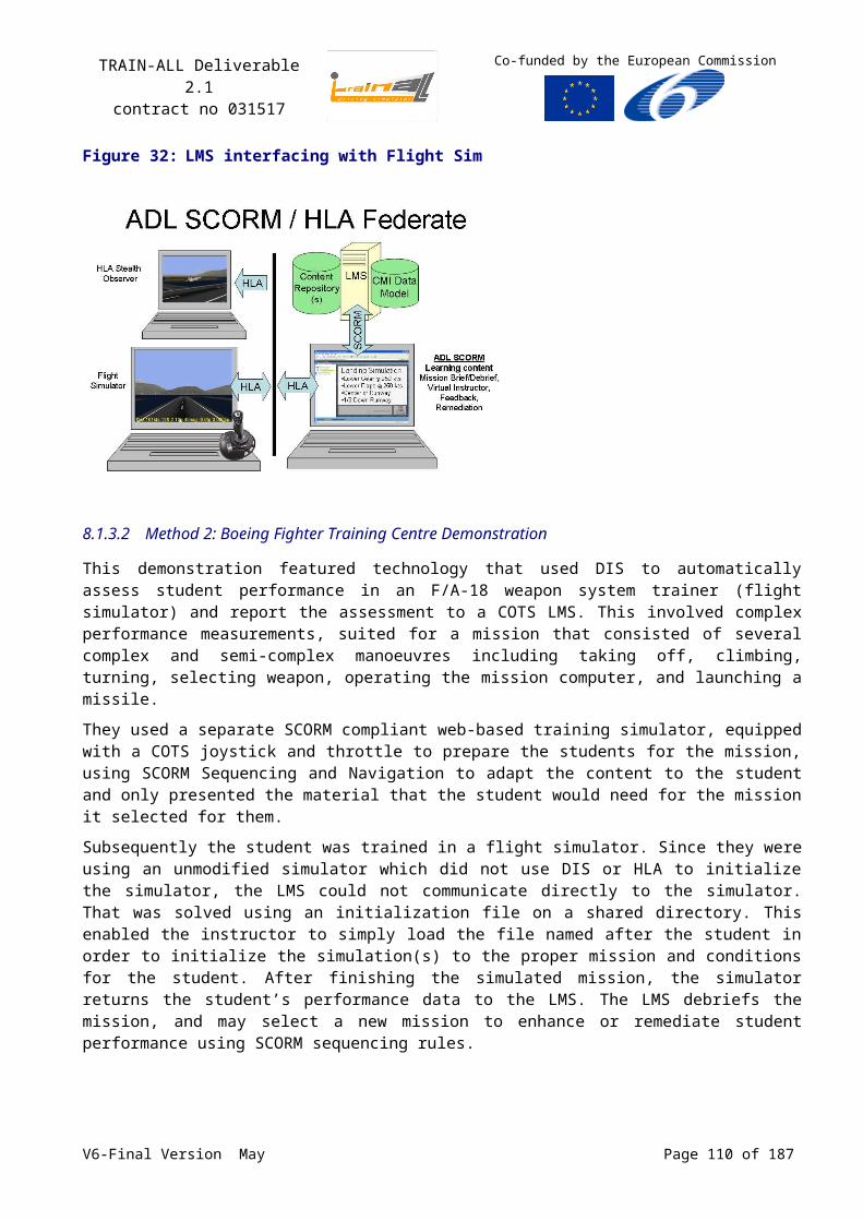
TRAIN-ALL Deliverable 2.1contract no 031517
Co-funded by the European Commission
classes from the SOM and does not require any modification. The simulation developer must integrate the generated code with his application. The strategy is:
1. prepare the OMT;
2. run the Java Codegenerator;
3. modify the generated JavaApp.java to your needs;
4. implement the ICallback class;
5. include package HLAInterface in the project.
The generated java code requires the DMSO RTI Javabindings.
Features of the RCI C++ codegenerator: C++ code generation for RCI based on SOM or FOM,
Codegenerator supports OMT 1.3 format for RCI-1.3 and XML 1516 OMT format for RCI-1516
Support of several data marshalling schemes, e.g. XDR, for network traffic,
Straightforward installation,
Software User Manual with worked examples.
Features of Java RTI codegenerator: java code generation for RTI 1.3NG6 based on SOM or FOM,
Codegenerator supports OMT 1.3 format for RTI 1.3NG6,
Straightforward installation,
Software User Manual with worked examples.
Future developments for the codegenerators:Further developments of the RCI codegenerator will follow any new features that are added to the RCI functionality. The java codegenerator will be updated to support RTI-1516. Further developments will follow any new features that are added to the RTI functionality.
Table 28: Supported Computer Platforms/CompilersProduct Supported Computer Platforms / Compilers
TNO RCI Codegenerator TNO-RCI-Codegen
Windows 2000/XP, MSVC++ 6.0 compiler
Windows 2000/XP, MSVC++ 7.1 compiler (.NET 2003)
Windows 2000/XP, MSVC++ 8.0 compiler (.NET 2005)
Linux 2.6 Kernel, RedHat Enterprise Linux 4.2, gcc 3.4.6 compiler
Irix 6.5 n32 mips3, MIPSpro 7.3.1.3m compiler
SunOS 5.9, SPRO 5.3 compiler
TNO Java Codegenerator TNO-Java-Codegen
Windows 2000/XP, MSVC++ 6.0 compiler
TNO Generaic Codegenerator
combined for RCI C++ and Java RTI
All platforms, Java Runtime Environment 1.5
All platforms, Java Runtime Environment 1.6
TNO Gateway
V6-Final Version May Page 110 of 140

TRAIN-ALL Deliverable 2.1contract no 031517
Co-funded by the European Commission
The TSA architectural concept supports a DIS/HLA Gateway. This tool is based on TNO’s middleware solutions for HLA and DIS, and is tailored to the specific requirements of the federation.
Features: Generic tool framework for development of DIS/HLA Gateways,
The HLA side of the Gateway is build on top of the RCI middleware layer. The DIS side of the Gateway uses either MAK VR-Link libraries or the TNO DIS library ‘Wodan’.
The HLA side uses C++ code generation based on the specific SOM or FOM,
FOM agility is provided through automatic as well as manual SOM to SOM mapping,
PDU agility is provided though a configuration file (ASCII) that allows the user to filter or map PDUs based on PDU type or Entity IDs,
Straightforward installation,
Software User Manual with worked examples.
Future developments:Additional PDUs will be added to the DIS side as and when required.
Table 29: TNO Gateway Computer Platforms/CompilersProduct Supported Computer Platforms / Compilers
TNO HLA-HLA Gateway Irix 6.5 n32 mips3, MIPSpro 7.3.1.3m compiler
Linux 2.4 Kernel, RedHat 9.0, gcc 3.2.2 compiler (to be updated)
Windows 2000/XP, MSVC++ X.Y compiler (to be released)
TNO DIS-HLA Gateway Irix 6.5 n32 mips3, MIPSpro 7.3.1.3m compiler
Linux 2.4 Kernel, RedHat 9.0, gcc 3.2.2 compiler (to be updated)
Windows 2000/XP, MSVC++ 6.0 compiler
Windows 2000/XP, MSVC++ 7.1 compiler (.NET 2003)
Windows 2000/XP, MSVC++ 8.0 compiler (.NET 2005)
TNO DIS-DIS Gateway Irix 6.5 n32 mips3, MIPSpro 7.3.1.3m compiler
Linux 2.4 Kernel, RedHat 9.0, gcc 3.2.2 compiler (to be updated)
Windows 2000/XP, MSVC++ X.Y compiler (to be released)
Supported services for TNO RTIsHLA 1.3 RTI Services TNO-
RTI 1.3
HLA IEEE 1516 RTI Services TNO-RTI
1516
FM createFederationExecution + createFederationExecution +
destroyFederationExecution + destroyFederationExecution +
joinFederationExecution + joinFederationExecution +
resignFederationExecution + resignFederationExecution +
registerFederationSynchronizationPoint + registerFederationSynchronizationPoint +
synchronizationPointRegistrationSucceeded † + synchronizationPointRegistrationSucceeded † +
synchronizationPointRegistrationFailed † + synchronizationPointRegistrationFailed † +
announceSynchronizationPoint † + announceSynchronizationPoint † +
V6-Final Version May Page 111 of 140
TRAIN-ALL Deliverable 2.1contract no 031517
Co-funded by the European Commission
HLA 1.3 RTI Services TNO-RTI 1.3
HLA IEEE 1516 RTI Services TNO-RTI
1516
synchronizationPointAchieved + synchronizationPointAchieved +
federationSynchronized † + federationSynchronized † +
requestFederationSave + requestFederationSave +
initiateFederateSave † + initiateFederateSave † +
federateSaveBegun + federateSaveBegun +
federateSaveComplete + federateSaveComplete +
federateSaveNotComplete + federateSaveNotComplete +
federationSaved † + federationSaved † +
federationNotSaved † + federationNotSaved † +
queryFederationSaveStatus
federationSaveStatusResponse †
requestFederationRestore + requestFederationRestore +
requestFederationRestoreSucceeded † + requestFederationRestoreSucceeded † +
requestFederationRestoreFailed † + requestFederationRestoreFailed † +
federationRestoreBegun † + federationRestoreBegun † +
initiateFederateRestore † + initiateFederateRestore † +
federateRestoreComplete + federateRestoreComplete +
federateRestoreNotComplete + federateRestoreNotComplete +
federationRestored † + federationRestored † +
federationNotRestored † + federationNotRestored † +
queryFederationRestoreStatus
federationRestoreStatusResponse †
HLA 1.3 RTI Services TNO-RTI 1.3
HLA IEEE 1516 RTI Services TNO-RTI
1516
DM publishObjectClass + publishObjectClassAttributes +
unpublishObjectClass + unpublishObjectClass +
unpublishObjectClassAttributes +
publishInteractionClass + publishInteractionClass +
unpublishInteractionClass + unpublishInteractionClass +
subscribeObjectClassAttributes + subscribeObjectClassAttributes +
unsubscribeObjectClass + unsubscribeObjectClass +
unsubscribeObjectClassAttributes +
subscribeInteractionClass + subscribeInteractionClass +
unsubscribeInteractionClass + unsubscribeInteractionClass +
startRegistrationForObjectClass † startRegistrationForObjectClass †
stopRegistrationForObjectClass † stopRegistrationForObjectClass †
turnInteractionsOn † turnInteractionsOn †
V6-Final Version May Page 112 of 140
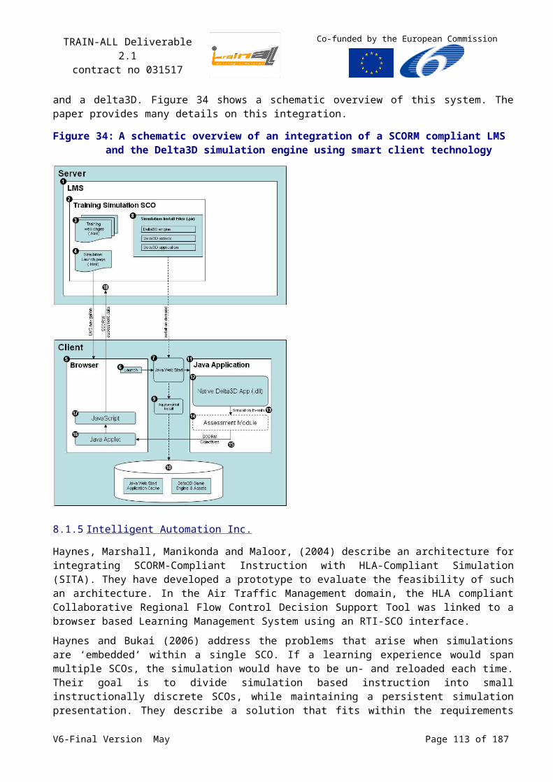
TRAIN-ALL Deliverable 2.1contract no 031517
Co-funded by the European Commission
HLA 1.3 RTI Services TNO-RTI 1.3
HLA IEEE 1516 RTI Services TNO-RTI
1516
turnInteractionsOff † turnInteractionsOff †
HLA 1.3 RTI Services TNO-RTI 1.3
HLA IEEE 1516 RTI Services TNO-RTI 1516
OM reserveObjectInstanceName +
objectInstanceNameReservationSucceeded +
objectInstanceNameReservationFailed +
registerObjectInstance + registerObjectInstance +
discoverObjectInstance † + discoverObjectInstance † +
updateAttributeValues + updateAttributeValues +
reflectAttributeValues † + reflectAttributeValues † +
sendInteraction + sendInteraction +
receiveInteraction † + receiveInteraction † +
deleteObjectInstance + deleteObjectInstance +
removeObjectInstance † + removeObjectInstance † +
localDeleteObjectInstance + localDeleteObjectInstance +
changeAttributeTransportationType changeAttributeTransportationType
changeInteractionTransportationType changeInteractionTransportationType
attributesInScope † attributesInScope †
attributesOutOfScope † attributesOutOfScope †
requestObjectAttributeValueUpdate + requestObjectAttributeValueUpdate +
requestClassAttributeValueUpdate + requestClassAttributeValueUpdate +
provideAttributeValueUpdate † + provideAttributeValueUpdate † +
turnUpdatesOnForObjectInstance † turnUpdatesOnForObjectInstance †
turnUpdatesOffForObjectInstance † turnUpdatesOffForObjectInstance †
HLA 1.3 RTI Services TNO-RTI 1.3
HLA IEEE 1516 RTI Services TNO-RTI
1516
OSM
unconditionalAttributeOwnershipDivestiture
unconditionalAttributeOwnershipDivestiture
negotiatedAttributeOwnershipDivestiture negotiatedAttributeOwnershipDivestiture
requestAttributeOwnershipAssumption † requestAttributeOwnershipAssumption †
attributeOwnershipDivestitureNotification † requestDivestitureConfirmation †
confirmDivestiture
attributeOwnershipAcquisitionNotification † attributeOwnershipAcquisitionNotification †
attributeOwnershipAcquisition attributeOwnershipAcquisition
attributeOwnershipAcquisitionIfAvailable attributeOwnershipAcquisitionIfAvailable
attributeOwnershipUnavailable † attributeOwnershipUnavailable †
V6-Final Version May Page 113 of 140
TRAIN-ALL Deliverable 2.1contract no 031517
Co-funded by the European Commission
HLA 1.3 RTI Services TNO-RTI 1.3
HLA IEEE 1516 RTI Services TNO-RTI
1516
requestAttributeOwnershipRelease † requestAttributeOwnershipRelease †
attributeOwnershipReleaseResponse attributeOwnershipDivestitureIfWanted
cancelNegotiatedAttributeOwnershipDivestiture
cancelNegotiatedAttributeOwnershipDivestiture
cancelAttributeOwnershipAcquisition cancelAttributeOwnershipAcquisition
confirmAttributeOwnershipAcquisitionCancellation †
confirmAttributeOwnershipAcquisitionCancellation †
queryAttributeOwnership queryAttributeOwnership
informAttributeOwnership † informAttributeOwnership †
attributeIsNotOwned † attributeIsNotOwned †
attributeOwnedByRTI † attributeIsOwnedByRTI †
isAttributeOwnedByFederate isAttributeOwnedByFederate
HLA 1.3 RTI Services TNO-RTI 1.3
HLA IEEE 1516 RTI Services TNO-RTI
1516
TM enableTimeRegulation + enableTimeRegulation +
timeRegulationEnabled † + timeRegulationEnabled † +
disableTimeRegulation + disableTimeRegulation +
enableTimeConstrained + enableTimeConstrained +
timeConstrainedEnabled † + timeConstrainedEnabled † +
disableTimeConstrained + disableTimeConstrained +
timeAdvanceRequest + timeAdvanceRequest +
timeAdvanceRequestAvailable + timeAdvanceRequestAvailable +
nextEventRequest + nextMessageRequest +
nextEventRequestAvailable + nextMessageRequestAvailable +
flushQueueRequest flushQueueRequest
timeAdvanceGrant † + timeAdvanceGrant † +
enableAsynchronousDelivery + enableAsynchronousDelivery +
disableAsynchronousDelivery + disableAsynchronousDelivery +
queryLBTS + queryGALT +
queryFederateTime + queryLogicalTime +
queryMinNextEventTime queryLITS
modifyLookahead + modifyLookahead +
queryLookahead + queryLookahead +
retract retract
requestRetraction † requestRetraction †
changeAttributeOrderType changeAttributeOrderType
changeInteractionOrderType changeInteractionOrderType
V6-Final Version May Page 114 of 140
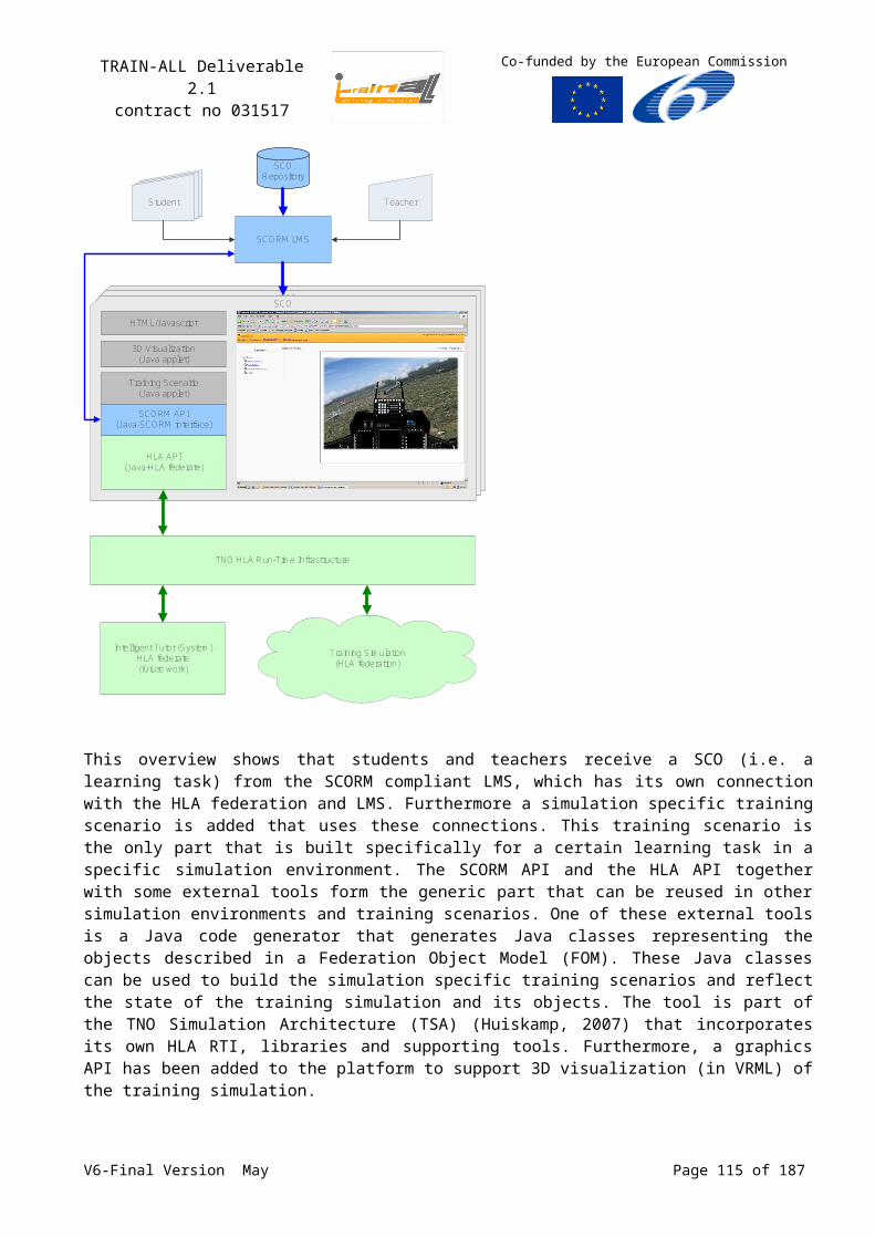
TRAIN-ALL Deliverable 2.1contract no 031517
Co-funded by the European Commission
HLA 1.3 RTI Services TNO-RTI 1.3
HLA IEEE 1516 RTI Services TNO-RTI
1516
DDM
createRegion createRegion
notifyAboutRegionModification commitRegionModifications
deleteRegion deleteRegion
registerObjectInstanceWithRegion registerObjectInstanceWithRegion
registerObjectInstanceWithRegion registerObjectInstanceWithRegion
associateRegionForUpdates associateRegionForUpdates
unassociateRegionForUpdates unassociateRegionForUpdates
subscribeObjectClassAttributesWithRegion
subscribeObjectClassAttributesWithRegion
unsubscribeObjectClassWithRegion unsubscribeObjectClassWithRegion
subscribeInteractionClassWithRegion subscribeInteractionClassWithRegion
unsubscribeInteractionClassWithRegion unsubscribeInteractionClassWithRegion
sendInteractionWithRegion sendInteractionWithRegion
sendInteractionWithRegion sendInteractionWithRegion
requestClassAttributeValueUpdateWithRegion
requestClassAttributeValueUpdateWithRegion
HLA 1.3 RTI Services TNO-RTI 1.3
HLA IEEE 1516 RTI Services TNO-RTI
1516
SS getObjectClassHandle + getObjectClassHandle +
getObjectClassName + getObjectClassName +
getAttributeHandle + getAttributeHandle +
getAttributeName + getAttributeName +
getInteractionClassHandle + getInteractionClassHandle +
getInteractionClassName + getInteractionClassName +
getParameterHandle + getParameterHandle +
getParameterName + getParameterName +
getObjectInstanceHandle + getObjectInstanceHandle +
getObjectInstanceName + getObjectInstanceName +
getRoutingSpaceHandle
getRoutingSpaceName
getDimensionHandle getDimensionHandle
getDimensionName getDimensionName
getDimensionUpperBound
getAttributeRoutingSpaceHandle getAvailableDimensionsForClassAttribute
getObjectClass + getKnownObjectClassHandle +
getInteractionRoutingSpaceHandle getAvailableDimensionsForInteractionClass
getTransportationHandle getTransportationType
V6-Final Version May Page 115 of 140
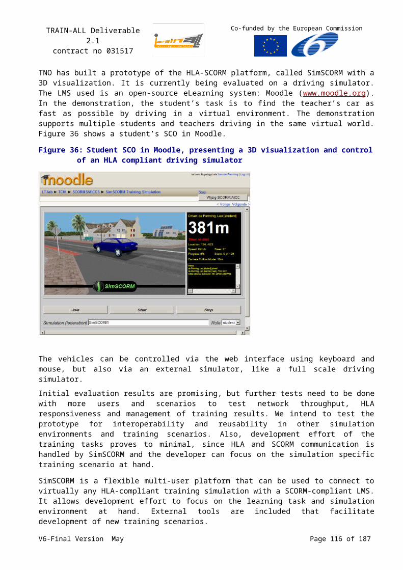
TRAIN-ALL Deliverable 2.1contract no 031517
Co-funded by the European Commission
HLA 1.3 RTI Services TNO-RTI 1.3
HLA IEEE 1516 RTI Services TNO-RTI
1516
getTransportationName getTransportationName
getOrderingHandle getOrderType
getOrderingName getOrderName
enableClassRelevanceAdvisorySwitch enableClassRelevanceAdvisorySwitch
disableClassRelevanceAdvisorySwitch disableClassRelevanceAdvisorySwitch
enableAttributeRelevanceAdvisorySwitch enableAttributeRelevanceAdvisorySwitch
disableAttributeRelevanceAdvisorySwitch disableAttributeRelevanceAdvisorySwitch
enableAttributeScopeAdvisorySwitch enableAttributeScopeAdvisorySwitch
disableAttributeScopeAdvisorySwitch disableAttributeScopeAdvisorySwitch
enableInteractionRelevanceAdvisorySwitch
enableInteractionRelevanceAdvisorySwitch
disableInteractionRelevanceAdvisorySwitch
disableInteractionRelevanceAdvisorySwitch
getRegionToken
getRegion
getDimensionHandleSet
getRangeBounds
setRangeBounds
normalizeFederateHandle
normalizeServiceGroup
constructor RTIambassador + constructor RTIambassador +
destructor RTIambassador + destructor RTIambassador +
evokeCallback
tick + evokeMultipleCallbacks +
enableCallbacks
disableCallbacks
V6-Final Version May Page 116 of 140
TRAIN-ALL Deliverable 2.1contract no 031517
Co-funded by the European Commission
Annex HSCORM
SCORM is a specification of the Advanced Distributed Learning (ADL) initiative, which is governed by the US Secretary of Defence. The current SCORM 2004 3rd Edition standard is already the 6th generation SCORM standards. SCORM 2004 consists of three sets of definitions:
1. Content Aggregation Model (CAM)
2. Sequencing and Navigation (S&N)
3. Run-time Environment (RTE)
These standards are described in detail in three books. A fourth book gives an overview of SCORM 2004. Table 30 shows the topics covered by these four books:
Table 30: The topics covered in the primary SCORM 2004 booksSCORM Book Concepts Covered Key SCORM Technologies
CoveredAreas of Overlap
Overview High-level conceptual information
Introduction to numerous high-level elements of SCORM terminology
Covers areas of the CAM, RTE and SN books at a high level
Content Aggregation Model (CAM)
Assembling, labelling and packaging of learning content
SCO, Asset, Content Aggregation, Package, Package Interchange File (PIF), Metadata, Manifest, Sequencing Information, Navigation Information
SCOs and manifests. SCOs communicate with an LMS via the RTE. Manifests contain Sequencing and Navigation information
Run-Time Environment (RTE)
LMS’s management of the RTE, which includes launch, content to LMS communication, tracking, data transfer and error handling
API, API Instance, Launch, Session Methods, Data Transfer Methods, Support Methods, Temporal Model, Run-Time Data Model
SCOs are described in the CAM book, are content objects which use the RTE
Sequencing and Navigation (SN)
Sequencing content and navigation
Activity Tree, Learning Activities, Sequencing Information, Navigation Information, Navigation Data Model
Sequencing and Navigation affects how content is assembled in a manifest
We will now give an overview of the most relevant concepts in SCORM 2004. We kept to the original text as much as possible, and definitions, tables and pictures are taken directly from the relevant books.
H1 SCORM Content Aggregation Model (CAM)
The SCORM CAM model describes the assembling, labelling and packaging of learning content. It consists of several components:
1. Content Model: Nomenclature defining the content components of a learning experience.
2. Content Packaging: Defines how to represent the intended behaviour of a learning experience (Content Structure) and how to aggregate activities of learning resources for movement between different environments (Content Packaging).
V6-Final Version May Page 117 of 140

TRAIN-ALL Deliverable 2.1contract no 031517
Co-funded by the European Commission
3. Metadata: A mechanism for describing specific instances of the components of the content model.
4. Sequencing and Navigation: A rule-based model for defining a set of rules that describes the intended sequence and ordering of activities. The activities may or may not reference learning resources to be delivered to the learner.
H2 SCORM Content Model
The most relevant key concepts in the SCORM Content Model are: Assets, Sharable Content Objects (SCO), Metadata, Content Aggregation, Package, Package Information File
Assets
The Asset is ‘the basic building block of a learning resource., see Figure 43 Assets are an electronic representation of media, such as text, images, sound, assessment objects or any other piece of data that can be rendered by a Web client and presented to a learner.’
Figure 43: Assets are the building blocks of a learning resource
Sharable Content ObjectsA Sharable Content Object (SCO) is ‘a collection of one or more Assets that represent a single launchable learning resource that uses the SCORM RTE to communicate with an LMS. A SCO represents the lowest level of granularity of a learning resource that is tracked by an LMS’, see Figure44.
V6-Final Version May Page 118 of 140
TRAIN-ALL Deliverable 2.1contract no 031517
Co-funded by the European Commission
Figure 44: A Sharable Content Object (SCO), the smallest learning resource that can be addressed by a learning management system
AssetJavaScriptFuntions
AssetHTML
Fragment
AssetFlashObject
AssetJPEGImage
AssetWAVAudio
AssetMP3 Audio
Sharable Content Object (SCO)
Learning activitiesA learning activity may be loosely described as a meaningful unit of instruction; it is conceptually something the learner does while progressing through instruction. A learning activity may provide a learning resource (SCO or Asset) to the learner or it may be composed of several sub-activities.’, see Figure 45. In general, activities are nested, for example in courses, chapters, modules etc. Activities that consist of other activities are also called Clusters. The SCORM Sequencing and Navigation standards provide more details on how behaviours can be defined for Activities and Clusters.
Figure 45: Students perform learning activities, which can consist of one or more SCOs, Assets or sub Activities
V6-Final Version May Page 119 of 140
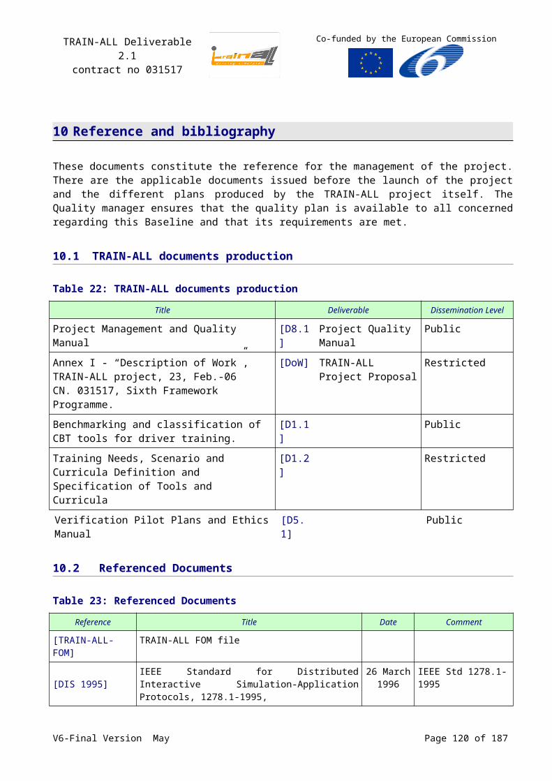
TRAIN-ALL Deliverable 2.1contract no 031517
Co-funded by the European Commission
All learning activities have the following characteristics:
Learning activities have a discrete start and finish.
Learning activities have well-defined completion and mastery conditions.
Learning activities can consist of sub-activities, nested to any depth.
(Attempts on) Learning activities occur in context of (attempts on) their parent activity, if one exists.
Content Organization‘A Content Organization is a representation or map that defines the intended use of the content through structured units of instruction (Activities), see Figure 46. The map shows how Activities relate to one another.’ ‘The intended sequencing of Activities is defined as part of the Content Organization, by structuring Activities in relation to one another and by associating sequencing information with each Activity. The LMS is responsible for interpreting the sequencing information described in the Content Organization and applying sequencing behaviours to control the actual sequence of the learning resources at run-time.’ ‘Sequencing only applies to activities.’
Figure 46: Conceptual illustration of a content organization, the structured map of activities that the students perform in a lesson or course
H3 SCORM Content Packaging
‘Once learning content is designed and built, there is a need to make the content available to learners, authoring tools, repositories or LMSs. The IMS Content Packaging Specification was designed to provide a standard way to structure and exchange learning content’, see Figure 47.
The purpose of the Content Package is to provide a standardized way to exchange learning content between different systems or tools. The Content Package also provides a place for describing the structure (or organization) and the intended behaviour of a collection of learning content.
Content packages are expected to be used to move learning content or collections of learning content between LMSs, development tools and content repositories. The IMS Content Packaging Specification [3] provides a common “input/output” format that any system can support.
SCORM Content Packaging is a set of specific requirements and guidance, or application profiles, of the IMS Content Packaging Specification. SCORM Content Packages adheres strictly to the IMS Content Packaging Specification and provides additional explicit requirements and implementation guidance for packaging Assets, SCOs and Content Organization.
V6-Final Version May Page 120 of 140
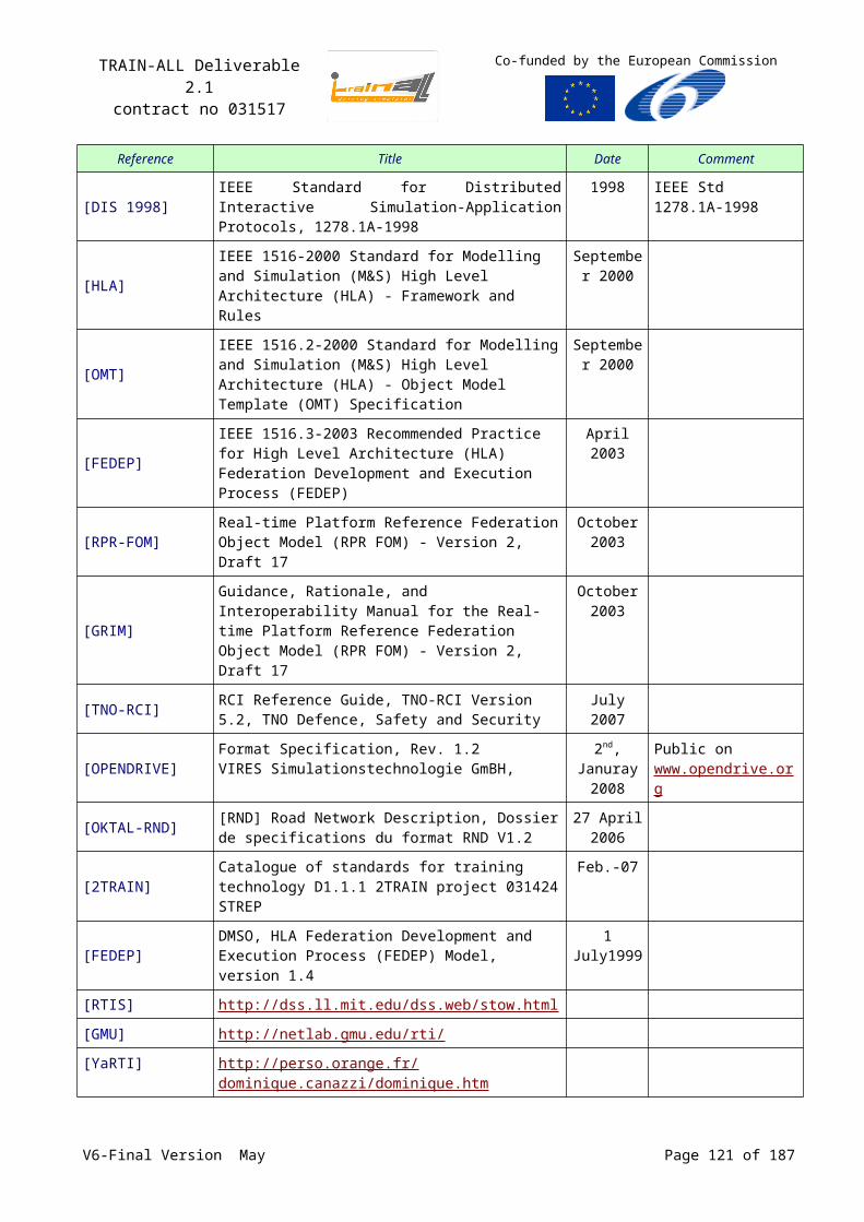
TRAIN-ALL Deliverable 2.1contract no 031517
Co-funded by the European Commission
A content package consists of two major components:
An XML document describing the structure and associated resources of the package file (a ‘manifest file’), acting as a ‘packaging slip’ for the content.
The content (i.e., physical files) making up the content package
Figure 47: The SCORM content package, with a manifest file describing the content in detail
ManifestThe manifest file is an XML document representing the information needed to describe the contents of the package. The manifest is composed of four major sections, see Figure 47:
1. Metadata: Data describing the content package as a whole.
2. Organizations: Contains the content structure or organization of the learning resources making up a stand-alone unit or units of instruction.
3. Resources: Defines the learning resources bundled in the content package.
4. (sub)Manifest(s): Describes any logically nested units of instruction (which can be treated as stand-alone units).
H.4:SCORM Metadata
All SCORM components can be tagged with metadata ( ‘data about data’) to allow them to be stored in and retrieved from repositories. The metadata defined is directly based on the IEEE 1484.12.1-2002 Learning Object Metadata (LOM) [11] standard and the IEEE 1484.12.3 Standard for Extensible Markup Language (XML) Binding for Learning Object Metadata Data Model [14]. The IEEE provides roughly 64 metadata elements that can be used to describe SCORM Content Model Components.
V6-Final Version May Page 121 of 140
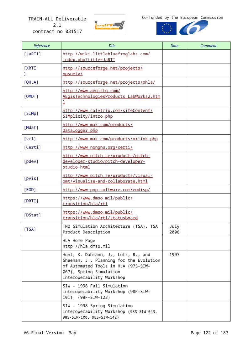
TRAIN-ALL Deliverable 2.1contract no 031517
Co-funded by the European Commission
IEEE LOM Information ModelThe IEEE LOM Information Model describes the set of data elements that are available to build metadata. The LOM Information Model is broken up into nine categories. These categories are based on the definitions found in the LOM Information Model. The nine categories of metadata elements are described here, and their child elements are listed:
1. The General category can be used to describe general information about the SCORM Content Model Component as a whole. It contains the following child elements:
• <identifier>
• <title>
• <language>
• <description>
• <keyword>
• <coverage>
• <structure>
• <aggregationLevel>
2. The Life Cycle category can be used to describe features related to the history and current state of the SCORM Content Model Component and those who have affected the component during its evolution. It contains the following child elements:
• <version>
• <status>
• <contribute>
3. The Meta-metadata category can be used to describe information about the metadata record itself (rather than the SCORM Content Model Component that the record describes). It contains the following child elements:
• <identifier>
• <contribute>
• <metadataSchema>
• <language>
4. The Technical category can be used to describe technical requirements and characteristics of the SCORM Content Model Components. It contains the following child elements:
• <format>
• <size>
• <location>
• <requirement>
• <installationRemarks>
• <otherPlatformRequirements>
• <duration>
5. The Educational category can be used to describe the educational and pedagogic characteristics of the SCORM Content Model Component. It contains the following child elements:
• <interactivityType>
• <learningResourceType>
• <interactivityLevel>
• <semanticDensity>
• <intendedEndUserRole>
• <context>
• <typicalAgeRange>
• <difficulty>
• <typicalLearningTime>
• <description>
• <language>
6. The Rights category can be used to describe the intellectual property rights and conditions of use for the SCORM Content Model Component. It contains the following child elements:
• <cost>
• <copyrightAndOtherRestrictions>
• <description>
V6-Final Version May Page 122 of 140

TRAIN-ALL Deliverable 2.1contract no 031517
Co-funded by the European Commission
7. The Relation category can be used to describe features that define the relationship between this SCORM Content Model Component and other targeted components. It contains the following child elements:
• <kind> • <resource>
8. The Annotation category can be used to provide comments on the educational use of the SCORM Content Model Component and information on when and by whom the comments were created. It contains the following child elements:
• <entity>
• <date>
• <description>
9. The Classification category can be used to describe where the SCORM Content Model Component falls within a particular classification system It contains the following child elements:
•
<purpose>
• <taxonPath>
• <description>
• <keyword>
H.5:SCORM sequencing and Navigation
The SCORM standard not only specifies content packaging and data tagging, but also specifies how these learning objects can be sequenced (i.e. in a lesson) or navigated (i.e. by the learner or an automated system)
‘The SCORM Sequencing and Navigation (SN) book defines a method for representing the intended behaviour of a learning experience such that any SCORM conformant LMS will sequence learning activities in a consistent way. It also defines the required behaviours and functionality that SCORM conformant LMSs must implement to process sequencing information at run-time. More specifically, it describes the branching and flow of learning activities in terms of an Activity Tree, based on the results of a learner’s interactions with content objects and an authored sequencing strategy. An Activity Tree is a conceptual structure of learning activities managed by the LMS for each learner as shown in Figure 48. It is a general term that represents an instance of hierarchical learning activities and the corresponding sequencing information for the interoperable application of specified sequencing behaviours’.
Figure 48: Activity tree
SequencingSCORM Sequencing is based on the IMS Simple Sequencing standard [IMS] which defines a method for representing the intended behaviour of an authored learning experience such that any LMS can sequence discrete learning activities in a consistent way. Simple Sequencing is labelled as simple because it includes a limited number of widely used sequencing behaviours, not because the
V6-Final Version May Page 123 of 140
TRAIN-ALL Deliverable 2.1contract no 031517
Co-funded by the European Commission
specification itself is simple. Simple Sequencing is not all-inclusive. In particular, Simple Sequencing does not address, but does not necessarily preclude, artificial intelligence-based sequencing, schedule-based sequencing, sequencing requiring data from closed external systems and services (e.g., sequencing of embedded simulations), collaborative learning, customized learning, or synchronization between multiple parallel learning activities.
SCORM Sequencing knows several control modes, which specify how learning activities are sequenced, including free choice, forward only, and how to deal with multiple attempts.
NavigationNavigation is the process by which a learner and an LMS cooperate to identify navigation requests to realize a learning experience. Typically, the LMS will provide some set of user interface devices that the learner may use to indicate a desired navigation requests. In some cases, content developers may wish to indicate that the LMS should not provide those user interface devices; instead, the content will provide them. Sometimes the content may provide user interface devices in addition to those provided by the LMS. In all cases, navigation requests correspond to learner or content-directed movement through an Activity Tree.
The SCORM Navigation Model defines a set of navigation events that can be triggered by a learner through an LMS and content provided user interface devices or directly by SCOs. These include: Start, Resume-all, Continue, Previous, Choose, Abandon, Abandon-all, Suspend-all, Unqualified exit, Exit all.
‘The SCORM SN book describes how learner-initiated and system-initiated navigation events can be triggered and processed, resulting in the identification of learning activities for delivery. Each learning activity identified for delivery will have an associated content object. The SCORM RTE book describes how these content objects are launched. The SCORM RTE model also describes how the LMS manages the resulting learning experience and how that learning experience may affect the Activity Tree.’
H.6:SCORM Run Time Environment
The SCORM Run-Time Environment (RTE) book describes the requirements that allow for interoperability of content across different LMSs. That is, ‘a standardized content launch process, standardized methods of effecting communication between content and LMSs and standardized data model elements used for passing information about the learner’s interactions with the content. The RTE covers the requirements of SCOs and their use of a standard communication mechanism as well as the data that can be transferred to and from the LMS using this communication mechanism.’
‘The purpose of the SCORM RTE is to provide for interoperability between SCOs and LMSs. SCORM provides a means for learning content to be interoperable across multiple LMSs regardless of the tools used to create the content. For this to be possible, there must be a common way to launch content, a common way for content to communicate with an LMS, and predefined data elements that are exchanged between an LMS and content during its execution. The three components of the SCORM RTE are defined as:
Launch“Launch” defines the conventions by which LMSs and SCORM conforming content will be delivered and displayed to the learner.
APIThe API is the communication mechanism for informing the LMS of the conceptual communication state between a content object and an LMS (e.g., initialized, terminated and/or in an error condition), and is used for retrieving and storing data (e.g., score, time limits, etc.) between the LMS and the SCO. In addition, the functions allow SCORM content to “set” and “get” data on the LMS, such as V6-Final Version May Page 124 of 140
TRAIN-ALL Deliverable 2.1contract no 031517
Co-funded by the European Commission
assessment results, and to check for and address any errors that occur during these processes. This “get” and “set” data is used to determine the state of the learner’s progress through the content and consequent sequencing decisions.
Data ModelA Data Model is a standard set of data model elements used to define the information being tracked for a SCO, such as the SCO’s completion status or a score from an assessment such as a quiz or a test. In its simplest form, the data model defines data model elements that both the LMS and SCO are expected to “know about.” The LMS must maintain the state of SCO’s data model elements across learner sessions, and the SCO must utilize only these predefined data model elements to ensure reuse across multiple systems.
Figure 49: Interface between RTE and LMS
The purpose of establishing a common data model is to ensure that a defined set of information about SCOs can be tracked by different LMS environments. The SCORM Run-Time Environment Data Model is based on the 1484.11.1 Standard for Learning Technology - Data Model for Content Object Communication [21] standard produced by the IEEE LTSC CMI. 1484.11.1 is a standard that defines a set of data model elements that can be used to communicate information from a content object (i.e., SCO in SCORM) to an LMS. This set of data includes, but is not limited to, information about the learner, interactions that the learner had with the SCO, objective information, success status and completion status. This information may be vital for many purposes. This data can be used to track the learner’s progress and status, aid in sequencing decisions and report on the overall learner interaction with the SCO.
For instance, when transmitting a test score for a learner, a SCO would use the SCORM Data Model element known as “cmi.score.scaled” to inform the LMS how the learner performed. This and all other SCORM Data Model elements are described in detail in the SCORM RTE book. Table 31 shows all the Data Model Elements, with a brief description.
Table 31: Data Model Elements for run time communication between SCO and LMS
Data Model Element Description
Comments From Learner Contains text from the learner.
Comments From LMS Contains comments and annotations intended to be made available to the learner.
Completion Status Indicates whether the learner has completed the SCO.
Completion Threshold Identifies a value against which the measure of the progress the learner has made toward completing the SCO can be compared to determine whether the SCO should be considered completed.
Credit Indicates whether the learner will be credited for performance in this SCO.
V6-Final Version May Page 125 of 140
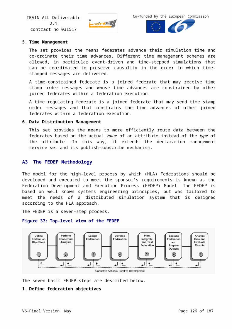
TRAIN-ALL Deliverable 2.1contract no 031517
Co-funded by the European Commission
Data Model Element Description
Entry Contains information that asserts whether the learner has previously accessed the SCO.
Exit Indicates how or why the learner left the SCO.
Interactions Defines information pertaining to an interaction for the purpose of measurement or assessment.
Launch Data Provides data specific to a SCO that the SCO can use for initialization.
Learner Id Identifies the learner on behalf of whom the SCO instance was launched.
Learner Name Represents the name of the learner.
Learner Preference Specifies learner preferences associated with the learner’s use of the SCO.
Location Represents a location in the SCO.
Maximum Time Allowed Indicates the amount of accumulated time the learner is allowed to use a SCO in the learner attempt.
Mode Identifies the modes in which the SCO may be presented to the learner.
Objectives Specifies learning or performance objectives associated with a SCO.
Progress Measure Identifies a measure of the progress the learner has made toward completing the SCO.
Scaled Passing Score Identifies the scaled passing score for a SCO.
Score Identifies the learner’s score for the SCO.
Session Time Identifies the amount of time that the learner has spent in the current learner session for the SCO.
Success Status Indicates whether the learner has mastered the SCO.
Suspend Data Provides information that may be created by a SCO as a result of a learner accessing or interacting with the SCO.
Time Limit Action Indicates what the SCO should do when the maximum time allowed is exceeded.
Total Time Identifies the sum of all of the learner’s learner session times accumulated in the current learner attempt prior to the current learner session.
V6-Final Version May Page 126 of 140
TRAIN-ALL Deliverable 2.1contract no 031517
Co-funded by the European Commission
Annex I QTI
‘The IMS Question & Test Interoperability (QTI) specification describes a data model for the representation of question (assessment item) and test (assessment test) data and their corresponding results reports.’ It ‘enables the exchange of this item, test, and results data between authoring tools, item banks, test constructional tools, learning systems, and assessment delivery systems.’
QTI is designed to:
Provide a well documented content format for storing and exchanging items independent of the authoring tool used to create them.
Support the deployment of item banks across a wide range of learning and assessment delivery systems.
Provide a well documented content format for storing and exchanging tests independent of the test construction tool used to create them.
Support the deployment of items, item banks, and tests from diverse sources in a single learning or assessment delivery system.
Provide systems with the ability to report test results in a consistent manner.
The data models described in QTI are to a large extent compliant to the data models used in SCORM.
QTI adds two a specific categories to the LOM standard:
1. The qtiMetadata category is used for recording QTI specific information on testitems:
• <itemtemplate>
• <timedependent>
• <composite>
• <interactiontype>
• <feedbacktype>
• <solutionavailable>
• <toolname>
• <toolversion>
• <toolvendor>
2. The usageData category is used for recording QTI specific information on the usage data (item statistics) of test items:
• <glossary>
• <name>
• <context>
• <caseCount>
• <stdError>
• <stdDeviation>
• <lastupdated>
• <targetobject>
• <identifier>
• <partIdentifier>
• <ordinaryStatistic>
• <categorizedStatistic>
V6-Final Version May Page 127 of 140
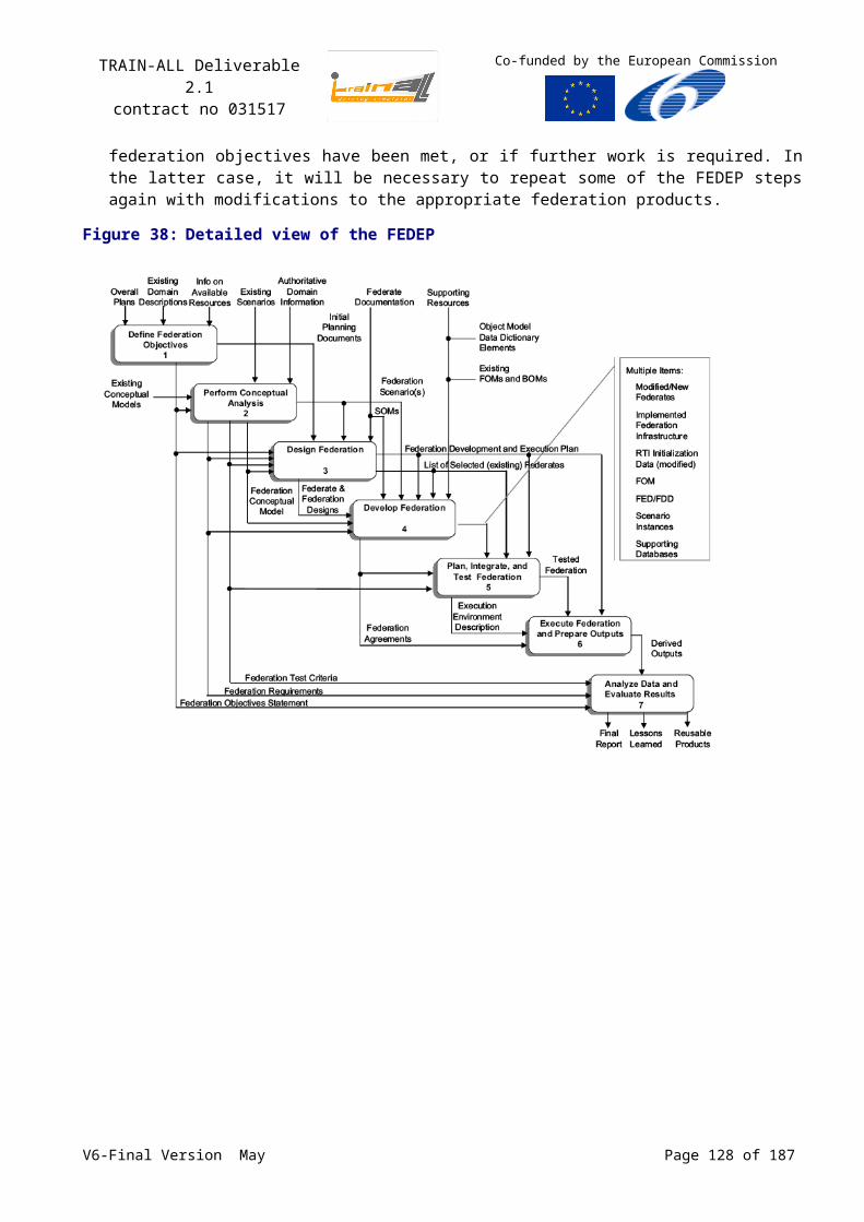
TRAIN-ALL Deliverable 2.1contract no 031517
Co-funded by the European Commission
Annex J Military Scenario Definition Language
The Military Scenario Definition Language (MSDL), aims at interoperability of scenarios independent of their application. This standard has its roots in land-base military operations, and is currently being extended to accommodate joint scenarios (with land, sea and air components).
MSDL describes the current situation (tn) and the course of action (tn+1) in the unfolding scenario. Such scenarios are made up of Core, Common and Custom data, in which MSDL primarily describes Core and Common data, and leaves Custom data to each individual application. In its description of a scenario MSDL relies on the 5W’s of the Battle Management Language: What, When, Where, Who and Why. This information is combined with additional data like options, plans, environment and installations. Just like SCORM and QTI, the MSDL standard describes in detail how this information is stored in XML.
These areas are worked out in detail in a schematic format. Figure 50 shows an overview of the MSDL XML schema, containing the following elements: Options, Plan, Environment, Force Structure, Task Organizations, Installations, Overlays, Tactical Graphics, MOOTW Graphics, and Threats. Each element is identified by a Universal Unique Identifier, stored in an XML element named “ObjectHandle”. The top level XML schema presented here (MilitaryScenario.xsd) contains only one XML element and forms the root element of the MSDL scenario. All other elements are specified in the msdlElements.xsd schema. MSDL includes scenario specifications in three principle areas:
Scenario Options – The basic planning model, data standards being used, and application specific options.
Situation – The task organizations, tactical graphics, threat, and environment/weather information.
Plan & Course of Action – Scenario objectives, executive summary (OPORD), documents, and courses of action.
A simulation scenario contains:
A reference to the appropriate terrain database to utilize,
Data for any additional creation of environment objects,
Data for the weather attributes across the database,
Data for sides, forces, and their relationships,
Entities and units and their specific data attributes including: entity or unit composition, resource loads, subordinates, locations, orientations and initial damage state,
Order data,
Control measures and overlay data,
A reference to the data collection specifications,
Specific simulation data such as the execution is to be batch or interactive,
General scenario data such as a description of the scenario contents,
General categorization data for the scenario to enable searches.
For the standard definition of the data elements in MSDL we refer to the MSDL specification (www.sisostds.org | SISO products | Product development groups | Military Scenario Definition Language). Here we will describe the elements in MSDL relevant for Train-all, excluding typical military aspects like Overlays, tactical graphics, MOOTW graphics, threats.
V6-Final Version May Page 128 of 140
TRAIN-ALL Deliverable 2.1contract no 031517
Co-funded by the European Commission
Figure 50: The top-level of the MSDL schema, containing the main elements
OptionsThe Options are used to identify how task organizations are specified (entity or aggregate based), the data standards being used by the scenario, and any application specific options that have been created by the C2 planning application(s) which created the scenario. It includes information on Organization and Unit, Coordinate System, Enumeration Standard and Version, and Application specific options of the scenario.
EnvironmentEnvironment information includes the absolute scenario time (initial time), identification of the terrain, and synoptic weather. Terrain is identified with a free format field indicating the terrain source. Weather includes information on: temperature, moon, sun, wind, twilight, relative humidity, precipitation, general visibility, clouds, fog, haze and METOC graphics.
Force StructureForce Structure specifies the sides of the battle to which specific forces are aligned.
Task Organizations‘Task Organizations in MSDL are comprised of Units and Equipment. Equipment generally equates to Entities in the simulation’. Units are specified by a set of UUIDs containing, among other: name, location, position (spacing, formation, orientation) and direction of movement (compass degrees). Equipment has, among others, handles specifying: location, orientation and direction of movement (compass degrees).
V6-Final Version May Page 129 of 140
TRAIN-ALL Deliverable 2.1contract no 031517
Co-funded by the European Commission
InstallationsInstallations identify the military facilities, by their name, location and orientation.
PlanThe Plan provides for the descriptive information on the scenario as well as executable courses of action, see Figure 51.
Figure 51: Plan
The executive summary provides a quick overview of the military operation planned. The scenario objective is described as free format text. Planning and Reference documents provide references to information or documents that are external to the scenario, such as field manuals, mission training plans etc.
Courses Of Action (COA)The Courses Of Action (COA) element describes the way the scenario will unfold. The COA contains a hierarchy of unit actions:
Courses Of Action are comprised of Phases.
Phases are comprised of Events.
Events provide for grouping of Unit Activities (Tasks and subordinate COAs). Events can also include expected threat activities.
Phases, Events, and Unit Activities reference the triggers, which initiate execution of the associated action (Phase, Event, Unit Activity). Once an event has been initiated, the unit activities will then
V6-Final Version May Page 130 of 140
TRAIN-ALL Deliverable 2.1contract no 031517
Co-funded by the European Commission
execute relative to the event or other unit activities defined within that event. The COA element consists of the following sub-elements:
Figure 52: A Course of Action sub element structure
The most relevant COA elements are: COA purpose, DecisionSupportMatrix and COAPhases. The COA purpose states the overall goal of this COA or Plan, and is categorized in several classes:
MSDL Element Enumerations Description
COA Purpose DEFENSIVE Indicates the COA represents a defensive operation.
OFFENSIVE Indicates the COA represents an offensive operation.
HOLDING Indicates the COA represents a holding operation.
SUPPORT Indicates the COA represents a support operation.
MOVEMENT Indicates the COA represents a movement operation.
MULTIPLE Indicates the COA represents multiple purposes.
NOT_SPECIFIED Indicates the COA purpose has not been specified.
UNKNOWN Indicates the COA purpose is not known.
V6-Final Version May Page 131 of 140
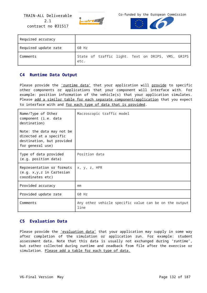
TRAIN-ALL Deliverable 2.1contract no 031517
Co-funded by the European Commission
Decision Support Matrix (DSM)The DecisionSupportMatrix (DSM) specifies the Decision Points and Triggers associated with each COA, or Phase. In MSDL Events don’t have a DSM, but they do have Triggers for the underlying Unit Activities.
Figure 53: the Decision Support Matrix
Each Decision Point (DP) in the DSM includes a DP Name, Description, and free formatted text representing the Commander’s Critical Information Requirements (CCIR). In addition the DP includes a trigger reference. The Trigger is used to “Trigger” the execution of the execution of a Phase, Event, or Unit Activity
TriggersTriggers are used to initiate activities (Phases, Events, and Unit Activities). Phases and Events triggers actually trigger the Decision Point, which leads to the “decision” to initiate the Phase or Event.
There is a hierarchy of trigger scope in MSDL.
V6-Final Version May Page 132 of 140
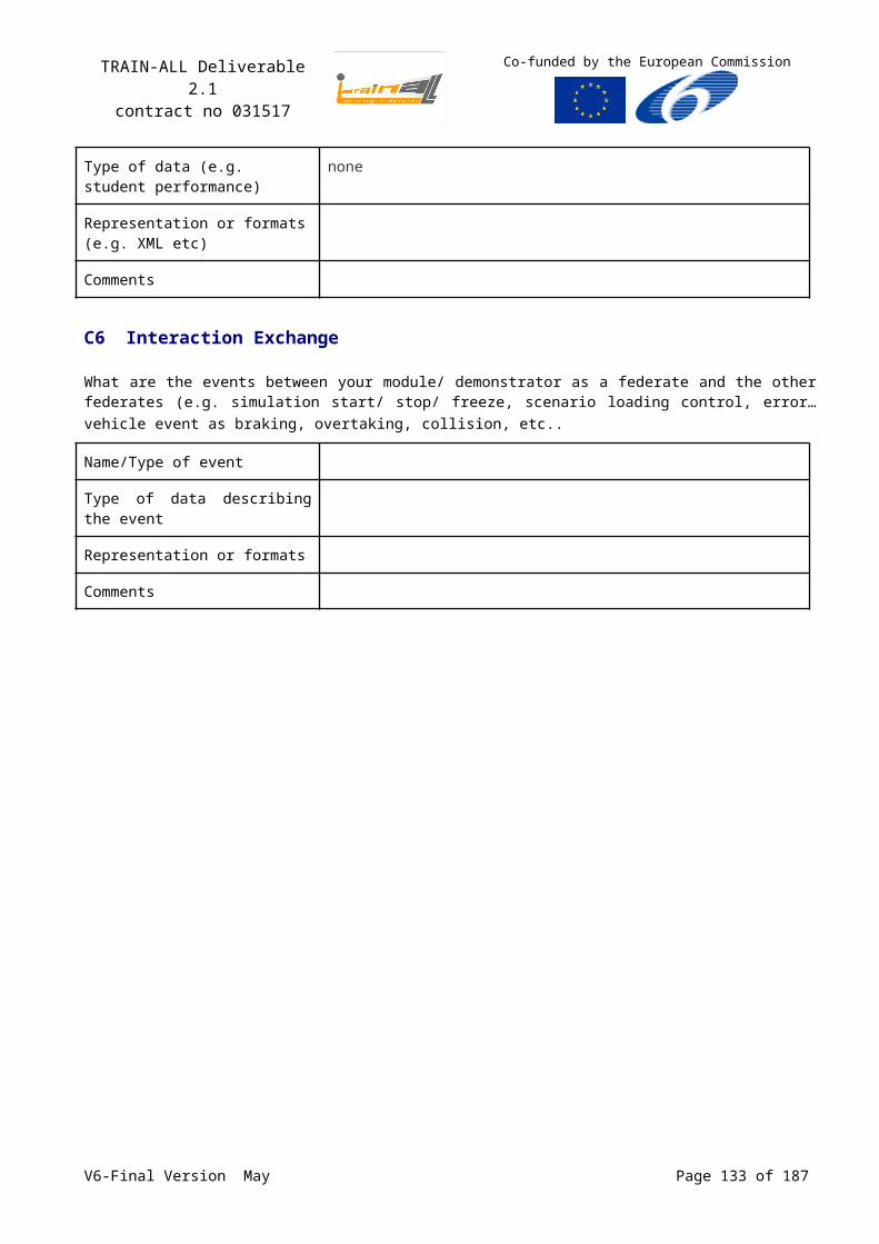
TRAIN-ALL Deliverable 2.1contract no 031517
Co-funded by the European Commission
Figure 54: Trigger
Table 32: Trigger Enumerated ValueMSDL Element Enumerations Description
Trigger Type FRIENDLY_EVENT Specifies the Triggering Event must be a Friendly Event
ENEMY_EVENT Specifies the Triggering Event must be a Enemy Event
THREAT_EVENT Specifies the Triggering Event must be a Threat Event
MOVEMENT_EVENT Specifies the Triggering Event must be a Movement Event
ORDER Specifies the Trigger is to be manually ordered in the simulation.
Time Relation AFTER Specifies the trigger is to occur After the Triggering Event’s point of reference (Action Point of Reference).
BEFORE Specifies the trigger is to occur Before the Triggering Event’s point of reference (Action Point of Reference).
DURING Specifies the trigger is to occur During (at) the Triggering Event’s point of reference (Action Point of Reference).
Action Point of Reference
END Specifies the Time Relation of the Trigger is relative to the End of the Triggering Event.
START Specifies the Time Relation of the Trigger is relative to the Start of the Triggering Event.
V6-Final Version May Page 133 of 140
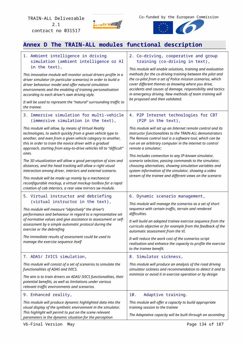
TRAIN-ALL Deliverable 2.1contract no 031517
Co-funded by the European Commission
The Trigger data can be easily interpreted in English as:
Trigger an activity (Phase, COA, Event, Unit Activity) [Relative Time] [Time Relation] [Action Point of Reference] of the Triggering Event. For example:
Trigger “Tactical Road March of A/2-33 AR” DDHHMMSS AFTER START of “Route Reconnaissance of D/1-11 ACR”, where:
“Tactical Road March of A/2-33 AR” is the triggered Unit Activity.
DDHHMMSS is the Relative Time offset in days, hours, minutes, and seconds.
AFTER is the Time Relation.
START is the Action Point of Reference.
“Route Reconnaissance of D/1-11 ACR” is the Triggering Activity.
Trigger Type is FRIENDLY_EVENT.
Triggering activities take on two principle types. Planned activities (Friendly Events and Movement Events) can be used to coordinate and synchronize the military COA. Threat and Enemy Events can be used to trigger responses to those activities. Threat and Enemy Events triggers provide a mechanism for specifying how units should respond to hostile events, which are anticipated as part of the planned COA.
Figure 55: Triggering Event
Friendly and Movement Events represent references to planned actions that are intended to occur as part of the overall planned COA. Threat and Enemy Events represent characterizations of hostile activities.
Triggering Friendly Events provide a means for planning how to synchronize unit actions (Phases, Events, and Unit Activities), relative to when actions start and stop.
V6-Final Version May Page 134 of 140

TRAIN-ALL Deliverable 2.1contract no 031517
Co-funded by the European Commission
Figure 56: Friendly (Triggering) Event
Friendly Event Triggers specify the Action Type to trigger on (COA, Phase, Event, or Activity). There is a scope that applies to these references:
The superior COA, or another Phase in the superior COA can trigger a Phase.
The superior Phase, or another Event in the superior Phase can trigger an Event.
The superior Event, or anther Unit Activity in the superior Event can trigger a Unit Activity.
Note: A Unit Activity can be a subordinate COA; therefore an adjacent Unit Activity, or a higher echelon’s COA Event can trigger a subordinate COA.
Triggering Threat Events provide a means for planning how units will react to MOOTW and METOC events on the battlefield.
Figure 57: Threat (Triggering) Event
Triggering Threat Events identify the named area of interest in which the threat activity is anticipated. It also references the Threat and the Threat Activity their respective Object Handles.
Triggering Enemy Events provide a means for planning how units will react to OPFOR activities on the battlefield.
V6-Final Version May Page 135 of 140
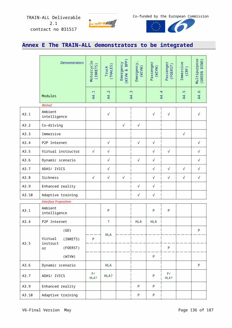
TRAIN-ALL Deliverable 2.1contract no 031517
Co-funded by the European Commission
Figure 58: Enemy (Triggering) Event
Triggering Enemy Events identify the named area of interest in which the enemy activity is anticipated. It also specifies the Echelon (size) of the enemy, Unit Type (Unit Enumeration), and Enemy Activity Type.
Table 33: Enemy Activity TypeMSDL Element Enumerations Description
The enemy is Trigger Type
NOT_SPECIFIED No activity type is specified
ATTACKING The enemy is attacking.
DEFENDING The enemy is defending.
ENGAGING The enemy is engaging.
WITHDRAWING The enemy is withdrawing
DELAYING The enemy is delaying
OBSERVING The enemy is observing
BYPASSING The enemy is bypassing
FORTIFYING The enemy is fortifying
CROSSING_LINE_OF_DEPARTURE The enemy is crossing the line of departure
SCREENING The enemy is screening
MOVING The enemy is moving
GUARDING The enemy is guarding
COVERING The enemy is covering
RECONNOITERING The enemy is reconnoitering
REPAIRING The enemy is conducting repairs
SECURING The enemy is securing an area
ADJUSTING The enemy is adjusting
EVACUATING The enemy is evacuating
INTERROGATING The enemy is interrogating
DISPLACING The enemy is displacing
STATIONARY The enemy is stationary
ASSEMBLING The enemy is assembling
V6-Final Version May Page 136 of 140
TRAIN-ALL Deliverable 2.1contract no 031517
Co-funded by the European Commission
MSDL Element Enumerations Description
MINE_CLEARING The enemy is clearing mines
MINE_LAYING The enemy is laying mines
REFUELING The enemy is refueling
BOMBING The enemy is bombing
ELECTRONIC_WARFARE The enemy is conducting electronic warfare
RIVER_CROSSING The enemy is conducting river crossing activities
HOVERING The enemy is hovering
ORBITING The enemy is orbiting
CHAFF_LAYING The enemy is laying chaff
TRANSITING The enemy is transiting
ACQUIRING_TRACKING The enemy is acquiring and/or tracking
Triggering Movement Events provide a means for planning how to synchronize unit actions (Phases, Events, and Unit Activities), based on the relative location of a unit to known/planned locations (tactical graphics).
Figure 59: Movement (Triggering) Event
Triggering Movement Events identify the moving unit, Tactical Graphic, location of the unit relative to the graphic (Location Point of Reference), and relative distance of the unit to the graphic.
Table 34: Location Point of ReferenceMSDL Element Enumerations Description
Location Point of Reference
APPROACHING Indicates the specified unit is approaching the tactical graphic. The first element of the unit has reached the Relative Distance to the tactical graphic (relative distance is decreasing)
CROSSING Indicates the specified unit is crossing the tactical graphic. The first element of the unit is within the Relative Distance, having already crossed the tactical graphic (relative distance is increasing)
LEAVING Indicates the specified unit is leaving the tactical graphic. The last element of the unit is moving away from and is within the Relative Distance to the tactical graphic (relative distance is increasing)
V6-Final Version May Page 137 of 140
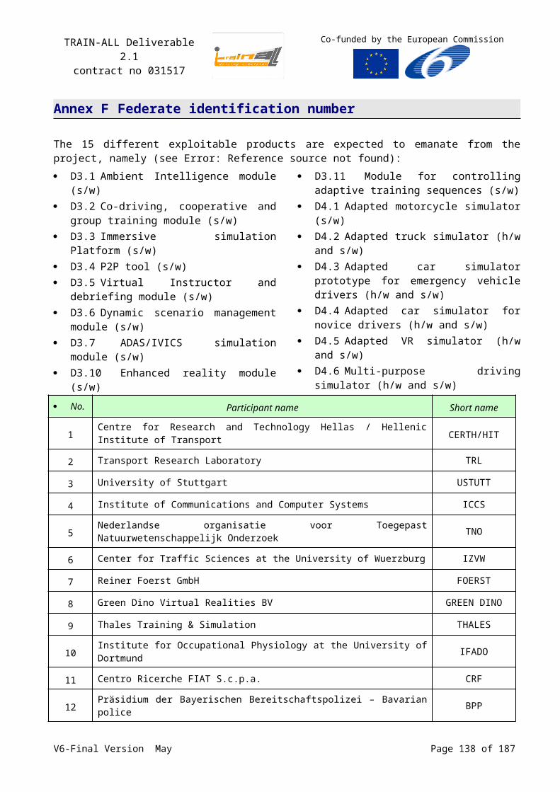
TRAIN-ALL Deliverable 2.1contract no 031517
Co-funded by the European Commission
MSDL Element Enumerations Description
ENTERING Indicates the specified unit is entering the tactical graphic. The first element of a unit is within the Relative Distance to entering an area (relative distance is decreasing)
EXITING Indicates the specified unit is exiting the tactical graphic. The last element of the unit is within the Relative Distance to exiting an area (relative distance is decreasing)
COA phasesCOA Phases are used to specify phases of execution across a Course Of Action.
Figure 60: COA phases
The Phase Sequence specifies the order of phases in the COA. Name is the name applied to the Phase. Decision Point Handle represents the triggering information (decision) leading the execution of a Phase. This handle is a reference to a Decision Point that has been specified as part of the DSM of the Phase’s COA.
V6-Final Version May Page 138 of 140
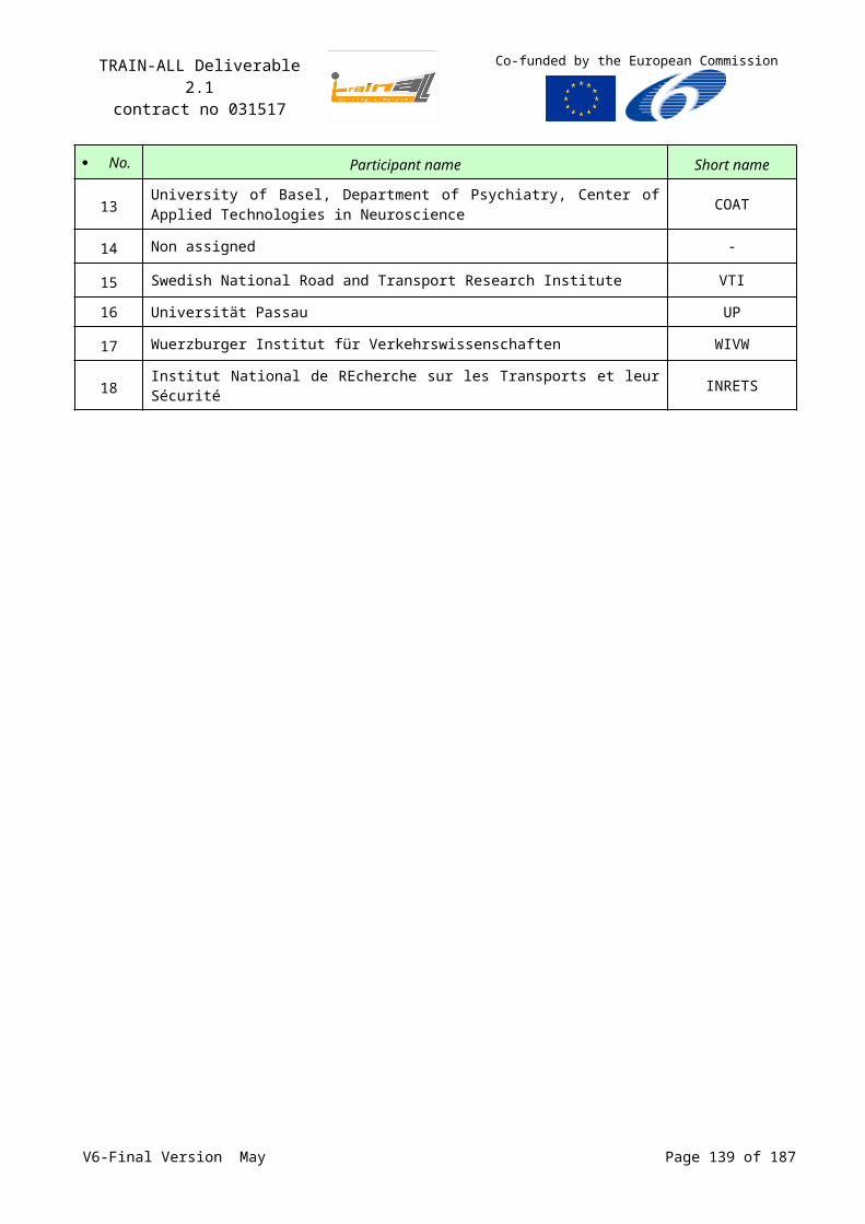
TRAIN-ALL Deliverable 2.1contract no 031517
Co-funded by the European Commission
Phase eventsPhase Events represent the planned or anticipated events that occur during the execution of a Phase.
Figure 61: Events
Unit ActivitiesUnit Activities represent the planned tasks to be executed by subordinate elements of a (superior/command) unit’s Course of Action.
Figure 62: Unit activities
V6-Final Version May Page 139 of 140
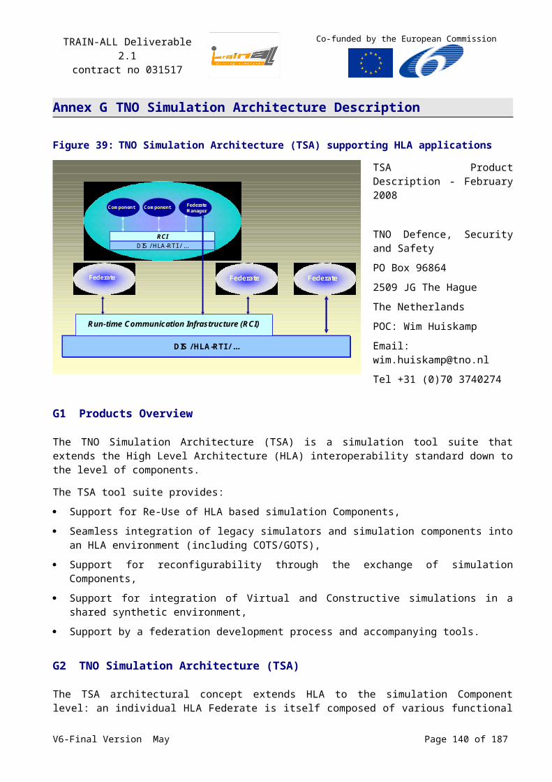
TRAIN-ALL Deliverable 2.1contract no 031517
Co-funded by the European Commission
Event Threat ActivitiesEvent Threat Activities provide mechanism of specifying those Threat events that are anticipated to occur during the execution of an Event.
Figure 63: Event Threat Activity
V6-Final Version May Page 140 of 140