Embed Size (px)
Citation preview
OpenREPORT 1(64)
Uppgjord (även faktaansvarig om annan) - Prepared (also subject responsible if other) Nr - No.
Martin van der Zee (EMN) / Rachid Ait Yaiz (UT) 2/0362-FCPNB 102 88 UenDokansv/Godk - Doc respons/Approved Kontr - Checked Datum - Date Rev File
EMN/K/A Geert Heijenk (5430) 1999-07-09 B
Quality of Service over Specific Link Layers
State of the Art Report
Summary
The Integrated Services concept is proposed as an enhancement to the current Internet architecture, toprovide a better Quality of Service (QoS) than that provided by the traditional Best-Effort service. Thefeatures of the Integrated Services are explained in this report. To support Integrated Services, certainrequirements are posed on the underlying link layer. These requirements are studied by the IntegratedServices over Specific Link Layers (ISSLL) IETF working group. The status of this ongoing research isreported in this document. To be more specific, the solutions to provide Integrated Services over ATM,IEEE 802 LAN technologies and low-bitrate links are evaluated in detail. The ISSLL working group hasnot yet studied the requirements, that are posed on the underlying link layer, when this link layer iswireless. Therefore, this state of the art report is extended with an identification of the requirements thatare posed on the underlying wireless link, to provide differentiated Quality of Service.

OpenREPORT 2(64)
Uppgjord (även faktaansvarig om annan) - Prepared (also subject responsible if other) Nr - No.
Martin van der Zee (EMN) / Rachid Ait Yaiz (UT) 2/0362-FCPNB 102 88 UenDokansv/Godk - Doc respons/Approved Kontr - Checked Datum - Date Rev File
EMN/K/A Geert Heijenk (5430) 1999-07-09 B
Contents
1 ABBREVIATIONS......................................................................................................................................... 4
2 INTRODUCTION........................................................................................................................................... 6
3 INTEGRATED SERVICES ............................................................................................................................ 7
3.1 INTRODUCTION ............................................................................................................................................ 73.2 RESOURCE RESERVATION............................................................................................................................. 73.3 RSVP MESSAGES...................................................................................................................................... 113.4 GUARANTEED SERVICE .............................................................................................................................. 143.5 CONTROLLED-LOAD SERVICE...................................................................................................................... 163.6 LIMITATIONS OF INTEGRATED SERVICES ....................................................................................................... 16
4 INTEGRATED SERVICES OVER SPECIFIC LINK LAYERS ...................................................................... 18
4.1 INTRODUCTION .......................................................................................................................................... 184.2 ATM ........................................................................................................................................................ 18
4.2.1 Introduction...................................................................................................................................... 184.2.2 ATM QoS architecture...................................................................................................................... 19
4.2.2.1 ATM services..........................................................................................................................................194.2.2.2 Traffic parameters...................................................................................................................................214.2.2.3 QoS parameters .....................................................................................................................................224.2.2.4 ATM traffic and congestion control...........................................................................................................24
4.2.3 Mapping of Integrated Services to ATM services.............................................................................. 284.2.3.1 Guaranteed Service ................................................................................................................................294.2.3.2 Controlled-Load Service ..........................................................................................................................294.2.3.3 Best Effort...............................................................................................................................................30
4.2.4 VC management.............................................................................................................................. 304.2.5 Conclusions ..................................................................................................................................... 33
4.3 IEEE 802 LAN TECHNOLOGIES.................................................................................................................. 334.3.1 Introduction...................................................................................................................................... 334.3.2 Frame Forwarding in IEEE 802 Networks......................................................................................... 34
4.3.2.1 Ethernet/IEEE 802.3 ...............................................................................................................................344.3.2.2 Token Ring/IEEE 802.5...........................................................................................................................354.3.2.3 Fiber Distributed Data Interface (FDDI)....................................................................................................354.3.2.4 Demand Priority/IEEE 802.12..................................................................................................................354.3.2.5 Characteristics of different IEEE 802 networks.........................................................................................36
4.3.3 The Bandwidth Manager .................................................................................................................. 364.3.3.1 Requester Module...................................................................................................................................374.3.3.2 Bandwidth Allocator ................................................................................................................................374.3.3.3 Communication Protocols........................................................................................................................37
4.3.4 Centralised versus distributed implementations of the Bandwidth Manager ...................................... 38

OpenREPORT 3(64)
Uppgjord (även faktaansvarig om annan) - Prepared (also subject responsible if other) Nr - No.
Martin van der Zee (EMN) / Rachid Ait Yaiz (UT) 2/0362-FCPNB 102 88 UenDokansv/Godk - Doc respons/Approved Kontr - Checked Datum - Date Rev File
EMN/K/A Geert Heijenk (5430) 1999-07-09 B
4.3.4.1 Centralised Bandwidth Allocator ..............................................................................................................384.3.4.2 Distributed Bandwidth Allocator ...............................................................................................................39
4.3.5 Model of the Bandwidth Manager in a Network................................................................................. 394.3.5.1 End Station Model...................................................................................................................................394.3.5.2 Switch Model ..........................................................................................................................................42
4.3.6 Int-serv Mappings on IEEE 802........................................................................................................ 444.4 LOW-BITRATE LINKS ................................................................................................................................... 45
5 WIRELESS ACCESS TECHNOLOGY REQUIREMENTS ........................................................................... 46
5.1 INTRODUCTION .......................................................................................................................................... 465.2 MULTI-PROTOCOL LABEL SWITCHING .......................................................................................................... 465.3 DIFFERENTIATED SERVICES ........................................................................................................................ 475.4 INTEGRATED SERVICES .............................................................................................................................. 48
5.4.1 General requirements ...................................................................................................................... 485.4.2 Detailed requirements ...................................................................................................................... 48
5.4.2.1 Resource Reservation.............................................................................................................................495.4.2.2 Admission Control...................................................................................................................................495.4.2.3 Flow Separation and Scheduling .............................................................................................................505.4.2.4 Policing and shaping ...............................................................................................................................505.4.2.5 Soft State................................................................................................................................................515.4.2.6 Scalability ...............................................................................................................................................515.4.2.7 Fault Tolerance and Recovery.................................................................................................................515.4.2.8 Independence from Higher Layer Protocol ...............................................................................................515.4.2.9 Receiver Heterogeneity...........................................................................................................................525.4.2.10 Support for different Filter Styles..............................................................................................................52
6 CONCLUSIONS.......................................................................................................................................... 53
6.1 BY ALPHABET ............................................................................................................................................ 546.2 BY CATEGORY ........................................................................................................................................... 58
6.2.1 Internet Drafts.................................................................................................................................. 586.2.2 RFCs ............................................................................................................................................... 586.2.3 ATM forum....................................................................................................................................... 596.2.4 ITU .................................................................................................................................................. 596.2.5 Reports, articles and books.............................................................................................................. 60
7 APPENDIX A PATENTS............................................................................................................................. 61
7.1 INTRODUCTION .......................................................................................................................................... 617.2 SEARCH RESULTS ...................................................................................................................................... 61

OpenREPORT 4(64)
Uppgjord (även faktaansvarig om annan) - Prepared (also subject responsible if other) Nr - No.
Martin van der Zee (EMN) / Rachid Ait Yaiz (UT) 2/0362-FCPNB 102 88 UenDokansv/Godk - Doc respons/Approved Kontr - Checked Datum - Date Rev File
EMN/K/A Geert Heijenk (5430) 1999-07-09 B
1 Abbreviations
ABR Available BitRate
AC Admission Control
AF Assured Forwarding
BA Bandwidth Allocation
BB Bandwidth Broker
BE Best Effort
BM Bandwidth Manager
CAC Call Admission Control
CB Class Based
CBR Constant BitRate
CDVT Cell Delay Variation Tolerance
CER Cell Error Ratio
CLR Cell Loss Ratio
CMR Cell Mis-insertion Rate
CTD Cell Transfer Delay
DS Differentiated Services
DSBM Designated Subnet Bandwidth Manager
EF Expedited Forwarding
EFCI Explicit Forward Congestion Indication
FDDI Fiber Distributed Data Interface
FF Fixed Filter
FRM Fast Resource Management
GCRA Generic Cell Rate Algorithm
GS Guaranteed Service
IETF Internet Engineering Task Force
IS Integrated Services
ISSLL Integrated Services over Specific Link Layers
LANE LAN Emulation
LDP Label Distribution Protocol
LER Label Edge Node
LIB Label Information Base
LIS Logical IP Subnet
LIJ Leaf Initiated Join
LSP Label Switched Path
LSR Label Switching Node
MARS Multicast Address Resolution Server
MBS Maximum Burst Size

OpenREPORT 5(64)
Uppgjord (även faktaansvarig om annan) - Prepared (also subject responsible if other) Nr - No.
Martin van der Zee (EMN) / Rachid Ait Yaiz (UT) 2/0362-FCPNB 102 88 UenDokansv/Godk - Doc respons/Approved Kontr - Checked Datum - Date Rev File
EMN/K/A Geert Heijenk (5430) 1999-07-09 B
MCR Minimum Cell Rate
MPLS Multi-Protocol Label Switching
MPOA Multi-Protocol Over ATM
MTU Maximum Transmission Unit
NHLFE Next Hop Label Forwarding Entry
NMS Network Management System
NNI Network Network Interface
NPC Network Parameter Control
nrt-VBR non real-time Variable BitRate
OPWA One Pass With Advertising
OSPF Open Shortest Path First
PC Policy Control
PHB Per-Hop-Behavior
PHOP Previous HOP
PNNI Private Network Network Interface
PPP Point-to-Point Protocol
PT Payload Type
PVC Permanent Virtual Connection
QoS Quality of Service
RSVP Resource reSerVation Protocol
RM Requester Module
rt-VBR real-time Variable BitRate
SBM Subnet Bandwidth Manager
SCR Sustained Cell Rate
SE Shared Explicit
SECBR Severely Errored Cell Block Ratio
SLA Service Level Agreement
SNMP Simple Network Management Protocol
ST2 Internet Stream Protocol Version 2
SVC Switched Virtual Connection
TTL Time To Live
UBR Unspecified BitRate
UNI User Network Interface
UPC Usage Parameter Control
VC Virtual Connection
VPN Virtual Private Network
WF Wildcard Filter
WFQ Weighted Fair Queueing
WRED Weighted Random Early Detection
OpenREPORT 6(64)
Uppgjord (även faktaansvarig om annan) - Prepared (also subject responsible if other) Nr - No.
Martin van der Zee (EMN) / Rachid Ait Yaiz (UT) 2/0362-FCPNB 102 88 UenDokansv/Godk - Doc respons/Approved Kontr - Checked Datum - Date Rev File
EMN/K/A Geert Heijenk (5430) 1999-07-09 B
2 Introduction
The Integrated Services concept is proposed as an enhancement to the current Internet architecture, toprovide a better Quality of Service (QoS) than that provided by the traditional Best-Effort service. TheIntegrated Service (IS) architecture defines new services offered at the network layer. Currently two ISservices are defined: Guaranteed Service and Controlled-Load Service. To support Integrated Services,certain requirements are posed on the underlying link layer. These requirements are studied by theIntegrated Services over Specific Link Layers (ISSLL) IETF working group.
This report gives an overview of the status of ongoing research to provide Integrated Services in theInternet. First the Integrated Services features are explained in Chapter 3. Next the status of the work ofthe ISSLL working group is reported in Chapter 2. The solutions to provide Integrated Services overATM, IEEE 802 LAN technologies and low-bitrate links are evaluated in detail.
The ISSLL working group has not yet studied the requirements that are posed on the underlying linklayer, when this link layer is wireless. Therefore this state of the art report is extended with anidentification of the requirements that are posed on the underlying wireless link, to provide differentiatedQuality of Service. These requirements are presented in Chapter 5. The requirements are not limited tothe Integrated Services point of view. Other approaches to provide differentiated services are taken intoaccount, such as Differentiated Services and the Multi-Protocol Label Switching.
It is explicitly noted that the solutions presented in this document are not the ideas of the author, butmerely an overview of existing work is presented, appropriate references are provided. In the followingtext it is assumed that the reader is familiar with the TCP/IP protocol suite.

OpenREPORT 7(64)
Uppgjord (även faktaansvarig om annan) - Prepared (also subject responsible if other) Nr - No.
Martin van der Zee (EMN) / Rachid Ait Yaiz (UT) 2/0362-FCPNB 102 88 UenDokansv/Godk - Doc respons/Approved Kontr - Checked Datum - Date Rev File
EMN/K/A Geert Heijenk (5430) 1999-07-09 B
3 Integrated Services
3.1 Introduction
There are two main purposes for the introduction of Integrated Services (IS) in the Internet. FirstIntegrated Services enables the support of real-time services such as voice and video (as explained inmore detail below). Secondly, the Integrated Service provides control over network resources tooperators, also referred to as controlled link-sharing.
The service traditionally provided by the Internet is often referred to as Best Effort (BE). This servicemakes a reasonable attempt to deliver packets from source to destination, as fast as possible. However,packets may suffer from loss, delay, delay variation (also referred to as jitter), duplication and re-ordering. The traditional BE service does not provide Quality of Service (QoS) guarantees, necessary tosupport emerging new real-time applications. The traditional BE service treats each packet equally, andduring periods of congestion packets may be delayed, dropped or re-ordered. Therefore the Internetservice architecture is extended with an architecture, referred to as 'Integrated Services', that canprovide the QoS requirements of real-time services [RFC1633]. This extended architecture is mainlyconcerned with the one-way packet delay. Real-time applications that employ a play-back buffer requirethe data to arrive before the 'play-back' point. This places certain requirements on the delay variation. Inaddition, interactive real-time applications require a sufficiently low average delay to make them useful.It should be noted that this new architecture is designed from the offset to support multi-castapplications.
To provide a service quality better than BE, resources are reserved within the Internet, which isexplained in Section 3.2. Resource reservation is done with the Resource reSerVation Protocol (RSVP),which is discussed in Section 3.3. The Integrated Service provides two different services: GuaranteedService [RFC2212] and Controlled-Load Service [RFC2211] explained in Sections 3.4 and 3.5respectively. Finally the limitations of the Integrated Services concept are discussed in Section 3.6.
3.2 Resource reservation
To provide a Quality of Service, better than that provided by Best Effort service, resources are explicitlyreserved within the network. This resource reservation is installed in the network through a signallingprotocol. The Resource reSerVation Protocol (RSVP) [RFC2205], [RFC2210], [WHITE97], [ZHANG93]is explicitly designed to fulfil this task, but other signalling protocols could be used as well. The maintask of RSVP is to install ‘Reservation State’ in the intermediate nodes between the end-systems.Traditionally, state information has only to be maintained in the end-systems. This shift poses limitationsto the Integrated Service (IS) concept which are discussed in Section 3.6. To align this resourcereservation better with the connectionless robustness of IP, this state information is maintained throughso-called soft states. With soft state, the state information is periodically refreshed through exchange ofsignalling messages. When these periodic refreshments are not received, the state information isautomatically deleted.
An important unit of IS architecture is a flow. A flow is the unit, for which resources are reserved in thenetwork, and which can be identified uniquely (by the unicast or multicast source and destinationaddress and protocol identifier (port numbers are optional)1). A flow is unidirectional, i.e. to provideduplex QoS communication, resources need to be reserved for each direction separately. Flows are thegranularity for which QoS commitments are provided within the Integrated Service architecture.
1 In case of IPv6 the flow label could be used for classification.

OpenREPORT 8(64)
Uppgjord (även faktaansvarig om annan) - Prepared (also subject responsible if other) Nr - No.
Martin van der Zee (EMN) / Rachid Ait Yaiz (UT) 2/0362-FCPNB 102 88 UenDokansv/Godk - Doc respons/Approved Kontr - Checked Datum - Date Rev File
EMN/K/A Geert Heijenk (5430) 1999-07-09 B
To explain the IS service operation in more detail, an example is depicted in Figure 1. In this examplethere is a source A, which transmits a video signal to receivers B, C and D. In this example IPmulticasting is used to transmit efficiently to a group of receivers. To receive an improved QoS, betterthan BE, a resource reservation is made along the multicast tree (dark lines). It should be noted that theresource reservation is uni-directional. To establish duplex reservations, two separate reservations mustbe made.
Figure 1 RSVP example.
The resource reservation is initiated by the periodic transmission of so-called Path messages, by thesource to all receivers. This Path message is routed as any normal IP packet from source to destination.In this case multicast routing is applied. With the Path message, the source identifies itself to thereceivers. The Path message does not contain the actual resource reservation request. The Pathmessage contains a specification of the traffic characteristics of the source, and while travelling fromsource to destination, collects information of the path, which is of interest to the receivers. The receiversuse this information to make an appropriate reservation. Note that Path messages are duplicated atbranch points in the distribution tree2.
Upon receipt of the Path message by the receiver, the receiver may decide to reserve resources for thistraffic flow, based on the information (source traffic and path characteristics) contained in the Pathmessage. The receiver starts transmitting periodically so-called Resv messages towards the source.This Resv message contains the request, to reserve resource along the path towards the source. It isimportant that the Resv message follows the same path as the Path message has, and because routingin the Internet is not necessarily symmetric, normal routing cannot be applied to route the Resvmessage towards the source. To facilitate this requirement, the Path message has installed so-calledreserve path routing state in the intermediate routers, while it travelled toward the receiver. Thisinformation is used to route Resv messages back towards the source.
While the Resv is transmitted from receiver to the source, resources are reserved at the intermediaterouters. Both the Path and the Resv messages need to be transmitted periodically (default every 30seconds) to maintain the Reservation State in the network. The network reservation is installed throughso-called soft-state i.e. when the transmission of either Path or Resv messages is stopped, the resource
2 The Adspec of the outgoing Path messages may be different dependent on the outgoing link characteristics.
Source A
Receiver B
Receiver C
Receiver D
OpenREPORT 9(64)
Uppgjord (även faktaansvarig om annan) - Prepared (also subject responsible if other) Nr - No.
Martin van der Zee (EMN) / Rachid Ait Yaiz (UT) 2/0362-FCPNB 102 88 UenDokansv/Godk - Doc respons/Approved Kontr - Checked Datum - Date Rev File
EMN/K/A Geert Heijenk (5430) 1999-07-09 B
reservation is automatically deleted3. This soft-state provides some of the traditional robustness of theInternet.
When a link fails along the path of the flow, the normal routing protocol will route the Path messagesalong a new path. This will install new reserve routing state for Resv message and eventually a newresource reservation will be made along the new path.
The Integrated Services concept makes use of the existing IP routing functionality in the network. Boththe RSVP signalling messages, and the QoS data follow the same route, as normal BE traffic would.Furthermore the Integrated Services / RSVP works equally well with IPv4 and IPv64.
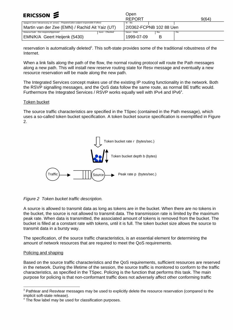
Token bucket
The source traffic characteristics are specified in the TSpec (contained in the Path message), whichuses a so-called token bucket specification. A token bucket source specification is exemplified in Figure2.
Figure 2 Token bucket traffic description.
A source is allowed to transmit data as long as tokens are in the bucket. When there are no tokens inthe bucket, the source is not allowed to transmit data. The transmission rate is limited by the maximumpeak rate. When data is transmitted, the associated amount of tokens is removed from the bucket. Thebucket is filled at a constant rate with tokens, until it is full. The token bucket size allows the source totransmit data in a bursty way.
The specification, of the source traffic characteristics, is an essential element for determining theamount of network resources that are required to meet the QoS requirements.
Policing and shaping
Based on the source traffic characteristics and the QoS requirements, sufficient resources are reservedin the network. During the lifetime of the session, the source traffic is monitored to conform to the trafficcharacteristics, as specified in the TSpec. Policing is the function that performs this task. The mainpurpose for policing is that non-conformant traffic does not adversely affect other conforming traffic
3 Pathtear and Resvtear messages may be used to explicitly delete the resource reservation (compared to theimplicit soft-state release).4 The flow label may be used for classification purposes.
Peak rate p (bytes/sec.)
Token bucket rate r (bytes/sec.)
Token bucket depth b (bytes)
Traffic Source

OpenREPORT 10(64)
Uppgjord (även faktaansvarig om annan) - Prepared (also subject responsible if other) Nr - No.
Martin van der Zee (EMN) / Rachid Ait Yaiz (UT) 2/0362-FCPNB 102 88 UenDokansv/Godk - Doc respons/Approved Kontr - Checked Datum - Date Rev File
EMN/K/A Geert Heijenk (5430) 1999-07-09 B
flows, or normal BE traffic.
When a packet in a flow is found non-conformant the following actions can be taken:
• Discard
• Treat as Best Effort or worse5
• Mark traffic as non-conformant, which enables non-conformant traffic to receive different treatmentat subsequent routers.
Policing should be done at least at the source node, and possibly at other nodes.
Shaping is the function that delays packets of a flow, such that the traffic flow conforms to the TSpec.Reshaping is possibly needed at so-called branch and merge points in the distribution tree, as depictedin Figure 3.
Figure 3 Branch and merge points.
At branch points the reservation on one of the outgoing links may be smaller than the reservation on theincoming link (e.g. low bitrate branch). At merge points the sum of the incoming reservations may begreater than the outgoing reservation (e.g. in case of shared reservation styles).
Router architecture
There are four main components, needed to provide 'Integrated Services' within a router: PacketClassifier, Packet Scheduler, Admission Control and Policy Control as depicted in Figure 4.
5 When packets of the same flow are put in different queues, the order of the packets may be affected. Whenpackets are reordered this may have an adverse affect on the performance of higher layer protocols such as TCP.
S1
R
1
R
2
S1
R
1S2
Branch point Merge point

OpenREPORT 11(64)
Uppgjord (även faktaansvarig om annan) - Prepared (also subject responsible if other) Nr - No.
Martin van der Zee (EMN) / Rachid Ait Yaiz (UT) 2/0362-FCPNB 102 88 UenDokansv/Godk - Doc respons/Approved Kontr - Checked Datum - Date Rev File
EMN/K/A Geert Heijenk (5430) 1999-07-09 B
Figure 4 RSVP capable node architecture.
Data plane
The Packet Classifier identifies those packets of the incoming stream, which are elected to receivepreferential treatment. Classification allows the identification of traffic flows. Dependent on theclassification result, the incoming packet is scheduled for a particular treatment carried out by thePacket Scheduler.
The Packet Scheduler actually executes this treatment when managing one or more output queues, totransmit packets on the outgoing interface6. The scheduling technique is vendor dependent. Differentscheduling mechanisms can be selected such as Class Based queueing (CB) [FLOYD95], WeightedFair Queueing (WFQ) [ZHANG95] or Weighted Random Early Detection (WRED) [FLOYD93].
Control plane
The Routing block illustrates the normal routing functionality found in IP routers. This block is notIntegrated Services specific, but is depicted for completeness.
The Policy Control (PC) entity either accepts or rejects the resource request dependent on theimplemented policy. The policy control entity offers the operator the ability to enforce certain constraintson the resource distribution.
The Admission Control (AC) entity either accepts or rejects the resource requests, dependent on theavailable resources. In this way AC provides a means to control the load of QoS flows, which is crucialto provide QoS guarantees.
The RSVP State registers the state information of the RSVP sessions currently active.
3.3 RSVP messages
In this section the Resource reSerVation Protocol (RSVP) messages are discussed in more detail. Thereader who is only interested in an overview may skip this section.
6 It should be noted that large Best Effort packets delay higher priority traffic when no pre-emptive scheduling isapplied.
AdmissionControl
Incoming interface
Packetforwarding path
Path Resv
RSRSRSVPstate
PacketScheduler
PacketClassifier
PolicyControlRouting
Outgoing interface
Control plane
Data plane

OpenREPORT 12(64)
Uppgjord (även faktaansvarig om annan) - Prepared (also subject responsible if other) Nr - No.
Martin van der Zee (EMN) / Rachid Ait Yaiz (UT) 2/0362-FCPNB 102 88 UenDokansv/Godk - Doc respons/Approved Kontr - Checked Datum - Date Rev File
EMN/K/A Geert Heijenk (5430) 1999-07-09 B
The information elements contained in the Path and Resv messages are listed in Table 1.
Path Resv
Source traffic characteristics (TSpec) Reservation specification (RSpec)
Sender template Reservation style
End-to-end path characteristics (Adspec) Filterspec7 (= Sender template)
IP address of the previous RSVP-capable node (PHOP) TSpec
ResvConf
Service Class
Table 1 Resv and Path message elements.
The sender template is also referred to as filterspec. The sender template is used to classify incomingpackets to a router. The sender template contains the sender IP address and the sender port number.
Reverse routing state is installed in the network, while the Path message travels from source todestination. This information is carried in the PHOP element of the Path message.
The reservation styles refer to the way in which the RSVP resources are shared among multiple sourceswithin a single RSVP session:
• Fixed Filter (FF): there is a single source associated with the resource reservation.
• Shared Explicit (SE): there are multiple sources, explicitly identified, which may use the resourcereservation.
• Wildcard Filter (WF): any source of the RSVP session may use the resource reservation.
Dependent on the reservation filter selected, the incoming Resv messages are merged and transmittedto upstream nodes in the distribution tree. For further detail see [WHITE97].
An RSVP session is defined by the destination triple: destination address, transport layer protocol typeand optional a port number [RFC2205]. Each RSVP message (e.g. Path and Resv) includes anidentification to which RSVP session it applies. An RSVP session may consist of multiple traffic flows,i.e. end-to-end application traffic. Note that there is only one source per flow.
A Resv message also contains a TSpec, which generally equals the TSpec specified by the source.However, the Maximum datagram size MReceiver is set to min(MSender, pathMTU). Furthermore the TSpecof the receiver may be smaller than the TSpec of the source to support receiver heterogeneity i.e. areceiver may decide to receive only part of the source traffic stream e.g. low quality service.
Acknowledgement of a resource reservation request can be requested by the ResvConf element. Thenode accepting the reservation request, at which the propagation of the Resv message ends up the
7 Omitted in case of Wild Card reservation filter.

OpenREPORT 13(64)
Uppgjord (även faktaansvarig om annan) - Prepared (also subject responsible if other) Nr - No.
Martin van der Zee (EMN) / Rachid Ait Yaiz (UT) 2/0362-FCPNB 102 88 UenDokansv/Godk - Doc respons/Approved Kontr - Checked Datum - Date Rev File
EMN/K/A Geert Heijenk (5430) 1999-07-09 B
distribution tree, should return a ResvConf message to the receiver.
The type of service requested is indicated by the Service Class. Two types of services are defined untilnow: Guaranteed Service and Controlled-Load Service.
The TSpec, RSpec and Service Class, contained in the Resv message, is also referred to as Flowspec.
It should be noted that both the Path and Resv message might carry additional objects. Two importantobjects are mentioned here. The Policy object may be used to distribute the policy information and theIntegrity object may be used to carry security information.
The traffic parameters of the TSpec are listed in Table 2.
TSpec Denoted as Unit
Peak rate p bytes/sec.
Bucket depth b bytes
Token bucket rate r bytes/sec.
Minimum policed unit m bytes
Maximum datagram size M bytes
Table 2 TSpec parameters.
The parameters of the RSpec are listed in Table 3.
RSpec Denoted as Unit
Bandwidth R bytes/sec.
Slack term S milliseconds
Table 3 RSpec parameters.
The RSpec is used for the Guaranteed Service only. The Controlled-Load service Resv message doesnot contain an RSpec. The Resv messages contains a Bandwidth R and a Slack term S. The Bandwidthrequirement R specifies the amount of resources needed. The Slack term S is explained in Section 3.4(see Figure 6). It should be noted that no buffer space requirement is included in the RSpec. Eachnetwork element is expected to derive the required buffer space, to ensure no queueing loss, from theTSpec, the RSpec, the Adspec, combined with internal information about how the element manages itstraffic.
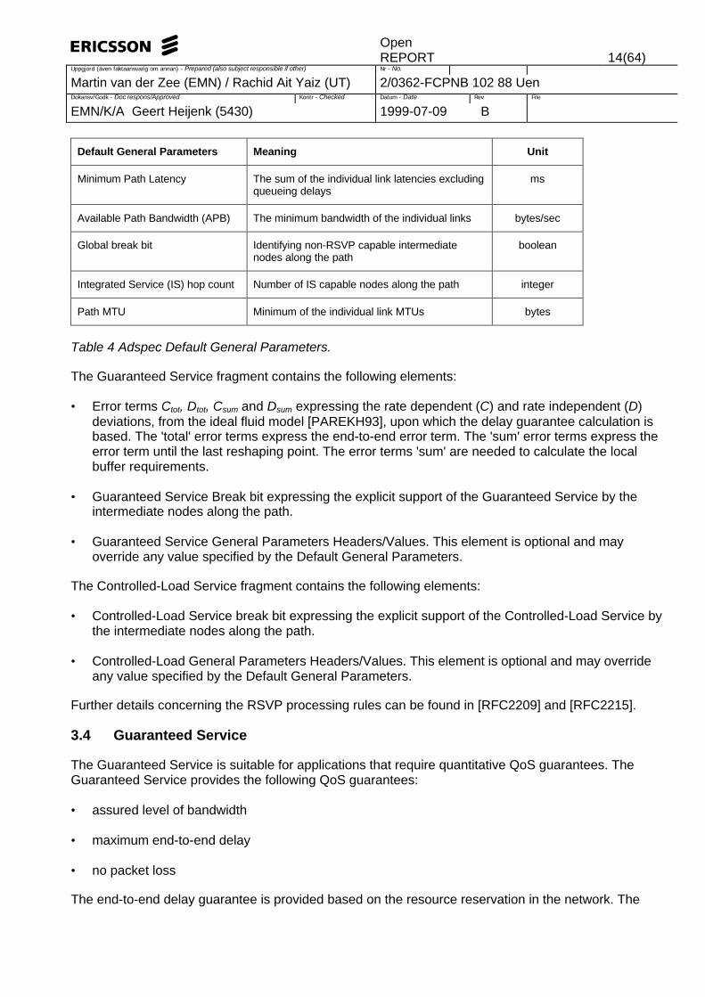
The end-to-end path characteristics are listed in the Adspec. The Adspec contains a Default GeneralParameters element and a Guaranteed or Controlled-Load service fragment. The elements contained inthe Default General Parameters are listed in Table 4.
OpenREPORT 14(64)
Uppgjord (även faktaansvarig om annan) - Prepared (also subject responsible if other) Nr - No.
Martin van der Zee (EMN) / Rachid Ait Yaiz (UT) 2/0362-FCPNB 102 88 UenDokansv/Godk - Doc respons/Approved Kontr - Checked Datum - Date Rev File
EMN/K/A Geert Heijenk (5430) 1999-07-09 B
Default General Parameters Meaning Unit
Minimum Path Latency The sum of the individual link latencies excludingqueueing delays
ms
Available Path Bandwidth (APB) The minimum bandwidth of the individual links bytes/sec
Global break bit Identifying non-RSVP capable intermediatenodes along the path
boolean
Integrated Service (IS) hop count Number of IS capable nodes along the path integer
Path MTU Minimum of the individual link MTUs bytes
Table 4 Adspec Default General Parameters.
The Guaranteed Service fragment contains the following elements:
• Error terms Ctot, Dtot, Csum and Dsum expressing the rate dependent (C) and rate independent (D)deviations, from the ideal fluid model [PAREKH93], upon which the delay guarantee calculation isbased. The 'total' error terms express the end-to-end error term. The 'sum' error terms express theerror term until the last reshaping point. The error terms 'sum' are needed to calculate the localbuffer requirements.
• Guaranteed Service Break bit expressing the explicit support of the Guaranteed Service by theintermediate nodes along the path.
• Guaranteed Service General Parameters Headers/Values. This element is optional and mayoverride any value specified by the Default General Parameters.
The Controlled-Load Service fragment contains the following elements:
• Controlled-Load Service break bit expressing the explicit support of the Controlled-Load Service bythe intermediate nodes along the path.
• Controlled-Load General Parameters Headers/Values. This element is optional and may overrideany value specified by the Default General Parameters.
Further details concerning the RSVP processing rules can be found in [RFC2209] and [RFC2215].
3.4 Guaranteed Service
The Guaranteed Service is suitable for applications that require quantitative QoS guarantees. TheGuaranteed Service provides the following QoS guarantees:
• assured level of bandwidth
• maximum end-to-end delay
• no packet loss
The end-to-end delay guarantee is provided based on the resource reservation in the network. The

OpenREPORT 15(64)
Uppgjord (även faktaansvarig om annan) - Prepared (also subject responsible if other) Nr - No.
Martin van der Zee (EMN) / Rachid Ait Yaiz (UT) 2/0362-FCPNB 102 88 UenDokansv/Godk - Doc respons/Approved Kontr - Checked Datum - Date Rev File
EMN/K/A Geert Heijenk (5430) 1999-07-09 B
required bandwidth is based on a (perfect) fluid model. The receiver computes the bandwidth R, to bereserved, based on the delay requirement D (e.g. specified by the receivers application) and theinformation received in the TSpec (r, b, p, min(M, pathMTU)) and Adspec (minimum path latency,available path bandwidth, Ctot, Dtot), as depicted in Figure 5.
Figure 5 Bandwidth reservation for Guaranteed Service.
First the minimum path latency is subtracted from the required delay D. Next the required bandwidth iscomputed based on the ideal fluid model. According to the fluid model and taking into account thedeviations from this ideal model (Ctot, Dtot and M), the relation between delay D and the bandwidth R isgiven by [RFC2212]:
≥≥++
≥>++
+−
−−
=rpRD
R)CM(
rRpDR
)CM()rp(R
)Rp)(Mb(
D
tottot
tottot
(1)
The required bandwidth R is not allowed to exceed the available path bandwidth specified in theAdspec.
The resource reservation request is specified in both a bandwidth R (bytes/sec.) and a slack term S(msec.). The slack term allows a router to provide less resource than the specified bandwidth, while thedelay requirements are still met. This is exemplified in Figure 6.
Figure 6 Slack term example.
Source
Source
Receiver
Receiver
5 Mb/s 3 Mb/s 6 Mb/s
5 Mb/s 3 Mb/s 6 Mb/s
Resource RequestR = 4 Mb/sS = 0 msec.
Resource RequestR = 5 Mb/sS = 100 msec.
ReceiverAdspec
TspecDelay requirement D e.g. < 100 ms.
Rspec (Bandwidth e.g. 2 Mbps)

OpenREPORT 16(64)
Uppgjord (även faktaansvarig om annan) - Prepared (also subject responsible if other) Nr - No.
Martin van der Zee (EMN) / Rachid Ait Yaiz (UT) 2/0362-FCPNB 102 88 UenDokansv/Godk - Doc respons/Approved Kontr - Checked Datum - Date Rev File
EMN/K/A Geert Heijenk (5430) 1999-07-09 B
In Figure 6, the middle router is not able to provide the 4 Mb/sec. bandwidth. Therefore the initialresource request, with slack term zero, is rejected. However, the middle router is able to provide 3 Mb/s,provided that there is enough slack, to meet the end-to-end delay requirement. The middle routerreduces the slack term appropriately before it transmits the Resv message upstream to the source.
It is possible that there are some non-RSVP capable routers in the end-to-end path, as depicted inFigure 7.
Figure 7 Non-RSVP cloud example.
The RSVP Path and Resv messages are transparently transferred across this cloud. However, no QoSguarantees can be provided when the end-to-end path is hit by a non-RSVP capable cloud. Theexistence of non-RSVP capable routers along the path is indicated by the global break bit.
3.5 Controlled-Load Service
The Controlled-Load Service is suitable to support adaptive real-time applications. These applicationsdo not require the stringent QoS guarantees, as provided by the Guaranteed Service, but are tolerant toa limited amount of QoS degradation. The Controlled-Load Service does not provide explicit QoSguarantees, but aims to provide QoS as experienced by a Best-Effort service in a lightly loaded network.No explicit resources are reserved within the network, as with the Guaranteed Service.
3.6 Limitations of Integrated Services
Currently there are many router vendors that provide Integrated Services support. However, there aresevere limitations to this architecture, which make the future of it uncertain. These limitations arediscussed in [RFC2208].
The most important limitation is the scalability of the Integrated Services concept. In networks with ahigh number of RSVP flows, the state information stored, at the intermediate routers, gets large.Especially deployment of high-speed links, with many small RSVP reservations, may be very processingand storage consuming. Furthermore packet classification and scheduling may add additionalperformance penalties concerning router performance. Therefore it is not recommended to implement ISservice capabilities in the high-speed backbone Internet [RFC2208].
Another limitation may arise from the absence of a key infrastructure that is needed to protect against
Source
Receiver
Receiver
Receiver
Non-RSVP cloud

OpenREPORT 17(64)
Uppgjord (även faktaansvarig om annan) - Prepared (also subject responsible if other) Nr - No.
Martin van der Zee (EMN) / Rachid Ait Yaiz (UT) 2/0362-FCPNB 102 88 UenDokansv/Godk - Doc respons/Approved Kontr - Checked Datum - Date Rev File
EMN/K/A Geert Heijenk (5430) 1999-07-09 B
denial of service attacks. RSVP hop-by-hop authentication can protect against denial of service, butrequires the distribution of keys to be used by the MD5 checksum, carried in the Integrity Object. Notonly RSVP may benefit from a key infrastructure, but also the security of IP routing (e.g. Mobile IP) isimproved substantially with a general key infrastructure deployment.
The RSVP protocol allows the transmission of Policy Objects to distribute policy information. However,the content of these objects is not specified i.e. the actual policy is vendor dependent. Care should betaken when assuming that a consistent policy is implemented among different vendors.
The Integrated Services concept poses serious requirements on routers such as to implement multi-fieldpacket classification, admission control, packet scheduling and RSVP signalling processing. Theseenhancements come with a cost in router complexity, throughput and storage requirements.

OpenREPORT 18(64)
Uppgjord (även faktaansvarig om annan) - Prepared (also subject responsible if other) Nr - No.
Martin van der Zee (EMN) / Rachid Ait Yaiz (UT) 2/0362-FCPNB 102 88 UenDokansv/Godk - Doc respons/Approved Kontr - Checked Datum - Date Rev File
EMN/K/A Geert Heijenk (5430) 1999-07-09 B
4 Integrated Services over Specific Link Layers
4.1 Introduction
The Integrated Services (IS) architecture enhances the Internet architecture to support real-timeservices. In the end-to-end path, between the IS hosts, different layer 2 technologies may be used. TheIntegrated Service over Specific Link Layers (ISSLL) Working Group of the Internet Engineering TaskForce (IETF) specifies protocols and defines architectures, needed to support Integrated Servicecapabilities over specific layer 2 technologies. In this chapter an overview of the current research in thisarea is provided.
First the issues to provide Integrated Services over ATM are evaluated in Section 4.2. It is assumed thatthe reader is familiar with ATM. Next the solution to support Integrated Services in IEEE 802-stylenetworks, such as Ethernet, FDDI and token ring, is presented in Section 4.2.5. Finally slow speed linkare discussed briefly in Section 4.4.
4.2 ATM
4.2.1 Introduction
An example of an end-to-end RSVP connection, which uses an intermediate ATM network, is depictedin Figure 8.
Figure 8 Layer 2 configurations.
The ATM technology provides the ability to establish point-to-point and point-to-multipoint VirtualConnections (VC) with a specified QoS. The Integrated Service architecture provides the ability toenhance the traditional Best Effort (BE) service with QoS services. An obvious approach is to evaluatehow the ATM QoS capabilities can be used to provide Integrated Services. To provide somebackground information, the traditional IP over ATM solutions are briefly discussed next.
Part of the problem to provide Integrated Service over an ATM network has been solved with 'ClassicalIP over ATM' [RFC2225], which provides a solution to run IP Best Effort service over an ATM sublayer.For this purpose a Logical IP Subnet (LIS) is defined. A LIS is a group of IP hosts sharing a common IPsubnet address and who communicate with each other directly using ATM connections. Communicationbetween hosts on different LISs must traverse at least one IP router. The classical IP over ATM modellimits ATM to intra-subnet connectivity. The ATM forum has provided similar methods to provide IP overATM with the Multi-Protocol Over ATM (MPOA) [AF97] and LAN Emulation (LANE) [AF95].
Application
Ethernet
PHY
Ethernet
PHY
ATM
PHY
IP (RSVP) IP Router (RSVP)
PHY
ATM
PHY
Application
PPP
PHY
ATM
PHY
PPP
PHY
IP (RSVP)IP Router (RSVP)
Host IP router/ATM ingress ATM node IP Router/ATM egress host

OpenREPORT 19(64)
Uppgjord (även faktaansvarig om annan) - Prepared (also subject responsible if other) Nr - No.
Martin van der Zee (EMN) / Rachid Ait Yaiz (UT) 2/0362-FCPNB 102 88 UenDokansv/Godk - Doc respons/Approved Kontr - Checked Datum - Date Rev File
EMN/K/A Geert Heijenk (5430) 1999-07-09 B
The IP to ATM address resolution is performed by the ATMARP service. Each host is configured withthe ATM address of the ATMARP server of that LIS. Each host on the LIS registers with the ATMARPserver, by associating its IP address with an ATM address.
Furthermore the IP multicast over ATM has been solved with the Multicast Address Resolution Server(MARS) [RFC2022], which allows the resolution of an IP group address into a list of ATM addressesconstituting the group members. Normally the root of the multi-cast tree is responsible for setting up newbranches and removing branches. This poses a severe burden on the root processing capacity. With theLeaf Initiated Join (LIJ), specified by the UNI signalling 4.0 specification [AF96a], an end-system is ableto join the multi-cast tree without contacting the root.
To provide Integrated Services (IS) over ATM, two main issues need to be addressed: mapping of ISservices to ATM services, and mapping of IS flows to ATM Virtual Connections (VC) i.e. VCmanagement. These issues are discussed in Sections 4.2.3 and 4.2.4 respectively. Before these issuesare considered, the ATM QoS architecture is evaluated in Section 4.2.2.
4.2.2 ATM QoS architecture
The ATM Forum UNI signalling 4.0 [AF96a] and Traffic Management 4.0 [AF96b] provide the mostelaborate ATM QoS capabilities. These specifications are the basis of the following evaluation.
4.2.2.1 ATM services
ATM services provide the highest level of abstraction to identify Virtual Connections (VC)characteristics. ATM service characteristics were introduced with the UNI and Traffic Management 4.0specifications [AF96a], [AF96b]. ATM provides five different services, which can be categorisedaccording to Figure 9. Previously the Broadband Bearer capabilities were used to discriminate at thislevel.
Figure 9 ATM services characteristics [GARRET96].
Service categories
Real-time Non real-time
CBRFixed, guaranteed resources
UBRBest Effort; no explicit resourcereservation or source description
rt-VBRAllows statistical multiplexing;takes advantage of limitedtolerance to loss nrt-VBR
Adds explicit resourcereservation; improves loss anddelay
ABRFeedback flow control toimprove loss and fairness;resource allocation with MCR

OpenREPORT 20(64)
Uppgjord (även faktaansvarig om annan) - Prepared (also subject responsible if other) Nr - No.
Martin van der Zee (EMN) / Rachid Ait Yaiz (UT) 2/0362-FCPNB 102 88 UenDokansv/Godk - Doc respons/Approved Kontr - Checked Datum - Date Rev File
EMN/K/A Geert Heijenk (5430) 1999-07-09 B
CBR
The CBR service is particularly suited for real-time applications, which require a fixedamount of bandwidth, to deliver a fixed and predictable transfer delay, i.e. emulate aphysical circuit. These types of applications typically transmit at a constant rate. The CellLoss Ratio (CLR) and the probability that cells arrive after the maximum Cell TransferDelay (CTD) is sufficiently low to support these applications. The amount of bandwidth isdenoted by the Peak Cell Rate (PCR).
rt-VBR
The rt-VBR service is suited for real-time applications and exhibits the same characteristicsas the CBR service, but allows the source to transmit at a variable rate. These applicationsare characterised by a Peak Cell Rate (PCR), Sustained Cell Rate (SCR) and a MaximumBurst Size (MBS). When statistical multiplexing is applied, the Cell Loss Ration (CLR) ishigher than the CLR of the CBR service. This service is suitable to support applications thatgenerate both high priority traffic as well as low priority traffic. The high priority trafficprovides a minimum service quality, while the low priority traffic enhances this minimumservice level.
nrt-VBR
The nrt-VBR service is suited to support variable bit rate applications that requirebandwidth guarantees.
ABR
The ABR service is suited to support variable bit rate applications that require a minimumbandwidth and require no delays guarantees. The ATM network agrees to forward cellswith at least the specified Minimum Cell Rate (MCR). The ABR service could be viewed as'Best Effort with a floor'.
ABR uses a feedback flow control mechanism to adapt the transmission rate to the networkconditions to provide a low Cell Loss Ration (CLR). Furthermore the connection may be re-routed around a congested node, through a crankback mechanism. The congested nodesignals to the source that congestion has occurred, and that the committed QoS is indanger. Next a new route around the congested node is established.
UBR
The UBR service is suited to support variable bit rate application without bandwidth ordelays guarantees. As this service does not provide a flow control mechanism, the resultingCell Loss Ratio (CLR) is lower. This service is typically referred to as Best Effort.
The VBR services are specified by a double leaky bucket traffic descriptor, one for PCS and one forSCR. The CBR service is described by a single leaky bucket traffic descriptor.
The service attributes of the ATM services, are listed in Table 5. The traffic parameters and QoSparameters of the ATM services are explained in more details in the following sections 4.2.2.2 and4.2.2.3 respectively.

OpenREPORT 21(64)
Uppgjord (även faktaansvarig om annan) - Prepared (also subject responsible if other) Nr - No.
Martin van der Zee (EMN) / Rachid Ait Yaiz (UT) 2/0362-FCPNB 102 88 UenDokansv/Godk - Doc respons/Approved Kontr - Checked Datum - Date Rev File
EMN/K/A Geert Heijenk (5430) 1999-07-09 B
Traffic Parameters QoS parameters Other
PCR andCDVT
SCR andMBS
MCR peak-to-peak CDV
maxCTD CLR Feedback
CBR yes - - yes yes yes -
rt-VBR yes yes - yes yes yes -
nrt-VBR yes yes - - - yes -
UBR yes8 - - - - - -
ABR yes - yes - - -9 yes
Table 5 ATM service attributes.
4.2.2.2 Traffic parameters
The traffic parameters are listed in the Source Traffic Descriptor of the setup message. The trafficparameters are input for the Call Admission Control (CAC). The following ATM traffic parameters can beidentified:
• Peak Cell Rate (PCR)
The Peak Cell Rate (PCR) defines an upperbound on the rate at which a traffic source can submittraffic into the network. The PCR is the reciproke of the minimum spacing between cells T i.e. PCR =1 / T. The PCR is coupled with the Cell Delay Variation Tolerance (CDVT), which defines theallowed jitter for this rate.
• Sustainable Cell Rate (SCR)
The Sustainable Cell Rate (SCR) defines an upperbound on the average rate at which a trafficsource can submit traffic into the network. The average rate is defined over a time period muchlarger than T (SCR < PCR).
• Maximum Burst Size (MBS)
The Maximum Burst Size (MBS) defines the maximum number of cells that a source may submitcontinuously into the network at the Peak Cell Rate (PCR). Over a longer time period (> T), theaverage load should not exceed the Sustainable Cell Rate (SCR).
• Minimum Cell Rate (MCR)
The Minimum Cell Rate (MCR) defines the minimum amount of committed resources by the networkto support the ABR service. When the minimum amount of resource denoted by MCR cannot beprovided, Call Admission Control will reject the call at call establishment.
8 The UBR PCR may not be subject to Call Admission Control (CAC) or Usage Parameter Control (UPC).9 The Cell Loss Ration (CLR) for a source that adjusts its transmission rate to the feedback flow control informationis low.

OpenREPORT 22(64)
Uppgjord (även faktaansvarig om annan) - Prepared (also subject responsible if other) Nr - No.
Martin van der Zee (EMN) / Rachid Ait Yaiz (UT) 2/0362-FCPNB 102 88 UenDokansv/Godk - Doc respons/Approved Kontr - Checked Datum - Date Rev File
EMN/K/A Geert Heijenk (5430) 1999-07-09 B
The traffic parameters of the Source Traffic Descriptor can be 'negotiated'. The ATM node that initiatesthe connection, specifies both a minimum and a requested value for the traffic parameter. The minimumvalue referring to the absolute minimum the source node is willing to accept and the requested valuebeing the target value. Intermediate ATM nodes in the end-to-end path may reduce the requested levelaccording to their Call Admission Control policy. However, when the requested value drops below theminimum value, the connection is dropped.
An ATM Connection Traffic Descriptor contains a Source Traffic Descriptor , a Cell Delay VariationTolerance (CDVT) and a conformance definition based on Generic Cell Rate Algorithm (GCRA). TheCDVT is an ATM QoS parameter, explained in Section 4.2.2.3. The GCRA is used for ATM traffic andcongestion control, explained in Section 4.2.2.4.
An ATM Traffic Contract Specification contains a Connection Traffic Descriptor and the associatedQuality of Service parameters for each direction of the connection. The Traffic Contract is used as thebasis to reserve resources in the network during connection setup.
The Cell Delay Variation Tolerance (CDVT) is not signaled, but is a fixed value at the specific UNIinterface. Therefore the CDVT is the same for each VC. The CDVT indicates the maximum cell delayvariation introduced by the network. The CDVT accounts for the delay variability due to the slottednature of ATM, physical layer overhead and ATM multiplexing. The CDVT is induced by ATM and not acharacteristic of the traffic source. The CDVT is expressed in unit of time and denoted as τ. The CDVTis used in the Generic Cell Rate Algorithm (GCRA), specified in the conformance definition of the TrafficContract.
The CDVT in general is small (a few ATM cells) and cannot be used to account for the burstiness of theRSVP traffic source i.e. token bucket size b. Therefore additional buffers may be needed at the ATMingress node, especially when ATM CBR services are used. In case of the VBR service, the MBS mayaccount for the token bucket size (see Section 4.2.3).
4.2.2.3 QoS parameters
In case of a Switched Virtual Connection (SVC), the traffic and QoS parameters are signaled across theUNI interface. In case of a Permanent Virtual Connection (PVC), the traffic and QoS parameters arestatically configured through a Network Management System (NMS).
• Cell Loss Ratio (CLR)
The Cell Loss Ratio (CLR) is defined as the number of lost cells divided by the total number of cells.
• Cell Error Ratio (CER)
The Cell Error Ratio (CER) is defined as the number of errored cells divided by the total number oftransmitted cells (excluding the severely errored cells, see next bullet).
• Severely Errored Cell Block Ratio (SECBR)
The Severely Errored Cell Block Ratio (SECBR) is defined as the total number of severely erroredcell blocks divided by the total number of transmitted cell blocks.
• Cell Misinsertion Rate (CMR)
The Cell Misinsertion Rate (CMR) is defined as the number of misinserted cells per time unit.
OpenREPORT 23(64)
Uppgjord (även faktaansvarig om annan) - Prepared (also subject responsible if other) Nr - No.
Martin van der Zee (EMN) / Rachid Ait Yaiz (UT) 2/0362-FCPNB 102 88 UenDokansv/Godk - Doc respons/Approved Kontr - Checked Datum - Date Rev File
EMN/K/A Geert Heijenk (5430) 1999-07-09 B
• Maximum Cell Transfer Delay (maxCTD)
The Cell Transfer Delay (CTD) is the time period between transmission of the last bit at the sourceUNI and the reception of the first bit at the destination UNI. The fixed CTD refers to the minimumtransfer delay and includes components such as propagation delay, transmission delays andminimum switch processing delays. The variable part of the CTD refers to buffering and schedulingdelays at the ATM switches.
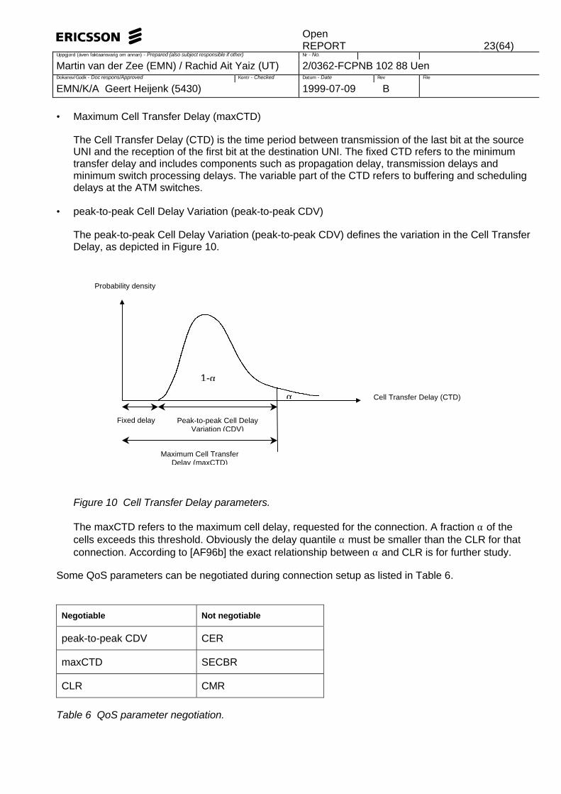
• peak-to-peak Cell Delay Variation (peak-to-peak CDV)
The peak-to-peak Cell Delay Variation (peak-to-peak CDV) defines the variation in the Cell TransferDelay, as depicted in Figure 10.
Figure 10 Cell Transfer Delay parameters.
The maxCTD refers to the maximum cell delay, requested for the connection. A fraction α of thecells exceeds this threshold. Obviously the delay quantile α must be smaller than the CLR for thatconnection. According to [AF96b] the exact relationship between α and CLR is for further study.
Some QoS parameters can be negotiated during connection setup as listed in Table 6.
Negotiable Not negotiable
peak-to-peak CDV CER
maxCTD SECBR
CLR CMR
Table 6 QoS parameter negotiation.
Cell Transfer Delay (CTD)
Probability density
Fixed delay Peak-to-peak Cell DelayVariation (CDV)
Maximum Cell TransferDelay (maxCTD)
1-α
α

OpenREPORT 24(64)
Uppgjord (även faktaansvarig om annan) - Prepared (also subject responsible if other) Nr - No.
Martin van der Zee (EMN) / Rachid Ait Yaiz (UT) 2/0362-FCPNB 102 88 UenDokansv/Godk - Doc respons/Approved Kontr - Checked Datum - Date Rev File
EMN/K/A Geert Heijenk (5430) 1999-07-09 B
QoS classes
To make things simpler, a small number of predefined QoS classes are defined, with particular valuesfor the QoS parameters (CLR, CDVT and average CTD). The five QoS classes are listed in Table 7.
QoS class QoS parameters Application
0 Unspecified Best Effort, At Risk
1 Specified Circuit emulation, Constant Bitrate
2 Specified Variable bitrate audio / video
3 Specified Connection oriented data
4 Specified Connectionless data
Table 7 ATM QoS classes.
QoS parameters that are negotiated (see Table 6), override the parameter values of the QoS class.
4.2.2.4 ATM traffic and congestion control
ATM traffic control is defined as the set of actions taken to avoid network congestion. ATM congestioncontrol is defined as the set of actions taken to minimise the intensity, spread and duration of congestion[I.371].
The ATM traffic and congestion control functions are listed in Table 8 [I.371]. Each mechanism operateson a different time scale. The functions are explained in more details, in the following text.
Time scale Traffic control Congestion control
Long Term - Virtual Path management
Connection duration - Connection Admission Control (CAC)
Round Trip Time - Fast Resource Management (FRM) - Explicit Forward Congestion Indication (EFCI)
- ABR flow control
Cell Insertion Time - Usage Parameter Control (UPC)
- Priority control / queue management
- Traffic shaping
- Selective Cell discard
- Frame discard
Table 8 Traffic control and congestion control functions.
Virtual Path management
Virtual Path (VP) management enables the segregation of different traffic types with different QoSrequirements into a single VP. Call Admission Control is simplified when Virtual Paths are used. Virtual

OpenREPORT 25(64)
Uppgjord (även faktaansvarig om annan) - Prepared (also subject responsible if other) Nr - No.
Martin van der Zee (EMN) / Rachid Ait Yaiz (UT) 2/0362-FCPNB 102 88 UenDokansv/Godk - Doc respons/Approved Kontr - Checked Datum - Date Rev File
EMN/K/A Geert Heijenk (5430) 1999-07-09 B
Paths are established on a semi-permanent basis. When a new connection is needed, a VirtualConnection within a Virtual Path is established dynamically.
Call Admission Control
To setup a Virtual Path Connection or a Virtual Channel Connection, the following information must besupplied to Call Admission Control (CAC):
• Service category (CBR, rt-VBR, nrt-VBR, ABR, UBR)
• Connection Traffic Descriptor containing Source Traffic Descriptor (PCR, SCR, MBS, MCR), CDVTand Requested conformance definition.
• Requested and acceptable QoS parameter values (peak-to-peak CDV, maxCTD, CLR)
Call Admission Control (CAC) can only accept a connection request, when the network can provide theresources to provide the QoS level requested by the new connection, while maintaining the committedQoS level of existing connections.
When a connection request is accepted by CAC, a Traffic Contract is established between the user andthe network. When the user complies to the Traffic Contract i.e. traffic compliant to the ConnectionTraffic Descriptor is injected into the network, the network will deliver the committed QoS.
Although CAC protects the network against excessive load, congestion in the network may occur (e.g.over commitment), which threatens the QoS commitments of existing connections. During periods ofcongestion cells may be dropped or in case of the ABR service feedback control may limit the trafficsource.
There are two basic strategies for CAC of Virtual Channel Connections (VCC), within a Virtual PathConnection (VPC):
• CAC based on aggregate peak demand. The sum of the Peak Cell Rate (PCR) of the VCCs issmaller than the bandwidth of the VPC.
• CAC based on statistical multiplexing. The sum of the Peak Cell Rate (PCR) of the VCCs mayexceed the bandwidth of the VPC.
Fast Resource Management
Two types of Fast Resource Management (FRM) have been proposed to enhance the ATM trafficcontrol capabilities [McDysan95]. These two proposals allow the reservation of bandwidth or bufferspace along the end-to-end path, through explicit ATM signalling. For further details see [McDysan95].
Usage Parameter Control
Once a connection is admitted by CAC, the Usage Parameter Control (UPC) starts monitoring theconnection for compliance to the Connection Traffic Descriptor, specified in the Traffic Contract. Thepurpose of UPC is to protect the network from misbehaving traffic sources that may adversely affect theQoS commitment of other connections.
The UPC can be performed on both the Virtual Path, as well as the Virtual Channel level. UPC isperformed at the VCC level at the first Virtual Channel switching point. UPC is performed on VPC level

OpenREPORT 26(64)
Uppgjord (även faktaansvarig om annan) - Prepared (also subject responsible if other) Nr - No.
Martin van der Zee (EMN) / Rachid Ait Yaiz (UT) 2/0362-FCPNB 102 88 UenDokansv/Godk - Doc respons/Approved Kontr - Checked Datum - Date Rev File
EMN/K/A Geert Heijenk (5430) 1999-07-09 B
at any Virtual Path switching point, prior to the first Virtual Channel switching point. The UPC function islocated at the UNI interface i.e. at the ATM ingress node. A similar function to UPC, but located at theNNI interface, is denoted as Network Parameter Control (NPC).
The UPC function may monitor:
• Peak Cell Rate (PCR) with the associated Cell Delay Variation Tolerance (CDVT)
• Sustainable Cell Rate (SMR) with the associated Maximum Burst Size (MBS)
The UPC function monitors the traffic by means of the Generic Cell Rate Algorithm (GCRA). The GCRAalgorithm can be specified as a virtual scheduling or a leaky bucket algorithm (with a tolerance specifiedby CDVT or MBS).
In case a single Cell Loss priority is defined, cells that do not comply are discarded. When two Cell Losspriorities are defined, cells are either tagged10 or discarded, as depicted in the Figure 11.
Figure 11 UPC control with and without cell tagging.
Priority control / queue management
The priority control and queue management schemes refer to the scheduling of cells on the output linkof the ATM switch. Different scheduling techniques, such as priority queueing and weighted round robinscheduling, have been proposed.
Traffic shaping
Traffic shaping is the modification of the traffic flow characteristics, such that the flow conforms to theTraffic Contract. In practice, this means that cells are delayed before they are transmitted. Different
10 Tagged cells are more eligible to be discarded than non-tagged cells when congestion is experienced. Thetagging information can be used in subsequent switches visited by the cell.
Conformance toCLP = 0+1 GCRACells with CLP = 0
Cells with CLP = 1
discard discard
no no
yes yes
Conformance toCLP = 0 GCRA
Cells with CLP = 0
Cells with CLP = 1
Conformance toCLP = 0+1 GCRA
discard discard
no no
yes yes
Conformance toCLP = 0 GCRA
Tag cell i.e. CLP := 1

OpenREPORT 27(64)
Uppgjord (även faktaansvarig om annan) - Prepared (also subject responsible if other) Nr - No.
Martin van der Zee (EMN) / Rachid Ait Yaiz (UT) 2/0362-FCPNB 102 88 UenDokansv/Godk - Doc respons/Approved Kontr - Checked Datum - Date Rev File
EMN/K/A Geert Heijenk (5430) 1999-07-09 B
techniques may be applied to obtain the required result, such as burst length limiting, cell spacing, etc.[I.371]. One often employed technique is the use of a token bucket to shape bursty traffic.
Explicit Forward Congestion Indication
When an ATM switch experiences congestion e.g. through buffer occupation, the switch may decide toset the Explicit Forward Congestion Indication (EFCI) in the Payload Type (PT) field of the ATM cell. Inthis way downstream nodes are informed about network congestion. The higher layers at the destinationnode may subsequently inform the source node to slow down the transmission rate. This way thefeedback control mechanism can prevent congestion collapse.
ABR flow control
The ABR service provides the ability to use resources up to the Peak Cell Rate, when there is nocongestion. The transmission rate of the source is controlled by the transmission of ResourceManagement (RM) cells, between source and destination. These RM cells convey congestioninformation and cell rate information, to control the source transmission rate. In this way the availablebandwidth is used efficiently, and the cell loss ratio is low. Through flow control, the ABR serviceprovides a better network utilisation and cell loss ratio than the UBR service. The RM cells aregenerated selectively for ABR flows, to allow fair sharing of the available resources.
Cell Loss Priority
The Cell Loss Priority (CLP) bit may be set at the source, to indicate relative priority within a VC, or at anATM switch to police traffic that is not conformant.
There are two modes of operation with relation to the Cell Loss Priority:
• CLP-transparent: The network generally ignores the CLP bit. The CLR target applies to theaggregate CLP = 0 + 1 cell flow. The tagging option does not apply to this mode.
• CLP-significant: The CLR target applies only to the CLP = 0 cell flow. Network tagging is optional (acell with CLP = 0, which is not conformant to the PCR, but conformant to the SCR will have it's CLPbit set to 1). The network makes a best-effort attempt to transmit the CLP = 1 cell flow (However,cells with CLP = 1 may be discarded in case of congestion).
The CBR service operates in CLP transparent mode only. There is one conformance definition for CLP= 0 + 1 traffic. The VBR services may operate in CLP-transparent or CLP-significant mode. For the VBRservice three different conformance definitions can be selected (dependent whether the SCR applies tothe CLP = 0 + 1 or CLP = 0 traffic, and whether tagging is applied).
When a traffic contract is established, different traffic parameters may be negotiated for all traffic (CLP =0 + 1) and high priority traffic (CLP = 0).
An ATM switch must attempt to discard cells with CLP = 1 in preference to cells with CLP = 0 duringperiods of congestion. The CLP bit indicates the eligibility of the packet to be discarded:
• Value 0 indicates a high priority and value 1 indicates that the packet is subject to discard.
• Cells generated by a source beyond the Traffic Contract have CLP 1; cells in conformance haveCLP 0.
OpenREPORT 28(64)
Uppgjord (även faktaansvarig om annan) - Prepared (also subject responsible if other) Nr - No.
Martin van der Zee (EMN) / Rachid Ait Yaiz (UT) 2/0362-FCPNB 102 88 UenDokansv/Godk - Doc respons/Approved Kontr - Checked Datum - Date Rev File
EMN/K/A Geert Heijenk (5430) 1999-07-09 B
• The network may set the CLP to 1 for those cells, which fail to conform to the Traffic Contract.
Frame discard
An AAL frame is likely to consist of more than one ATM cell. In case of congestion it is more efficient todiscard not only a single cell, but also preferably all cells of the AAL frame. This type of discardmechanism can improve the goodput and reduce network congestion. However, this mechanismrequires the detection of AAL frame boundaries at the ATM switches.
4.2.3 Mapping of Integrated Services to ATM services
In this section the mapping of Integrated Services to ATM services is evaluated. The recommendedmapping of Integrated Services to ATM services, according to RFC 2381 [RFC2381], is listed in Table 9.It should be noted that other mappings are not precluded.
Integrated Service ATM service ATM QoS class
Guaranteed Service CBR or rt-VBR 1
Controlled Load nrt-VBR or ABR11 3
Best Effort UBR or ABR 0
Table 9 Recommended mappings of Integrated Services to ATM services and QoS classes.
Before the service mappings are discussed in more detail, first some general issues are discussed.
Buffering at ATM ingress node
The traffic characteristics of an RSVP flow can be bursty. This burstiness is specified by means of atoken bucket (see Section 3.5). In general the ATM ingress node provides limited buffering at the UNIinterface. In case of variable bitrate services rt-VBR and nrt-VBR, the associated Maximum Burst Size(MBS) can be used to provide buffering inside the ATM network to support bursty traffic.
QoS parameter mapping
ATM QoS parameters for which there is no RSVP equivalent, need to be configured manually: Cell LossPriority (CLP), Cell Delay Variation (CDV), Severely Errored Cell Block Ratio (SECBR) and Cell TransferDelay (CTD).
Non conformant traffic
Traffic that is non-conformant needs to be transmitted as Best Effort traffic, according to the IntegratedServices framework, and should not adversely effect the traffic of conformant flows12. The ATM service
11 At some point in RFC 2381 the CBR is also noted as a good mapping for the Controlled Load Service (CLS).However this service is not listed as the 'recommended' mapping for CLS. The CBR service provides a higher QoSlevel than required and may provide low network utilisation (dependent on the burstiness of the source).12 In the absense of a tagging mechanism i.e. a means to identify a packet as nonconformant (and subsequentlytreat as Best Effort), the only sensible thing to do is to drop the packet as it may adversily effect conformant flowswhile travelling through the network untagged i.e. remaining to receive special treatment.
OpenREPORT 29(64)
Uppgjord (även faktaansvarig om annan) - Prepared (also subject responsible if other) Nr - No.
Martin van der Zee (EMN) / Rachid Ait Yaiz (UT) 2/0362-FCPNB 102 88 UenDokansv/Godk - Doc respons/Approved Kontr - Checked Datum - Date Rev File
EMN/K/A Geert Heijenk (5430) 1999-07-09 B
model provides the ability to tag non conformant cells with CLP = 1. The ATM service class remains thesame, however the cell is more eligible to be discarded in periods of congestion. However, the ATMstandard does not provide details how traffic with CLP = 1 should be treated. Therefore is should bechecked whether the IP BE traffic is sufficiently supported with CLP = 1 traffic. It should be noted thatATM traffic with CLP = 1 is treated differently within the ATM network, than a Best Effort VirtualConnection that has been selected to support IP BE traffic.
4.2.3.1 Guaranteed Service
The Guaranteed Service requires real-time service support and requires a delay guarantee. The CBRand rt-VBR services are the only real-time ATM services, which provide a maximum delay guarantee(i.e. maximum Cell Transfer Delay (maxCTD)).
For obvious reasons the selection of CBR in case of constant rate traffic sources and rt-VBR in case ofvariable rate traffic sources is preferable.
The Cell Loss Ration (CLR) should be selected sufficiently low to support effectively the (real-time)applications.
Parameter mapping
The following mapping is recommended for rt-VBR service [RFC2381]:
PCR = p 13
SCR = R 14
MBS = b
The following mapping is recommended for CBR service [RFC2381]:
++
=space buffer no provides node Ingress)max(
)( space buffer provides node IngressPCR
R,p
RD Cb R sumsum
The following bounds are recommended [RFC2381]:
r <= SCR <= R <= PCR <= APB
4.2.3.2 Controlled-Load Service
The UBR service does not provide QoS capabilities strict enough to support the Controlled-LoadService. The ABR service aligns the best with the Controlled-Load Service. In this case the MCR of theABR service is determined, based on the average rate r specified in the TSpec [RFC2381]. The ATM
13 In case reserved bandwidth R is greater than the peak rate p, the PCR is set to R (because a burst of size bmust be cleared from the buffer within b/R time). In case R is smaller than p, PCR may be chosen smaller than pto select a VC that is more economic (in case cost is based on PCR). In such a case the ATM ingress node mustallow sufficient buffer space (b + Csum + R Dsum) to support the peak rate p [RFC2381].14 The SCR can be assigned the average rate r without violating the Guaranteed Service (GS) delay requirementsor cell loss. However, this is against the spirit of the GS service and the additional delay inside the ATM networkmust be accounted for by the ingress node (C and D error terms).

OpenREPORT 30(64)
Uppgjord (även faktaansvarig om annan) - Prepared (also subject responsible if other) Nr - No.
Martin van der Zee (EMN) / Rachid Ait Yaiz (UT) 2/0362-FCPNB 102 88 UenDokansv/Godk - Doc respons/Approved Kontr - Checked Datum - Date Rev File
EMN/K/A Geert Heijenk (5430) 1999-07-09 B
ingress nodes should supply sufficient buffer space (at least the token bucket depth b plus additionalnetwork jitter). It should be noted that during periods of congestion the ATM network might throttle downquickly the transfer rate to the MCR rate. A source transmitting above this rate may experience highloss.
When the Controlled-Load Service is supported by the nrt-VBR service the same mapping and bufferconsiderations apply as with the Guaranteed Service to nrt-VBR service mapping in Section 4.2.3.1.
4.2.3.3 Best Effort
The UBR and ABR services are the preferred choice for support of Best Effort traffic [RFC2381]. Itshould be noted that the ABR service provides improved CLR performance and has been designedspecifically to support TCP/IP traffic. The Best Effort service does not provide traffic or resourceparameters, therefore the mapping of these parameters is not an issue.
4.2.4 VC management
Introduction
The ATM edge devices are concerned with the interworking between Integrated Services and the ATMservices, as depicted in Figure 12. This includes the translation of the RSVP reservation semantics inthe appropriate ATM VC parameters.
On the one hand ATM edge devices must support Integrated Services capabilities such as RSVPmessage handling, resource reservation, RSVP soft state maintenance, packet classification andscheduling. On the other hand ATM edge devices must support setting up, maintenance and release ofATM Virtual Connections through UNI signalling.
Figure 12 IP over ATM system elements.
The ATM ingress node triggers the establishment of a VC with appropriate QoS (when there is no oneavailable satisfying the requirements) when an RSVP Resv message is received. The informationneeded to select a proper VC is contained in the TSpec (source traffic description) and in case of theGuaranteed Service the RSpec (QoS requirements bandwidth and delay) of the Resv message. Uponreceipt of a Resv message by the ATM ingress node, the reservation request must be merged with otherrequests according to the general merging rules.
S1
S2
R1
R2
R3
ATM
IPATM
IPATM
IPATM
Virtual Connection
Path Resv
Ingress node
Egress node

OpenREPORT 31(64)
Uppgjord (även faktaansvarig om annan) - Prepared (also subject responsible if other) Nr - No.
Martin van der Zee (EMN) / Rachid Ait Yaiz (UT) 2/0362-FCPNB 102 88 UenDokansv/Godk - Doc respons/Approved Kontr - Checked Datum - Date Rev File
EMN/K/A Geert Heijenk (5430) 1999-07-09 B
RSVP requires that the Path messages and the Resv messages follow the same path. In case of IPover ATM this implies that both the Path and Resv messages must follow the same ingress and egressATM nodes. The ATM egress node is responsible for the setting of the parameters contained in theAdspec.
ATM end-points
The ATM end-point is identified by the RSVP next-hop information element contained in the Resvmessage. In case the ATM end-point is a non-RSVP capable node, the next-hop element does notidentify the proper ATM end-point. For a unicast session, the correct ATM end-point is identified by theIP next hop router. However, for a multicast session, multicast routing may not uniquely identify the IPnext hop router.
Multicast data distribution
Two types of multicast data distributions are identified:
• Multicast mesh: All data is transmitted from sender to all receivers by means of a point-to-multipointVC.
• Multicast server: All data is transmitted from sender to a multicast server through point-to-pointconnections. The server then transmits the data to all receivers over a point-to-multipoint VC.
The multicast server does not support signalling of QoS requirements. Therefore RSVP over ATM mustsupport the multicast mesh method. When the multicast server method is applied, the RSVP servicebreak bits must be set, not the global RSVP break bit. Setting the RSVP service break bit indicates thatRSVP/Integrated Services are supported, but service specific features are not supported.
ATM shortcuts
ATM provides the ability to setup a point-to-point VC i.e. shortcut directly to an ATM node outside aLogical IP Subnetwork (LIS). When shortcuts are employed, the path can be asymmetrical i.e. Path andResv message travelling a different path. RSVP does support this type of asymmetry, as only thoseRSVP messages are processed which arrive on the proper interface, denoted by the Next Hop (NHOP)information element of the Resv message
Receiver heterogeneity
Receiver heterogeneity is not supported with ATM multicasting, as all branches of the multi-cast treehave the same QoS characteristics. Receiver heterogeneity happens when receivers require differentQoS or when some receivers are satisfied with the traditional Best Effort service. RSVP heterogeneitycan be supported by ATM by proper mapping of RSVP reservation onto ATM Virtual Connection (VC).
Four different styles of mapping have been identified [RFC2382]:
Full heterogeneity
A separate multicast VC is provided for each QoS level requested.
Limited heterogeneity
OpenREPORT 32(64)
Uppgjord (även faktaansvarig om annan) - Prepared (also subject responsible if other) Nr - No.
Martin van der Zee (EMN) / Rachid Ait Yaiz (UT) 2/0362-FCPNB 102 88 UenDokansv/Godk - Doc respons/Approved Kontr - Checked Datum - Date Rev File
EMN/K/A Geert Heijenk (5430) 1999-07-09 B
Two separate multicast VCs are provided per RSVP flow: one QoS multicast VC and aBest Effort multicast VC.
Modified homogeneous
A single multicast VC is provided per RSVP flow with the maximum QoS level of the RSVPflows.
Aggregation model
Multiple RSVP flows are mapped onto a single 'large' multicast VC. This approach is similarin the way IP Integrated Services is managed over point-to-point links (e.g. T-1, DS-3). Oneproblem remains how to chose the proper QoS of the aggregate VC. Furthermore as UPCis applied to a single VC, flow segregation is compromised. The advantage of this approachis that no signalling delays are involved in setting up VCs.
A combination of receiver heterogeneity and dynamic QoS arises, when a new receiver is added with alarger QoS requirement than the existing QoS level.
Switched or Permanent VCs
Employing Integrated Services over ATM using Permanent Virtual Connection (PVC) is ratherstraightforward. In this case the Integrated Service is used similar as on any point-to-point link layertechnology. The QoS of PVCs should however be able to support the QoS of the Integrated Services.There are no delays involved in setting up VCs for the establishment of an RSVP session. However, thispermanent allocation of resource may provide low network resource utilisation. In case the networkengineering uses over-subscription to increase utilisation, the Integrated Service QoS commitment canbe compromised.
When Switched Virtual Connection (SVC) are used, flexibility is obtained through increased complexity,cost and efficiency to setup SVCs. These disadvantages could impact the integration with RSVP.Furthermore scaling issues arise when a single RSVP flow is mapped on a single SVC. RSVP mayeither send explicit messages (Pathtear and Resvtear) or a timeout occurs to indicate that thereservation is no longer needed. This triggers the release of the associated VCs. There is an inactivitytimer defined in RFC 1755 at both the ATM ingress and egress node that releases the VC, when there isinactivity for 20 minutes (default). To prevent possible interference with the RSVP release, this timershould preferably set to 'infinity'.
UNI 3.x and 4.0 do not allow the re-negotiations of the QoS parameters of a VC, i.e. once a VirtualConnection is established the QoS cannot be renegotiated15. This implies that a new VC needs to beestablished when the QoS of the existing VC is not sufficient to support the new QoS of the RSVPreservation. Some hysteresis level needs to be included to prevent too frequent setup and release ofVCs to QoS changes [RFC2382].
VCs for RSVP signaling messages
Two types of RSVP signaling messages need to be supported: Path (unicast and multicast address)and Resv (unicast address only). Therefore VCs for RSVP signaling must support both unicast andmulticast. Four different approaches are identified [RFC2382]:
15 The ITU-T has specified modification procedures to modify the Traffic Parameters of an active connection[ITU96]. However the QoS parameters may not be changed.
OpenREPORT 33(64)
Uppgjord (även faktaansvarig om annan) - Prepared (also subject responsible if other) Nr - No.
Martin van der Zee (EMN) / Rachid Ait Yaiz (UT) 2/0362-FCPNB 102 88 UenDokansv/Godk - Doc respons/Approved Kontr - Checked Datum - Date Rev File
EMN/K/A Geert Heijenk (5430) 1999-07-09 B
Use the same VC for RSVP signaling and data
The advantage is that no additional VCs are needed, and setup delays are avoided.However, the RSVP signaling may suffer from nonconforming data traffic.
Single VC per RSVP session
The advantage is that a separate VC protects the RSVP signaling from excessive loss as aseparate traffic contract is established for RSVP signaling. However, this requires twice asmuch VCs.
Single point-to-multipoint VC multiplexed among sessions
Several RSVP sessions may share the same point-to-multipoint VC to transmit signalingmessages. This requires that the ATM ingress and ATM egress node(s) are the same.Some multiplexing gain is obtained at the expensive of complexity of handling changingegress nodes.
Multiple point-to-point VCs multiplexed among sessions
In this scheme several point-to-point VCs are needed to support a point-to-multipoint RSVPsignaling. A single point-to-point VC however can provide high multiplexing gain. VC setupsignaling cost is reduced as with point-to-point VCs a reverse connection can beestablished as the same time the forward connection is established. The QoS levelrequired for the VC depends on the multiplexing gain that is expected.
4.2.5 Conclusions
ATM provides a rich QoS architecture, which makes it suitable to support different types of services withvarying QoS requirements. However, the connection-oriented nature of ATM makes it less suitable tosupport connectionless IP efficiently. In Section 5.2 a new architecture called Multi-Protocol LabelSwitching (MPLS) is discussed. This architecture tries to use the best of both worlds by integrating ATMand IP.
4.3 IEEE 802 LAN Technologies16
4.3.1 Introduction
The IEEE has defined standards for different Local Area Networks (LAN) technologies. This is donewithin the 802 project. The defined standards offer the same MAC layer datagram service to higher layerprotocols such as IP.
Although the defined standards offer the same MAC layer datagram service, they provide differentdynamic behaviour characteristics. These dynamic behaviour characteristics are important whenconsidering the ability of the defined standards to support real-time services.
In this section we will focus on the capabilities of different IEEE 802 LAN Technologies in relation tosupporting Integrated Services. An example network containing an IEEE 802 segment17 is given by
16 The content of this section is mainly extracted from [IDISSL98]17 A segment is a physical Layer 2 segment that is shared by one or more senders [IDISSL98].

OpenREPORT 34(64)
Uppgjord (även faktaansvarig om annan) - Prepared (also subject responsible if other) Nr - No.
Martin van der Zee (EMN) / Rachid Ait Yaiz (UT) 2/0362-FCPNB 102 88 UenDokansv/Godk - Doc respons/Approved Kontr - Checked Datum - Date Rev File
EMN/K/A Geert Heijenk (5430) 1999-07-09 B
Figure 13.
PHY
Ethernet (IEEE 802.3)
IP (RSVP)
APP
PHY PHY
Ethernet (IEEE 802.3) PPP
IP Router (RSVP)
PHY
PPP
PHY
IEEE 802.5
IP Router (RSVP)
PHY
IEEE 802.5
PHY
Ethernet (IEEE 802.3)
PHY
Ethernet (IEEE 802.3)
IP (RSVP)
APP
IP router Host IP router IEEE 802.1 Bridge Host
Figure 13 Network containing IEEE 802 segments
4.3.2 Frame Forwarding in IEEE 802 Networks
Although we use the term IEEE 802 style networks, different types of IEEE 802 networks differ in theway they support Integrated Services. Some IEEE 802 networks use a priority mechanism for queueingand medium access while others do not. In case an IEEE 802 network uses a priority mechanism, theuser_priority is carried explicitly in the MAC frame. This user_priority serves as a label, making itpossible for the downstream nodes to discriminate frames within a data stream in different classeswithout parsing the frames in more detail.
4.3.2.1 Ethernet/IEEE 802.3
Figure 14 shows the MAC frame format used by IEEE 802.3 networks.
PreambleDestination
addressSourceaddress
Pad
Start of frame delimiter Length/Type Checksum
Data
2 or 617 2 or 6 2 0 - 1500 0 - 46 4Bytes
Figure 14 MAC frame format of IEEE 802.3
As can be seen in Figure 14, there is no explicit traffic class or user_priority carried in the IEEE 802.3MAC frame. As a result, frames belonging to different flows can only be distinguished by parsing furtherinto higher layer protocol fields in the frame. Another possible way of distinguishing frames belonging todifferent flows, is to make use of the Length/Type field. In order to be able of performing such adistinction, new Ethertypes (values of Length/Type field) must be defined and standardised.Note that an IEEE 802.1Q encapsulation [IEEE8021Q] may also be used, providing an explicituser_priority field on top of the basic MAC frame format.As Ethernet is a shared medium with no access priorities, all users attached to an Ethernet can getaccess to the medium with equal probability. For this reason, there is no upper bound for the maximum

OpenREPORT 35(64)
Uppgjord (även faktaansvarig om annan) - Prepared (also subject responsible if other) Nr - No.
Martin van der Zee (EMN) / Rachid Ait Yaiz (UT) 2/0362-FCPNB 102 88 UenDokansv/Godk - Doc respons/Approved Kontr - Checked Datum - Date Rev File
EMN/K/A Geert Heijenk (5430) 1999-07-09 B
access latency, which means that Ethernet cannot provide a delay bound and, as a result, does notprovide explicit real-time service support.
4.3.2.2 Token Ring/IEEE 802.5
Figure 15 shows the MAC frame format used by IEEE 802.5 networks.
SDDestination
addressSourceaddress
Checksum EDData
2 or 61 2 or 6Limited by
Token Hold Timer 4 1Bytes
AC FC FS
Frame Control
Access control
Starting delimiter
Ending delimitrer
Frame status
1 1 1
Figure 15 MAC frame format of IEEE 802.5
The IEEE 802.5 standard has defined a priority mechanism that can be used to control the queueing offrames and the access of frames to the shared media. For this purpose, IEEE 802.5 networks use theAccess Control (AC) and the Frame Control (FC) fields of a Logical Link Control (LLC) frame. The firstand the last three bits of the AC field, the Token Priority bits and the Reservation bits respectively,regulate access to the ring. The last three bits of the FC field, the User Priority bits, are obtained fromthe next higher layer in the user_priority parameter when transmission of a frame is requested. Theuser_priority is also used to establish the Access Priority used by the MAC.
IEEE 802.5 uses a concept of Reserved Priority (see also [OEC8025]). A station can reserve themedium by setting the Reservation bits. When a free token is circulating, only a station having anAccess Priority greater than or equal to the Reserved Priority in the token can make use of the token.We expect that this reservation mechanism can gratefully be used as part of a resource reservationmechanism. Because the transmission time of stations in a IEEE 802.5 network is not allowed to belonger than the Token Hold Time (i.e. transmission time is bound), and because the number of stationson a IEEE 802.5 network is bound, the access delay is also bound. However, Token Ring does notexplicitly support real-time service.
4.3.2.3 Fiber Distributed Data Interface (FDDI)
Like Token Ring, FDDI provides a priority mechanism than can be used to control the queueing offrames for transmission and the access of frames to the shared media. However, FDDI provides besidesthe asynchronous service also a synchronous service, which provides a delay bound. In other words,FDDI explicitly supports real-time services.
4.3.2.4 Demand Priority/IEEE 802.12
IEEE 802.12 is a standard for a shared 100 Mbps LAN. The MAC protocol for this standard is calledDemand Priority. Data packets from al network nodes are served using a Round Robin mechanism. Forthe transmission of frames, either the IEEE 802.3 or IEEE 802.5 frame format is used.
The main characteristics of the IEEE 802.12 standard with respect to QoS are the supports of twoservice priority levels, normal priority and high priority, and the order of service for each of these. If theIEEE 802.5 frame format is used for data transmission, then the user_priority is encoded in the FC field(see Figure 15) in the IEEE 802.5 frame header. When the IEEE 802.3 frame format is used for data

OpenREPORT 36(64)
Uppgjord (även faktaansvarig om annan) - Prepared (also subject responsible if other) Nr - No.
Martin van der Zee (EMN) / Rachid Ait Yaiz (UT) 2/0362-FCPNB 102 88 UenDokansv/Godk - Doc respons/Approved Kontr - Checked Datum - Date Rev File
EMN/K/A Geert Heijenk (5430) 1999-07-09 B
transmission, the user_priority is encoded in the starting delimiter of the IEEE 802.12 frame header.Besides these two frame formats that can be used for the transmission of data frames, the IEEE 802.1Qencapsulation [IEEE8021Q] with its own user_priority field may be applied.
Note that the IEEE 802.12 standard does not define an explicit real-time service support.
4.3.2.5 Characteristics of different IEEE 802 networks
Some of the characteristics of different IEEE 802 networks are listed in Table 10. Other networks thathave not been considered are IEEE 802.11 Wireless LANs and Bluetooth networks.
Network type Priority mechanism forqueueing and medium access
Explicit real-timeservice support
802.3 Ethernet (10 Mbps / 100 Mbps) No No
802.5 Token ring (4 - 16 Mpbs) Yes (eight levels)18 No
FDDI (100 Mpbs) Yes (eight levels)19 Yes20
802.12 Demand Priority (100 Mbps) Yes (high and low) No
Table 10 QoS support IEEE 802-style networks [IDISSL98].
Note that none of the listed 802 networks (in Table 10) provide explicit support for QoS.
4.3.3 The Bandwidth Manager
According to [IDISSL98], there are requirements that should drive the design of an architecture forsupporting Integrated Services in IEEE 802 style networks. These requirements concern the functions ofResource reservation, Admission Control, Flow separation and scheduling, Policing and shaping etc.
[IDISSL98] introduces an entity that performs these functional requirements. This entity is referred to asBandwidth Manager (BM). The Bandwidth Manager is responsible for making it possible for anapplication or higher layer protocol to request QoS from the datalink layer of a segment and consists of:
• Requester Module
• Bandwidth Allocator
• Communication Protocols
These components will be clarified in the following subsections.
18 The token contains both a priority field and reservation field. The priority field indicates the current priority levelrequired to seizing the token. The reservation field can be used to signal higher priority traffic presence. By propersetting of the token's priority and reservation fields a distributed priority queuing system is implemented [STAL97].19 The priority level refers to the 'asynchronous' service only.20 Bandwidth can be assigned to 'synchronous' services by way of a management protocol. Unused bandwidth by'synchronous' service may be used by the 'asynchronous' service [STAL97].

OpenREPORT 37(64)
Uppgjord (även faktaansvarig om annan) - Prepared (also subject responsible if other) Nr - No.
Martin van der Zee (EMN) / Rachid Ait Yaiz (UT) 2/0362-FCPNB 102 88 UenDokansv/Godk - Doc respons/Approved Kontr - Checked Datum - Date Rev File
EMN/K/A Geert Heijenk (5430) 1999-07-09 B
4.3.3.1 Requester Module
This component resides in every end station21 in the subnet22 and provides an interface between higherlayer protocols (RSVP, ST2, SNMP etc.) and the Bandwidth Manager.
To initiate a reservation in the link layer domain, the following parameters must be passed to theRequester Module:
• The service desired (Guaranteed Service or Controlled Load)
• The traffic descriptors contained in TSpec
• The RSpec specifying the amount of resources to be reserved
These parameters can be extracted from the RSVP PATH and RSVP RESV messages. Furthermore,the Requester Module must convert the network layer addresses of the endpoints to link layeraddresses. A link layer address is needed to route a packet trough the IEEE 802 subnet to thedestination at the other end of IEEE 802 subnet. Furthermore the Requester Module must convert therequest into an appropriate format which is understood by other components of the Bandwidth Manager.Finally the Requester Module must return the status of requests processed by the Bandwidth Managerto the invoking application or higher layer protocol.
4.3.3.2 Bandwidth Allocator
The Bandwidth Allocator is responsible for performing admission control and maintaining state about theallocation of resources in the subnet. It processes the requests of various services, made by the endstations.
Communication between the Bandwidth Allocator and the end stations take place through theRequester Module. The Bandwidth Allocator is also responsible for deciding how to label flows. Forinstance, the Bandwidth Allocator may, based on the admission control decision, indicate to theRequester Module which priority level a particular flow must be tagged with.
4.3.3.3 Communication Protocols
Communication takes place at different levels. First of all, communication takes place between thehigher layer protocols and the Requester Module. For this sake, the Bandwidth Manager must defineprimitives for the application to initiate reservations, query the Bandwidth Allocator about availableresources, change and delete reservation etc.
Communication also takes place between the Requester Module and the Bandwidth Allocator. Thisprotocol will specify the messages that must be exchanged between the Requester Module and theBandwidth Allocator in order to service various requests by the higher layer entity.
Finally communication takes place between peer Bandwidth Allocators when there is more than oneBandwidth Allocator in the subnet. There should be an election procedure that decides which BandwidthAllocator is responsible for which segment in case there are segments containing multiple BandwidthAllocators. The Bandwidth Allocators must be able to correctly handle the scenario in which a requestfor resources is made along a domain of multiple Bandwidth Allocators (subsequent segments).
21 An end station is a station, with Layer 3 capabilities, at the border of the Layer 2 segment.22 A subnet can contain multiple segments

OpenREPORT 38(64)
Uppgjord (även faktaansvarig om annan) - Prepared (also subject responsible if other) Nr - No.
Martin van der Zee (EMN) / Rachid Ait Yaiz (UT) 2/0362-FCPNB 102 88 UenDokansv/Godk - Doc respons/Approved Kontr - Checked Datum - Date Rev File
EMN/K/A Geert Heijenk (5430) 1999-07-09 B
Bandwidth Allocators must also be able to use their communication with each other to backup andrecover in the event of failure.
4.3.4 Centralised versus distributed implementations of the Bandwidth Manager
The Bandwidth Manager can be either centralised or distributed. Centralised or distributed refers to theimplementation of the Bandwidth Allocators, the components responsible for resource reservation andadmission control. In both the centralised and distributed implementation, the Requester Module mustbe present in all end stations that desire to make reservation.
4.3.4.1 Centralised Bandwidth Allocator
A Bandwidth Manager with a centralised Bandwidth Allocator implementation is shown in Figure 16.
Layer 2
RM
App
Layer 2 Layer 2 Layer 2
RM
App
Layer 2
BA
RM Requester Module BA Bandwidth Allocator App Application or higher layer protocol (e.g. RSVP)
RSVP Host/Router
Intermediate Bridge/Switch
RSVP Host/Router
Intermediate Bridge/Switch
Figure 16 Bandwidth Manager with a Centralised Bandwidth Allocator [IDISSL98]
When a centralised Bandwidth Allocator is used, the Bandwidth Allocator will be responsible foradmission control decisions for the entire subnet.
As can be seen from Figure 16, every end station (host/router) contains a Requester Module, whileintermediate bridges and switches do not need to have any functions of the Bandwidth Manager sincethey will not participate actively in admission control.
When a Requester Module requests a reservation it initiates communication with its (centralised)Bandwidth Allocator. For larger subnets, a single Bandwidth Allocator may not be able to handlereservations for the entire subnet. In such case, it is necessary to deploy multiple Bandwidth Allocators,each managing the resources of a non-overlapping subset of segments.
In order to be able to reserve resources on appropriate segments, the Bandwidth Allocator must havesome model of the Layer 2 topology of the subnet.

OpenREPORT 39(64)
Uppgjord (även faktaansvarig om annan) - Prepared (also subject responsible if other) Nr - No.
Martin van der Zee (EMN) / Rachid Ait Yaiz (UT) 2/0362-FCPNB 102 88 UenDokansv/Godk - Doc respons/Approved Kontr - Checked Datum - Date Rev File
EMN/K/A Geert Heijenk (5430) 1999-07-09 B
4.3.4.2 Distributed Bandwidth Allocator
A Bandwidth Manager with a distributed Bandwidth Allocator implementation is shown in Figure 17.
Layer 2
RM/BA
App
Layer 2 Layer 2 Layer 2
RM/BA
App
BA
RM Requester Module BA Bandwidth Allocator App Application or higher layer protocol (e.g. RSVP)
RSVP Host/Router
Intermediate Bridge/Switch
RSVP Host/Router
Intermediate Bridge/Switch
BA
Figure 17 Bandwidth Manager with a Distributed Bandwidth Allocator [IDISSL98]
When a Bandwidth Manager with a distributed Bandwidth Allocator is used, all devices in the subnethave Bandwidth Manager functionality. Besides this fact, all end hosts are still required to have aRequester Module.
Unlike the centralised Bandwidth Allocator implementation of Section 4.3.4.1, all stations participateactively in admission control and each Bandwidth Allocator needs only local topology information since itis only responsible for the resources on the segment that is directly connected to it.
4.3.5 Model of the Bandwidth Manager in a Network
We now describe how the model of the Bandwidth Manager fits within the existing IETF IntegratedService model of IP hosts and routers. We first describe how the model is implemented in end stations(hosts / routers). Subsequently we describe the implementation in Layer 2 switches.
4.3.5.1 End Station Model
An end station can be either a router or a host. In an end station there is a client handling QoS. Forinstance, the client runs an RSVP process which:
• Presents a session establishment to applications
• Signals over the network
• Programs a scheduler and classifier in the driver
• Interfaces to a policy control module
Figure 18 shows RSVP in a sending end station

OpenREPORT 40(64)
Uppgjord (även faktaansvarig om annan) - Prepared (also subject responsible if other) Nr - No.
Martin van der Zee (EMN) / Rachid Ait Yaiz (UT) 2/0362-FCPNB 102 88 UenDokansv/Godk - Doc respons/Approved Kontr - Checked Datum - Date Rev File
EMN/K/A Geert Heijenk (5430) 1999-07-09 B
ApplicationRSVP
Process
PolicyControl
Classifier PacketScheduler
AdmissionControl
RSVP
data
Figure 18 RSVP in a sending End Station [IDISSL98]
Because switches and bridges don’t have Layer 3 functionality, the RSVP process must be translated toanother process taking place at Layer 2. For this purpose ISSLL functionality is added to the sender andreceiver end station. We explain this in the following subsections.
4.3.5.1.1 Request to Layer 2 ISSLL
The local admission control entity (see Figure 18) within a host or router is responsible for mappingLayer 3 session establishment requests into Layer 2 language. The upper layer entity makes requests inthe form:
[“May I reserve for traffic with <traffic characteristic> with <performance requirement> from <here> to<there> and how should I label it?”]([IDISSL98])
4.3.5.1.2 ISSLL at sending End Station
The ISSLL functionality in the sender (with relation to data flow) is depicted in Figure 19. The functionsof the Requester Module may be summarised as follows:
• Maps the endpoints of the conversation to Layer 2 addresses in the LAN (may use ARP).
• Communicates with any Local Bandwidth Allocator module for local admission control decisions.
• Formats an SBM (Subnet Bandwidth Manager) request to the subnetwork with the mapped addressand flow/filter specs.
• Receives a response from the subnetwork and reports the admission control decision to the higherlayer entity along with any negotiated modifications to the session parameters.
• Saves any returned user_priority to be associated with this session in a “802 Header” table. This willbe used when constructing the Layer 2 headers for future data packets belonging to this session.
The Bandwidth Allocator is only present when a distributed Bandwidth Allocator model is implemented.

OpenREPORT 41(64)
Uppgjord (även faktaansvarig om annan) - Prepared (also subject responsible if other) Nr - No.
Martin van der Zee (EMN) / Rachid Ait Yaiz (UT) 2/0362-FCPNB 102 88 UenDokansv/Godk - Doc respons/Approved Kontr - Checked Datum - Date Rev File
EMN/K/A Geert Heijenk (5430) 1999-07-09 B
Its function is basically to apply local admission control for the outgoing link bandwidth and driver’squeueing resources.
Addressmapping
RequesterModule
BandwidthAllocator
ClassifierPacket
Scheduler
SBMsignalling
data
802Header
to/fromRSVP
fromIP
mandatory function
optional function
Figure 19 ISSLL in a Sending End Station [IDISSL98]
4.3.5.1.3 ISSLL at receiver End Station
The ISSLL functionality in the receiving end station is shown by Figure 20.
The functions of the Requester Module may be summarised as follows:
• Handles any received SBM protocol indication.
• Communicates with any local Bandwidth Allocator for local admission control decisions.
• Passes indications up to RSVP if OK
• Accepts confirmations from RSVP (RESV messages) and relays them back via SBM signallingtowards the requester
• May program a receive classifier and scheduler, if used, to identify traffic classes of receivedpackets and accord them appropriate treatment (e.g. reservation of buffers for particular trafficclasses).
• Programs the receiver to strip away link layer header information from received packets.

OpenREPORT 42(64)
Uppgjord (även faktaansvarig om annan) - Prepared (also subject responsible if other) Nr - No.
Martin van der Zee (EMN) / Rachid Ait Yaiz (UT) 2/0362-FCPNB 102 88 UenDokansv/Godk - Doc respons/Approved Kontr - Checked Datum - Date Rev File
EMN/K/A Geert Heijenk (5430) 1999-07-09 B
The Bandwidth Allocator, present only in a distributed implementation, applies local admission control tosee if a request can be supported with appropriate local receive resources.
RequesterModule
ClassifierPacket
Scheduler
Strip 802Header
to IPto
RSVP
mandatory function
optional function
BandwidthAllocator
SBMsignalling
data
Figure 20 ISSLL in a Receiving End Station [IDISSL98]
4.3.5.2 Switch23 Model
When the Centralised Bandwidth Allocator Model is implemented, switches do not take part in theadmission control process. A centralised Bandwidth Allocator (e.g. Subnet Bandwidth Manager)implements admission control.
This centralised Bandwidth Allocator may be co-located with a switch but its functions would notnecessary then be closely tied with the switch’s forwarding functions as is the case with a distributedBandwidth Allocator where access to the switch’s forwarding table is required (see SBM propagationmodule in this Section).
The ISSLL functions of a switch, in the case a distributed Bandwidth Allocator is used, are shown byFigure 21.
23 A switch is Layer 2 forwarding device as defined by IEEE 802.1D [IDISSL98]

OpenREPORT 43(64)
Uppgjord (även faktaansvarig om annan) - Prepared (also subject responsible if other) Nr - No.
Martin van der Zee (EMN) / Rachid Ait Yaiz (UT) 2/0362-FCPNB 102 88 UenDokansv/Godk - Doc respons/Approved Kontr - Checked Datum - Date Rev File
EMN/K/A Geert Heijenk (5430) 1999-07-09 B
INSBM
SBMprop.
OUTSBM
LocalAdmission
Control
LocalAdmission
Control
trafficclass map& police
FilterDatabase(classifier)
Queue &Packet
Schedule
egresstraffic
class map
data in data out
SBM signalling SBM signalling
mandatory function
optional function
Figure 21 ISSLL in a Switch
The following entities can be defined within a switch:
• Local Admission Control Module:Accounts for the available bandwidth on the link attached to that port.
• Input SBM Module (IN SBM):One Instance on each port performs the “network” side of the signalling protocol for peering withclients or other switches.Holds knowledge about mapping of IntServ classes to user_priority.
• SBM Propagation Module (SBM prop.):Relays requests that have passed admission control at the input port to the relevant output ports’SBM modules. This requires access to switch’s forwarding table (Layer 2 “routing table” cf. RSVPModel) and port spanning tree state.
• Output SBM Module (OUT SBM):Forwards requests to the next Layer 2 or Layer 3 hop.
• Classifier, Queue an Scheduler Module:The Classifier Module identifies the relevant QoS information from incoming packets and uses this,together with the normal bridge forwarding database, to decide at which output port and traffic classto queue the packet.The Queue and Scheduler hold the output queues for ports and provide the algorithm for serving thequeues for transmission onto the output link in order to provide the promised IntServ service.
• Ingress Traffic Class Mapping and Policing (optional):

OpenREPORT 44(64)
Uppgjord (även faktaansvarig om annan) - Prepared (also subject responsible if other) Nr - No.
Martin van der Zee (EMN) / Rachid Ait Yaiz (UT) 2/0362-FCPNB 102 88 UenDokansv/Godk - Doc respons/Approved Kontr - Checked Datum - Date Rev File
EMN/K/A Geert Heijenk (5430) 1999-07-09 B
Default behaviour is to pass packets through unchanged.May police the data within traffic classes for conformance to the negotiated parameters.May discard packets or re-map the user_priority.
• Egress Traffic Class Mapping Module (optional):Default behaviour is to pass packets through unchanged.May perform re-mapping of traffic classes on a per output basis.
On receipt of an admission control request, a switch performs the following actions, using SBM as anexample:
• If the ingress SBM is the “designated24 SBM” (DSBM) for this link, it matches the requested servicewith the available traffic classes and chooses the “best” one. It ensures that, if this reservation issuccessful, the value of user_priority corresponding to that traffic class is passed back to the client.The ingress DSBM observes the current state of allocation of resources on the input port/link andthen determines whether the new resource allocation from the mapped traffic class can beaccommodated. If accepted, the request is passed to the SBM propagation module.
• If the SBM is not the “Designated SBM” for this link, then it directly passes the request on to thereservation propagator.
• The SBM propagation module relays the request to the bandwidth accountants on each of theswitch’s outbound links to which this reservation would apply. This implies an interface torouting/forwarding database.
• The egress local admission control module observes the current state of allocation of queueingresources on its outbound port and bandwidth on the link itself and determines whether the newallocation can be accommodated. This is a local decision which still can be refused by further Layer2 hops through the network
• If the request is accepted by this switch, it is propagated on each output link selected. Anyuser_priority described in the forwarded request must be translated according to any egressmapping table. Furthermore, the switch must notify the client of the user_priority to be used forpackets belonging to that flow. (Here, it is assumed that admission control succeeds; However,downstream switches may refuse the request)
• If this switch wishes to reject the request, it can do so by notifying the original client using its Layer 2address.
4.3.6 Int-serv Mappings on IEEE 80225
We now describe the mapping of IP-level flows into appropriate IEEE user_priority classes. In order toperform this mapping, a multidimensional vector of parameters (e.g. bandwidth, delay, jitter and serviceclass) must be mapped onto a set of user_priority traffic classes whose default behaviour in Layer 2switches is unidimensional. 24 In some cases, multiple SBMs will exist on a single Layer 2 segment. In such cases, one of those SBMs will be
elected to become a designated SBM (DSBM). The DSBM is the active SBM on a segment. The other SBMswill serve as backup SBMs.
25 The content of this section is mainly extracted from [IDISSMP99].

OpenREPORT 45(64)
Uppgjord (även faktaansvarig om annan) - Prepared (also subject responsible if other) Nr - No.
Martin van der Zee (EMN) / Rachid Ait Yaiz (UT) 2/0362-FCPNB 102 88 UenDokansv/Godk - Doc respons/Approved Kontr - Checked Datum - Date Rev File
EMN/K/A Geert Heijenk (5430) 1999-07-09 B
Table 11 presents the default mapping from delay targets to IEEE 802.1 user_priority classes.
user_priority Service
0 Default, assumed to be Best Effort
1 Reserved, less than Best Effort
2 Reserved
3 Reserved
4 Delay Sensitive, no bound
5 Delay Sensitive, 100ms bound
6 Delay Sensitive, 10ms bound
7 Network Control
Table 11 Example user_priority to service mappings
Note that the mapping of Table 11 does not define what mechanisms or algorithms a network elementmust perform to implement these mappings.
4.4 Low-bitrate links
According to [IDISLBL99], up to now, newly developed services (e.g. Integrated Services) could not beused over forwarding paths that include low-bitrate links. The encapsulation formats used on these linksare not appropriate for the simultaneous transport of arbitrary data and real-time information, which hasto meet stringent delay requirements. Another problem concerning the in-time delivery of real-timepackets arises if large packets cannot be pre-empted in order to allow the real-time packets to be sent.In addition, the header overhead associated with the protocol stacks used is prohibitive on low-bitratelinks, where compression down to a few dozen bytes per real-time information packet is often desirable.
[IDISLBL99] describes an approach for addressing these problems. The main components of thearchitecture are:
• A real-time encapsulation format for asynchronous and synchronous low-bitrate links
• A header compression architecture optimised for real-time flows
• Elements of negotiation protocols used between routers (or between hosts and routers)
• Announcement protocols used by applications to allow this negotiation to take place.
[IDISLSN99] defines the mapping of Integrated Services “Controlled Load” and “Guaranteed Service”onto low-bandwidth links.

OpenREPORT 46(64)
Uppgjord (även faktaansvarig om annan) - Prepared (also subject responsible if other) Nr - No.
Martin van der Zee (EMN) / Rachid Ait Yaiz (UT) 2/0362-FCPNB 102 88 UenDokansv/Godk - Doc respons/Approved Kontr - Checked Datum - Date Rev File
EMN/K/A Geert Heijenk (5430) 1999-07-09 B
5 Wireless access technology requirements
5.1 Introduction
During the last decade, the number of wireless and mobile communication users has increased very fastas well as the number of Internet users.
Besides this increasing number of users, a convergence between mobile and wireless communicationon one hand and the Internet on the other hand is perceptible. This convergence puts constraints on thewireless and mobile technologies used for accessing the Internet, especially when QoS is also to beprovided to mobile and wireless users.
In this chapter the requirements that are posed on the underlying wireless link layer to provide a betterservice than that provided by Best-Effort service are identified. The requirements are not only identifiedfrom an Integrated Service point of view, but also from the Multi-Protocol Label Switching andDifferentiated Services point of view. Each requirement is denoted by Rx.
First the requirements originating from the Multi-Protocol Label Switching (MPLS) architecture arediscussed in Section 5.2. Next the requirements originating from the Differentiated Services architectureare presented in Section 5.3. Finally the requirements to support Integrated Services over wireless linksare discussed in Section 5.4.
5.2 Multi-Protocol Label Switching
The Multi-Protocol Label Switching (MPLS) architecture integrates IP network layer routing with datalinklayer label swapping [IDMPLS97], [IDMPLS99]. MPLS uses the best of both worlds to provide highspeed IP networking. In the following it is assumed that the reader is familiar with the basic MPLSterminology. For an introduction to MPLS see [VISWA98], [ZEE99].
To identify the requirements MPLS puts on the underlying layer 2, the reader is reminded that MPLSintegrates layer 3 and 2 functionality. Therefore it is difficult to separate layer 2 and 3 functionality. In thefollowing, the requirements to support MPLS are identified, without discussing whether this is layer 2 or3 functionality.
The basic requirements for a wireless access technology to support MPLS are:
R1 Mapping of incoming IP packets, into the MPLS domain, at the Label Edge Router (LER) to aForward Equivalence Class (FEC), and removal of labels for outgoing IP packets.
R2 Establishment of Label Switched Paths (LSP) through network routing protocols. LSPs may beestablished through explicit routing or hop-by-hop routing. Sufficient facilities should be provided todetect or prevent loops in the LSP. Dependent on the routing capabilities, point-to-point, multipoint-to-point, point-to-multipoint and multipoint-to-multipoint LSPs may be established.
R3 The Label Switched Router (LSR) needs to support label swapping for forwarding incomingpackets. When hierarchical routing is supported, the LSR needs to support label stacking. Tosupport multipoint-to-point LSPs, the LSR need to support label merging.
R4 The LSR needs to execute the procedures listed in the Next Hop Label Forwarding Entry (NHLFE)e.g. next hop determination, decrementing TTL, etc.

OpenREPORT 47(64)
Uppgjord (även faktaansvarig om annan) - Prepared (also subject responsible if other) Nr - No.
Martin van der Zee (EMN) / Rachid Ait Yaiz (UT) 2/0362-FCPNB 102 88 UenDokansv/Godk - Doc respons/Approved Kontr - Checked Datum - Date Rev File
EMN/K/A Geert Heijenk (5430) 1999-07-09 B
R5 The LSR needs to support label distribution, through the use of a Label Distribution Protocol (LDP).The label mapping information is stored in the Label Information Base (LIB).
5.3 Differentiated Services
The Differentiated Services (DS) architecture [RFC2475] is proposed as a response to the scalabilitylimitations of the Integrated Services (IS) concept [RFC1633]. The DS architecture reduces the stateinformation stored in the network, compared to IS, by providing QoS services for a limited number ofclasses. The QoS class is indicated by the Differentiated Service byte (DS-byte) contained in the headerof each IP packet. In the following it is assumed that the reader is familiar with the basic DS terminology.
Requirements Differentiated Services put on the wireless access network:
R1 Service Level Agreements (SLA) need to be established between wireless access network andinterconnection network. An SLA may be either static or dynamic.
R2 Marking of IP packets, i.e. setting the DS-byte. Possibly the source marks the packets but at leastthe ingress node needs to (re)mark the packets.
R3 Classification, policing and (re)shaping incoming traffic, into the DS domain, at the ingress nodebased on the SLA.
R4 An admission control function for resource requests, in case of dynamic SLAs and BandwidthBrokers (BB).
R5 Implementation of the Per-Hop-Behavior (PHB), as defined by the DS architecture. The PHBs areexplained in more detail below.
The basic building block of the Differentiated Services (DS) concept, which provides servicedifferentiation, is the packet forwarding treatment. This packet forwarding treatment is defined by thePer-Hop-Behavior (PHB) of the DS service. The PHB defines the externally observable forwardingbehavior packets with the same DS-byte exhibit when forwarded by a DS node. Two PHB proposalshave reached the status of standards track RFCs: Expedited Forwarding (EF) [RFC2598], formerlyreferred to as Premium service [IDDIFF97], and Assured Forwarding (AF) [RFC2597]. Any wirelessaccess network, part of a Differentiated Services domain, should support at least one of these PHBs.
Expedited Forwarding
The Expedited Forwarding (EF) PHB is suitable for applications requiring low delay and low jitterservices. Examples of these applications are Internet Telephony, videoconferencing, or Virtual PrivateNetworks (VPN)). The EF PHB does not provide quantified guarantees on jitter or delay, but theseparameters are assumed to be sufficiently low, to support these applications.
The EF service is based on two assumptions: the traffic entering the DS domain is conditioned (i.e.policing and shaping is applied at the ingress node) and there is a minimum departure rate of the EFtraffic at each intermediate DS compliant node. These two assumptions are the basis to provide lowdelay and low jitter service. EF traffic, upon arrival at an intermediate node, should always see an(almost) empty queue. As a result, the average queue length on the end-to-end path is kept small.
Possibly the percentage of EF traffic in the network is kept low, through proper use of Service LevelAgreements and traffic policing, to provide low delay, low jitter and assured bandwidth. However,unevenly distributed traffic may cause bottlenecks in some parts of the network, which may be removed
OpenREPORT 48(64)
Uppgjord (även faktaansvarig om annan) - Prepared (also subject responsible if other) Nr - No.
Martin van der Zee (EMN) / Rachid Ait Yaiz (UT) 2/0362-FCPNB 102 88 UenDokansv/Godk - Doc respons/Approved Kontr - Checked Datum - Date Rev File
EMN/K/A Geert Heijenk (5430) 1999-07-09 B
by traffic engineering or constraint-based routing [ZEE99].
Assured Forwarding
The Assured Forwarding (AF) PHB is suitable for applications requiring better than best-effort service.Assured service is suitable for adaptive applications, which can tolerate some loss, and applicationsrequiring assured level of transmission over a long period of time. The AF PHB group provides deliveryof IP packets in four independent forwarded AF classes (class 1 until 4) [RFC2597]. Node resources,such as buffer space and bandwidth, are reserved for a single class. Packet ordering is preserved withina single class. Within a single class, three drop precedence values can be assigned.
The AF service aims to provide service characteristics, as experienced in a lightly loaded network. Moreprecisely: an AS profile is characterised by an (average) bitrate and a token bucket burst filter. Trafficthat conforms to the AS profile is denoted as in-profile traffic, otherwise it is denoted as out-of-profile.The AF PHB assures that in-profile traffic will experience service similar to a lightly loaded network. Out-of-profile traffic is (re)marked at ingress node to a PHB which is more eligible to packet drop, comparedto in-profile traffic.
5.4 Integrated Services
5.4.1 General requirements
The general requirements, Integrated Services pose on the underlying link technology, are perfectlyexpressed by the ISSLL working group. The ISSLL working group has identified four points that mustaddressed for each candidate technology:
[...
• Service mappings. Service mappings define the way that the link layer technology is used toprovide a particular IntServ traffic management service, such as controlled-load or guaranteed-delay.
• Setup protocol mappings. Setup protocol mappings define how an internet- level setup protocolsuch as RSVP is implemented or mapped onto the link layer technology.
• Adaptation protocols. Adaptation protocols are used to augment the native capabilities of the link-layer technology, when this is necessary to support required Integrated Services functions.
• Statements of non-applicability. Statements of non-applicability describe which Integrated Servicecapabilities are not supported by the link layer technology under consideration.
...] ([ISSLL99])
5.4.2 Detailed requirements
Applications can be roughly divided into elastic applications, which tolerate variable delays and real-timeapplications, which require the delay to be bounded. The Integrated Services model has beenintroduced to support this kind of application.
In order to provide Integrated Services, a Resource reSerVation Protocol (RSVP) running on IP level isused to make reservation at intermediate routers, which in their turn treat specific data flows in a mannerthat the desired end-to-end QoS is reached (see Section 3). For this purpose an intermediate router

OpenREPORT 49(64)
Uppgjord (även faktaansvarig om annan) - Prepared (also subject responsible if other) Nr - No.
Martin van der Zee (EMN) / Rachid Ait Yaiz (UT) 2/0362-FCPNB 102 88 UenDokansv/Godk - Doc respons/Approved Kontr - Checked Datum - Date Rev File
EMN/K/A Geert Heijenk (5430) 1999-07-09 B
uses classifiers, packet schedulers, admission control and policing. The ability of a wireless accesstechnology to the Internet (wireless access technology from now on) to provide Integrated Servicesdepends heavily on the ability of the wireless access technology to implement these functions.
This subsection describes the requirements on the wireless access technologies to be used with theInternet such that the Integrated Service model can be used.
5.4.2.1 Resource Reservation
QoS is provided by means of resource reservation in intermediate routers along the path from sender toreceivers. If a wireless access technology is used to gain access to the Internet, it must be able toreserve resources. Only then Integrated Services can be supported.
Because the Integrated Services model allows for unicast and multi-cast reservations, the wirelessaccess technology must also be able to do such reservations.
Once a reservation has been made, end users must have the ability to renegotiate for a different QoS.In other words, the wireless access technology must be able to change its reservation during a session.On the other hand, when the wireless link is becoming bad, the wireless access technology must beable to inform the end users, after which the end users can take appropriate decisions.
Q1 Is the wireless access technology able to reserve resources?
Q2 Is the wireless access technology able to do both multicast and unicast reservations?
Q3 Is the wireless access technology able to change its reservation (style and requested resources)during a session?
5.4.2.2 Admission Control
In order to decide whether or not to admit a session, the wireless access technology must be able toestimate the level of resources needed to meet the QoS requested by the session.
These estimations must be used together with knowledge of, or the estimation of the availableresources in order to decide whether the request can be granted or not.
The wireless access technology must also support mobility. In relation to admission control, the wirelessaccess technology must be able to find out if a negotiated QoS can be guaranteed when handovers arelikely to take place. Of course, the negotiating access point (e.g. base station) together with thesurrounding access points must make this decision.
When negotiating a QoS, end-users may want to know how much resource is available in order to makean appropriate reservation. To make this possible, the wireless access technology must be able toresponse to queries about availability of resources.
When a wireless access technology provides the ability of resource management, this can be gratefullyused by the Admission Control entity to reserve the requested resources if the request is granted.
The Integrated Service model defines two services: Guaranteed Service and Controlled Load. In orderto fully support the Integrated Services model, the wireless access technology must be able to provideadmission control for the different types of services defined in the Integrated Services model. In order tosupport Guaranteed Service, the wireless access technology must be able to guarantee an upper bound

OpenREPORT 50(64)
Uppgjord (även faktaansvarig om annan) - Prepared (also subject responsible if other) Nr - No.
Martin van der Zee (EMN) / Rachid Ait Yaiz (UT) 2/0362-FCPNB 102 88 UenDokansv/Godk - Doc respons/Approved Kontr - Checked Datum - Date Rev File
EMN/K/A Geert Heijenk (5430) 1999-07-09 B
for the delay experienced by flows belonging to that type of service.
Q4 Is the wireless access technology able to estimate the level of resources needed to meet the QoSrequirements, knowing that there is a non-perfect link layer?
Q5 Does the wireless access technology support mobility? For instance, is the wireless accesstechnology able to predict the bandwidth needed by immigrating users, with a QoS contract,moving from an adjacent cell to the cell in consideration?
Q6 Is the wireless access technology able to respond to queries about available resources?
Q7 Is the wireless access technology able to guarantee an upperbound for the delay (GuaranteedService)?
5.4.2.3 Flow Separation and Scheduling
When providing Integrated Services, real-time flows can be given preferential treatment over best-effortflows. A necessary requirement to be able to give such a preferential treatment is the ability todistinguish between real-time traffic and non real-time traffic. Besides this distinction, the wirelessaccess technology must isolate packets of the distinguished flows from each other and schedule themaccording to their requirement.
Power-saving mechanisms are very important to consider when providing wireless communication. Thescheduling algorithms to be defined in relation to the provisioning of QoS must function in the presenceof power-saving mechanism.
Q8 Is the wireless access technology able to distinguish between flows belonging to different serviceclasses?
Q9 Does the wireless access technology offer opportunities to implement scheduling?
Q10 Does the wireless access technology use power-saving techniques?
5.4.2.4 Policing and shaping
To ensure conformance of traffic to negotiated traffic parameters, the wireless access technology mustshape and/or police the traffic.
An important consideration is where to settle the policing function. If it is settled at the border of the corenetwork, the wireless medium may suffer from non-conformant traffic.
Because resources at the wireless medium are very scarce, it is recommended that the policing functionbe performed in the wireless access point. Another motive to implement the policing function in thewireless access point is that wireless users can not always be trusted as far as conformance to thenegotiated traffic parameters is considered. However, it is not always possible to implement the policingfunction at the wireless access points. The reason for this is that there are wireless technologies wherea user is allowed to send data without getting permission26 from his access point.
Q11 Is policing in the wireless access point possible?
26 It is assumed that authentication already took place
OpenREPORT 51(64)
Uppgjord (även faktaansvarig om annan) - Prepared (also subject responsible if other) Nr - No.
Martin van der Zee (EMN) / Rachid Ait Yaiz (UT) 2/0362-FCPNB 102 88 UenDokansv/Godk - Doc respons/Approved Kontr - Checked Datum - Date Rev File
EMN/K/A Geert Heijenk (5430) 1999-07-09 B
Q12 Does the wireless access technology offer opportunities to implement shaping?
5.4.2.5 Soft State
The Integrated Services model uses the concept of soft states in which the information about actualreservations is maintained.
When implementing the Integrated Services model in a wireless access technology, the latter must beable to maintain soft state information. This information must be refreshed periodically; otherwise thereservation corresponding to that information will expire.
Q13 Does the wireless access technology offer opportunities to maintain soft states?
5.4.2.6 Scalability
The wireless access technology supporting Integrated Services should scale to the largest expectednumber of users.
This is necessary because every user may require a different treatment for his traffic. Fortunately thenumber of simultaneous users within a wireless access technology is limited.
Q14 Is the wireless access technology scalable to the largest possible number of users whenimplementing Integrated Services?
5.4.2.7 Fault Tolerance and Recovery
The wireless access technology must function under the presence of failures. When, due to a bad link,refresh messages are not received this should not lead to a reservation termination.
Because the wireless link is a link with time-variant characteristic (i.e. fading etc.), the wireless accesstechnology informing the end users about the changes in the wireless-link characteristics is desirable.Doing this, the end users may take precautions (e.g. re-routing of their traffic) in order to avoid the QoSrequirements not to be met.
When developing a model for providing Integrated Services over a wireless access technology, it mustbe developed such that failure of a single wireless access point (base station) does not adversely affectthe proper working of the model. For instance, even in a centralized BM implementation, let multiplenetwork elements, within the same segment, have BM functionality. In that case, if the current BM fails,another network element (with BM functionality) can take the BM tasks over.
Q15 Is the wireless access technology able to inform end users about the quality of the link?
Q16 Is the wireless access technology able to select a particular route in the case where repeaters areused?
5.4.2.8 Independence from Higher Layer Protocol
The wireless access technology supporting Integrated Services must function independent of higherlayer protocols like RSVP. In other words, It is desirable that the wireless access technology functionswell even when other resource reservation protocols than RSVP are used.
Q17 Is the wireless access technology able to provide Integrated Services even when other resource
OpenREPORT 52(64)
Uppgjord (även faktaansvarig om annan) - Prepared (also subject responsible if other) Nr - No.
Martin van der Zee (EMN) / Rachid Ait Yaiz (UT) 2/0362-FCPNB 102 88 UenDokansv/Godk - Doc respons/Approved Kontr - Checked Datum - Date Rev File
EMN/K/A Geert Heijenk (5430) 1999-07-09 B
reservation protocols are used?
5.4.2.9 Receiver Heterogeneity
It is desirable that the wireless access technology is able to provide different QoS, concerning the sameflow, for different receivers. For instance, one user within a multi-cast group may request best-effortservice, while another user may request guarantees. This may be the case when wireless users areconnected to different wireless access points (base station).
Q18 Is the wireless access technology able to provide different QoS, concerning the same flow, fordifferent receivers?
5.4.2.10 Support for different Filter Styles
RSVP defines three different filter styles (see Section 3.3): Fixed Filter (FF) where one specific sender isspecified, Shared Explicit (SE) filter where any of two or more senders are specified and SharedWildcard filter where any sender in a group is selected. It is desirable that the wireless accesstechnology supports these filter styles.
Q19 Is the wireless access technology able to support the different filter styles?

OpenREPORT 53(64)
Uppgjord (även faktaansvarig om annan) - Prepared (also subject responsible if other) Nr - No.
Martin van der Zee (EMN) / Rachid Ait Yaiz (UT) 2/0362-FCPNB 102 88 UenDokansv/Godk - Doc respons/Approved Kontr - Checked Datum - Date Rev File
EMN/K/A Geert Heijenk (5430) 1999-07-09 B
6 Conclusions
The Integrated Service (IS) architecture provides quantitative QoS guarantees with per flow granularity.Furthermore, it offers the ability to signal QoS requirements end-to-end through the ResourceReservation Protocol (RSVP). These are two characteristics of the IS architecture which make itattractive. However the IS architecture suffers from scalability limitations which prohibits ubiquitousdeployment.
Certain requirements are posed on the underlying layer two technology to support IS. The solutions tosupport IS, that have emerged from the ISSLL working group, have been described for two technologiesin more detail: ATM and IEEE 802 LAN. Each solution is differently dependent on the QoS featuressupported by the layer 2 technology itself. ATM has a rich QoS architecture that makes it possible tochose between different options. Unlike IEEE 802 LAN technologies, which have limited QoS features,extensions are defined to enhance the technology with primary QoS functions.
The requirements on an underlying wireless technology to support IS have not been studied by theISSLL working group yet. In this document the requirements on a wireless technology have beenidentified. Wireless links have characteristics which differentiate them from fixed links, such as highpacket loss rate, burst of packet loss, packet re-ordering, high packet delay and packet delay variation.Furthermore the wireless link characteristics are not constant but may vary in time and place. Themobility of the user poses additional requirements, when the subscriber changes its point of attachment.When a user changes its point of attachment the end-to-end path is changed. A user expects to receivethe same QoS after he has changed his point of attachment. This implies that the new end-to-end pathshould also supports the existing QoS i.e. a reservation on the new path is required. A problem ariseswhen the new path cannot support the required QoS.
Further study of wireless technologies is needed to identify solutions to support IS. Each technology hasits own characteristics and may have build-in QoS features, which may call for a different solution.
OpenREPORT 54(64)
Uppgjord (även faktaansvarig om annan) - Prepared (also subject responsible if other) Nr - No.
Martin van der Zee (EMN) / Rachid Ait Yaiz (UT) 2/0362-FCPNB 102 88 UenDokansv/Godk - Doc respons/Approved Kontr - Checked Datum - Date Rev File
EMN/K/A Geert Heijenk (5430) 1999-07-09 B
References
6.1 By alphabet
[AF95] Title: LAN Emulation over ATM Specification version 1.0Author: ATM forumDoc. no.: af-lane-0021.000Date: January 1995
[AF96a] Title: UNI signalling 4.0Author: ATM forumDoc. no.: af-sig-0061.000Date: July 1996
[AF96b] Title: Traffic Management SpecificationAuthor: ATM forumDoc. no.: 4.0Date: April 1996
[AF97] Title: Multi-protocol Over ATM (MPOA) Specification version 1.0Author: ATM forumDoc. no.: af-mpoa-0087.000Date: July 1997
[FLOYD93] Title: Random Early Detection gateways for Congestion AvoidanceAuthor: S. Floyd, V. JacobsonDoc. no.: IEEE/ACM Transactions on Networking, V.1 N.4, p. 397-413Date: August 1993
[FLOYD95] Title: Link-sharing and Resource Management Models for Packet NetworksAuthor: S. Floyd, V. JacobsonDoc. no.: IEEE/ACM Transactions on Networking, Vol. 3 No. 4, pp. 365-386Date: August 1995
[GARRET96] Title: A Service Architecture for ATM: From Applications to SchedulingAuthor: M.W. GarrettDoc. no.: IEEE Network MagazineDate: May/June 1996
[I.371] Title: Traffic control and congestion control in B-ISDNAuthor: ITU-TDoc. no.: I.371Date: 03/93
[IDDIFF97] Title: A Two-bit Differentiated Services Architecture for the InternetAuthor: K. Nichols, V. Jacobson, L. ZhangDoc. no.: Internet Draft (work in progress)Date: November 1997

OpenREPORT 55(64)
Uppgjord (även faktaansvarig om annan) - Prepared (also subject responsible if other) Nr - No.
Martin van der Zee (EMN) / Rachid Ait Yaiz (UT) 2/0362-FCPNB 102 88 UenDokansv/Godk - Doc respons/Approved Kontr - Checked Datum - Date Rev File
EMN/K/A Geert Heijenk (5430) 1999-07-09 B
[IDISSL98] Title: A Framework for Providing Integrated Services Over Shared and SwitchedIEEE 802 LAN Technologies
Author: A. Ghanwani, J. W. Pace, V. Srinivasan, A. Smith, M. SeamanDoc. no.: Internet Draft (work in progress)Date: May 1998
[IDISSMP99] Title: Integrated Service Mappings on IEEE 802 NetworksAuthor: M. Seaman, A. Smith, E. Crawley, J. WroclawskiDoc. no.: Internet Draft (work in progress)Date: June 1999
[IDISLBL99] Title: Providing Integrated Services Over Low-bitrate LinksAuthor: C. BormannDoc. no.: Internet Draft (work in progress)Date: April 1999
[IDISLSN99] Title: Integrated Services Mappings for Low Speed NetworksAuthor: S. Jackowski, D. Putzolu, E. Crawley and B. DavieDoc. no.: Internet Draft (work in progress)Date: May 1999
[IDMPLS97] Title: A Framework for Multiprotocol Label SwitchingAuthor: R. Callon, P. Doolan, N. Feldman, A. Fredette, G. Swallow, A. ViswanathanDoc. no.: Internet Draft (work in progress)Date: 21 November 1997
[IDMPLS99] Title: Multiprotocol Label Switching ArchitectureAuthor: E.C. Rosen, A. Viswanathan, R. CallonDoc. no.: Internet Draft (work in progress)Date: April 1999
[IEEE8021Q] Title: IEEE Std 802.1Q- 1998 IEEE Standards for Local and Metropolitan AreaNetworks: Virtual Bridged Local Area Networks
Date: December 1998
[ISSLL99] Title: Description of ISSLL Working GroupAuthor: J. Wroclawski, E. CrawleyDoc. no.: http://www.ietf.org/html.charters/issll-charter.htmlDate: June 1999
[ITU96] Title: B-ISDN User Part – Modification proceduresAuthor: ITU-TDoc. no.: Q.2725.2Date: July 1996
[McDysan95] Title: ATM Theory and ApplicationAuthor: D. E. McDysan, D. L. SpohnISBN: 0-07-060362-6Date: 1995

OpenREPORT 56(64)
Uppgjord (även faktaansvarig om annan) - Prepared (also subject responsible if other) Nr - No.
Martin van der Zee (EMN) / Rachid Ait Yaiz (UT) 2/0362-FCPNB 102 88 UenDokansv/Godk - Doc respons/Approved Kontr - Checked Datum - Date Rev File
EMN/K/A Geert Heijenk (5430) 1999-07-09 B
[PAREKH93] Title: A Generalized Processor Sharing Approach to Flow Control in IntegratedServices Networks
Author: A. Parekh, G. GallagerDoc. no.: IEEE/ACM Transactions on NetworkingDate: April 1993
[PATENT99] Title: Ericsson Patent SearchAuthor: DerwentDoc. no.: EPS V3.1Date: June 1999
[RFC1633] Title: Integrated Services in the Internet Architecture: an OverviewAuthor: R. Braden, D. Clark, S. Shenker.Doc. no.: RFC 1633Date: June 1994
[RFC2022] Title: Support for Multicast over UNI 3.0/3.1 based ATM NetworksAuthor: G. ArmitageDoc. no.: RFC 2022Date: November 1996
[RFC2205] Title: Resource ReSerVation Protocol (RSVP)Author: R. Braden, L. Zhang, S. Berson, S. Herzog, S. JaminDoc. no.: RFC 2205Date: September 1997
[RFC2208] Title: Resource ReSerVation Protocol (RSVP) Version 1 Applicability StatementSome Guidelines on Deployment
Author: A. Mankin, F. Baker, B. Braden, S. Bradner, M. O'Dell, A. Romanow, A.Weinrib, L. Zhang
Doc. no.: RFC 2208Date: September 1997
[RFC2209] Title: Resource ReSerVation Protocol (RSVP); Version 1 Mesage Processing RulesAuthor: R. Braden, L. ZhangDoc. no.: RFC 2209Date: September 1997
[RFC2210] Title: The Use of RSVP with IETF Integrated ServicesAuthor: J. WroclawskiDoc. no.: RFC 2210Date: September 1997
[RFC2211] Title: Specification of the Controlled-Load Network Element ServiceAuthor: J. WroclawskiDoc. no.: RFC 2211Date: September 1997
[RFC2212] Title: Specification of Guaranteed Quality of ServiceAuthor: J. WroclawskiDoc. no.: RFC 2212

OpenREPORT 57(64)
Uppgjord (även faktaansvarig om annan) - Prepared (also subject responsible if other) Nr - No.
Martin van der Zee (EMN) / Rachid Ait Yaiz (UT) 2/0362-FCPNB 102 88 UenDokansv/Godk - Doc respons/Approved Kontr - Checked Datum - Date Rev File
EMN/K/A Geert Heijenk (5430) 1999-07-09 B
Date: September 1997
[RFC2215] Title: General Characterization Parameters for Integrated Service NetworkElements
Author: S. Shenker, J. WroclawskiDoc. no.: RFC 2215Date: September 1997
[RFC2225] Title: Classical IP and ARP over ATMAuthor: M. LaubachDoc. no.: RFC 2225Date: February 1995
[RFC2381] Title: Interoperation of Controlled-Load Service and Guaranteed Service with ATMAuthor: M. Garrett, M. BordenDoc. no.: RFC 2381Date: August 1998
[RFC2382] Title: A Framework for Integrated Services and RSVP over ATMAuthor: E. Crawley, L. Berger, S. Berson, F. Baker, M. Borden, J. KrawczykDoc. no.: RFC 2382Date: August 1998
[RFC2474] Title: Definition of the Differentiated Services Field (DS Field) in the IPv4 and IPv6Headers
Author: K. Nichols, S. Blake, F. Baker, D. BlackDoc. no.: RFC 2474Date: December 1998
[RFC2475] Title: An Architecture for Differentiated ServicesAuthor: S. Blake, D. Black, M. Carlson, E. Davies, Z. Wang, W. WeissDoc. no.: RFC 2475Date: December 1998
[RFC2597] Title: Assured Forwarding PHB GroupAuthor: J. Heinanen, F. Baker, W. Weiss, J. WroclawskiDoc. no.: RFC 2597Date: June 1999
[RFC2598] Title: An Expedited Forwarding PHBAuthor: V. Jacobson, K. Nichols, K. PoduriDoc. no.: RFC 2598Date: June 1999
[STAL97] Title: Local & Metropolitan Area NetworksAuthor: W. StallingsISBN: 0-13-253733-8Date: 1997
[VISWA98] Title: Evolution of Multiprotocol Label SwitchingAuthor: A. Viswanathan, N. Feldman, Z. Wang, R. Callon

OpenREPORT 58(64)
Uppgjord (även faktaansvarig om annan) - Prepared (also subject responsible if other) Nr - No.
Martin van der Zee (EMN) / Rachid Ait Yaiz (UT) 2/0362-FCPNB 102 88 UenDokansv/Godk - Doc respons/Approved Kontr - Checked Datum - Date Rev File
EMN/K/A Geert Heijenk (5430) 1999-07-09 B
Doc. no.: IEEE Communications MagazineDate: May 1998
[WHITE97] Title: RSVP and Integrated Services in the Internet: A TutorialAuthor: Paul. P. WhiteDoc. no.: IEEE Communications MagazineDate: May 1997
[ZEE99] Title: Quality of Service RoutingAuthor: M. van der ZeeDoc. no.: 1/0362-FCP NB 102 88 UenDate: July 1999
[ZHANG93] Title: RSVP: A New Resource ReSerVation ProtocolAuthor: L. Zhang, S. Deering, D. Estrin, S. Shenker, D. ZappalaDoc. no.: IEEE Network MagazineDate: September 1993
[ZHANG95] Title: Service Disciplines For Guaranteed Performance Service in Packet-SwitchingNetworks
Author: H. ZhangDoc. no.: Proceedings of the IEEE, 83(10)Date: October 1995
6.2 By category
6.2.1 Internet Drafts
Differentiated Services
A Two-bit Differentiated Services Architecture for the Internet [IDDIFF97] (architecture)
ISSLL
A Framework for Providing Integrated Services Over Shared and Switched [IDISSL98] (framework)IEEE 802 LAN Technologies
Integrated Service Mappings on IEEE 802 Networks [IDISSMP99]
Providing Integrated Services Over Low-bitrate Links [IDISLBL99](specification)
Integrated Services Mappings for Low Speed Networks [IDISLSN99](specification)
Multi-Protocol Label Switching
A Framework for Multiprotocol Label Switching [IDMPLS97] (framework)
Multiprotocol Label Switching Architecture [IDMPLS99](architecture)
6.2.2 RFCs
OpenREPORT 59(64)
Uppgjord (även faktaansvarig om annan) - Prepared (also subject responsible if other) Nr - No.
Martin van der Zee (EMN) / Rachid Ait Yaiz (UT) 2/0362-FCPNB 102 88 UenDokansv/Godk - Doc respons/Approved Kontr - Checked Datum - Date Rev File
EMN/K/A Geert Heijenk (5430) 1999-07-09 B
Integrated Services
Integrated Services in the Internet Architecture: an Overview [RFC1633] (overview)
Resource ReSerVation Protocol (RSVP) [RFC2205](specification)
Resource ReSerVation Protocol (RSVP) Version 1 Applicability Statement [RFC2208](recommend.)Some Guidelines on Deployment
Resource ReSerVation Protocol (RSVP); Version 1 Mesage Processing Rules [RFC2209](specification)
The Use of RSVP with IETF Integrated Services [RFC2210] (overview
Specification of the Controlled-Load Network Element Service [RFC2211] (specification
Specification of Guaranteed Quality of Service [RFC2212](specification)
General Characterization Parameters for Integrated Service Network Elements[RFC2215](specification)
ATM
Support for Multicast over UNI 3.0/3.1 based ATM Networks [RFC2022](specification)
Classical IP and ARP over ATM [RFC2225](specification)
Interoperation of Controlled-Load Service and Guaranteed Service with ATM [RFC2381](specification)
A Framework for Integrated Services and RSVP over ATM [RFC2382] (framework)
Differentiated Services
Definition of the Differentiated Services Field (DS Field) in the IPv4 and IPv6 [RFC2474](specification)Headers
An Architecture for Differentiated Services [RFC2475] (architecture)
Assured Forwarding PHB Group [RFC2597](specification)
An Expedited Forwarding PHB [RFC2598](specification)
6.2.3 ATM forum
LAN Emulation over ATM Specification version 1.0 [AF95] (specification)
UNI signalling 4.0 [AF96a] (specification)
Traffic Management Specification [AF96b] (specification)
Multi-protocol Over ATM (MPOA) Specification version 1.0 [AF97] (specification)
6.2.4 ITU
OpenREPORT 60(64)
Uppgjord (även faktaansvarig om annan) - Prepared (also subject responsible if other) Nr - No.
Martin van der Zee (EMN) / Rachid Ait Yaiz (UT) 2/0362-FCPNB 102 88 UenDokansv/Godk - Doc respons/Approved Kontr - Checked Datum - Date Rev File
EMN/K/A Geert Heijenk (5430) 1999-07-09 B
Traffic control and congestion control in B-ISDN [I.371] (specification)
6.2.5 Reports, articles and books
ATM
A Service Architecture for ATM: From Applications to Scheduling [GARRET96] (overview)
ATM Theory and Application [McDysan95] (book)
LAN
Local & Metropolitan Area Networks [STAL97] (book)
MPLS
Evolution of Multiprotocol Label Switching [VISWA98] (overview)
Integrated Service
RSVP and Integrated Services in the Internet: A Tutorial [WHITE97] (overview)
RSVP: A New Resource ReSerVation Protocol [ZHANG93] (overview)
QoS routing
Quality of Service Routing [ZEE99] (specification)
Scheduling
Random Early Detection gateways for Congestion Avoidance [FLOYD93] (evaluation)
Link-sharing and Resource Management Models for Packet Networks [FLOYD95] (evaluation)
Service Disciplines For Guaranteed Performance Service in Packet-Switching [ZHANG95] (evaluation)NetworksA Generalized Processor Sharing Approach to Flow Control in Integrated [PAREKH93](evaluation)Services Networks

OpenREPORT 61(64)
Uppgjord (även faktaansvarig om annan) - Prepared (also subject responsible if other) Nr - No.
Martin van der Zee (EMN) / Rachid Ait Yaiz (UT) 2/0362-FCPNB 102 88 UenDokansv/Godk - Doc respons/Approved Kontr - Checked Datum - Date Rev File
EMN/K/A Geert Heijenk (5430) 1999-07-09 B
7 Appendix A Patents
The results of a search for patents in the area of Quality of Service provided by wireless links arepresented. First the patent database is explained shortly, next the search results are presented.
7.1 Introduction
The Ericsson Patent database is an easily accessible reference to current patent literature based uponthe Derwent Information World Patent Index database (DWPI) [PATENT99].
The database contains abstracts of published patents and patent applications from 70 countries andpatenting authorities, covering the period from 1975 to the present day. These patent abstracts describephysics, electrical engineering and electronic engineering. These categories ensure that alltelecommunications technologies will be included.
Each patent abstract makes reference to an engineering drawing or image, which, if available, isdisplayed in line with the text of the document.
There are currently about 3.5 million records in the database, increasing by 5 000-10 000 newdocuments each week. This makes the database arguably one of the largest single intranet databasesin Europe at the present time. The total volume of text and images is approximately 22GB (as of Jan1998).
7.2 Search results
Several text based searches have been carried out to evaluate the number of patents w.r.t. Quality ofService provided by wireless links.
The (WIRELESS AND QUALITY AND PACKET) query provided 36 results from which the followinghave found relevant:
Document 2 PAN 99-302821
Derwent Title Wireless ATM network system e.g. for medium access control protocols and transmission scheduling in cell switchednetworks
Patentee details NETRO CORP;( NETR )Inventor names AARONSON I; BEN-EFRAIM G; PASTERNAK E
Abstract
NOVELTY - A base station transmits and receives from terminals over a shared medium, where the base station includes ascheduler which regulates the upstream flow of cells by broadcasting grants with permission to transmit. Bandwidth requestsfrom the terminals include information identifying the requesting virtual circuit. DETAILED DESCRIPTION - AnINDEPENDENT CLAIM is included for a subscriber terminal, a base sector controller subsystem, a method of generatingrequests in packet switched network, a structure for generating requests in a packet switched network, a method ofprocessing requests in a packet switched network, a structure for processing requests in a packet switched network, amethod of processing grants in a packet switched network, a structure for processing grants in a packet switched network,and a method of multiplexing multiple terminals in a distributed network.
Use AdvantageFor medium access control protocols and transmission scheduling in shared media point to multipoint cell switched networks.Provides high quality of service scheduling. DESCRIPTION OF DRAWING(S) - The figure shows the topology of a wirelesspoint to multipoint network of a type suitable for use in a city in accordance with one embodiment of the invention.
Title Terms wireless atm network system medium access control transmission schedule cell switch network
Document 4 PAN 99-143363
Derwent TitleMobile communication method for e.g. wireless personal computer by establishing a packet session where severalapplication flows are communicated with an external network entity, and corresponding, potentially different, quality ofservice parameters are defined for each flow
Patentee details TELEFONAKTIEBOLAGET ERICSSON L M;( TELF )Inventor names FORSLOEW J E

OpenREPORT 62(64)
Uppgjord (även faktaansvarig om annan) - Prepared (also subject responsible if other) Nr - No.
Martin van der Zee (EMN) / Rachid Ait Yaiz (UT) 2/0362-FCPNB 102 88 UenDokansv/Godk - Doc respons/Approved Kontr - Checked Datum - Date Rev File
EMN/K/A Geert Heijenk (5430) 1999-07-09 B
AbstractNOVELTY - The mobile communication method for e. g. wireless personal computer involves establishing a packet sessionwhere several application flows are communicated with an external network entity. Corresponding, potentially different,quality of service parameters are defined for each flow.
Use Advantage
The mobile communication system is used for e. g. wireless personal computer, mobile office, electronic funds transfer, roadtransport telemetry, field service business, fleet management etc. For applications with ''bursty'' traffic. Allows different qualityof service parameters to be defined and reserved for different application flows. DESCRIPTION OF DRAWING(S) - Thedrawing shows a detailed diagram with a GSM mobile communications system including a general packet radio service(GPRS) data network.
Title Terms mobile communicate method wireless person computer establish packet session apply flow communicate external networkentity correspond potentially quality service parameter define flow
Document 5 PAN 97-089620
Derwent Title Wireless ATM system multiservices MAC protocol supports constant bit rate, variable bit rate and available bit rate servicesas well as connectionless packet and connection oriented virtual services
Patentee details NEC CORP; NEC USA INC;( NIDE ; NIDE )Inventor names RAYCHAUDHURI D; XIE H; YUAN R
Abstract
The wireless ATM communication system includes a base station and at least one remote station via a wireless link. Amedium access controller controls the transmission of data packet between a base station and the remote station via awireless link. A channel is framed into T1 units subdivided into Bm byte slots where downlink transmission are TDMmultiplexed in a single burst from the base station to the remote station and uplink transmissions use a dynamic TDMAmethodology for slot allocation from the remote station to the base station. Preferably, the TDMA slot allocation for availablebit rate data is a one-time allocation of k TDMA slots for each frame, where k is an integer.
Use Advantage Provides relatively transparent multiservices capability similar to ATM over inherently shared wireless medium. Supportsseveral services with reasonable quality of service parameters.
Title Terms wireless atm system mac protocol support constant bit rate variable bit rate available bit rate service well packet connectorient virtual service
Document 15 PAN 98-042518
Derwent TitleReservation-based wireless packet switched ATM local area network using medium access control layer with protocol fordividing MAC based communications between control and data channels and allocating data channel bandwidth to eachservice
Patentee details PHILIPS ELECTRONICS NV; PHILIPS NORDEN AB; PHILIPS ELECTRONICS NORTH AMERICA CORP;( PHIG ; PHIG ;PHIG )
Inventor names HULYALKAR S; NGO C Y; HULYALKAR S N
Abstract
The local area network (LAN) has a means for supporting several services, having their own quality-of-service requirements,and means for implementing a medium access control (MAC) layer using a reservation-based communications protocol. Theprotocol divides all of the MAC based communications between a control and a data channel, which together comprise acontrol-data superframe. The protocol uses the control channel for allocating a data channel bandwidth to each service. Thecontrol channel has a control frame during which allocation of data channel data payload slots is determined according tolong-term strategy corresponding to a time of service required to complete a service over multiple control-data superframeframes, and a short-term strategy corresponding to instantaneous data payload slot requirements for a particular service.
Use Advantage Enables system users to reserve space for their respective services and transmissions, within wireless network. Achievesrespective quality-of-service requirements for each service.
Title Terms reserve based wireless packet switch atm local area network medium access control layer protocol divide mac basedcommunicate control data channel allocate data channel bandwidth service
The (GPRS) query provided 27 results from which the following are found relevant:
Document 5 PAN 99-167697
Derwent Title Transmission system for mobile communications network has resource request transmitted in forwards direction from mobilestation evaluated at base station for modification of resources distributed to mobile station
Patentee details SIEMENS AG;( SIEI )Inventor names MENZEL C
Abstract
The transmission system has packet-oriented time-critical information transmitted between a base station (BS) and a mobilestation (MS) of a mobile communications network, using a logic connection. The mobile station transmits a resource requestin the forwards direction without previous assignment of a transmission time point by the base station, evaluated at the basestation for modification of the distribution of resources for the mobile station.
Use Advantage For time division multiple access mobile communications network with GPRS packet data service. Allows transmission oflarge quantity of data.
Title Terms transmission system mobile communicate network resource request transmit forward direction mobile station evaluate basestation modified resource distribute mobile station
OpenREPORT 63(64)
Uppgjord (även faktaansvarig om annan) - Prepared (also subject responsible if other) Nr - No.
Martin van der Zee (EMN) / Rachid Ait Yaiz (UT) 2/0362-FCPNB 102 88 UenDokansv/Godk - Doc respons/Approved Kontr - Checked Datum - Date Rev File
EMN/K/A Geert Heijenk (5430) 1999-07-09 B
Document 8 PAN 99-143363
Derwent TitleMobile communication method for e.g. wireless personal computer by establishing a packet session where severalapplication flows are communicated with an external network entity, and corresponding, potentially different, quality ofservice parameters are defined for each flow
Patentee details TELEFONAKTIEBOLAGET ERICSSON L M;( TELF )Inventor names FORSLOEW J E
AbstractNOVELTY - The mobile communication method for e. g. wireless personal computer involves establishing a packet sessionwhere several application flows are communicated with an external network entity. Corresponding, potentially different,quality of service parameters are defined for each flow.
Use Advantage
The mobile communication system is used for e. g. wireless personal computer, mobile office, electronic funds transfer, roadtransport telemetry, field service business, fleet management etc. For applications with ''bursty'' traffic. Allows different qualityof service parameters to be defined and reserved for different application flows. DESCRIPTION OF DRAWING(S) - Thedrawing shows a detailed diagram with a GSM mobile communications system including a general packet radio service(GPRS) data network.
Title Terms mobile communicate method wireless person computer establish packet session apply flow communicate external networkentity correspond potentially quality service parameter define flow
Document 14 PAN 99-081577
Derwent Title Time division multiple access radio system operation method for mobile telephone by allocating greater number of time slotsin each downlink TDMA frame than to each uplink TDMA frame to mobile station
Patentee details NOKIA MOBILE PHONES LTD;( OYNO )Inventor names HAEMAELAEINEN J; JAERVINEN P; KNUUTILA J; LEPPISAARI A; MALMIVIRTA K; OKSALA J; SALMINEN A
Abstract
The method of operating a time division multiple access (TDMA) radio system with multi-slot capabilities and using half-duplex transmission/reception where uplink and downlink user data transmissions between a mobile station and a basestation are made in separate TDMA frames, involves allocating a greater number of time slots in each downlink TDMA framethan in each uplink TDMA frame, to the mobile station. The TDMA frames alternate between reception and transmissionframes. The TDMA radio system utilises the GPRS protocol or the HSCSD protocol.
Use Advantage Reduces power consumption of mobile phone by reducing number of slots which it transmits in.
Title Terms time divide multiple access radio system operate method mobile telephone allocate greater number time slot tdma frametdma frame mobile station
Document 17 PAN 98-543166
Derwent Title radio resource to mobile stations allocating for up-link transmission in a packet radio system uses unallocated up-link counterblock identifier in down- link blocks corresponding to blocks reserved using second allocation alternative
Patentee details NOKIA TELECOM OY;( OYNO )Inventor names MUSTAJARVI J; MUSTAJAERVI J
Abstract
The method involves allocating a radio resource to a mobile station (MS) in such a way that in a first allocation alternative theradio resource is allocated using an up-link counter block identifier (USF) transmitted with down-link blocks. In a secondallocation alternative the radio resource is allocated in a separate signalling message that denotes a radio block which themobile station is to use for an up-link transmission. E.g., when the second allocation alternative is used, the network (BSS)leaves at least one up-link counter block identifier (USF) unallocated to any mobile station (MS). The network (BSS) uses theunallocated up-link counter block identifier (USF) in down-link blocks corresponding to blocks reserved using the secondallocation alternative.
Use Advantage In a general packet radio service (GPRS) system. Easy to implement in way that after active P-bit, mobile station waits forfixed number of blocks before up-link transmission. Maximises number of up-link counter block identifiers that can be used.
Title Terms radio resource mobile station allocate up link transmission packet radio system up link counter block identify down link blockcorrespond block reserve second allocate alternative
Document 22 PAN 98-271528
Derwent Title Radio system operation method involves suspending packet data service while remaining logged on to radio system bysending suspend service message from mobile switching venter to servicing data service support node
Patentee details MOTOROLA INC;( MOTI )Inventor names GILCHRIST P; NAPER H P
Abstract
The radio system operation method involves logging on to a radio system using a remote station. Packet data service isestablished between the remote station and a serving data service support node. Packet data service is suspended whileremaining logged on to the radio system by sending a suspend service message from the mobile switching center to theserving data service support node. The serving data service support node signals the mobile switching center that packetdata service is suspended.
Use Advantage For radio systems with data capability, e. g. GSM cellular radio system with GPRS capability.
Title Terms radio system operate method suspension packet data service remaining log radio system send suspension service messagemobile switch vent service data service support node

OpenREPORT 64(64)
Uppgjord (även faktaansvarig om annan) - Prepared (also subject responsible if other) Nr - No.
Martin van der Zee (EMN) / Rachid Ait Yaiz (UT) 2/0362-FCPNB 102 88 UenDokansv/Godk - Doc respons/Approved Kontr - Checked Datum - Date Rev File
EMN/K/A Geert Heijenk (5430) 1999-07-09 B
The ((WIRELESS ADJ LAN) AND VOICE) query provided 4 results from which the following are foundrelevant:
Document 3 PAN 97-468613
Derwent TitleRadio communication system using frequency hopping for e.g. wireless LAN has radiocommunication terminal that allows simultaneous transfer of voice information and data throughvoice and data channels, respectively
Patentee details CANON KK;( CANO )Inventor names No data available, please see the help files for more information
Abstract
The system has a system control channel through which a frame used in radio communication issynchronised. Circuit control information containing a circuit disconnection, are transferredthrough a circuit control channel. Voice information and data are transferred through voice anddata channels, respectively. A radio communication terminal allows simultaneous voice and datacommunication.
Use Advantage Effectively enables one radio communication terminal to simultaneously perform voice and datacommunication.
Title Terms radio communicate system frequency hop wireless lan radio communicate terminal allowsimultaneous transfer voice information data through voice data channel respective
The ((WIRELESS ADJ LAN) AND QUALITY) query provided 27 results from which none relevant.
The (WCDMA) query provided 1 result from which none relevant.
The (UMTS) query provided 33 result from which the following are found relevant:
Document 5 PAN 99-314109
Derwent TitleResource assignment method for radio communications system using control arrangement to determine actual conditionwhich corresponds to current capacity usage value and current traffic mixture value, and adjusting assignment of radiocommunication resources to resource distribution value
Patentee details SIEMENS AG;( SIEI )Inventor names SCHINDLER J
Abstract
The method involves assigning resources to connections of a radio interface in a radio communications system. At least onenominal condition (Zl) and discreet actual conditions (Z', Z'', Z''') are determined through individual combinations of capacityusage values (L) and traffic mixture values (Mix) of the resources. An arrangement (RRM) for the radio resourcemanagement contains a memory arrangement (SP) for storing at least one resource distribution value (S1) for the nominalcondition, and a control arrangement (SE). The control arrangement determines the actual condition which corresponds to acurrent capacity usage value (L') and a current traffic mixture value (Mix'), and adjusts the assignment of radiocommunication resources to a resource distribution value (S1).
Use Advantage E.g. for UMTS. Reduces frequency of rearrangement of radio communication resources and corresponding signalling.
Title Terms resource assign method radio communicate system control arrange determine actual condition correspond current capacityvalue current traffic mixture value adjust assign radio communicate resource resource distribute value


![Material Request New UBR CBB12 2nd Floor[1]](https://img.pdfslide.us/doc/110x75/577c84031a28abe054b730a9/material-request-new-ubr-cbb12-2nd-floor1.jpg)