Embed Size (px)
Citation preview

© 2005-2015 Technology Publishing Co.
+
jpclPAINTSQUARE .COM JOURNAL OF PROTECT IVE COAT INGS & L IN INGS
A JPCL eResource
Courtesy of KTA-Tator
QUALITY CONTROL

© 2005-2015 Technology Publishing Co.
i
+
Copyright 2005 byTechnology Publishing Company2100 Wharton Street, Suite 310Pittsburgh, PA 15203
All Rights Reserved
This eBook may not be copied or redistributedwithout the written permission of the publisher.
Quality ControlA JPCL eBook

© 2005-2015 Technology Publishing Co.
ii
iv Introduction
1 Inspection and Quality: How Far Have We Come in 45 Years? by Kenneth A. Trimber, KTA-Tator, Inc.
8 Quality Control Equipment and Practice Trends: 2009-Today by Charles Lange and Brian Goldie, JPCL
10 Quality Measures: A Cure for Fear of Failure by David Beamish, DeFelsko Corporation
13 QA/QC: Some Things Are Old; Some Are New by Warren Brand, Chicago Coatings Group, LLC.
18 Quality Control and Quality Assurance by Alison B. Kaelin
26 Can in-process QC prevent premature coating failures? by William D. Corbett, PCS, KTA-Tator, Inc., Richard Burgess, Series Editor, KTA-Tator, Inc.
30 Weighing Your Options: What Specifiers and Contractors Should Know about Alternate Dispute Resolution Clauses in Contracts by George MacDonald, QC, McInnes Cooper.
Contents
Inspection Instruments
SPONSORED BY

© 2005-2015 Technology Publishing Co.
DeFelsko Corporation • Ogdensburg, New York USATel: +1-315-393-4450 • Email: [email protected]
Unrivaled probe interchangeability for all of your inspection needs.
1-800-448-3835 www.DeFelsko.com
Award Winning Compatibility! The PosiTector gage accepts ALL coating thickness (6000/200), environmental (DPM), surface profile (SPG/RTR), and ultrasonic wall thickness (UTG) probes.
Coating Thickness Probes� Ferrous � Non-Ferrous � Combination � Ultrasonic
Surface Profile Probes� Depth Micrometer � Replica Tape Reader
Environmental Conditions Probes� Built-in � Separate Magnetic Probe
Ultrasonic Wall Thickness Probes� Corrosion � Multiple Echo Thru-Paint
Build your own kit from a selection of gage bodies and probes to suit your needs.
PosiTector® Inspection Corporation’s custom adaptation to thr WIFI symbol
P
WiFi
Ultrasonic Wall Thickness
Environmental ConditionsSurface ProfileCoating Thickness
Customized Inspection Kits...
QUICK CONNECT
QuarkDoc_DF_FamilyAd_FullPage2REV_Layout 1 12/16/14 4:57 PM Page 5

© 2005-2015 Technology Publishing Co.
This eBook features articles from the Journal of Protective Coatings & Linings (JPCL) about quality control and is designed to provide general guidance on the use and maintenance of the associated equipment.
Introduction
iv

© 2005-2015 Technology Publishing Co.
1
I have been involved with the coatings industry for almost 45 years, having started on a part-time basis in 1968, when the company was actually called Kenneth Tator As-sociates. One of my first duties was sandblasting test pan-els (yes, I mean sandblasting—using Ottawa silica sand)
and helping to apply different types of industrial paints for testing (yes, we tested paint). When JPCL asked me to prepare a special article for 2012, several topics came to mind, but I kept returning to the same theme. How much progress has our industry truly made in quality over the past 40+ years? This article compares some of the inspection practices, equipment, and standards that were available in the mid- to late-1960s with those of today—to see how the industry has developed since that time. Have we addressed the problems that were identified by coatings professionals 45 years ago? Have we created new ones? Are we better off?
1960s Technology as Reflected in SSPC Volumes 1 and 2When I started in this business, the “go-to” resource for tech-nical information and standards was SSPC (Steel Structures Painting Council at the time). The most recent edition of SSPC Volume 1, Good Painting Practice (Fig. 1, p. 16), had been pub-lished in 1966. It provided educational information on various methods of cleaning and painting, the types of paint to use in different industries, comparative costs for the work (based on labor rates of $1.60/hour), and guidance on inspection. The most recent edition of SSPC Volume 2, Systems and Spec-ifications, had been published in 1964. It provided specifi-
Inspection and Quality–How Far Have We Come in 45 Years?By Kenneth A. Trimber, KTA-Tator, Inc.
SSPC-SP 4, “Flame Cleaning,” was among
the surface preparation standards in the 1963
edition of SSPC Volume 2, Systems and Specifi-cations. Flame cleaning
(right) was followed by wire brushing (center)
and painting (left) while the surface was still
warm. Not used in de-cades, SSPC-SP 4 was
withdrawn in 1982. The photo of an old flame
cleaning operation appears in the 1996 edi-
tion of SSPC Volume 1.Photo courtesy of SSPC
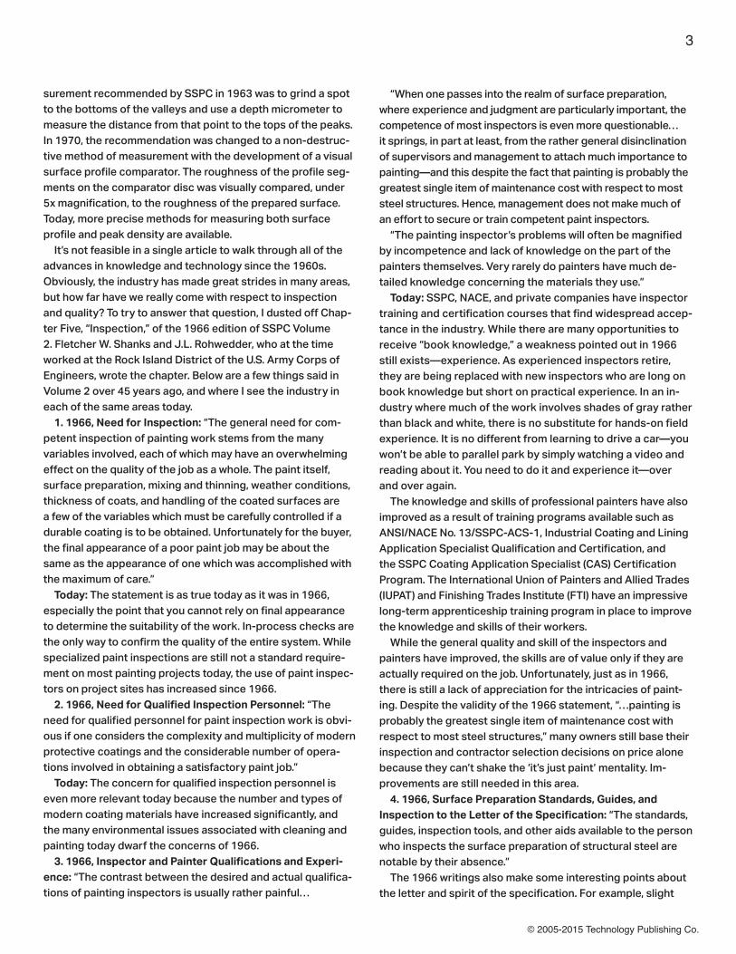
Airless spraying in 1966. While airless technology remains the same today, the industry has seen a lot of other changes since that time, including improve-ments in worker protection. How far have we come?Photo courtesy of KTA
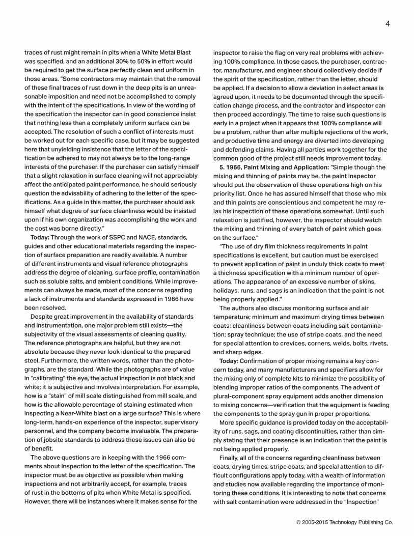
Editor’s Note: This article by Ken Trimber is part of the series of Top Thinker articles appearing in JPCL throughout 2012. Mr. Trimber is one of 24 recipients of JPCL’s 2012 Top Thinkers: The Clive Hare Honors, given for significant contributions to the protective coatings indus-try over the past decade. The award is named for Clive Hare, a 20-year contributor to JPCL who shared his encyclopedic knowledge of coatings in many forums. Profes-sional profiles of all of the award winners, as well as an article by Clive Hare, were published in a supplement to the August 2012 JPCL and in JPCL in December 2012.

© 2005-2015 Technology Publishing Co.
2
cations for various grades of surface preparation and paint materials (Fig. 1). Volume 2 included 18 different paint material specifications. Seven of the materials were based on red lead, and three were vinyl. The remainder consisted of alkyds, phenolics, and a cold-applied asphalt mastic. In addition, several paint system specifications had been developed. These specifications pack-aged all of the requirements for doing a job into a single doc-ument (e.g., surface preparation, methods of application, the individual coats required, and the thickness of each). The SSPC paint system specifications were primarily based on oil, alkyd, phenolic, vinyl, and asphaltic materials. Interestingly, three paint systems were designated as “in preparation.” One was coal tar epoxy, a great performer that has gone out of favor since that time because of health effects. The two others were epoxy and zinc (inorganic and organic), and unlike most of the other mate-rials and systems in the 1964 SSPC Volume, both have passed the test of time and are still widely used today. The specifications for hand and power tool cleaning and abrasive blast cleaning were originally developed by SSPC in 1952. They were given a complete overhaul in 1963, and Near-White Blast Cleaning was added to them. The primary speci-fications for cleaning were SSPC-SP 1, Solvent Cleaning; SP 2, Hand Tool Cleaning; SP 3, Power Tool Cleaning; SP 4, Flame Cleaning; SP 5, White Metal Blast Cleaning; SP 6, Commercial Blast Cleaning; SP 7, Brush-Off Blast Cleaning; and SP 10, Near-White Blast Cleaning. Similar to the paint material specifications, not all of the cleaning specifications survived the test of time. SSPC-SP 4, Flame Cleaning of New Steel, hasn’t been used for decades. SSPC-SP 4 required solvent cleaning in accordance with SSPC-SP 1-63, followed by passing an oxy-acetylene flame across the surface to dehydrate it and release dirt, rust, loose mill scale, and foreign matter. Immediately after the flame was applied, the surface was scraped and wire brushed to remove all loose material, and primed while it was still warm (see p. 14).
The first visual depictions of wire brushing cleanliness and the grades of blast cleaning (except for Near-White) were made available in 1963. The SSPC visual standard had actually been published by the Swedish Standards Association in 1962 (SIS 05 59 00-1962), and adopted by SSPC in 1963 as Pictorial Surface Preparation Standards for Painting Steel Surfaces, SSPC-Vis 1-63T. It was updated in 1967 to include photo-graphs consistent with a Near-White degree of cleaning and identified as SSPC-Vis 1-67T (Fig. 2). SSPC began to develop its own visual standards in the 1980s with a new SSPC version of VIS 1 published in 1989 as SSPC-VIS 1-89 (Fig. 3). The Swedish Standards were sub-sequently adopted by ISO as ISO 8501-1. SSPC went on to publish photographs of hand and power tool cleaning, water jetting, and wet abrasive blast cleaning, but SSPC changed the designations from “Standards” to “Guides and Reference Photographs.” The importance of surface profile was recognized, but the profile was typically controlled by the selection of the size of the abrasive rather than by being measured because of the complex measurement process required. The method of mea-
Fig. 1: SSPC Volumes 1 and 2 from 1966 and 1964, respectively. Photo courtesy of KTA
Fig. 2: Swedish Standards in 1967, adopted by SSPC as SSPC-Vis 1-67T. Photo courtesy of KTA
Fig. 3: First publication of SSPC’s self-prepared visual standard, SSPC-VIS 1-89, Visual Standard for Abra-sive Blast Cleaned Steel. Photo courtesy of KTA
© 2005-2015 Technology Publishing Co.
3
surement recommended by SSPC in 1963 was to grind a spot to the bottoms of the valleys and use a depth micrometer to measure the distance from that point to the tops of the peaks. In 1970, the recommendation was changed to a non-destruc-tive method of measurement with the development of a visual surface profile comparator. The roughness of the profile seg-ments on the comparator disc was visually compared, under 5x magnification, to the roughness of the prepared surface. Today, more precise methods for measuring both surface profile and peak density are available. It’s not feasible in a single article to walk through all of the advances in knowledge and technology since the 1960s. Obviously, the industry has made great strides in many areas, but how far have we really come with respect to inspection and quality? To try to answer that question, I dusted off Chap-ter Five, “Inspection,” of the 1966 edition of SSPC Volume 2. Fletcher W. Shanks and J.L. Rohwedder, who at the time worked at the Rock Island District of the U.S. Army Corps of Engineers, wrote the chapter. Below are a few things said in Volume 2 over 45 years ago, and where I see the industry in each of the same areas today. 1. 1966, Need for Inspection: “The general need for com-petent inspection of painting work stems from the many variables involved, each of which may have an overwhelming effect on the quality of the job as a whole. The paint itself, surface preparation, mixing and thinning, weather conditions, thickness of coats, and handling of the coated surfaces are a few of the variables which must be carefully controlled if a durable coating is to be obtained. Unfortunately for the buyer, the final appearance of a poor paint job may be about the same as the appearance of one which was accomplished with the maximum of care.” Today: The statement is as true today as it was in 1966, especially the point that you cannot rely on final appearance to determine the suitability of the work. In-process checks are the only way to confirm the quality of the entire system. While specialized paint inspections are still not a standard require-ment on most painting projects today, the use of paint inspec-tors on project sites has increased since 1966. 2. 1966, Need for Qualified Inspection Personnel: “The need for qualified personnel for paint inspection work is obvi-ous if one considers the complexity and multiplicity of modern protective coatings and the considerable number of opera-tions involved in obtaining a satisfactory paint job.” Today: The concern for qualified inspection personnel is even more relevant today because the number and types of modern coating materials have increased significantly, and the many environmental issues associated with cleaning and painting today dwarf the concerns of 1966. 3. 1966, Inspector and Painter Qualifications and Experi-ence: “The contrast between the desired and actual qualifica-tions of painting inspectors is usually rather painful…
“When one passes into the realm of surface preparation, where experience and judgment are particularly important, the competence of most inspectors is even more questionable…it springs, in part at least, from the rather general disinclination of supervisors and management to attach much importance to painting—and this despite the fact that painting is probably the greatest single item of maintenance cost with respect to most steel structures. Hence, management does not make much of an effort to secure or train competent paint inspectors. “The painting inspector’s problems will often be magnified by incompetence and lack of knowledge on the part of the painters themselves. Very rarely do painters have much de-tailed knowledge concerning the materials they use.” Today: SSPC, NACE, and private companies have inspector training and certification courses that find widespread accep-tance in the industry. While there are many opportunities to receive “book knowledge,” a weakness pointed out in 1966 still exists—experience. As experienced inspectors retire, they are being replaced with new inspectors who are long on book knowledge but short on practical experience. In an in-dustry where much of the work involves shades of gray rather than black and white, there is no substitute for hands-on field experience. It is no different from learning to drive a car—you won’t be able to parallel park by simply watching a video and reading about it. You need to do it and experience it—over and over again. The knowledge and skills of professional painters have also improved as a result of training programs available such as ANSI/NACE No. 13/SSPC-ACS-1, Industrial Coating and Lining Application Specialist Qualification and Certification, and the SSPC Coating Application Specialist (CAS) Certification Program. The International Union of Painters and Allied Trades (IUPAT) and Finishing Trades Institute (FTI) have an impressive long-term apprenticeship training program in place to improve the knowledge and skills of their workers. While the general quality and skill of the inspectors and painters have improved, the skills are of value only if they are actually required on the job. Unfortunately, just as in 1966, there is still a lack of appreciation for the intricacies of paint-ing. Despite the validity of the 1966 statement, “…painting is probably the greatest single item of maintenance cost with respect to most steel structures,” many owners still base their inspection and contractor selection decisions on price alone because they can’t shake the ‘it’s just paint’ mentality. Im-provements are still needed in this area. 4. 1966, Surface Preparation Standards, Guides, and Inspection to the Letter of the Specification: “The standards, guides, inspection tools, and other aids available to the person who inspects the surface preparation of structural steel are notable by their absence.” The 1966 writings also make some interesting points about the letter and spirit of the specification. For example, slight
© 2005-2015 Technology Publishing Co.
4
traces of rust might remain in pits when a White Metal Blast was specified, and an additional 30% to 50% in effort would be required to get the surface perfectly clean and uniform in those areas. “Some contractors may maintain that the removal of these final traces of rust down in the deep pits is an unrea-sonable imposition and need not be accomplished to comply with the intent of the specifications. In view of the wording of the specification the inspector can in good conscience insist that nothing less than a completely uniform surface can be accepted. The resolution of such a conflict of interests must be worked out for each specific case, but it may be suggested here that unyielding insistence that the letter of the speci-fication be adhered to may not always be to the long-range interests of the purchaser. If the purchaser can satisfy himself that a slight relaxation in surface cleaning will not appreciably affect the anticipated paint performance, he should seriously question the advisability of adhering to the letter of the spec-ifications. As a guide in this matter, the purchaser should ask himself what degree of surface cleanliness would be insisted upon if his own organization was accomplishing the work and the cost was borne directly.” Today: Through the work of SSPC and NACE, standards, guides and other educational materials regarding the inspec-tion of surface preparation are readily available. A number of different instruments and visual reference photographs address the degree of cleaning, surface profile, contamination such as soluble salts, and ambient conditions. While improve-ments can always be made, most of the concerns regarding a lack of instruments and standards expressed in 1966 have been resolved. Despite great improvement in the availability of standards and instrumentation, one major problem still exists—the subjectivity of the visual assessments of cleaning quality. The reference photographs are helpful, but they are not absolute because they never look identical to the prepared steel. Furthermore, the written words, rather than the photo-graphs, are the standard. While the photographs are of value in “calibrating” the eye, the actual inspection is not black and white; it is subjective and involves interpretation. For example, how is a “stain” of mill scale distinguished from mill scale, and how is the allowable percentage of staining estimated when inspecting a Near-White blast on a large surface? This is where long-term, hands-on experience of the inspector, supervisory personnel, and the company become invaluable. The prepara-tion of jobsite standards to address these issues can also be of benefit. The above questions are in keeping with the 1966 com-ments about inspection to the letter of the specification. The inspector must be as objective as possible when making inspections and not arbitrarily accept, for example, traces of rust in the bottoms of pits when White Metal is specified. However, there will be instances where it makes sense for the
inspector to raise the flag on very real problems with achiev-ing 100% compliance. In those cases, the purchaser, contrac-tor, manufacturer, and engineer should collectively decide if the spirit of the specification, rather than the letter, should be applied. If a decision to allow a deviation in select areas is agreed upon, it needs to be documented through the specifi-cation change process, and the contractor and inspector can then proceed accordingly. The time to raise such questions is early in a project when it appears that 100% compliance will be a problem, rather than after multiple rejections of the work, and productive time and energy are diverted into developing and defending claims. Having all parties work together for the common good of the project still needs improvement today. 5. 1966, Paint Mixing and Application: “Simple though the mixing and thinning of paints may be, the paint inspector should put the observation of these operations high on his priority list. Once he has assured himself that those who mix and thin paints are conscientious and competent he may re-lax his inspection of these operations somewhat. Until such relaxation is justified, however, the inspector should watch the mixing and thinning of every batch of paint which goes on the surface.” “The use of dry film thickness requirements in paint specifications is excellent, but caution must be exercised to prevent application of paint in unduly thick coats to meet a thickness specification with a minimum number of oper-ations. The appearance of an excessive number of skins, holidays, runs, and sags is an indication that the paint is not being properly applied.” The authors also discuss monitoring surface and air temperature; minimum and maximum drying times between coats; cleanliness between coats including salt contamina-tion; spray technique; the use of stripe coats, and the need for special attention to crevices, corners, welds, bolts, rivets, and sharp edges. Today: Confirmation of proper mixing remains a key con-cern today, and many manufacturers and specifiers allow for the mixing only of complete kits to minimize the possibility of blending improper ratios of the components. The advent of plural-component spray equipment adds another dimension to mixing concerns—verification that the equipment is feeding the components to the spray gun in proper proportions. More specific guidance is provided today on the acceptabil-ity of runs, sags, and coating discontinuities, rather than sim-ply stating that their presence is an indication that the paint is not being applied properly. Finally, all of the concerns regarding cleanliness between coats, drying times, stripe coats, and special attention to dif-ficult configurations apply today, with a wealth of information and studies now available regarding the importance of moni-toring these conditions. It is interesting to note that concerns with salt contamination were addressed in the “Inspection”

© 2005-2015 Technology Publishing Co.
5
chapter in 1966 as well as in a chapter on “Painting of Highway Bridges and Structures.” Despite this long history of concern associated with soluble salts, the detection and remediation of salts is a controversial topic today, especially the thresholds at which soluble salts are of concern when painting a structure intended for atmospheric service.6. 1966, Paint Application Inspection Equipment: “Although visual observation is the most important part of paint inspec-tion, there are some instruments and mechanical aids which will be of considerable aid to the inspector. From the stand-point that they make the painter aware that his work can be checked during progress and even after it is completed—as in the case of film thickness measurements—these inspec-tion aids can be very helpful.” The following instruments are discussed.• Consistency cup (e.g., Zahn cup)• Wet film thickness gage (wheel configuration that is rolled across the surface)• Dry film thickness gage. For field use, a magnetic flux gage based on a horseshoe magnet is discussed in the 1966 SSPC volume (Fig. 4). Magnetic pull-off (banana) gages were also used. Although standards like SSPC-PA 2 did not exist for the adjustment and use of the gages, the importance of calibrat-ing the gage on the blast-cleaned substrate and the measure-ment of the thickness above the peaks of the blast profile were addressed.• Wet sponge and high voltage holiday detectors• Tube thermometers for air temperature, material tempera-
ture, and surface temperature. It was suggested that a tube thermometer could be used to measure surface temperature by laying it on the surface, covering the end of the thermome-ter with putty to seal it to the surface and shield it from drafts, and taking a reading after it had time to stabilize. • Dry bulb/wet bulb thermometers are mentioned to calculate relative humidity, but there was no mention of dew point and its relationship to surface temperature. Note that one practice done at the time, although not addressed in the chapter, was to wipe a damp rag on the surface. If the water evaporated within a minute or two, the assumption was that the moisture conditions were acceptable and all that had to be monitored were the air and surface temperatures.• Recording hygrothermographs for relative humidity• Penetrometer for examining bituminous materials per ASTM D5, “Standard Test Method for Penetration of Bituminous Ma-terials”• A sharp knife for subjective assessment of adhesion/flexi-bility of coal tar enamel• A 5x to 10x magnifying glass and white tissue for determin-ing the amount of contamination on a surface Today: The same categories of instruments exist today, but there have been significant improvements in the technology, with electronic data collection and statistical analysis, and electronic reporting being among the latest advances. Instru-ments are available to inspect every aspect of the application process, which is good. A downside to the instrumentation, though, is that there is a general tendency to rely on digital outputs without consideration of the reasonableness of the results, especially when the results are displayed in tenths of a mil. The instruments appear to be so precise that total sam-pling error isn’t even considered when taking measurements (e.g., accuracy, precision, human error, random error, etc.). As a result, careful use and calibration of the instruments (or verifi-cation of accuracy) are more critical than ever.
ConclusionsThese are just a few comparisons of coatings work performed over 45 years ago with work performed today, but let’s revisit the original question. Are we better off? Certainly there have been significant advances in coatings technology. In most cases, the coating materials today outper-form their predecessors, and the products are certainly safer for the workers and the environment. There have also been advances in surface preparation equipment and productivity of the operations. While brush, roll, and conventional and airless spray remain the same, new spray equipment has been devel-oped to keep pace with the technology (plural-component) and to increase transfer efficiency (high-volume low-pressure). And without question, our industry is much more attuned to safety, for the painters themselves and adjacent workers, as well as for the public that may be near the worksite.
Fig. 4: This magnetic flux gage was a common instrument at the time. Photo courtesy of KTA

© 2005-2015 Technology Publishing Co.
6
Training opportunities for inspectors and painters have increased, and a wealth of research and educational mate-rials has been published to improve the understanding of how coatings work and the steps needed to optimize perfor-mance. The number and types of inspection instruments have increased to the point that essentially any step of the pro-cess can be monitored. Attempts have been made to reduce subjectivity in the assessments. But has the drive to turn the critical aspects of our work into black and white decisions created new problems for us? Have we unintentionally pushed common sense and reason aside? Has the precision of the instruments, or at least how the results are being interpreted, created additional problems for us today? For example, a common system used in 1966 involved two coats of coal tar epoxy with a total minimum thickness of 16 mils. With the instruments available at the time, you could quickly confirm that the coating was “about” 16 mils or more. Today, the instruments provide readings in tenths of a mil across the entire range of measurement. This suggests a very high degree of precision for the measurements. Assume in the coal tar epoxy example that the readings in a given area are 15.8 to 15.9 mils. Is that range acceptable? (Note that I am not muddying the water with a discussion of total sampling error or SSPC-PA 2, because even with PA 2, the question is still valid, although perhaps assigned to decisions at the 80% thickness threshold instead.) The old gages would not have even “seen” the few tenths of a mil, and the surface would have been accepted, but what about today? See Figs. 5 and 6. Many will reject the 15.8 mils of coating, but is that the right decision? First, the accuracy of both the instrument and the standards used for calibration or verification of accuracy must be taken into consideration. The surface profile can also
affect the measurements from point to point on the structure. But even assuming that all of the variables associated with sampling error are taken into consideration, and the measure-ments in an area are deemed to be 15.8 to 15.9 mils, should they be accepted? Most would argue that there is no differ-ence in performance between 15.8 mils and 16 mils, but would also agree that boundaries must be set. So from the perspec-tive of needing to have absolute boundaries, it becomes easy to reject 15.8 mils because it isn’t 16 mils. I am not offering an answer to this question but am simply pointing out that the precision of our instruments today has created controversy in areas that did not exist 45 years ago, and because of the advances in precision, one could question if we are we now unnecessarily removing and replacing coatings due to tenths of a mil, or if we are increasing project costs by adding mate-rial to an intermediate coat that appears to be slightly light, without a corresponding increase in performance? The same holds true with the measurement of surface pro-file. When requirements for surface profile shifted from simply specifying a mesh size of the abrasive to determining the profile depth with a visual comparator, the profile was typically determined within ½ to 1 mil. Today, instruments for measur-ing surface profile also provide readings in tenths of a mil. So if a specification requires the profile to be no greater than 2 mils and instrument readings range from 1.9 to 2.2 mils, is the profile acceptable? In the past, when the visual comparator was used, the profile would have been recorded as 2 mils and accepted, but what about today? See Figs. 7 and 8. First, it needs to be recognized that the surface profile is not uniform and it will vary across the surface, so accepting or rejecting a surface profile based on tenths of a mil in a given area is suspect. Further, it is unlikely that any coating
Fig. 5: The instrument used in 1966 shows a reading on a current pipe coating that would have been accepted as meeting a 16-mil minimum requirement. Photo courtesy of KTA
Fig. 6: A reading with a modern instrument on the same coating measured in Fig. 5 shows 15.8 mils. While the reading shown in Figure 5 (with the 1966 in-strument) indicates that the coating would comply with a 16-mil minimum thickness requirement, is the same conclusion reached when the coating is measured with a modern instrument? Photo courtesy of KTA

© 2005-2015 Technology Publishing Co.
7
have been satisfactorily blast cleaned, except that 25 islands of intact mill scale are found scattered across the surface. The islands measure 1⁄8 inch in diameter and therefore cover less than ½ square inch when combined. This is a clear violation of the written requirements of the specification because no mill scale is allowed to remain, but does this condition warrant the cost and time to re-blast clean the surface to address each of the small islands? Is there any room for compromise? Have we tried to become so precise in the design and implementation of painting work that our specifications and inspections are outpacing the ability of the work to comply, even under ideal circumstances? And more importantly, has fear of litigation, rather than concern for the technical aspects of the work, shaped our industry to such a point that the answer in most any dispute is to hide behind the specification and say, “It doesn’t comply, do it over.” I’ll leave you with this comment from the authors in 1966 that I quoted earlier. It was written at a time before litigation became such a sport in our industry: “As a guide in this matter, the purchaser should ask himself what degree of surface cleanliness would be insisted upon if his own organization were accomplishing the work and the cost was borne directly.” JPCL
Kenneth A. Trimber is the President of KTA-Tator, Inc., in Pittsburgh, PA, where he has been employed since
Ken Trimber in 1968
And in 2012
1968. He has more than 40 years of experience in the industri-al painting field. He is a Past President of the SSPC and serves as Chairman on SSPC Committees and Task Groups. He is an SSPC-Certified Protective Coatings Specialist, an SSPC C-3 Supervisor/Competent Person for the Deleading of Industrial Structures, and a NACE-Certified Coatings Inspector Level 3 (Peer Review).
Fig. 7: Surface profile would be reported as 2 mils using the com-parator (the surface closely matches the bottom left segment) and accepted as meeting a maximum 2-mil specification requirement. Photo courtesy of KTA
Fig. 8: The replica tape shows the profile of the same surface shown in Fig. 7 as 2.15 mils. Should this be accepted as meeting a maximum 2-mil specification requirement? Photo courtesy of KTA
manufacturer has data demonstrating that a coating system that performs over a 2-mil profile will fail at 2.1 or 2.2 mils. It is again recognized that thresholds need to be established; oth-erwise, there is no control, but should the readings be rounded to the nearest half mil, at least for some coatings? Assume that a Near-White blast is specified for a structure in atmospheric service and thousands of square feet of steel

© 2005-2015 Technology Publishing Co.
8
Quality control is an active process that needs to be a part of any protective coatings plan—from the specification stage, through surface prepa-ration and application, and after the coatings have been applied.
This should be kept in mind as we study the most recent trends in developments in quality control equipment and practices, including faster, more efficient, and ergonomically designed measurement tools, wireless digital equipment and software that cuts out all the paperwork, and thorough and decisive standards and inspection tests. The goal is to supply the contractor or inspector with the tools needed to ensure that the highest-quality quality coatings job is completed. The sampling of trends in development below is primarily based on reporting in JPCL and PaintSquare News. It is not intended to be comprehensive, and it supplements the article by War-ren Brand and the staff articles on recent SSPC standards.
Thickness Gages: In the Thick Of ItOver the past five years, the industry has seen several de-velopments in coating thickness gauges—most instrument manufacturers have either upgraded their existing thickness gauges or released new models with state-of-the-art features designed for use on a variety of substrates and industrial applications. Some of these features include built-in storage memory, high-contrast LCD display, onscreen statistics, USB mass storage, WiFi technology, and others. Software and Digital Equipment: Goodbye, Paperwork!As in just about any industry today, protective coatings quality control methods are shifting towards a more digital, comput-er-driven direction. Many new or updated thickness gages and other inspection instruments have been designed to work with new software and technology, as well. Manufacturers have released data management software that can download and upload results and images directly from the products and organize them into customized reports from which the user can easily draw conclusions. Most of this software works hand-in-hand, or is built into, the aforemen-tioned new and improved thickness gauges and other field instruments.
Inspection isn’t the only part of the quality control pro-cess that has inspired new software and technology. New cloud-based applications with features not only dedicated to coatings inspection, but also safety, time management, and accounting functions, have appeared in the market, and allow for immediate storage and analysis of results, cutting down on some of the hazards and human errors that may be involved in taking or reading measurements. Answering the call for better training in using these new technologies, in 2011, SSPC premiered a new training course, “Protective Coatings Paperless QA and Digital Data Collec-tion,” created to guide users in implementing these new digital tools and software into their work. Standards and Test Methods: Does It Pass?Of course, the measurements and numbers taken with the above tools mean nothing without context, or something to compare them to as a means of quality control. Contractors and inspectors need the most up-to-date, concise, and easily applicable standards and test methods to be able to analyze the results taken from the field. One of the most important points of reference for any indi-vidual in the coatings industry was updated in December of 2011, 16 years after its last edition. ASTM’s Paint and Coating Testing Manual: 15th Edition of the Gardner-Sward Handbook is the newest comprehensive guide to paint and coatings topics, test methods, procedures, and standards. Other Measurement Tools: Everything CountsQuality control pertains to much more than just measuring coating thickness. Like any protective coatings-related un-dertaking, there are countless factors to consider in order to ensure the highest quality possible. New quality control instruments and gauges have proliferat-ed the market, including a new soluble salt testing kit, a dolly drill adhesion tester, a dust test kit, a pre-treatment test kit, a dewpoint gauge, a surface profile and thickness gauge, a wet film comb, and a hull roughness gauge developed to test and report on corrosion and biofouling-related roughness on a ship’s hull.
By Charles Lange and Brian Goldie, JPCL Editor’s note: This article appeared in JPCL in the 2013 Special Issue
Quality Control Equipment and Practice Trends: 2009–Today

© 2005-2015 Technology Publishing Co.
9
The Quest for QC: What’s Next?Increased knowledge of the many factors dealt with during a coatings project has no doubt lead to better-trained inspec-tors performing the job, and that level of sophistication has been the influence behind the equipment developments and practice trends of the past five years. Quality control demands more, and today’s equipment has been able to provide it.
There’s no reason to think this level of sophistication will top off on the inspection end, so equipment should continue to develop hand in hand. Perhaps most importantly, though, is that these methods and equipment will be employed by better-trained, smarter inspectors and contractors—because even with all of these new technologies, quality control still needs the human touch.

© 2005-2015 Technology Publishing Co.
10
Coated concrete is a commonly used building material, and arguably can be the most likely to experience coating failures. These failures great-ly increase the potential for premature degrada-tion of the substrate material and often result in
additional expenditure of resources for repair. The good news is that such failures are far from inevitable. In many cases, the lack of a comprehensive Quality Control Procedure is at the root of coating failures. As with other build-ing materials, applying coatings to concrete requires specific measures to ensure coating performance and longevity. Assuming that the concrete surface has been determined to be sound, that it is not compromised by contaminants such as dust, oil, and grease, and that the moisture level in the con-crete is suitable for painting, the following measures should be part of a quality control program for coating application.
Surface PreparationOne of the first considerations in assuring coating quality control is the compatibility of the concrete’s physical surface texture (also known as the anchor or surface “profile”) with the coating to be applied. The recently issued ASTM standard D7682, Standard Test Method for Replication and Measurement of Concrete Surface Profiles Using Replica Putty, references both Method A (visual comparison) and Method B (quantifiable measurement) as means by which to determine concrete surface profile.
Given the possibility for coating failure and both preparation and materials costs, it may be desirable to have a permanent record of this profile for reference. One such test method that satisfies both the visual com-parison and quantifiable measurement for surface profile utilizes a rapid-cure, two-part putty. By means of application and removal of the putty, a permanent relief mold of a surface sample is obtained. The relief mold may be visually compared to ICRI (International Concrete Repair Institute) CSP (concrete surface profile) coupons or measured with a specially-built micrometer at multiple areas on the mold in accordance with the testing method.
Substrate MoistureGenerally, moisture testing should be performed before painting to determine if a problem exists. Selecting proper test methods can be challenging, however, and the specific requirements of the coating manufacturer should be imple-mented. A typical test is the plastic sheet method (described by ASTM D4263), where a plastic sheet (18 by 18 in.) is taped to the surface and allowed to remain for 16 hours. The sheet is then examined for any moisture that forms on the underside
Quality Measures: A Cure for Fear of FailureBy David Beamish, DeFelsko CorporationEditor’s note: This article appeared in JPCL in July 2012
Quality-control measurements can play a key role in ensuring proper surface preparation, substrate moisture, environmental conditions, and coating thickness and adhesion. Restoration of the exterior of Frank Lloyd Wright’s Solomon R. Guggenheim Museum, shown here, was a subject of a feature story in Journal of Architectural Coatings (now D+D) in 2009. Photo by David Heald © The Solomon R. Guggen-heim Foundation, New York
© 2005-2015 Technology Publishing Co.
11
of the plastic. If the test indicates moisture, the wall surfaces should be allowed to dry further before coatings are applied. Moisture meters may also be used, but these instruments vary widely in their ability to detect moisture within a con-crete/masonry wall. Some meters only detect moisture on the surface of the wall, but not moisture that is present within the wall (e.g. cavity or insulation). Meters that utilize radio frequency or electrical impendence have been found to offer more accuracy than others, and can determine the moisture content below the surface. Some in-struments also possess the ability to penetrate non-destruc-tively to 0.75 in. Again, the coating manufacturer should be consulted for the specific instruments to be used for moisture detection, and for the associated acceptance criteria.
Environmental ConsiderationsThe primary reason for measuring climatic conditions is to avoid rework and the premature failure of protective coatings. Recommendations and requirements are covered under vari-ous internationally recognized standards in addition to those specified by the coating manufacturer. The ability to log results may also be important as evidence of the observation of these conditions before, during, and after the coating process. Surface preparation and coating application should be performed under optimum environmental conditions to help prevent potential coating failure. A major factor affecting the long-term performance of coatings on concrete is the climatic conditions during pre-treatment and coating application. Handheld, electronic devices enable painting contractors, inspectors, and owners to measure and record applicable environmental conditions.
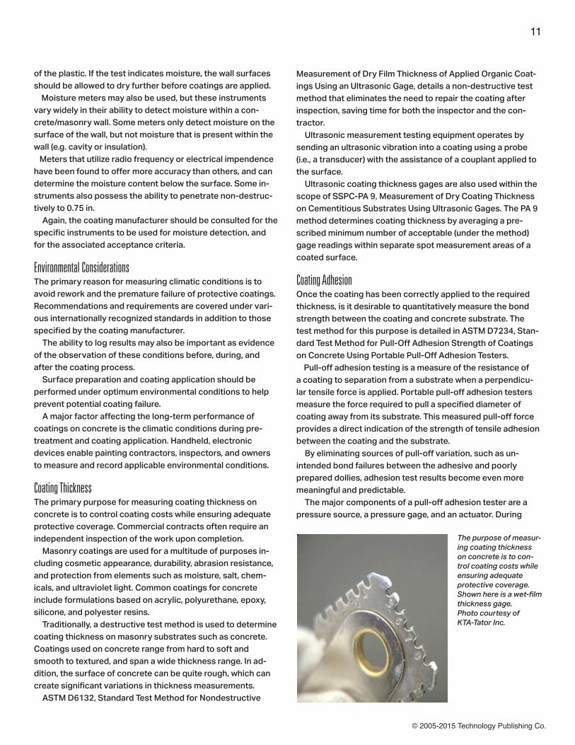
Coating ThicknessThe primary purpose for measuring coating thickness on concrete is to control coating costs while ensuring adequate protective coverage. Commercial contracts often require an independent inspection of the work upon completion. Masonry coatings are used for a multitude of purposes in-cluding cosmetic appearance, durability, abrasion resistance, and protection from elements such as moisture, salt, chem-icals, and ultraviolet light. Common coatings for concrete include formulations based on acrylic, polyurethane, epoxy, silicone, and polyester resins. Traditionally, a destructive test method is used to determine coating thickness on masonry substrates such as concrete. Coatings used on concrete range from hard to soft and smooth to textured, and span a wide thickness range. In ad-dition, the surface of concrete can be quite rough, which can create significant variations in thickness measurements. ASTM D6132, Standard Test Method for Nondestructive
Measurement of Dry Film Thickness of Applied Organic Coat-ings Using an Ultrasonic Gage, details a non-destructive test method that eliminates the need to repair the coating after inspection, saving time for both the inspector and the con-tractor. Ultrasonic measurement testing equipment operates by sending an ultrasonic vibration into a coating using a probe (i.e., a transducer) with the assistance of a couplant applied to the surface. Ultrasonic coating thickness gages are also used within the scope of SSPC-PA 9, Measurement of Dry Coating Thickness on Cementitious Substrates Using Ultrasonic Gages. The PA 9 method determines coating thickness by averaging a pre-scribed minimum number of acceptable (under the method) gage readings within separate spot measurement areas of a coated surface.
Coating AdhesionOnce the coating has been correctly applied to the required thickness, is it desirable to quantitatively measure the bond strength between the coating and concrete substrate. The test method for this purpose is detailed in ASTM D7234, Stan-dard Test Method for Pull-Off Adhesion Strength of Coatings on Concrete Using Portable Pull-Off Adhesion Testers. Pull-off adhesion testing is a measure of the resistance of a coating to separation from a substrate when a perpendicu-lar tensile force is applied. Portable pull-off adhesion testers measure the force required to pull a specified diameter of coating away from its substrate. This measured pull-off force provides a direct indication of the strength of tensile adhesion between the coating and the substrate. By eliminating sources of pull-off variation, such as un-intended bond failures between the adhesive and poorly prepared dollies, adhesion test results become even more meaningful and predictable. The major components of a pull-off adhesion tester are a pressure source, a pressure gage, and an actuator. During
The purpose of measur-ing coating thickness on concrete is to con-trol coating costs while ensuring adequate protective coverage. Shown here is a wet-film thickness gage.Photo courtesy of KTA-Tator Inc.

© 2005-2015 Technology Publishing Co.
12
operation, the flat face of a pull stub (dolly) is adhered to the coating to be evaluated. After allowing for the bonding adhesive to cure, a coupling connector from the actuator is attached to the dolly. By activating the pressure source, pres-sure is slowly increased to the actuator within the system. When testing on concrete, the pressure in the actuator typically exceeds the internal tensile strength of the concrete itself, at which point a cohesive failure occurs within the con-crete. The maximum pressure indicator of the system’s pres-sure gauge provides a direct reading of the pressure at which the pull-off occurred. With proper cutting around the dolly, the instrument can be used to measure the tensile strength of uncoated concrete, as well as concrete repairs.
QC: Key Contributor to Meeting Cost, Performance ObjectivesAs the use of concrete as a building material continues to grow, so too does the need to establish proper Quality Control
measures when applying coatings. As outlined above, these measures ensure longevity of both the coating and the under-lying structure and are a primary contributor to meeting cost and performance expectations.
David Beamish is president of DeFelsko Corp., a New York-based manufacturer of hand-held coating test instruments sold worldwide. He is a Registered Pro-fessional Engineer and has more than 25 years’ experience in the design, manu-facture, and marketing of these testing instruments in a variety of international
industries including industrial painting, quality inspection, and manufacturing. He conducts training seminars and is a mem-ber of various organizations including NACE, SSPC, ASTM, and ISO.

© 2005-2015 Technology Publishing Co.
When JPCL’s editor invited me to write a piece about changes in quality assurance and quality control (QA/QC) in the industry over the past 30 years, I was honored and motivated. I love our industry and enjoy
writing and learning as much about it as I am able to. The editor also suggested that the piece not be a “year-by-year account, but something that will be a review to veterans and an easy introduction to newcomers.” And I liked that challenge. As I was thinking about the article, my mind wandered to what was really fundamental to QA/QC for coatings. There are, of course, all the cool tools of our trade: gages, meters, electronics, comparators, etc. But I want-
ed to know what was really, really fundamental, which led me to evaluate how I work for my clients. What if I were being paid by a client to provide this type of presentation? One of the things I try to focus on in my consulting business is root-cause analysis. That is, let’s say we’ve been hired to design a coating for the inside of a sulfuric acid tank. Instead of just picking a coating system, we would also look into keep-ing moisture out of the carbon steel tank. If we could set up a dehumidification system, the tank would not actually need to be lined. A better and real-life example of looking at corrosion (which is why we’re all here in the first place) from a truly fundamental lens is the dome being built to cover the nuclear reactor at Chernobyl. As some of you might recall, Chernobyl was the single worst nuclear power reactor disaster in history. Dozens of countries contributed to the development of the “new safe confinement” (NSC). This is an unimaginably huge arch, measuring 110 meters high, 250 meters wide, and 150 meters long, and weighing in at 30,000 tonnes. The NSC is be-ing built 600 meters away from the damaged reactor and will be slid in place, over it, in 2015. The NSC is designed to last for at least 100 years and to cost an estimated $1.2 billion dollars. The arch is made of carbon steel and is hollow—in order to provide monitoring of the interstice in case there should ever be an internal breach. Well, the question was, how do you internally protect this interstice from corrosion? Painting, of course, is an option, but too dangerous in this situation, because of the proximity of deadly radiation and access. How did they solve the problem? Easy. Engineers are going to keep the interstice air-con-ditioned—through dessicant dryers—to keep the humidity
13
QA/QC: Some Things Are Old; Some Are NewBy Warren Brand, Chicago Coatings Group, LLC
Editor’s note: This article appeared in JPCL in the 2013 Special Issue
The basic processes for laying ancient floor mosaics and modern day epoxy broadcast flooring are similar; QA/QC for the mosaic was largely qualitative, while for modern flooring QA/QC is largely quantitative. iStock
Chernobyl nuclear reactor: The decision to use air conditioning instead of coatings to prevent corrosion of steel in the extraordinary dome that will protect the reactor was based on root analysis, funda-mental to QA/QC for all coating issues. iStock

© 2005-2015 Technology Publishing Co.
below 40%, below which carbon steel cannot corrode, due to the absence of the electrolyte, humidity. So in thinking about my current task of what is new, I first started thinking about what was old and what was really fun-damental to, or at the root of, all coating issues.
Way Back Then and Now: Coatings and QA/QCI thought about a video I had recently seen on the design of ancient byzantine floor mosaics. These mosaics, many of which are thousands of years old, were designed to last well, for thousands of years. They were on floors, so they were, for example, walked on, rained on, and cleaned (one presumes). And many of them are in excellent condition today. What’s different about an ancient mosaic and a modern-day floor coating application? Fundamentally, not a darn thing. The video showed that the mosaic surface, which is all we see, is actually on a bed of layered terracotta and other fill, in order to provide a sound base. This would correspond to our concrete floor or secondary containment today. Then a thick plaster of lime, plaster dust, water, and other materials was mixed and troweled onto the bed, and small pieces of glass and other durable materials were placed, by hand, into the parge coat. The plaster was designed to take a long time to cure, so that the artist would have plenty of time to place the mosaic tiles into the material. How is this different, say, from an epoxy broadcast floor system? Well, again, it’s not. In both cases we’re dealing with a solid substrate. With the mosaic, it would be a layered bed of stone with a solid parge coat. Today, the solid substrate would be our concrete floor. (We are assuming that both are new and clean.) Then, a mate-rial (today, a clear epoxy resin—then, a plaster parge coat) is applied—and aggregate placed inside the uncured material. Did the artisans and contractors thousands of years ago have the tools that we do today to conduct inspections? Of course not. Did that prevent them from successful coating applications? Same answer—of course not. But let’s look back even further, say, 40,000 years. According to a June 14, 2012 National Geographic News article (news.nationalgeographic.com), “World’s Oldest Cave Art Found—Made By Neanderthals?” there are some caves along Spain’s northern coast that contain paintings that are more than 40,000 years old—so far, the oldest in the world. Located at El Castillo, these paintings were made by some type of “mineral-based paint.” (Don’t even get me started on Roman frescoes, or ancient cisterns and viaducts that are as water-tight today as they were when they were first specified and built, by contractors wielding camel-hair brushes and wooden trowels, and wearing loin cloths, and of course, baseball caps.)
There are even products that have their ties to these same types of products used thousands of years ago. A company out of Europe has been making a product to protect and beau-tify masonry since 1878. When I was working on a project not too long ago, I asked the technical rep what the anticipated service life was, and he said something like, “I think there’s a church in Southern Italy that’s about 110 years old that’s still in good shape.” There are hundreds of similar ancient examples, but suffice it to say that we humans have been in the business of painting and coating for quite a while. After all, when the pyramids were built, they were originally lined and covered with marble. So, in looking back and obsessively thinking about this topic, I’ve concluded that, fundamentally, the only shift in the past 40,000 years has been from one of qualitative QA/QC to quantitative. That shift continues today, and, certainly, is the biggest difference in the past 30 years as well. We are simply honing our quantitative tools and training. Was there QA/QC during the time of the pyramids and before? Of course. But back then, it was, for the most part, qualitative. It was the legacy of the tradesman-apprentice relationship that maintained the quality. It was the pride one took in his work. Or, if slavery was a part of the mix, it was the fear of the repercussions for shoddy workmanship.
Not Nearly as Far Back and NowWhen I first started out in the coatings industry at 15 (1977), a gentleman named Vic Johnson worked in our company. His nickname was “Rail” because of the unusually elongated shape of his head. Vic was large and kind. (In fact, he took me to pick up my first car—an AMC Gremlin—from a junkyard when I was 16.) And Vic knew coatings as well as anyone. He
14
For the ancient pyramids, QA/QC was a matter of pride in craftman-ship or fear of retribution for poor work (or both).iStock

© 2005-2015 Technology Publishing Co.
could barely read but when it came time to abrasive blast, Vic could tell by looking and touching the surface whether or not it had the right mil-profile and correct visual appearance for proper coating. I’m certain if Vic were around today, he could tell the difference between a 1 mil profile and a 2.5 mil profile by touch. I know there are people reading this article who could do the same. So if qualitative inspection was sufficient for so many thousands of years, what’s all the fuss, rush and research per-taining to quantitative inspections? (For those seasoned folk reading this, yes, there are still qualitative aspects to some of our testing protocols, such as the use of comparators and SSPC-VIS standards) It’s about one thing, and one thing only: consistency. Today, you don’t have to have an apprentice painting con-tractor with thirty years of experience to apply a challenging tri-coat system. Because of advanced training techniques and highly effective testing tools and techniques, we can apply coatings around the world, in the most challenging of environ-ments and situations in a consistent, predictable, and quantifi-able manner. What Vic had learned from blasting millions of square feet of every material possible, we can now deduce and measure by using visual standards, comparators, replica tape, and electronic as well as mechanical gauges to determine what Vic knew in an instant. And yet, with all of our tools and training, we still get situ-ations like the Sable Offshore Energy Project in Canada. The offshore oil platform had a coating failure so profound that it was mentioned in a March 8, 2011 article on PaintSquare News (www.paintsquare.com) as, “What may be the world’s priciest botched paint job [that] could cost hundreds of millions dollars to repair.” Back in the day, when I was spraying thousands of gallons of different paints and coatings, I was able to tell, within a couple of mils, the WFT by appearance. As I applied the coating (either conventionally or airless), I could see the profile of the substrate disappear and the sheen, texture and appearance of the coating change. Of course I would use a wet mil gage to ensure my instinctual hunches, but more times than not, I was spot on. So, for beginners, I think it is critical to understand why we inspect. And for the more seasoned of us, I am hoping this was an interesting read and, perhaps, put what we do in a different perspective. So, now that we’ve established what we do (quantitative inspection protocols) and why (for consistency), let’s discuss what has changed over the past 30 years. And, in keeping with the theme of fundamentals, we’re going to talk about two dimensions: Training and Equipment. First, let me explain why we’re sticking with the fundamen-tals and painting the changes with very broad brush strokes
(pun intended). The reason is that any attempt to speak spe-cifically about either Training or Equipment will fall far short of doing either topic justice. For example, let’s take a look at the April 2013 issue of JPCL. There is an excellent and informa-tive article entitled “Measuring Dry Film Coating Thickness According to SSPC-PA 2.” The article is roughly 10 pages long and more than 4,000 words—and it’s just about checking the thickness of a coating after it has cured. The primary focus of the article is on SSPC-PA 2, the intellectual and training aspect of the duo, but, of course, it deals with the tools of our trade. But without even discussing the difference between a Type 1 gauge (magnetic or banana gauge) and a Type 2 gauge (an electronic gauge), the article goes into exquisite and appropriate detail about all of the fundamentals of testing a cured coating. So, speaking too specifically about either aspect will dilute the importance of either.
TrainingWhen I asked Pete Engelbert, a well-qualified inspector, what had changed the most in the past thirty years, he did not hes-itate: “Smarter inspectors. The biggest change has been with the level of sophistication of the inspection—not the equip-ment,” Engelbert said. Engelbert has a keen understanding of the industry, and he teaches NACE courses around the world. (His credentials include CSP, RPIH, CHST, CET, CIT, CSSM, NACE Certified Coatings Inspector—Level 3 [Nuclear/Bridge], BIRNCS Senior Nuclear Coatings Specialist #12 NACE Protective Coating Specialist, NACE Corrosion Technician, and NACE instructor.) I asked him to describe a typical inspection scenario from thirty years ago until today. So, we started with a pipe inspec-tion job (which Pete is currently handling). “Thirty years ago there were very few standards to measure conformance. Now we have multiple standards,” Engelbert said. He also said that thirty years ago during a pipe coating project, it would not be uncommon for an inspector to stand at the top of a the excavation and watch the contractor slop on some “stuff.” It would not be uncommon to have a contractor brush on petrolatum, tar, or other materials; wrap it with heavy paper; and bury it. Often, the inspector wouldn’t even look at the bottom portion of the pipe to see if it had been addressed. Surface prep wasn’t even on the radar. Today, pipes come shipped, typically, pre-coated with fu-sion-bonded epoxy (FBE). The inspector’s job is to monitor the joint coating process. Engelbert said that there are roughly 15,000 to 16,000 NACE 1 inspectors worldwide. And the demand for inspectors, par-ticularly overseas, is huge, with SSPC rapidly growing as well. “Training has taken off overseas,” he said. “The next stan-dard (for inspectors) will shift from NACE 1 to a NACE 2 or NACE 3.”
15
© 2005-2015 Technology Publishing Co.
Training and development of new standards and guidelines are universal. There are, of course, SSPC and NACE, but there are also IMO, ISO, ANSI, STI, and subsets to all of these. I am currently working on a project for a major oil company pertain-ing to CUF (corrosion under fireproofing) and related issues. There is a whole universe of guidelines, standards, nomencla-ture, and tools that are different for the CUF job than, say, a bridge coating project, even though the common denominator remains corrosion. Another broad example of improved training is SSPC’s cut-ting-edge Quality Programs (QP) and the Painting Contractor Certification Programs (PCCP). As summarized on SSPC’s website (sspc.org), the training is relevant to all aspects of a coating project.“…the selection of suitable materials is just one aspect of a successful coating project. It is critical that work is done according to sound specifications, with correct surface preparation and proper application techniques. Facility owners need to find top quality people to provide these services—trained people who know the current standards and practices and have a proven track record of success.” SSPC’s QP series is extensive and has modules for contrac-tors, owners/specifiers, and inspection companies. The trend toward smarter inspectors is profoundly obvious in the introduction to the SSPC-QP 5sm program, “Certifica-tion for Coating and Lining Inspection Companies.” “QP 5 is a certification for Inspection Companies whose focus is the in-dustrial coating and lining industry. QP 5 evaluates an inspec-tion company’s ability to provide consistent quality inspection of coatings & linings for its clients.” Engelbert said another major shift in terms of training has been documentation. Thirty years ago, there was very limited documentation and even less that was standardized. “Many of the daily forms we use today are an offshoot, a progeny, of one of the originals, which was an ANSI standard for coatings in nuclear power plants.” In fact, one of the hallmarks of the SSPC-QP certification programs is an emphasis on documentation. I think most would agree that the intellectual advances in guidelines, standards, practices, recommendations, etc., move at a relatively slow, predictable pace. That is, a two-mil profile is a two-mil profile. But not so for the tools of our trade. In con-trast, there are changes in technology that will change more in the next ten years then they’ve changed in the last 40,000.
ToolsWhen speaking with Engelbert about tools, I mentioned that I thought the biggest advance was the ability of the electronic gauges to gather and store data and then network the data directly to other devices. He laughed and quipped, “Hey, I was just happy when they came out with batteries.”
He said that thirty years ago it was unlikely to get a trained coating inspector on a job in the first place. Very often, “inspection” work was designated and assigned to an individ-ual who might be an inspector for another trade, perhaps a welder, or structural engineer. “You had welding inspectors or others signing off on coatings almost as an afterthought.” He said if a job was fortunate enough to have a coating inspector on site, and he was tasked, say, to measure DFTs, “You’d have one inspector taking measurements with a ba-nana gauge and another walking behind him with a clipboard taking notes.” Now, modern gauges can store almost limitless inspection points and then download them for evaluation. “Fundamentally, it means the inspector has to get smarter. You have to know how to use a computer and, if you don’t, find an eight-year-old to teach you,” he said.
Suffice it to say that the fundamental focus of inspection tools in the past thirty years has been in ease of use, storage capac-ity, and data sharing (USB, Blue-Tooth, wireless), etc. But the most exciting and most important advances are the cutting edge developments we are seeing now. The breadth is breathtaking. I attended a conference about eight years ago in conjunction with the National Center for Manufacturing Sciences (NCMS). One of the latest (at the time) technologies for surface preparation of aircraft was the use of lasers to remove paint. With wings being designed to unimaginable tolerances, the use of an abrasive was impossible because it might damage or warp the wing. The typical means of paint removal was through highly toxic and dangerous paint remov-ers, oftentimes methylene chloride. The technology was in its infancy at the time but is now being widely used to remove paint from aircrafts. Then there’s a November 30, 2011 article from the United States Naval Research Laboratory entitled, “NRL Researchers Develop ‘Streamlined’ Approach To Shipboard Inspection
16
The introduction and continuing development of digital equipment for QA/QC has dramatically changed quantitative inspection of coatings. “Smart” technology meets today’s smart inspectors, who have bene-fitted from QA/QC training, certification, and standards not available 30 years ago. iStock

© 2005-2015 Technology Publishing Co.
Process” (http://www.nrl.navy.mil/media/news-releases/2011). The article talks about inspecting the condition of exterior shipboard coatings. In the case study reported, the work was performed on the USS Aircraft Carrier, the Nimitz. In a quote from the article, “The manual method required a 65-man-day effort to perform the inspection of the entire topside coating with results taking an additional four weeks to complete. By contrast, we were able to perform the same inspection using digital hand-held cameras with the new process in less than four days including immediate access to over 3,000 images depicting the ship’s surface condition for in-depth inspection.” Briefly, the new process includes highly-detailed photo-graphs downloaded and analyzed by algorithms used to quan-tify the condition of the existing coating. Going even a step further, we haven’t even touched upon the changing technologies pertaining to coatings and how those changes will interact with, and change, technologies for inspection services. For example, it is not uncommon to use a conductive primer on concrete in order to be able to use a holiday detector on the subsequent topcoat. There are talks of nanoparticles that
may communicate with various devices, the use of fluorescent additives to indicate DFT, etc.
ConclusionAre we far from the day when new coating systems will work in concert with new technologies to speed and improve our ability to quantify and control coating applications? “I am working with an engineering company that is develop-ing a visor that, using different light frequencies, can see the depth of profile, DFTs, number of coats, wet and dry. After that, who knows? A paint ball gun that could paint an entire water tower tank? It’s only a matter of time,” said Mr. Engelbert.
Warren Brand is the founder of Chicago Coat-ings Group, LLC, a consulting firm he formed in 2012. Before opening his consultancy, Brand was the president of Chicago Tank Lin-ings. He has more than 25 years of experience as a coatings contractor, is an SSPC-cer-tified Protective Coatings Specialist and a NACE-certified Level 3 coatings inspector, and holds an MBA and a BA in Journalism. JPCL
17

© 2005-2015 Technology Publishing Co.
Every painting project begins with the expectation that the result will be a painted structure that will be protected for a minimum period of time. Owners rely on tools such as the specifications, contractor certification, quality control, and quality assurance
inspection to verify that the work is performed as specified. While many projects require quality control and/or quality assurance inspections, few specifications, if any, differentiate between the two or provide guidance on the responsibilities of each. After discussing the difference between the functions of quality control and quality assurance, this article reviews the SSPC certification program requirements, other recognized industry standards, and transportation specifications that establish minimum standards of practice for quality control and quality assurance. It concludes with recommendations for maximizing the benefits of both quality control and quality assurance.
Evolution of QC and QA in the Coatings IndustryWhen the coatings inspection industry began to evolve in the 1970s, there was little distinction between the roles of QC and QA. Most early coating inspection was performed as a response to the inspection parameters established in the nuclear power industry and ANSI/ASME N45.2.6, “Qualification of Inspection, Examination and Testing Personnel for Con-struction Phase of Nuclear Power Plants,” and ANSI N101.4, “Quality Assurance for Protective Coatings Applied to Nuclear
Facilities.” These standards defined the qualifications of coat-ings inspectors and inspection tasks that were required during installation or maintenance of nuclear power facilities. ANSI N45.2.6 specifically applied to third-party inspectors retained by the owner to perform hold point inspection of contractor activities. As coating inspection expanded beyond nuclear power into industries like transportation and water storage and supply, most owners continued to rely on third-party inspection to verify that contractor activities were per formed according to the specification. In the 1990s and 2000s, with the increased recognition of the International Organization for Standardization (ISO), Ameri-can Society of Quality (ASQ), and other certifying organiza-tions, more owners, consultants, and contractors started mov-ing to the concept of a total quality system with a clear division between QC, conducted by the contractor, and QA, conducted by the owner or a third-party owner’s representatives. Owners began to recognize that while third-party inspection was still necessary, it was not intended to replace the contractor’s QC. Unfortunately, this awareness has not always been been transferred to the specifications as particular QC require-ments. The result is that QA personnel still perform the prima-ry role of inspecting and accepting the work. When the roles of QC and QA personnel are not defined, a critical component of a total quality system is lost, and conflict can arise between QA and contractor personnel. But when the QC and QA per-sonnel perform their respective tasks during coating system installation, the end product improves.
18
By Alison B. Kaelin, Corporate Quality Assurance Manager, KTA - Tator, Inc., Pittsburgh, PA, USA
Editor’s note: This article appeared in JPCL in April 2005
When it comes to quality, people sometimes disagree...
Quality Control and Quality Assurance:Defining the Roles
and Responsibilities
of the Contractor’s QC
and the Owner’s QACourtesy of KTA-Tator
© 2005-2015 Technology Publishing Co.
QA vs. QC: What’s the Difference, Anyway?Quality Control is performing the necessary observations, testing, and documentation to verify that the work performed meets or exceeds the minimum standards established by the project specifications or contract. QC is the contractor’s responsibility. Quality Assurance is an audit process to verify that the quality of work performed is what was inspected and reported by the contractor’s QC. QA is conducted by the owner or by a third party inspector on the owner’s behalf. QA may include reviewing QC documentation, observation of QC testing or actual testing on a spot or periodic basis. Basically, then, the contractor is fully responsible for every aspect of the project from the equipment and materials, and experience and training of personnel, to the quality of the final product. QC is a full-time requirement and has responsibili-ties for every aspect of the surface preparation and painting process. QA can be full- or part-time, or performed at specific stages (e.g., following surface preparation) of the project to
verify the adequacy of the contractor’s QC. When the owner does not perform QA or provides limited QA inspection, half of the total quality management process is lost. Both QC and QA are necessary to verify specification com-pliance and quality work, but an owner (or third-party inspec-tor) performing QA on a project does not relieve the contrac-tor of the responsibility of performing QC.
Control of Work: A Critical DifferenceOnly the contractor’s QC person has the authority to direct the contractor’s employees or production operations. When a contractor is required to retain a third-party QC representa-tive, that person is not a direct employee of the contractor and may not have the authority to direct the contractor’s workers or ensure that they correct their work when needed. Similarly, limitations may be found when the owner requires the coating manufacturer’s technical representative to perform QC func-tions: there is no contractual relationship; observations may not be free of bias; conflicts between the manufacturer and
19
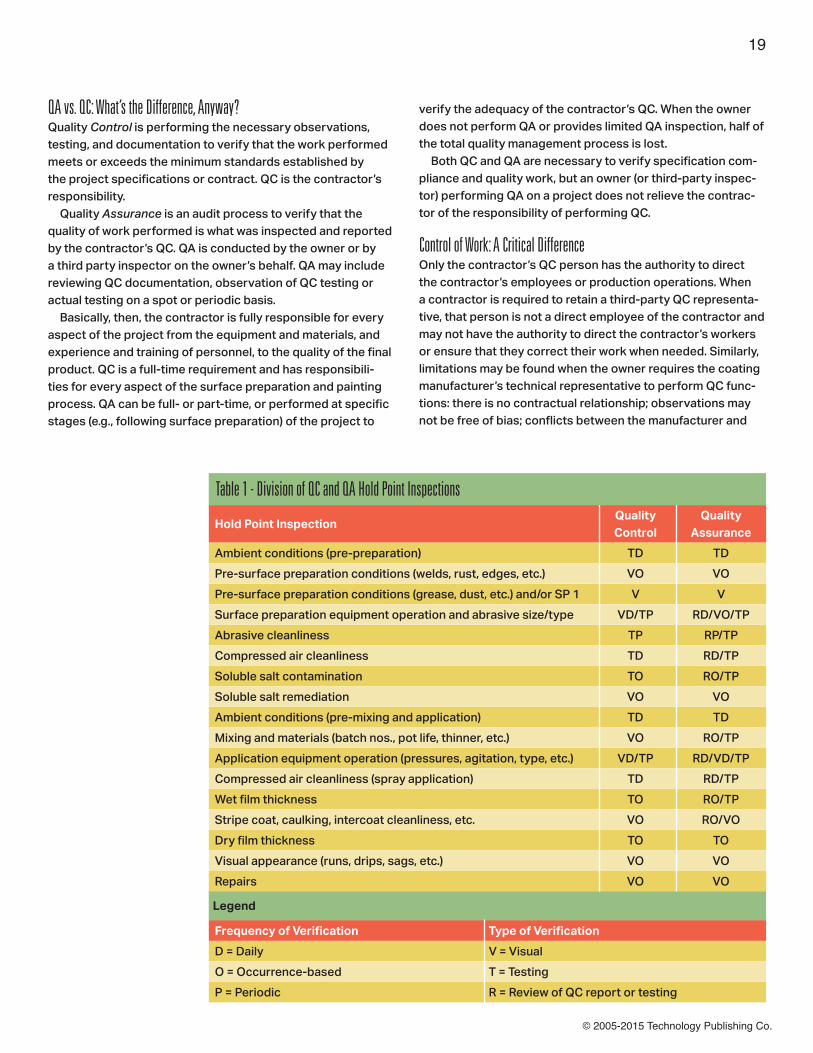
Hold Point InspectionQuality Control
Quality Assurance
Ambient conditions (pre-preparation) TD TD
Pre-surface preparation conditions (welds, rust, edges, etc.) VO VO
Pre-surface preparation conditions (grease, dust, etc.) and/or SP 1 V V
Surface preparation equipment operation and abrasive size/type VD/TP RD/VO/TP
Abrasive cleanliness TP RP/TP
Compressed air cleanliness TD RD/TP
Soluble salt contamination TO RO/TP
Soluble salt remediation VO VO
Ambient conditions (pre-mixing and application) TD TD
Mixing and materials (batch nos., pot life, thinner, etc.) VO RO/TP
Application equipment operation (pressures, agitation, type, etc.) VD/TP RD/VD/TP
Compressed air cleanliness (spray application) TD RD/TP
Wet film thickness TO RO/TP
Stripe coat, caulking, intercoat cleanliness, etc. VO RO/VO
Dry film thickness TO TO
Visual appearance (runs, drips, sags, etc.) VO VO
Repairs VO VO
Legend
Frequency of Verification Type of Verification
D = Daily V = Visual
O = Occurrence-based T = Testing
P = Periodic R = Review of QC report or testing
Table 1 - Division of QC and QA Hold Point Inspections
© 2005-2015 Technology Publishing Co.
contractor may result; and neither QC nor QA is provided. But when the owner’s staff performs QA (with direct staff), the owner has a contractual relationship with the contractor, and therefore can exert control through the contract (or by withholding payment or stopping work) when operations or conditions are non-conforming. Third-party QA subcontracted to the owner does not have a contractual relationship with the contractor; therefore, the third-party QA inspector typically can only document the non-conformance of the contractor’s operations and advise the contractor or the owner. If the contractor fails to correct the non-conformance, the owner must decide whether to stop work, withhold payment, accept the non-conformance or take other action. But whoever performs QA must be careful not to direct or unduly interrupt contractor operations due to potential con-
tract issues regarding control of the work and costs related to work stoppages.
Sequence of QC and QA The specific duties of QC and the QA personnel will vary from project to project. The coating inspection process typically dictates that after certain activities (e.g., surface preparation), work should be inspected, rework performed as necessary, and the surfaces accepted by QC and QA staff before the contractor can move on to the next step of the project. These specific inspection items are typically referred to as “hold points” (Table 1). Generally, the QC inspection of each hold point should occur first, and any non-conforming items identified should be corrected, re-inspected and accepted by the QC inspec-
20
Other Organizations that Define QC and QA Responsibilities
NACEThe NACE International Coating Inspection Program (CIP) began certifying coatings inspectors over 20 years ago. The CIP establishes three levels of certification for individual coatings inspectors (regardless of whether they perform QC or QA). The NACE training provides a comprehensive review of the observations, tests and examinations that may be performed by a coating inspector during the coating process but does not define them relative to QC and QA. The student manual for Session 1 (7/1/98), The Coating Inspector’s Checklist, indicates inspection tasks ranging from pre-surface preparation to coating application.
ANSI/ASMEANSI/ASME N45.2.6, Qualification of Inspection, Examination and Testing Personnel for Construction Phase of Nuclear Power Plants, establishes criteria for companies to internally certify individual coatings inspectors through experience, education, and testing as Level I, II, or III coating inspectors. The SSPC-QP 5 standard adopted thelevels used by ANSI/ASME N45.2.6.
ASTM InternationalASTM International has several standards that discuss coating inspectors and responsibilities but without differentiating between QC and QA. ASTM standards discussing inspector responsibilities or Other Organizations that Define QC and QA Responsibilities inspection and inspection activities related to applicator certification include the following:• D 4227-99, Standard Practice for Qualification of Coating Applicators for Application of Coatings to Concrete Surfaces;• D 6237-98, Standard Guide for Painting Inspectors (Concrete and Masonry Substrates);• D 4228-99, Standard Practice for Qualification of Coating Applicators for Application of Coatings to Steel Surfaces;• D 3276-00, Standard Guide for Painting Inspectors (Metal Substrates);• D 5161-04, Standard Guide for Specifying Inspection Requirements for Coating and Lining Work (Metal Substrates); and• D 4537, Establishing Procedures to Qualify and Certify Personnel Performing Coating Work Inspection in Nuclear Facilities.
Painting and Decorating Contractors of America (PDCA) PDCA has three specifications that address inspection: • P2-92, Third Party Inspection Qualification and Responsibilities;• PDCA P4, 94, Responsibilities for Inspection and Acceptance of Surfaces Prior to Painting and Decorating; and• PDCA P8-00, Owner’s Responsibility for Maintenance of Paints and/or Coatings. None of the PDCA documents address the specific division of QC and QA responsibilities.
Continued on page 22
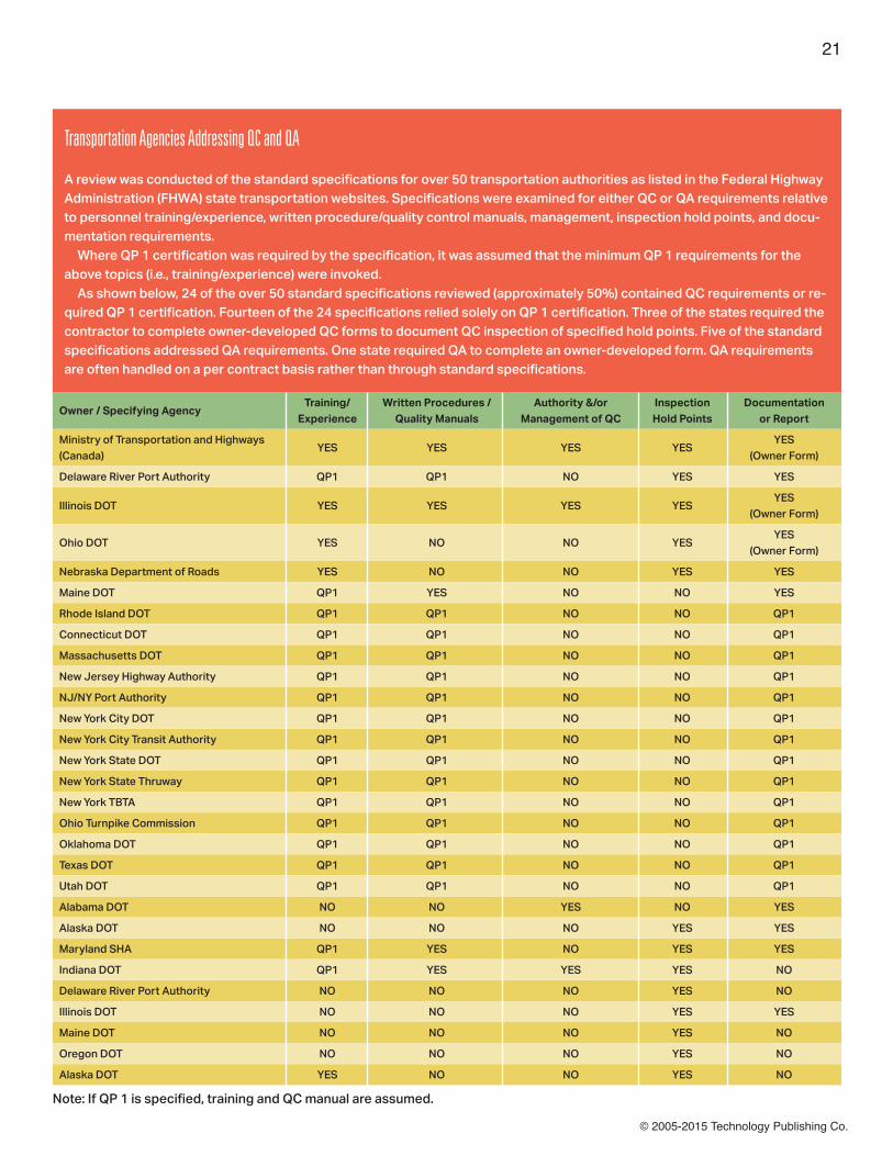
© 2005-2015 Technology Publishing Co.
21
Owner / Specifying AgencyTraining/
ExperienceWritten Procedures /
Quality ManualsAuthority &/or
Management of QCInspection Hold Points
Documentation or Report
Ministry of Transportation and Highways (Canada)
YES YES YES YESYES
(Owner Form)
Delaware River Port Authority QP1 QP1 NO YES YES
Illinois DOT YES YES YES YESYES
(Owner Form)
Ohio DOT YES NO NO YESYES
(Owner Form)
Nebraska Department of Roads YES NO NO YES YES
Maine DOT QP1 YES NO NO YES
Rhode Island DOT QP1 QP1 NO NO QP1
Connecticut DOT QP1 QP1 NO NO QP1
Massachusetts DOT QP1 QP1 NO NO QP1
New Jersey Highway Authority QP1 QP1 NO NO QP1
NJ/NY Port Authority QP1 QP1 NO NO QP1
New York City DOT QP1 QP1 NO NO QP1
New York City Transit Authority QP1 QP1 NO NO QP1
New York State DOT QP1 QP1 NO NO QP1
New York State Thruway QP1 QP1 NO NO QP1
New York TBTA QP1 QP1 NO NO QP1
Ohio Turnpike Commission QP1 QP1 NO NO QP1
Oklahoma DOT QP1 QP1 NO NO QP1
Texas DOT QP1 QP1 NO NO QP1
Utah DOT QP1 QP1 NO NO QP1
Alabama DOT NO NO YES NO YES
Alaska DOT NO NO NO YES YES
Maryland SHA QP1 YES NO YES YES
Indiana DOT QP1 YES YES YES NO
Delaware River Port Authority NO NO NO YES NO
Illinois DOT NO NO NO YES YES
Maine DOT NO NO NO YES NO
Oregon DOT NO NO NO YES NO
Alaska DOT YES NO NO YES NO
Note: If QP 1 is specified, training and QC manual are assumed.
Transportation Agencies Addressing QC and QA
A review was conducted of the standard specifications for over 50 transportation authorities as listed in the Federal Highway Administration (FHWA) state transportation websites. Specifications were examined for either QC or QA requirements relative to personnel training/experience, written procedure/quality control manuals, management, inspection hold points, and docu-mentation requirements. Where QP 1 certification was required by the specification, it was assumed that the minimum QP 1 requirements for the above topics (i.e., training/experience) were invoked. As shown below, 24 of the over 50 standard specifications reviewed (approximately 50%) contained QC requirements or re-quired QP 1 certification. Fourteen of the 24 specifications relied solely on QP 1 certification. Three of the states required the contractor to complete owner-developed QC forms to document QC inspection of specified hold points. Five of the standard specifications addressed QA requirements. One state required QA to complete an owner-developed form. QA requirements are often handled on a per contract basis rather than through standard specifications.

© 2005-2015 Technology Publishing Co.
tor. The QA inspection should only occur after the work (hold point) has been inspected and accepted by the QC inspector. The QA inspector should then verify that the work that the QC inspector accepted meets the requirements of the specifi-cation. If the QA inspector identifies non-conforming items, they should be repaired and reinspected by the QC inspector before the QA inspector accepts the work and the contrac-tor proceeds to the next step of the painting process. It is often helpful, if not necessary, to have the QC inspector and the foreman present during the QA observations so that any deficiencies can be identified and confirmed by all parties. This also allows the QC inspector and the foreman to clearly identify areas requiring rework to the laborers and reduces production delays. The QA observations may include a review of the contrac-tor’s QC tests or documentation and duplicate inspection or testing of certain hold points (e.g., dry film thickness measure-ments) to verify that the contractor’s reported results reflect the quality of the work. When results of QC and QA inspection differ, the QA obser-vations typically supersede those of the QC. The resolution of differing QC and QA observations should be defined in the project specification or agreed upon by all stake-holders in the pre-job meeting.
SSPC ’s Approach to QC and QA SSPC: The Society for Protective Coatings (SSPC) has estab-lished four qualification procedures (QP) for contractors that include minimum requirements for QC. • SSPC-QP-1, “Standard Procedure for Evaluating Qualifica-tions of Painting Contractors (Field Application to Complex Structures),” establishes specific requirements for the quali-fications and duties of the contractor’s QC personnel on field coating application projects. • Three other standards have similar requirements: QP 3, “Standard Procedure for Evaluating Qualifications of Shop Painting Applicators”; QP 8, “Standard Procedure for Evaluat-ing the Qualifications of Contracting Firms that Install Polymer Coatings and Surfacings on Concrete and Other Cementitious Substrates”; and QP 6, “Standard Procedure for Evaluating the Qualifications of Contractors Who Apply Thermal Spray (Metallizing) for Corrosion Protection to Steel and Concrete Surfaces.” QP 6 requires QP 1 or QP 3 certification, also. Each standard above identifies minimum requirements for quality control personnel, programs, inspections, and docu-mentation. The following provides a brief review by key topic. While the specific QC duties are not well defined in the SSPC-QP standards, the supporting documentation required by the respective standards sometimes provides additional insight on the requirements for the contractor’s QC. Minimum QC Qualifications: Under QP 1 and QP 3, the QC supervisor is responsible for oversight of the QC inspectors.
The QC supervisor is required to have three to five years of experience and formal training. The QC inspector is to have a minimum of two years of experience and formal training for QP 1; however, QP 3 allows the QC inspector to substitute in-house training for formal training. QP 8 requires the QC manager and QC inspectors to have two years of experience, 8 hours of general QC training, and 16 hours of concrete training. QP 6 refers to the thermal spray supervisor (TSS) and thermal spray inspector (TSI) rather than QC. It requires the TSS to have minimum of two years of experience and quali-fication under internal programs. The TSI must be internally qualified to perform thermal spray inspections. There is no established curriculum, duration, or evaluation of knowledge or practical testing required under the QP 1 and QP 3 standards. Refresher training is not required by any QP standards. Written Procedures/Quality Manuals: QP 1 requires the contractor to have written procedures to ensure that major operations (surface preparation; primer, intermediate, and top coat applications) are inspected. It suggests that these procedures are components of a “QC Manual.” QP 3 simply requires the QC to have relevant inspection standards. QP 8 specifically details standard operating procedures that must be included in the contractor’s QC manual. QP 6 requires the contractor to have formal written procedures for performing and documenting inspections. Authority of the QC/Management: QP 1 requires written au-thority for the QC inspectors to report directly to management and have to have authority to stop work for non-conformanc-es. QP 3 is similar but requires evidence that the QC inspector reports directly to management, not to a production-related supervisor or manager. QP 8 and QP 6 do not define the authority of the QC. QP 6 requires the TSS to be onsite and involved in material and equipment decisions. QC Inspection Hold Points: QP 1 does not define the specif-ic hold points for QC. However, the SSPC-QP 1 Annual Internal Audit Report/Checklist for SSPC Certified Contractors (Rev 02/04) indicates that hold point inspections are to be con-ducted during each major operation: pre-cleaning, surface preparation, primer, intermediate coat, topcoat application, and cure. QP 3 defines hold points for receipt of items to be coated, inspection of repaired and coated items, storage of repaired and coated items, surface preparation, storage of coating ma-terials, handling, repair, labeling, and handling and shipment, among others. QP 8 requires hold point inspections based upon the de-tailed requirements of the QC plan. QP 6 requires hold point inspection for major operations defined in the written proce-dures. Documentation/Report: QP 1 does not define the informa-tion that must be documented in QC. The SSPC-QP 1 Annual
22

© 2005-2015 Technology Publishing Co.
Internal Audit Report/Checklist, specifically requires that daily QC reports be prepared to include information such as com-pressed air cleanliness, dry film thickness, air temperature, humidity, dew point, surface temperature, abrasive cleanli-ness, degree of cleanliness achieved, surface profile, batch numbers of paint and thinner used, and mixing according to specification. QP 3 provides a similar list; however, it adds wet film thick-ness and the type and amount of thinner used. QP 6 and QP 8 do not define the information to be recorded other than references to the QP program requirements. SSPC has indicated that it will review all QP procedures and auditing discrepancies for resolution in 2005.
New Quality Standard from SSPC Supplements the QC StandardSSPC has prepared SSPC-QS 1, Standard Procedure for Evalu-ating a Quality Standard of Contractors That Apply Protective
Coatings and Linings, for the 2005 SSPC Volume 2, Systems and Specifications. It provides a supplemental standard (QS 1) for use by owners that require a higher level of QC on projects than is addressed in the QP standards. This standard must be specified in addition to the applicable QP standard. QS 1 sets out minimum QC qualifications; requires implementation of a quality system rather than a QC manual; calls for docu-mentation of training of managerial staff and demonstrated management review of fieldwork and QC documentation; recommends that the contractor provide a project-specific work plan defining the inspections, reference standards, and documentation; and requires that results of all inspections and tests be recorded in a written report. QS 1 also introduces requirements that are not included in the QP standards for contractors, including an annual written review of the QC manual by the QC manager; periodic internal review of QC documentation by the QC manager; and a policy
23
RecommendationsWe all can improve our understanding of the functions of quality assurance and quality control. Owners, for example, should evaluate and revise current standard specifications, special provisions, and contracts (i.e., contractor and owner or third-party inspection) to clearly define the responsibilities of QC and QA personnel. Owners also should require adequate QC coverage based on projected schedules or minimum QC coverage by crew, struc-ture, location, or working hours. And owners should require QC personnel to meet minimum standards of training and experience, provide QC procedures, and maintain documentation that will be used to verify the quality of the final product. Furthermore, when specifying SSPC or similar certifications, owners should require the contractor to provide evidence of QC personnel qualifications and training, necessary QCequipment, QC procedures, and the type of documentation to be completed by the QC inspector. QS 1 should be required in addition to QP certifications. Owners also should develop QC forms or require the QC to use industry - recognized forms. Similarly, owners should devel-op QA forms for use by internal QA or third party QA. Finally, owners should evaluate QA coverage based on the contractor’s proposed work plan, number of crews, locations, or working hours. Contractors must recognize that QC is the first step in the total quality process and that adequate employee training, expe-rience, and adherence to QC procedures and documentation are crucial. In addition, contractors should provide for adequate level of QC in the project estimate and bids. Third-party inspection agencies need to clarify in advance with owners and contractors the sequence of QC and QA in-spections, how to resolve conflicts, and how to communicate non-conforming conditions. Third-party inspectors also must verify whether the scope of the inspection is quality control or quality assurance. They must clarify QA inspection hold points versus QC responsibilities. Trade organizations, such as SSPC, NACE, PDCA, and ASTM, should evaluate the appropriate qualifications/experience, inspection, and documentations specific to QC and QA in their standards. Such organizations should also consider annual retraining, minimum training curriculum or training hours, or certifications for QC personnel. SSPC should evaluate its certification programs for consistency among the different QP standards. Consideration should be given to defining minimum training requirements for QC and management of the QC process similar to the approach used for QP 5-certified inspection companies. Some of the actions planned for this year appear to indicate that SSPC is moving in this direction. FHWA/AASHTO should consider developing master guidelines and specifications relative to the QC and QA on transporta-tion projects .

© 2005-2015 Technology Publishing Co.
to address the investigation, auditing, and resolution of client complaints.
SSPC Qualification Procedures for Quality Assurance SSPC has one QP applicable to QA: SSPC-QP 5, “Standard Procedure for Evaluating Qualifications of Coating and Lining Inspection Companies.” The SSPC-QP 5 program establishes a certification for inspection companies whose focus is the industrial coating and lining industry. It evaluates an inspec-tion company’s ability to provide consistent quality inspection of coatings and linings for its clients (typically third-party QA). Like the portions of the SSPC-QP certifications relat ed to QC, QP 5 provides minimum requirements for quality assurance personnel, programs, inspections and documentation. The new QS 1 incorporates many QP 5 requirements. Minimum QA Qualifications: QP 5 requires the company to employ a total quality manager (TQM) who reports directly to management. The TQM must have at least 10 years of experi-ence and be an SSPC PCS or NACE-Certified Coating Inspec-tor or must hold a BS degree in corrosion science or engineer-ing. Inspectors employed by a QP 5-certified company are divided into three levels of responsibility, based primarily upon experience and education. In addition to coating inspection training, QP 5 requires QA inspectors to undergo annual vision testing and a coating inspection refresher training. Written Procedures/Quality Manuals: QP 5 requires partici-pants to develop a complete quality system that addresses:• quality policy and management commitments;• organizational, management structure, and reporting rela-tionships;• procedures for performing coating inspections and tests;• references to inspection equipment, calibration, mainte-nance, and measurement standards; and• internal audit procedures and schedule. The program must be reviewed annually and documented by a written report to management. Management of QA: QP 5 requires the TQM to audit the QA inspection staff and oversee the implementation of the quality system. In addition, QP 5 requires participants to train auditors and audit the implementation of the quality system. QP 5 does not define QA hold points or documentation requirements, but states that they are dictated by contract. QP 5 places several additional requirements on QA that are not included in contractor QP programs, such as internal audits, internal review of QA reports, and resolution of client complaints.
Staffing of QC and QA Personnel The contractor’s schedule, number of work crews or locations, the QC’s other responsibilities, and adequate staffing for QC and QA can also have a significant impact on QC and QA work.
Under the SSPC certification requirements, while the contractor is required to provide a QC representative, there is no guidance on the number of QC personnel or QC time necessary to achieve adequate quality control. For projects involving multiple structures or locations, or multiple crews, it is unlikely that a single QC inspector could perform the neces-sary observations, testing, and documentation to verify that all the work was performed as required by the project spec-ification or the respective QP standard. If the QC inspector is performing additional duties (e.g., acting as the competent person or assisting in production operations), his or her ability to adequately perform QC is further compromised. None of the QP requirements prevent the QC from performing other functions. Where there is inadequate QC coverage of the key hold points, the QA inspector may be the only one performing ob-servations and testing. This results in the loss of the primary component (quality control) of the total quality management system. It can also lead to confrontation between the con-tractor and the QA inspector when non-conformances are observed and the QC inspector was not involved in the initial inspection and correction of the work. Inadequate QA staffing can also result in inadequate quality auditing of the QC. The level of QA inspection and the number of assigned staff are typically established by the owner based on an engineer’s estimate of the project schedule and con-tractor’s labor. However, once a contractor has been selected, the contractor typically dictates the schedule, number of work crews, work areas, and working hours. The QA staffing plan should be carefully evaluated against the contractor’s actual schedule to see if adequate QA staff is available. Another potential problem with QA staffing is that with shrinking painting budgets, often QA time on-site is limited by the project budget. QA may be limited to an eight-hour workday, while actual contractor operations occur for 12 to 14 hours per day during peak periods. As most of the coating work is performed at the end of the day, a QA inspector may not be on-site during the mixing and application of the coat-ing. A reasonable rule of thumb is that the QC and QA should be present for the complete workday or week. When QA staffing is inadequate, the ability to observe all operations is compromised. In the absence of effective QC, valuable QA time is lost performing initial inspections.
Separating QC and QA ResponsibilitiesQualifications: QC qualifications appear to be inconsistently defined in most of the documents researched. Since QC has the primary responsibility for the quality of the end product, QC personnel should have a minimum level of experience and formal training to perform and document the implementation of the QC process. Consideration should be given to requiring QC personnel to document proficiency in coating inspection
24

© 2005-2015 Technology Publishing Co.
through formal certification or successful completion of a specific curriculum. When SSPC-QP 1 is specified, the experience and training of the proposed QC should be verified. • Procedures: Similar to the above, the contractor should be required to follow written QC procedures and maintain docu-mentation for recording the QC observations. Most specifica-tions reviewed did not specify submission of QA procedures. Documentation was required for most QA inspections.• Hold Points: This article suggests that the QC has full-time responsibility for all phases of the project. Further, given the contractor’s control of the equipment, personnel, material, and processes, they must, through QC, be responsible for testing of its operation and adequacy. QA is typically specified at critical hold points and for periodic verification that the QC is being implemented. An appropriate division of hold points between QC and QA is delineated in Table 1 on p. 59. Appropriate division of hold point inspections of the QC and QA personnel should result in the ultimate responsibility for quality being that of the contractors, and should allow QA inspectors to fulfill their role as an audit function, rather than as the sole entity responsible for the quality of a coatings project.
ConclusionOnly by establishing clear qualifications, responsibilities, and documentation requirements for both QC and QA on a given project will all parties to a protective coatings project benefit fully from a total quality management process. Benefits can include avoiding duplication of documentation and inspection, reducing conflicts among the contractor, owner, and third par-ty QA; real or perceived under- or over-inspection; and most importantly, long-lasting protection of the structure or asset.
Alison B. Kaelin is the KTA corporate quality assurance manager and former manag-er of the KTA Environmental Health and Safety Group. She holds a BE in civil and environmental engineering from Vanderbilt University and is a NACE-certified coatings inspector. Ms. Kaelin also has 17 years of
public health and environmental experience. She chaired the SSPC Task Group C.5.3 on Environmental Monitoring Strat-egies and the Dust Collection Committee, and is a principal instructor of SSPC’s C-3 Certified Supervisor/Competent Person for Industrial Deleading Projects. Ms. Kaelin has presented and published over 15 articles on environmental protection, worker health and safety, and other topics related to the coatings industry.
25

© 2005-2015 Technology Publishing Co.
26
For decades we have heard that the incidence of premature coating failure would decline by explic-itly requiring the contractor to control the quality of workmanship (via contract document language) using properly trained (and equipped) quality
control personnel. In this Case from the F-Files, we’ll take a brief look at five case history failures and assess whether quality control inspection of the work as it proceeded could have prevented the failure from occurring, or whether it would have happened despite the efforts of knowledgeable quality control personnel.
Defining Quality ControlThe ISO definition states that quality control is the operational techniques and activities that are used to fulfill requirements for quality.1 This definition could imply that any activity, whether serving the improvement, control, management, or assurance of quality could be a quality control activity. Quality control is a process for maintaining standards and not for creating them. Standards are maintained through a process of selection, measurement, and correction of work, so only the products or services that emerge from the process meet the standards. In simple terms, quality control prevents undesir-able changes in the quality of the product or service supplied. The simplest form of quality control is illustrated in Fig. 1. Quality control can be applied to particular products; to pro-cesses that create the products; or to the output of the whole organization, by measuring its overall quality performance. Quality control is often regarded as a post-event activ-ity, that is, a means of detecting whether quality has been achieved and taking action to correct any deficiencies. However, one can control results by installing sensors (e.g., in-spection check points) before, during, or after the results are created. It all depends on where you install the sensor, what you measure, and the consequences of failure.1 The Joint Certification Standard for Shop Application of Complex Protective Coating Systems (AISC SPE/SSPC-QP 3 420-10) defines quality control as the inspection of work.
Inspection includes but is not limited to confirming that pro-cedures are met; workers are properly qualified; equipment is appropriate and in acceptable working order; and the proper materials are used and are in compliance with inspection criteria. Let’s take a look at a few case studies to see whether imple-mentation of a quality control program using trained, properly equipped inspectors makes a difference.
Case Study No. 1: Mirror, Mirror…Background: A contract was awarded to remove and replace the existing coating system on a large riveted structure. The
Can In-Process Quality Control Prevent Premature Coating Failure?By William D. Corbett, PCS, KTA-Tator, Inc.Richard Burgess, KTA-Tator, Inc., Series Editor
Editor’s note: This article appeared in JPCL in January 2013
Fig. 1: The generic control processFigure and photos courtesy of KTA-Tator
Fig. 2: Corrosion products on the back sides of the rivets and edges after six months’ service

© 2005-2015 Technology Publishing Co.
27
specification required abrasive blast cleaning to achieve a Near-White blast (SSPC-SP 10/NACE 2), followed by two coats of a polyamide epoxy (standard gray) and one coat of polyure-thane topcoat. Six months after the contract was completed, corrosion was observed (Fig. 2). Cause: Corrosion products remained on the back side of the rivets that were not subjected to direct impact by the abrasive stream during blast cleaning. The coating was also applied from one direction, causing thin areas of coating on the back side of the rivets and the adjacent flat areas of the steel plate. Inadequate attention was given to the coating along the edges. Avoidance Through Quality Control Inspection? The QC in-spector should have carefully examined the “difficult access” areas after surface preparation and application of each coat-ing layer. As a general rule, if the quality control inspector has difficulty accessing the areas, then the coating applicators likely had difficulty as well. Verifying coverage on an abrasive blast-cleaned surface with a gray coating can be challenging. Good lighting and the use of an inspection mirror would likely have revealed the missed areas. The specifier could have selected a contrasting color for the primer and may have required stripe coating in these areas (in accordance with SSPC-Guide 11) to help protect the edges.
Case Study No. 2: The Fix is in, and That’s the Problem!Background: The project specification required abrasive blast cleaning to achieve a Near-White blast (SSPC-SP 10/NACE 2), and the application of a single coat of an inorganic zinc primer to piping. Surface preparation and coating application were performed in the shop. Once the piping was installed in the field, damaged areas (caused by the installation) were abrasive blast cleaned and touched up with an organic (epoxy) zinc-rich primer. All of the touch-up areas performed well. However, within one year, portions of the piping showed extensive pinpoint rusting and rust-through. A closer examination of the pipe (Fig. 3) shows one of the rusted areas, with the edge of a repair area also shown (left portion of Fig. 3). As illustrated, the repair area is performing well, but the surrounding area is exhibiting rusting.
Cause: When repairing damaged areas, the blaster failed to start and stop the flow of abrasive from the blast nozzle when moving from one damaged area to another. Instead, the blast nozzle was moved to the next location while the abrasive was still flowing at maximum pressure, which caused consider-able damage to the coating. This is apparent in Fig. 3, where a round patch of coating had been effectively removed by the abrasive impact, with the surrounding area nicked by the abrasive. Because the zinc primer is essentially the same color as the steel, the damage went unnoticed until the electrolyte (water) contacted the surface and caused the formation of corrosion. Avoidance Through Quality Control Inspection? Many would point to a misplaced repair procedure as the culprit in this case; and perhaps, even with diligence, the overblast damage may have been unavoidable. However, during the start-up of the repair procedures, the QC inspector should have ob-served the abrasive blast cleaning operations, recognized the potential for overblast damage, and discussed the issue with the owner/specifier before work continued. The owner and inspector could have discussed alternative methods of preparation. Anticipating potential problems and proposing resolutions before a widespread problem occurs are intan-gible values that quality control inspection can bring to a project.
Case Study No. 3: You Know What They Say: Dry Heat Is More ComfortableBackground: The project specification required abrasive blast cleaning to achieve an SSPC-SP 10/NACE 2 Near-White blast and the application of an inorganic zinc primer to structur-al steel components in the fabrication shop. Application of the intermediate coat was also performed in the shop, while the topcoat was scheduled for application in the field after erection and bolting of the steel. The work was done in the winter, and the shop was heated. The fabricator’s quality control specialist kept documentation revealing that the shop coating had conformed to the thickness and recoat times recommended by the coating manufacturer’s technical representative, who visited the shop during coating appli-cation. The steel was loaded onto trucks and shipped to the
Fig. 3: Close-up of rusted area, with the edge of a repair area also shown on left
Fig. 4: Spontaneous cracking of the coating along the fillet weld
Fig. 5: Poor adhesion of the coating on the top of the bottom flange

© 2005-2015 Technology Publishing Co.
28
site. When the coated steel arrived at the construction site, spontaneous cracking of the coating along the fillet weld (where the web and flange are joined) was discovered (Fig. 4). Figure 5 illustrates the spontaneous cracking and lifting along the fillet, and the poor adhesion of the coating system on the top of the bottom flange. Examination of a disbonded coating chip revealed the presence of zinc primer on the back side of the chip and on the steel surface, indicating that the location of break was cohesive within the zinc primer. Cause: Ethyl silicate inorganic zinc-rich primers require moisture to cure. In this case, insufficient time was allowed before the application of the epoxy midcoat. Once the epoxy was applied, no more moisture could react with the primer because the epoxy sealed off the primer. The zinc primer remained in a dry but uncured (and weakened state). The sol-vents from the epoxy midcoat penetrated the uncured primer, and the contractive curing stresses imparted by the epoxy caused the zinc primer to cohesively split. Because a web and flange are adjacent to one another, the thickness of the epoxy was slightly higher along the fillet weld area. The higher thick-ness exacerbated the problem and resulted in the cracking and detachment. When other areas were evaluated, it became evident that the entire system was at risk for failure. Avoidance Through Quality Control Inspection? Inorgan-ic zinc-rich primers dry very quickly (especially in a heated environment); however, they may not cure for many hours or even days if the humidity is too low within the prevailing en-vironment. The key is to verify that temperature and humidity (listed on the product data sheets) are present in the shop before application and to verify the cure has been achieved, rather than relying on cure time tables provided by the coat-ing manufacturer, or assuming that drying and curing are syn-onomous. Quality control inspection by the fabricator should have included a curing test. In fact, there is one specifically designed for the primer in this case study (ASTM D4752, Mea-suring MEK Resistance of Ethyl Silicate (inorganic) Zinc-Rich Primers by Solvent Rub). Once a resistance rating of “4 or 5” is achieved (after 50 double rubs), the zinc-rich primer can be considered cured and ready for recoating. Some manufactur-ers rely on pencil hardness data instead of solvent resistance to assess cure. Either way, a competent QC Inspector knows how specific coating types cure, the conditions necessary for the reactions to occur, and the tests available to verify coat-ing film properties before applying the next coating.
Case Study No. 4: A Picture’s Worth Thousands of $$$Background: The project specification required abrasive blast cleaning to achieve a Commercial Blast (SSPC-SP 6/NACE No. 3) and the application of a single coat of alkyd primer in the joist fabrication shop. The joists were shipped to the project site, where they were stored outdoors (on the ground) for six months. Corrosion was visible within six months (Fig. 6).
Cause: SSPC-SP 6/NACE No. 3 requires removal of all mill scale. The surfaces may have staining from mill scale (provid-ed it does not exceed 33% of each 9 square inches). In this case, the “pock marks” in Fig. 6 clearly indicate that mill scale was left on the surface and coated over. The “hollow” areas represent those locations where the mill scale was removed, while the surrounding areas contain mill scale. The areas containing mill scale exhibit corrosion products. In a mild en-vironment (and with the proper thickness), this system should have lasted longer than six months. However, the application of a thin (3- to 5-mil) film alkyd primer combined with damp storage conditions led to water permeation of the alkyd. The result was the formation of a corrosion cell at the mill scale/steel interface. Mill scale is cathodic to steel, which means that the base steel becomes the anode in the corrosion cell and begins to deplete, generating the corrosion products. Ironically, had the joists been stored indoors (or installed upon receipt), the lack of quality may have never been revealed, because it is unlikely that corrosion would have occurred due to the lack of electrolyte. Avoidance Through Quality Control Inspection? Careful visual inspection of the steel surfaces by the quality control inspector after surface preparation (including the use of SSPC-VIS 1) would have revealed the presence of mill scale, which is not permitted by the specified cleanliness standard. That is, quality control personnel need to know industry standards and need to use tools (in this case, visual guides) for help in making intelligent decisions. While additional sur-face preparation before application of the primer would have required additional labor and more abrasive, it would have been done at a significantly lower cost than the cumulative costs associated with the failure investigation, transportation of the joists back to the fabrication shop (and then back to the project site once the rework was done), the material and labor
Fig. 6: Corrosion of steel beneath alkyd primer evident within six months

© 2005-2015 Technology Publishing Co.
29
costs associated with re-application of the primer, and poten-tial for liquidated damages due to project schedule delays.
Case Study No. 5: Hey! I Followed the Spec; It Wasn’t My Fault.Background: The underside of a viaduct containing an aged lead alkyd coating was brush-off abrasive blast cleaned to remove loosely adhering corrosion and paint (SSPC-SP 7/NACE No. 4), followed by the application of an epoxy mastic overcoat. Figure 7 illustrates the condition of the coating prior to abrasive blast cleaning. Figure 8 illustrates lifting of the old alkyd by the epoxy mastic overcoat. The number “10” written on the coating in Fig. 8 is in an area where the epoxy mastic was applied directly to the steel, rather than the aged lead alkyd. Directly beneath that area is an area where the mastic had lifted the alkyd, and was removed by scraping during the failure investigation. The area beneath the hand in the same photo represents epoxy mastic applied over the aged lead alkyd. This area was not probed during the investigation. Cause: The aged lead alkyd coating was in poor condition, as illustrated by Fig. 8. While brush-off abrasive blast cleaning removed the loosely adhering materials, the impact of the abrasive on the “intact” alkyd weakened (fractured) it, but did not affect it enough to consider it “loose” by the dull putty knife test. Application of the epoxy mastic imparted curing stresses that weakened the cohesive strength of the aged lead alkyd, causing it to lift and disbond from the surface. Avoidance Through Quality Control Inspection? Because the QC inspector does not have the authority to change the specification, this project was doomed from the minute the
work was awarded. Even though the QC inspector may have questioned the specification, it is doubtful that that owner would have altered the spec unless the fracturing of the aged lead alkyd had been visible to the unaided eye and the inspector had informed the owner of the damaged coating. Inspection personnel cannot use magnification (according to the SSPC Surface Preparation Standards).
ConclusionSo while it appears that controlling quality as the work is performed reduces the opportunity for coating failure, quality control cannot be a substitute for a well-written specification, quality coating materials, and quality workmanship.
Note1. www.transition-support.com/Quality_control.htm
Bill Corbett is the Professional Services Busi-ness Unit Manager for KTA-Tator, Inc., where he has been employed for 31 years. He is an SSPC-approved instructor for three SSPC courses, and he holds SSPC certifications as a Protective Coatings Specialist, Protective Coatings Inspector, and Bridge Coatings In-
spector. He is also a NACE Level 3-certified Coatings Inspec-tor. He was the co-recipient of the SSPC 1992 Outstanding Publication Award, co-recipient of the 2001 JPCL Editors’ Award, recipient of SSPC’s 2006 Coatings Education Award, and recipient of SSPC’s 2011 John D. Keane Award of Merit.
Fig. 7: Condition of the coating on the underside of the viaduct before brush-off blast cleaning
Fig. 8: Area where epoxy mastic was applied directly to the steel rath-er than the aged alkyd

© 2005-2015 Technology Publishing Co.
30
Scissors, paper, rock. You cut the last piece of pie in two and I have first choice. Let’s ask Mom to decide. All of the above are well-known methods of obtaining an answer to a question or solving a dis-
pute. They have stood the test of time because they work and are easy to understand. They enable disputes to be resolved or answers to be obtained, quickly and effectively. Most commercial contracts are either silent concerning the method to be followed to resolve disputes or contain a clause saying something such as, “All disputes arising under the pro-visions of this agreement are to be resolved by arbitration.” For some reason, people who draft commercial contracts devote minimal time to the clauses dealing with dispute resolution, or they neglect to include such a clause at all. As a result, when disputes arise the parties to the contract have no choice but to embark on costly litigation or arbitration. There are some exceptions. For example, standard form contracts prepared by the governing bodies in the construc-tion industry in the United States and Canada have clauses detailing a dispute resolution procedure. They call for an initial meeting between senior executives of the parties to attempt to resolve the issue. If they fail to reach an agreement, there is mandated mediation. If that is not successful, the parties move on to arbitration or, as a last option, go to court. This procedure is much better than requiring that all dis-putes be resolved by arbitration, but it can also give rise to delays and significant expense being incurred by one of the parties while awaiting the resolution of a dispute. There is no perfect clause that should be inserted into every commercial contract. Sufficient time should be devoted to this topic when a contract is being drafted, however, to en-sure that an appropriate dispute-resolution clause is included in every contract. Otherwise the parties may be forced to go
to arbitration or court to obtain an answer to a dispute that could have been resolved quickly, even if you have to use one of the well-known methods referred to above. I dealt recently with a dispute concerning surface prepa-ration of structural steel and the coating to be applied to the surface of the prepared steel. The specifications contained in the tender documents called for the fabricator to prepare the surface of structural steel to an SSPC-SP 10, Near-White Metal, followed by application of one coat of an epoxy coating at a dry film thickness (DFT) of 5 to 7 mils. During the tendering period an addendum was issued, and the standard for surface preparation was changed to SSPC-SP 6, Commercial Blast Cleaning. The contractor who was
Weighing Your Options: What Specifiers and Contractors Should Know about Alternate Dispute Resolution Clauses in Contracts
By George MacDonald, QC, McInnes Cooper
Editor’s note: This article appeared in JPCL in April 2010
© 2005-2015 Technology Publishing Co.
31
the low bidder prepared its quote on the assumption it would abrasive blast the steel obtained from a mill and then apply the required epoxy coating. After bids were received, the low bidder and the project manager met to discuss possible ways to lower the bid price, which was somewhat over budget. The low bidder offered a couple of suggestions. The project manager then raised the topic of the coating to be applied to the structural steel. He noted that the steel would be erected on site before other areas of the structure were painted. The project manager suggested that the structural steel merely have a latex primer coat applied by the fabricator, with a finish coat applied by the owner once the steel was erected and the structure was weather tight. The low bidder offered a price to substitute the application of a latex coating for the epoxy primer coating called for in the specifications. The quote expressly stated that the steel would be factory cleaned and a latex primer would be applied. A Change Order was issued once the contract was awarded. The contractor obtained structural steel from a steel mill, fab-ricated the steel to satisfy the requirements of the specifica-tions, factory cleaned the steel to an SSPC-SP 3, Power Tool Cleaning, and applied the agreed-upon latex primer coating. The specifications did not contain a specified DFT for primer paint. The paint manufacturer’s specifications called for a minimum DFT of 1.5 to 3 mils. The structural steel was shipped to the site and erected by the contractor, in accordance with the schedule. The struc-ture was not enclosed for several months, and the structural steel was subjected to winter-weather conditions for several months. When the building was made weather tight and the contractor attempted touch-up painting of the steel, exten-sive corrosion was discovered on the steel. The owner took the position that the steel should have been prepared to an SSPC-SP 6 standard before the latex primer coat was applied and insisted that the erected steel had to be prepared to such a standard before painting could take place. The contractor objected, and the owner proceeded to engage another contractor who abrasive blasted all the erected structural steel and then applied both an epoxy primer coat and a finish coat. The contractor and its bonding company were called upon to pay the cost of the remedial work. The contract between the owner and the contractor con-tained the standard “All disputes will be resolved by arbi-tration” clause. There was no contractual obligation for the bonding company to submit to arbitration. After much debate, it was agreed that the bonding company would participate in an arbitration between the owner and the contractor and be bound by the decision. The parties exchanged written plead-ings, assembled and exchanged hundreds of documents, con-ducted depositions, obtained expert reports, and sat through weeks of hearings. A couple of years after the building was
erected, the arbitrator dismissed the claim of the owner. Had the parties given some thought to the types of dis-putes that could arise in a contract involving fabrication and coating of structural steel, they likely would have directed their attention to potential disagreements as to the expected standard of surface preparation. Such a technical dispute should not be left to be resolved by a judge or an arbitrator who does not know (a) why the surface of steel is prepared to a different standard depending on how and where the steel is to be used or the type and thickness of coating to be applied to the steel; or (b) the importance of the thickness of the coat-ing being applied. The contract should have contained a dispute resolution clause that required, for example, that the parties submit any dispute concerning required steel preparation, in the first instance, to a knowledgeable coatings expert. Such an expert would know, or quickly understand, the following. • To those involved in the industry, “factory finish” means to finish the steel to an SSPC-SP 3. • When steel is finished to an SSPC-SP 6, the resulting steel profile would be 1.5 to 2.8 mils, and a latex primer coating would not provide the necessary protection for the steel, which was to be exposed to winter-weather conditions for several months before a finish coating was to be applied. If the expert could convince the owner and its advisors to accept this finding, the parties would then discuss the options available to deal with the erected steel, which exhib-ited significant corrosion. One of the options would be to use a special coating that could be applied over the corrosion before application of a finish coat. The remedial cost would be minimal compared to the actual cost incurred by the owner in this case. The failure of the parties to include a dispute-resolution clause, which would deal with the various types of disputes that could arise during performance of the contract, resulted in the parties incurring significant costs to deal with a rela-tively minor dispute concerning a technical issue. This is a very common consequence of the failure to give appropriate consideration to inserting an appropriate dispute-resolution clause in a particular contract. It is also fundamentally important that a dispute-resolution clause set out the authority, or legislation, whose rules will govern the conduct of the arbitration or mediation. Further, the clause must dictate which law will govern in resolving disputes. Establishing, in the contract, the governing rules for the dis-pute-resolution clause is particularly important when dealing with projects in other countries. Well-known and established rules can be invoked to be used in the resolution of disputes. For example, the American Arbitration Association (AAA), the London Court of International Arbitration, and the United Nations Commission on International Trade Law (UNCITRAL)

© 2005-2015 Technology Publishing Co.
32
all have detailed rules governing conduct of arbitrations. The next time you are preparing documents to be used to obtain bids from contractors or are negotiating the terms of a contract, take some time to consider the type of disputes that can arise. Consider as well what type of process could best be used to obtain a quick, effective, and reasonable resolution of such disputes. In other words, pay me a little bit now or a whole lot later.
George MacDonald, QC, is involved in all aspects of the practice of con-struction law, including drafting of contracts and litigation, both in courts and arbitration. He is a founding Fellow and Past President of the Canadian College of Construction Lawyers and a Fellow of the American College of Trial Lawyers. He is a Professional Engi-
neer as well as a lawyer. He is recognized as a leading practi-tioner in the construction law field in both Lexpert Magazine and Best Lawyers in Canada. He also acts as mediator and arbitrator. He is the chair of the Business Dispute Resolu-tion Practice Group at McInnes Cooper, which is one of the 20 largest law firms in Canada. The firm is headquartered in Halifax, Nova Scotia.